


 Loading...
General-Purpose AC Servo
MELSERVO-J4 Servo amplifier
INSTRUCTION MANUAL TROUBLE SHOOTING

 Safety Instructions
Please read the instructions carefully before using the equipment.
To use the equipment correctly, do not attempt to install, operate, maintain, or inspect the equipment until you have read through this Instruction Manual, Installation guide, and appended documents carefully. Do not use the equipment until you have a full knowledge of the equipment, safety information and instructions.
In this Instruction Manual, the safety instruction levels are classified into "WARNING" and "CAUTION".

 WARNING

 CAUTION
Indicates that incorrect handling may cause hazardous conditions, resulting in death or severe injury.
Indicates that incorrect handling may cause hazardous conditions, resulting in medium or slight injury to personnel or may cause physical damage.
Note that the CAUTION level may lead to a serious consequence according to conditions. Please follow the instructions of both levels because they are important to personnel safety.
What must not be done and what must be done are indicated by the following diagrammatic symbols.
Indicates what must not be done. For example, "No Fire" is indicated by  .
.
Indicates what must be done. For example, grounding is indicated by .
.
In this Instruction Manual, instructions at a lower level than the above, instructions for other functions, and so on are classified into "POINT".
After reading this Instruction Manual, keep it accessible to the operator.
A - 1
1. To prevent electric shock, note the following
 WARNING
 Before wiring or inspection, turn off the power and wait for 15 minutes or more until the charge lamp turns off. Then, confirm that the voltage between P+ and N- is safe with a voltage tester and others. Otherwise, an electric shock may occur. In addition, when confirming whether the charge lamp is off or not, always confirm it from the front of the servo amplifier.
 Do not operate switches with wet hands. Otherwise, it may cause an electric shock.
2. To prevent fire, note the following
 CAUTION
 When you use a MR-J4 multi-axis servo amplifier, connecting an encoder for different axis to the CN2A, CN2B, or CN2C connector may cause a fire.
3. To prevent injury, note the following
 CAUTION
 The servo amplifier heat sink, regenerative resistor, servo motor, etc. may be hot while power is on or for some time after power-off. Take safety measures, e.g. provide covers, to prevent accidental contact of hands and parts (cables, etc.) with them.
4. Additional instructions
The following instructions should also be fully noted. Incorrect handling may cause a malfunction, injury, electric shock, etc.
(1) Wiring
 CAUTION
 Wire the equipment correctly and securely. Otherwise, the servo motor may operate unexpectedly.
 To avoid a malfunction, connect the wires to the correct phase terminals (U, V, and W) of the servo amplifier and servo motor.
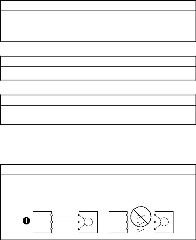
 Connect the servo amplifier power output (U, V, and W) to the servo motor power input (U, V, and W) directly. Do not let a magnetic contactor, etc. intervene. Otherwise, it may cause a malfunction.
Servo amplifier |
U |
Servo motor |
Servo amplifier |
U |
Servo motor |
U |
|
U |
|
||
|
|
|
|
||
V |
V |
M |
V |
V |
M |
|
|
||||
W |
W |
|
W |
W |
|
|
|
|
|
A - 2
(2) Usage
 CAUTION
 Before resetting an alarm, make sure that the run signal of the servo amplifier is off in order to prevent a sudden restart. Otherwise, it may cause an accident.
 Use the servo amplifier with the specified servo motor.
(3) Corrective actions
 CAUTION
 When it is assumed that a hazardous condition may occur due to a power failure or product malfunction, use a servo motor with an electromagnetic brake or external brake to prevent the condition.
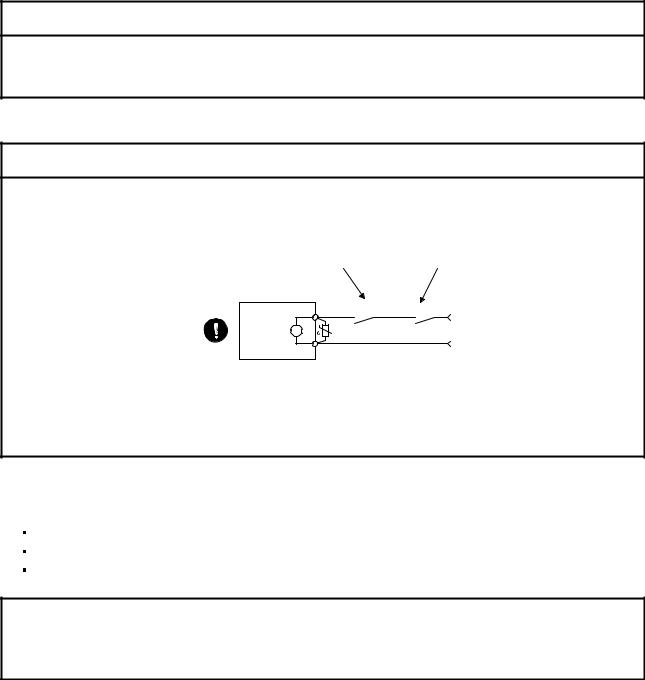
 Configure an electromagnetic brake circuit so that it is activated also by an external EMG stop switch.
Contacts must be opened when CALM (Common |
Contacts must be opened |
malfunction) or MBR (Electromagnetic brake |
with the EMG stop switch. |
interlock) turns off. |
|
Servo motor
|
RA |
B |
24 V DC |
Electromagnetic brake
 When any alarm has occurred, eliminate its cause, ensure safety, and deactivate the alarm before restarting operation.
 Provide an adequate protection to prevent unexpected restart after an instantaneous power failure.
<<About the manual>>
This Instruction Manual covers the following models.
MR-J4-_A
MR-J4-_B
MR-J4W_-_B
The symbols in the target column mean as follows.
MR-J4-_A: [A]
MR-J4-_B: [B]
MR-J4W_-_B: [WB]
A - 3

MEMO
A - 4
|
CONTENTS |
|
|
|
|
1. TROUBLESHOOTING |
1- 1 to 1-54 |
|
1.1 |
Alarm and warning list........................................................................................................................ |
1- 1 |
1.2 |
Remedies for alarms.......................................................................................................................... |
1- 5 |
1.3 |
Remedies for warnings ..................................................................................................................... |
1-44 |
|
|
|
APPENDIX |
App.- 1 to App.- 1 |
|
App. 1 Detection points of [AL. 25], [AL. 92], and [AL. 9F] ................................................................. |
App.- 1 |
|
1

MEMO
2

1. TROUBLESHOOTING
1. TROUBLESHOOTING
1.1 Alarm and warning list
When an error occurs during operation, the corresponding alarm or warning is displayed. If any alarm or warning has occurred, refer to section 1.2 and take the appropriate action. When an alarm occurs, ALM (Malfunction) will turn off.
Alarm
No. |
|
Name |
Detail |
Detail name |
|
|
display |
||||
|
|
|
|
|
|
10 |
Undervoltage |
|
10.1 |
Voltage drop in the control power |
|
|
|
|
|
10.2 |
Voltage drop in the main circuit power |
11 |
Switch setting error |
|
11.1 |
Axis number setting error |
|
|
|
|
|
11.2 |
Disabling control axis setting error |
12 |
Memory error 1 (RAM) |
12.1 |
RAM error 1 |
||
|
|
|
|
12.2 |
RAM error 2 |
|
|
|
|
12.3 |
RAM error 3 |
|
|
|
|
12.4 |
RAM error 4 |
|
|
|
|
12.5 |
RAM error 5 |
13 |
Clock error |
|
|
13.1 |
Clock error 1 |
|
|
|
|
13.2 |
Clock error 2 |
14 |
Control process error |
14.1 |
Control process error 1 |
||
|
|
|
|
14.2 |
Control process error 2 |
|
|
|
|
14.3 |
Control process error 3 |
|
|
|
|
14.4 |
Control process error 4 |
|
|
|
|
14.5 |
Control process error 5 |
|
|
|
|
14.6 |
Control process error 6 |
|
|
|
|
14.7 |
Control process error 7 |
|
|
|
|
14.8 |
Control process error 8 |
|
|
|
|
14.9 |
Control process error 9 |
|
|
|
|
14.A |
Control process error 10 |
15 |
Memory error 2 (EEP-ROM) |
15.1 |
EEP-ROM error at power on |
||
|
|
|
|
15.2 |
EEP-ROM error during operation |
16 |
Encoder |
initial |
communication |
16.1 |
Encoder initial communication - Receive data error 1 |
|
error 1 |
|
|
16.2 |
Encoder initial communication - Receive data error 2 |
|
|
|
|
16.3 |
Encoder initial communication - Receive data error 3 |
|
|
|
|
16.5 |
Encoder initial communication - Transmission data error 1 |
|
|
|
|
16.6 |
Encoder initial communication - Transmission data error 2 |
|
|
|
|
16.7 |
Encoder initial communication - Transmission data error 3 |
|
|
|
|
16.A |
Encoder initial communication - Process error 1 |
|
|
|
|
16.B |
Encoder initial communication - Process error 2 |
|
|
|
|
16.C |
Encoder initial communication - Process error 3 |
|
|
|
|
16.D |
Encoder initial communication - Process error 4 |
|
|
|
|
16.E |
Encoder initial communication - Process error 5 |
|
|
|
|
16.F |
Encoder initial communication - Process error 6 |
17 |
Board error |
|
|
17.1 |
Board error 1 |
|
|
|
|
17.3 |
Board error 2 |
|
|
|
|
17.4 |
Board error 3 |
|
|
|
|
17.5 |
Board error 4 |
|
|
|
|
17.6 |
Board error 5 |
19 |
Memory error 3 (Flash-ROM) |
19.1 |
Flash-ROM error 1 |
||
|
|
|
|
19.2 |
Flash-ROM error 2 |
1A |
Servo motor combination error |
1A.1 |
Servo motor combination error |
||
|
|
|
|
1A.2 |
Servo motor control mode combination error |
1E |
Encoder |
initial |
communication |
1E.1 |
Encoder malfunction |
|
error 2 |
|
|
|
|
1F |
Encoder |
initial |
communication |
1F.1 |
Incompatible encoder |
|
error 3 |
|
|
|
|
|
|
|
|
|
|
1 - 1

1. TROUBLESHOOTING
Alarm
No. |
|
|
Name |
Detail |
Detail name |
|
|
|
display |
||||
|
|
|
|
|
|
|
20 |
Encoder |
normal |
communication |
20.1 |
Encoder normal communication - Receive data error 1 |
|
|
error 1 |
|
|
|
20.2 |
Encoder normal communication - Receive data error 2 |
|
|
|
|
|
20.3 |
Encoder normal communication - Receive data error 3 |
|
|
|
|
|
20.5 |
Encoder normal communication - Transmission data error 1 |
|
|
|
|
|
20.6 |
Encoder normal communication - Transmission data error 2 |
|
|
|
|
|
20.7 |
Encoder normal communication - Transmission data error 3 |
|
|
|
|
|
20.9 |
Encoder normal communication - Receive data error 4 |
|
|
|
|
|
20.A |
Encoder normal communication - Receive data error 5 |
21 |
Encoder |
normal |
communication |
21.1 |
Encoder data error 1 |
|
|
error 2 |
|
|
|
21.2 |
Encoder data update error |
|
|
|
|
|
21.3 |
Encoder data waveform error |
|
|
|
|
|
21.4 |
Encoder non-signal error |
|
|
|
|
|
21.5 |
Encoder hardware error 1 |
|
|
|
|
|
21.6 |
Encoder hardware error 2 |
|
|
|
|
|
21.9 |
Encoder data error 2 |
24 |
Main circuit error |
|
24.1 |
Ground fault detected by hardware detection circuit |
||
|
|
|
|
|
24.2 |
Ground fault detected by software detection function |
25 |
Absolute position erased |
25.1 |
Servo motor encoder - Absolute position erased |
|||
27 |
Initial |
magnetic |
pole detection |
27.1 |
Magnetic pole detection - Abnormal termination |
|
|
error |
|
|
|
27.2 |
Magnetic pole detection - Time out error |
|
|
|
|
|
27.3 |
Magnetic pole detection - Limit switch error |
|
|
|
|
|
27.4 |
Magnetic pole detection - Estimated error |
|
|
|
|
|
27.5 |
Magnetic pole detection - Position deviation error |
|
|
|
|
|
27.6 |
Magnetic pole detection - Speed deviation error |
|
|
|
|
|
27.7 |
Magnetic pole detection - Current error |
28 |
Linear encoder error 2 |
28.1 |
Linear encoder - Environment error |
|||
2A |
Linear encoder error 1 |
2A.1 |
Linear encoder error 1-1 |
|||
|
|
|
|
|
2A.2 |
Linear encoder error 1-2 |
|
|
|
|
|
2A.3 |
Linear encoder error 1-3 |
|
|
|
|
|
2A.4 |
Linear encoder error 1-4 |
|
|
|
|
|
2A.5 |
Linear encoder error 1-5 |
|
|
|
|
|
2A.6 |
Linear encoder error 1-6 |
|
|
|
|
|
2A.7 |
Linear encoder error 1-7 |
|
|
|
|
|
2A.8 |
Linear encoder error 1-8 |
2B |
Encoder counter error |
2B.1 |
Encoder counter error 1 |
|||
|
|
|
|
|
2B.2 |
Encoder counter error 2 |
30 |
Regenerative error |
|
30.1 |
Regeneration heat error |
||
|
|
|
|
|
30.2 |
Regeneration signal error |
|
|
|
|
|
30.3 |
Regeneration feedback signal error |
31 |
Overspeed |
|
31.1 |
Abnormal motor speed |
||
32 |
Overcurrent |
|
32.1 |
Overcurrent detected at hardware detection circuit (during operation) |
||
|
|
|
|
|
32.2 |
Overcurrent detected at software detection function (during operation) |
|
|
|
|
|
32.3 |
Overcurrent detected at hardware detection circuit (during a stop) |
|
|
|
|
|
32.4 |
Overcurrent detected at software detection function (during a stop) |
33 |
Overvoltage |
|
33.1 |
Main circuit voltage error |
||
34 |
SSCNET receive error 1 |
34.1 |
SSCNET receive data error |
|||
|
|
|
|
|
34.2 |
SSCNET connector connection error |
|
|
|
|
|
34.3 |
SSCNET communication data error |
|
|
|
|
|
34.4 |
Hardware error signal detection |
35 |
Command frequency error |
35.1 |
Command frequency error |
|||
36 |
SSCNET receive error 2 |
36.1 |
Continuous communication data error |
|||
37 |
Parameter error |
|
37.1 |
Parameter setting range error |
||
|
|
|
|
|
37.2 |
Parameter combination error |
3A |
Inrush |
current suppression circuit |
3A.1 |
Inrush current suppression circuit error |
||
|
error |
|
|
|
|
|
3E |
Operation mode error |
3E.1 |
Operation mode error |
|||
|
|
|
|
|
|
|
1 - 2
1. TROUBLESHOOTING
Alarm
No. |
Name |
Detail |
Detail name |
|
display |
||||
|
|
|
||
42 |
Servo control error |
42.1 |
Servo control error by position deviation |
|
|
|
42.2 |
Servo control error by speed deviation |
|
|
|
42.3 |
Servo control error by torque/thrust deviation |
|
45 |
Main circuit device overheat |
45.1 |
Main circuit device overheat error |
|
46 |
Servo motor overheat |
46.1 |
Abnormal temperature of servo motor 1 |
|
|
|
46.2 |
Abnormal temperature of servo motor 2 |
|
|
|
46.3 |
Thermistor disconnected |
|
|
|
46.5 |
Abnormal temperature of servo motor 3 |
|
|
|
46.6 |
Abnormal temperature of servo motor 4 |
|
47 |
Cooling fan error |
47.1 |
Cooling fan stop error |
|
|
|
47.2 |
Cooling fan speed reduction error |
|
50 |
Overload 1 |
50.1 |
Thermal overload error 1 during operation |
|
|
|
50.2 |
Thermal overload error 2 during operation |
|
|
|
50.3 |
Thermal overload error 4 during operation |
|
|
|
50.4 |
Thermal overload error 1 during a stop |
|
|
|
50.5 |
Thermal overload error 2 during a stop |
|
|
|
50.6 |
Thermal overload error 4 during a stop |
|
51 |
Overload 2 |
51.1 |
Thermal overload error 3 during operation |
|
|
|
51.2 |
Thermal overload error 3 during a stop |
|
52 |
Error excessive |
52.1 |
Excess droop pulse 1 |
|
|
|
52.3 |
Excess droop pulse 2 |
|
|
|
52.4 |
Error excessive during 0 torque limit |
|
|
|
52.5 |
Excess droop pulse 3 |
|
54 |
Oscillation detection |
54.1 |
Oscillation detection error |
|
56 |
Forced stop error |
56.2 |
Over speed during forced stop |
|
|
|
56.3 |
Estimated distance over during forced stop |
|
63 |
STO timing error |
63.1 |
STO1 off |
|
|
|
63.2 |
STO2 off |
|
8A |
USB communication time-out error |
8A.1 |
USB communication time-out error |
|
8E |
USB communication error |
8E.1 |
USB communication receive error |
|
|
|
8E.2 |
USB communication checksum error |
|
|
|
8E.3 |
USB communication character error |
|
|
|
8E.4 |
USB communication command error |
|
|
|
8E.5 |
USB communication data number error |
|
888/ |
Watchdog |
88._/ |
Watchdog |
|
88888 |
|
8888._ |
|
|
|
|
|
|
1 - 3
1. TROUBLESHOOTING
Warning
No. |
|
Name |
|
Detail |
Detail name |
|
|
display |
|||
|
|
|
|
|
|
91 |
Servo amplifier overheat warning |
91.1 |
Main circuit device overheat warning |
||
92 |
Battery |
cable |
disconnection |
92.1 |
Encoder battery cable disconnection warning |
|
warning |
|
|
92.3 |
Battery degradation |
95 |
STO warning |
|
95.1 |
STO1 off detection |
|
|
|
|
|
95.2 |
STO2 off detection |
96 |
Home position setting warning |
96.1 |
In-position warning at home positioning |
||
|
|
|
|
96.2 |
Command input warning at home positioning |
|
|
|
|
96.3 |
Servo off warning at home positioning |
99 |
Stroke limit warning |
|
99.1 |
Forward rotation stroke end off |
|
|
|
|
|
99.2 |
Reverse rotation stroke end off |
9F |
Battery warning |
|
9F.1 |
Low battery |
|
|
|
|
|
9F.2 |
Battery degradation warning |
E0 |
Excessive regeneration warning |
E0.1 |
Excessive regeneration warning |
||
E1 |
Overload warning 1 |
|
E1.1 |
Thermal overload warning 1 during operation |
|
|
|
|
|
E1.2 |
Thermal overload warning 2 during operation |
|
|
|
|
E1.3 |
Thermal overload warning 3 during operation |
|
|
|
|
E1.4 |
Thermal overload warning 4 during operation |
|
|
|
|
E1.5 |
Thermal overload error 1 during a stop |
|
|
|
|
E1.6 |
Thermal overload error 2 during a stop |
|
|
|
|
E1.7 |
Thermal overload error 3 during a stop |
|
|
|
|
E1.8 |
Thermal overload error 4 during a stop |
E2 |
Servo motor overheat warning |
E2.1 |
Servo motor temperature warning |
||
E3 |
Absolute position counter warning |
E3.1 |
Multi-revolution counter travel distance excess warning |
||
|
|
|
|
E3.2 |
Encoder absolute positioning counter warning |
|
|
|
|
E3.5 |
Absolute position counter warning |
E4 |
Parameter warning |
|
E4.1 |
Parameter setting range error warning |
|
E5 |
ABS time-out warning |
E5.1 |
Time-out during ABS data transfer |
||
|
|
|
|
E5.2 |
ABSM off during ABS data transfer |
|
|
|
|
E5.3 |
SON off during ABS data transfer |
E6 |
Servo forced stop warning |
E6.1 |
Forced stop warning |
||
E7 |
Controller forced stop warning |
E7.1 |
Controller forced stop warning |
||
E8 |
Cooling |
fan speed reduction |
E8.1 |
Decreased cooling fan speed warning |
|
|
warning |
|
|
|
|
E9 |
Main circuit off warning |
E9.1 |
Servo-on signal on during main circuit off |
||
|
|
|
|
E9.2 |
Bus voltage drop during low speed operation |
|
|
|
|
E9.3 |
Ready-on signal on during main circuit off |
EA |
ABS servo-on warning |
EA.1 |
ABS servo-on warning |
||
EB |
The other axis error warning |
EB.1 |
The other axis error warning |
||
EC |
Overload warning 2 |
|
EC.1 |
Overload warning 2 |
|
ED |
Output watt excess warning |
ED.1 |
Output watt excess warning |
||
F0 |
Tough drive warning |
|
F0.1 |
Instantaneous power failure tough drive warning |
|
|
|
|
|
F0.3 |
Vibration tough drive warning |
F2 |
Drive recorder - Miswriting warning |
F2.1 |
Drive recorder - Area writing time-out warning |
||
|
|
|
|
F2.2 |
Drive recorder - Data miswriting warning |
F3 |
Oscillation detection warning |
F3.1 |
Oscillation detection warning |
||
|
|
|
|
|
|
1 - 4
1. TROUBLESHOOTING
1.2 Remedies for alarms
 When any alarm has occurred, eliminate its cause, ensure safety, and deactivate the alarm before restarting operation. Otherwise, it may cause injury.
CAUTION If [AL. 25 Absolute position erased] occurs, always make home position setting again. Otherwise, it may cause an unexpected operation.
 As soon as an alarm occurs, make the Servo-off status and interrupt the main circuit power.
POINT
 When any of the following alarms has occurred, do not cycle the power repeatedly to restart. Doing so will cause a malfunction of the servo amplifier and the servo motor. Remove its cause and allow about 30 minutes for cooling before resuming the operation.
[AL. 30 Regenerative error] • [AL. 45 Main circuit device overheat] [AL. 46 Servo motor overheat] • [AL. 50 Overload 1]
[AL. 51 Overload 2]
Remove the cause of the alarm in accordance with this section. Use MR Configurator2 to refer to a factor of alarm occurrence.
1 - 5

1. TROUBLESHOOTING
Alarm No.: 10 |
Name: Undervoltage |
|
|
|
|
||
Alarm content |
The voltage of the control circuit power supply has dropped. |
|
|
||||
The voltage of the main circuit power supply has dropped. |
|
|
|||||
|
|
|
|
||||
Displ |
Detail name |
|
Cause |
Check method |
Check result |
Action |
Targe |
ay |
|
t |
|||||
|
|
|
|
|
|
||
10.1 |
Voltage drop in |
(1) |
The connection of the |
Check the control |
It has a failure. |
Connect it correctly. |
[A] |
|
the control |
|
control circuit power |
circuit power supply |
|
|
[B] |
|
power |
|
supply connector |
connector. |
|
|
[WB] |
|
|
|
(CNP2) has a failure. |
|
It has no failure. |
Check (2). |
|
|
|
(2) |
The voltage of the |
Check if the voltage |
The voltage is lower |
Review the voltage of |
|
|
|
|
control circuit power |
of the control circuit |
than 160 V AC. |
the control circuit |
|
|
|
|
supply is low. |
power supply is lower |
|
power supply. |
|
|
|
|
|
than 160 V AC. |
The voltage is higher |
Check (3). |
|
|
|
|
|
|
than 160 V AC. |
|
|
|
|
(3) |
An instantaneous |
Check if the power |
It has a problem. |
Review the power. |
|
|
|
|
power failure has |
has a problem. |
|
|
|
|
|
|
occurred for longer |
|
|
|
|
|
|
|
time than the specified |
|
|
|
|
|
|
|
time. The time will be |
|
|
|
|
|
|
|
60 ms when [Pr. PA20] |
|
|
|
|
|
|
|
is "_ 0 _ _". The time |
|
|
|
|
|
|
|
will be the value set in |
|
|
|
|
|
|
|
[Pr. PF25] when [Pr. |
|
|
|
|
|
|
|
PA20] is "_ 1 _ _". |
|
|
|
|
10.2 |
Voltage drop in |
(1) |
The main circuit power |
Check the main |
It is disconnected. |
Connect it correctly. |
|
|
the main circuit |
|
supply connector |
circuit power supply |
|
|
|
|
power |
|
(CNP1) was |
connector. |
|
|
|
|
|
|
disconnected. |
|
|
|
|
|
|
|
|
|
It is connected. |
Check (2). |
|
|
|
(2) |
The voltage of the main |
Check if the voltage |
The voltage is lower |
Increase the voltage |
|
|
|
|
circuit power supply is |
of the main circuit |
than 160 V AC. |
of the main circuit |
|
|
|
|
low. |
power supply is lower |
|
power supply. |
|
|
|
|
|
than 160 V AC. |
The voltage is higher |
Check (3). |
|
|
|
|
|
|
than 160 V AC. |
|
|
|
|
(3) |
The alarm has |
Check that the bus |
The voltage is less |
Increase the |
|
|
|
|
occurred during |
voltage during |
than 200 V DC. |
acceleration time |
|
|
|
|
acceleration. |
acceleration is 200 V |
|
constant. Or increase |
|
|
|
|
|
DC or more. |
|
the power supply |
|
|
|
|
|
|
|
capacity. |
|
|
|
|
|
|
The voltage is 200 V |
Check (4). |
|
|
|
|
|
|
DC or more. |
|
|
|
|
(4) |
The servo amplifier is |
Check the bus |
The voltage of the |
Replace the servo |
|
|
|
|
malfunctioning. |
voltage value. |
main circuit power |
amplifier. |
|
|
|
|
|
|
supply is 160 V AC or |
|
|
|
|
|
|
|
more, and the bus |
|
|
|
|
|
|
|
voltage is less than |
|
|
|
|
|
|
|
200 V DC. |
|
|
1 - 6
1. TROUBLESHOOTING
Alarm No.: 11 |
Name: Switch setting error |
|
|
|
|
|
|||
Alarm content |
The setting of the axis selection rotary switch or auxiliary axis number setting switch is incorrect. |
|
|||||||
The setting of the disabling control axis switch is incorrect. |
|
|
|||||||
|
|
|
|
||||||
Displ |
Detail name |
|
Cause |
|
Check method |
|
Check result |
Action |
Targe |
ay |
|
|
|
t |
|||||
|
|
|
|
|
|
|
|
||
11.1 |
Axis number |
(1) |
The setting of the Axis |
|
Check the settings of |
When both of the |
Set the axis No. |
[WB] |
|
|
setting error |
|
No. is incorrect. |
|
the auxiliary axis |
auxiliary axis number |
correctly. |
|
|
|
|
|
|
|
number setting switch |
setting switches are |
|
|
|
|
|
|
|
|
(SW2) and axis |
on, check the axis |
|
|
|
|
|
|
|
|
selection rotary switch |
selection rotary switch |
|
|
|
|
|
|
|
|
(SW1). |
if "E" is selected for |
|
|
|
|
|
|
|
|
|
MR-J4W2, ("E" or "F" |
|
|
|
|
|
|
|
|
|
is selected for MR- |
|
|
|
|
|
|
|
|
|
J4W2). |
|
|
|
|
|
|
|
|
|
Both of the auxiliary |
Replace the servo |
|
|
|
|
|
|
|
|
axis number setting |
amplifier. |
|
|
|
|
|
|
|
|
switches are off. |
|
|
|
11.2 |
Disabling |
(1) |
The setting of the |
|
Check the setting of |
Check if the setting is |
Set it correctly. |
|
|
|
control axis |
|
disabling control axis |
|
the disabling control |
as follows. |
|
|
|
|
setting error |
|
switch is incorrect. |
|
axis switch. |
1) |
Only A-axis is |
|
|
|
|
|
|
|
|
|
disabled. |
|
|
|
|
|
|
|
|
2) |
Only B-axis is |
|
|
|
|
|
|
|
|
|
disabled. |
|
|
|
|
|
|
|
|
3) |
A-axis and B-axis |
|
|
|
|
|
|
|
|
|
are disabled. |
|
|
|
|
|
|
|
|
4) |
A-axis and C-axis |
|
|
|
|
|
|
|
|
|
are disabled. |
|
|
|
|
|
|
|
|
The setting is other |
Replace the servo |
|
|
|
|
|
|
|
|
than above. |
amplifier. |
|
|
|
|
|
|
|
|
|
|||
Alarm No.: 12 |
Name: Memory error 1 (RAM) |
|
|
|
|
|
|||
Alarm content |
A part (RAM) in the servo amplifier is failure. |
|
|
|
|
||||
Displ |
Detail name |
|
Cause |
|
Check method |
|
Check result |
Action |
Targe |
ay |
|
|
|
t |
|||||
|
|
|
|
|
|
|
|
||
12.1 |
RAM error 1 |
(1) |
A part in the servo |
|
Disconnect the cables |
It is repeatable. |
Replace the servo |
[A] |
|
|
|
|
amplifier is failure. |
|
except the control |
|
|
amplifier. |
[B] |
|
|
|
|
|
circuit power supply, |
It is not repeatable. |
Check (2). |
[WB] |
|
|
|
|
|
|
and then check the |
|
|
|
|
|
|
|
|
|
repeatability. |
|
|
|
|
|
|
(2) |
Something near the |
|
Check the power |
It has a failure. |
Take |
|
|
|
|
|
device caused it. |
|
supply for noise. |
|
|
countermeasures |
|
|
|
|
|
|
|
|
|
against its cause. |
|
12.2RAM error 2 Check it with the check method for [AL. 12.1].
12.3RAM error 3
12.4RAM error 4
12.5RAM error 5
1 - 7

1. TROUBLESHOOTING
Alarm No.: 13 |
Name: Clock error |
|
|
|
|
||
Alarm content |
A part in the servo amplifier is failure. |
|
|
|
|||
A clock error transmitted from the controller occurred. |
|
|
|||||
|
|
|
|
||||
Displ |
Detail name |
|
Cause |
Check method |
Check result |
Action |
Targe |
ay |
|
t |
|||||
|
|
|
|
|
|
||
13.1 |
Clock error 1 |
(1) |
A part in the servo |
Disconnect the cables |
It is repeatable. |
Replace the servo |
[A] |
|
|
|
amplifier is failure. |
except the control |
|
amplifier. |
[B] |
|
|
|
|
circuit power supply, |
It is not repeatable. |
Check (2). |
[WB] |
|
|
|
|
and then check the |
|
|
|
|
|
|
|
repeatability. |
|
|
|
|
|
(2) |
A clock error |
Check if the error |
It occurs. |
Replace the |
[B] |
|
|
|
transmitted from the |
occurs when you |
|
controller. |
[WB] |
|
|
|
controller occurred. |
connect the amplifier |
It does not occur. |
Check (3). |
|
|
|
|
|
to the controller. |
|
|
|
|
|
(3) |
The servo amplifier of |
Check if the servo |
It is malfunctioning. |
Replace the servo |
|
|
|
|
the next axis is |
amplifier of the next |
|
amplifier of the next |
|
|
|
|
malfunctioning. |
axis is malfunctioning. |
|
axis. |
|
|
|
|
|
|
It is not |
Check (4). |
|
|
|
|
|
|
malfunctioning. |
|
|
|
|
(4) |
Something near the |
Check the power |
It has a failure. |
Take |
[A] |
|
|
|
device caused it. |
supply for noise. |
|
countermeasures |
[B] |
|
|
|
|
Check if the |
|
against its cause. |
[WB] |
|
|
|
|
connector is shorted. |
|
|
|
13.2 |
Clock error 2 |
Check it with the check method for [AL. 13.1]. |
|
|
|
||
1 - 8

1. TROUBLESHOOTING
Alarm No.: 14 |
Name: Control process error |
|
|
|
|
||
Alarm content |
The process did not complete within the specified time. |
|
|
||||
Displ |
Detail name |
|
Cause |
Check method |
Check result |
Action |
Targe |
ay |
|
t |
|||||
|
|
|
|
|
|
||
14.1 |
Control |
(1) |
The parameter setting |
Check if the |
It is incorrect. |
Set it correctly. |
[A] |
|
process error 1 |
|
is incorrect. |
parameter setting is |
|
|
[B] |
|
|
|
|
incorrect. |
|
|
[WB] |
|
|
|
|
|
It is correct. |
Check (2). |
|
|
|
(2) |
Something near the |
Check the power |
It has a failure. |
Take |
|
|
|
|
device caused it. |
supply for noise. |
|
countermeasures |
|
|
|
|
|
Check if the |
|
against its cause. |
|
|
|
|
|
connector is shorted. |
It has no failure. |
Check (3). |
|
|
|
|
|
|
|
|
|
|
|
(3) |
The servo amplifier is |
Replace the servo |
It is not repeatable. |
Replace the servo |
|
|
|
|
malfunctioning. |
amplifier, and then |
|
amplifier. |
|
|
|
|
|
check the |
|
|
|
|
|
|
|
repeatability. |
|
|
|
14.2 |
Control |
(1) |
A synchronous signal |
Replace the |
It is repeatable. |
Replace the servo |
[B] |
|
process error 2 |
|
error transmitted from |
controller, and then |
|
amplifier. |
[WB] |
|
|
|
the controller occurred. |
check the |
It is not repeatable. |
Check (2). |
|
|
|
|
|
repeatability. |
|
|
|
|
|
(2) |
The parameter setting |
Check if the |
It is incorrect. |
Set it correctly. |
[A] |
|
|
|
is incorrect. |
parameter setting is |
|
|
[B] |
|
|
|
|
incorrect. |
|
|
[WB] |
|
|
|
|
|
It is correct. |
Check (3). |
|
|
|
(3) |
Something near the |
Check the power |
It has a failure. |
Take |
|
|
|
|
device caused it. |
supply for noise. |
|
countermeasures |
|
|
|
|
|
Check if the |
|
against its cause. |
|
|
|
|
|
connector is shorted. |
It has no failure. |
Check (4). |
|
|
|
(4) |
The servo amplifier is |
Replace the servo |
It is not repeatable. |
Replace the servo |
|
|
|
|
malfunctioning. |
amplifier, and then |
|
amplifier. |
|
|
|
|
|
check the |
|
|
|
|
|
|
|
repeatability. |
|
|
|
14.3 |
Control |
Check it with the check method for [AL. 14.1]. |
|
|
|
||
|
process error 3 |
|
|
|
|
|
|
14.4 |
Control |
|
|
|
|
|
|
|
process error 4 |
|
|
|
|
|
|
14.5 |
Control |
|
|
|
|
|
|
|
process error 5 |
|
|
|
|
|
|
14.6 |
Control |
|
|
|
|
|
|
|
process error 6 |
|
|
|
|
|
|
14.7 |
Control |
|
|
|
|
|
|
|
process error 7 |
|
|
|
|
|
|
14.8 |
Control |
|
|
|
|
|
|
|
process error 8 |
|
|
|
|
|
|
14.9 |
Control |
|
|
|
|
|
|
|
process error 9 |
|
|
|
|
|
|
14.A |
Control process |
|
|
|
|
|
|
|
error 10 |
|
|
|
|
|
|
1 - 9

1. TROUBLESHOOTING
Alarm No.: 15 |
Name: Memory error 2 (EEP-ROM) |
|
|
|
|||
Alarm content |
A part (EEP-ROM) in the servo amplifier is failure. |
|
|
|
|||
Displ |
Detail name |
|
Cause |
Check method |
Check result |
Action |
Targe |
ay |
|
t |
|||||
|
|
|
|
|
|
||
15.1 |
EEP-ROM error |
(1) |
EEP-ROM is |
Disconnect the cables |
It is repeatable. |
Replace the servo |
[A] |
|
at power on |
|
malfunctioning at power |
except the control |
|
amplifier. |
[B] |
|
|
|
on. |
circuit power supply, |
It is not repeatable. |
Check (2). |
[WB] |
|
|
|
|
and then check the |
|
|
|
|
|
|
|
repeatability. |
|
|
|
|
|
(2) |
Something near the |
Check the power |
It has a failure. |
Take |
|
|
|
|
device caused it. |
supply for noise. |
|
countermeasures |
|
|
|
|
|
Check if the connector |
|
against its cause. |
|
|
|
|
|
is shorted. |
It has no failure. |
Check (3). |
|
|
|
(3) |
The number of write |
Check if parameters |
It has a failure. |
Replace the servo |
|
|
|
|
times exceeded |
has been used very |
|
amplifier. Change the |
|
|
|
|
100,000. |
frequently. |
|
process to use |
|
|
|
|
|
|
|
parameters less |
|
|
|
|
|
|
|
frequently after |
|
|
|
|
|
|
|
replacement. |
|
15.2 |
EEP-ROM error |
(1) |
EEP-ROM is |
Check if the error |
It occurs. |
Replace the servo |
|
|
during operation |
|
malfunctioning during |
occurs when you |
|
amplifier. |
|
|
|
|
normal operation. |
change parameters |
It does not occur. |
Check (2). |
|
|
|
|
|
during normal |
|
|
|
|
|
|
|
operation. |
|
|
|
|
|
(2) |
A write error occurred |
Check if the alarm |
It takes an hour or |
Replace the servo |
|
|
|
|
while tuning results was |
occurs after an hour |
more. |
amplifier. |
|
|
|
|
processed. |
from power on. |
It takes less than an |
Check (3). |
|
|
|
|
|
|
hour. |
|
|
|
|
(3) |
Something near the |
Check the power |
It has a failure. |
Take |
|
|
|
|
device caused it. |
supply for noise. |
|
countermeasures |
|
|
|
|
|
Check if the connector |
|
against its cause. |
|
|
|
|
|
is shorted. |
|
|
|
|
|
|
|
|
|||
Alarm No.: 16 |
Name: Encoder initial communication error 1 |
|
|
|
|||
Alarm content |
Communication error occurred between encoder and servo amplifier. |
|
|
||||
Displ |
Detail name |
|
Cause |
Check method |
Check result |
Action |
Targe |
ay |
|
t |
|||||
|
|
|
|
|
|
||
16.1 |
Encoder initial |
(1) |
An encoder cable is |
Check if the encoder |
It has a failure. |
Replace or repair the |
[A] |
|
communication |
|
malfunctioning. |
cable is disconnected |
|
cable. |
[B] |
|
- Receive data |
|
|
or shorted. |
|
|
[WB] |
|
error 1 |
|
|
|
|
|
|
|
|
|
|
|
It has no failure. |
Check (2). |
|
|
|
(2) |
The servo amplifier is |
Replace the servo |
It is not repeatable. |
Replace the servo |
|
|
|
|
malfunctioning. |
amplifier, and then |
|
amplifier. |
|
|
|
|
|
check the |
It is repeatable. |
Check (3). |
|
|
|
|
|
repeatability. |
|
|
|
|
|
(3) |
An encoder is |
Replace the servo |
It is not repeatable. |
Replace the servo |
|
|
|
|
malfunctioning. |
motor or linear |
|
motor. |
|
|
|
|
|
encoder, and then |
It is repeatable. |
Check (4). |
|
|
|
|
|
check the |
|
|
|
|
|
|
|
repeatability. |
|
|
|
|
|
(4) |
Something near the |
Check the noise, |
It has a failure. |
Take |
|
|
|
|
device caused it. |
ambient temperature, |
|
countermeasures |
|
|
|
|
|
vibration, etc. |
|
against its cause. |
|
16.2 |
Encoder initial |
Check it with the check method for [AL. 16.1]. |
|
|
|
||
|
communication |
|
|
|
|
|
|
|
- Receive data |
|
|
|
|
|
|
|
error 2 |
|
|
|
|
|
|
1 - 10

1. TROUBLESHOOTING
Alarm No.: 16 |
Name: Encoder initial communication error 1 |
|
|
|
|||
Alarm content |
Communication error occurred between encoder and servo amplifier. |
|
|
||||
Displ |
Detail name |
|
Cause |
Check method |
Check result |
Action |
Targe |
ay |
|
t |
|||||
|
|
|
|
|
|
||
16.3 |
Encoder initial |
(1) |
An axis not used is not |
Check the setting of |
It is not set as |
Set it as disabled- |
[WB] |
|
communication - |
|
set as disabled-axis. |
the disabling control |
disabled-axis. |
axis. |
|
|
Receive data |
|
|
axis switch (SW2). |
|
|
|
|
error 3 |
|
|
|
It is set as disabled- |
Check (2). |
|
|
|
|
|
|
axis. |
|
|
|
|
(2) |
An encoder cable was |
Check if the encoder |
It is not connected. |
Connect it correctly. |
[A] |
|
|
|
disconnected. |
cable is connected |
|
|
[B] |
|
|
|
|
correctly. |
It is connected. |
Check (3). |
[WB] |
|
|
(3) |
The parameter setting |
Check the parameter |
The setting is |
Set it correctly. |
|
|
|
|
of two-wire type/four- |
setting. |
incorrect. |
|
|
|
|
|
wire type is incorrect. |
|
|
|
|
|
|
|
|
The setting is correct. |
Check (4). |
|
|
|
|
|
Type A: [Pr. PC22] |
|
|
||
|
|
|
|
|
|
|
|
|
|
|
Type B: [Pr. PC04] |
|
|
|
|
|
|
|
|
|
|
|
|
|
|
(4) |
An encoder cable is |
Check if the encoder |
It has a failure. |
Replace or repair the |
|
|
|
|
malfunctioning. |
cable is disconnected |
|
cable. |
|
|
|
|
|
or shorted. |
It has no failure. |
Check (5). |
|
|
|
(5) |
The voltage of the |
Check the voltage of |
The control circuit |
Review the power |
|
|
|
|
control circuit power |
the control circuit |
power supply has |
and related parts. |
|
|
|
|
supply has been |
power supply. |
been an |
|
|
|
|
|
unstable. |
|
instantaneous power |
|
|
|
|
|
|
|
failure. |
|
|
|
|
|
|
|
It has no failure. |
Check (6). |
|
|
|
(6) |
The servo amplifier is |
Replace the servo |
It is not repeatable. |
Replace the servo |
|
|
|
|
malfunctioning. |
amplifier, and then |
|
amplifier. |
|
|
|
|
|
check the |
It is repeatable. |
Check (7). |
|
|
|
|
|
repeatability. |
|
|
|
|
|
(7) |
An encoder is |
Replace the servo |
It is not repeatable. |
Replace the servo |
|
|
|
|
malfunctioning. |
motor, and then |
|
motor. |
|
|
|
|
|
check the |
It is repeatable. |
Check (8). |
|
|
|
|
|
repeatability. |
|
|
|
|
|
(8) |
Something near the |
Check the noise, |
It has a failure. |
Take |
|
|
|
|
device caused it. |
ambient temperature, |
|
countermeasures |
|
|
|
|
|
vibration, etc. |
|
against its cause. |
|
16.5 |
Encoder initial |
Check it with the check method for [AL. 16.1]. |
|
|
|
||
|
communication - |
|
|
|
|
|
|
|
Transmission |
|
|
|
|
|
|
|
data error 1 |
|
|
|
|
|
|
16.6 |
Encoder initial |
|
|
|
|
|
|
|
communication - |
|
|
|
|
|
|
|
Transmission |
|
|
|
|
|
|
|
data error 2 |
|
|
|
|
|
|
16.7 |
Encoder initial |
|
|
|
|
|
|
|
communication - |
|
|
|
|
|
|
|
Transmission |
|
|
|
|
|
|
|
data error 3 |
|
|
|
|
|
|
1 - 11

1. TROUBLESHOOTING
Alarm No.: 16 |
Name: Encoder initial communication error 1 |
|
|
|
|||
Alarm content |
Communication error occurred between encoder and servo amplifier. |
|
|
||||
Displ |
Detail name |
|
Cause |
Check method |
Check result |
Action |
Targe |
ay |
|
t |
|||||
|
|
|
|
|
|
||
16.A |
Encoder initial |
(1) |
The servo amplifier is |
Replace the servo |
It is not repeatable. |
Replace the servo |
[A] |
|
communication - |
|
malfunctioning. |
amplifier, and then |
|
amplifier. |
[B] |
|
Process error 1 |
|
|
check the |
|
|
[WB] |
|
|
|
|
repeatability. |
It is repeatable. |
Check (2). |
|
|
|
(2) |
An encoder is |
Replace the servo |
It is not repeatable. |
Replace the servo |
|
|
|
|
malfunctioning. |
motor, and then check |
|
motor. |
|
|
|
|
|
the repeatability. |
It is repeatable. |
Check (3). |
|
|
|
(3) |
Something near the |
Check the noise, |
It has a failure. |
Take |
|
|
|
|
device caused it. |
ambient temperature, |
|
countermeasures |
|
|
|
|
|
vibration, etc. |
|
against its cause. |
|
16.B |
Encoder initial |
Check it with the check method for [AL. 16.A]. |
|
|
|
||
|
communication - |
|
|
|
|
|
|
|
Process error 2 |
|
|
|
|
|
|
16.C |
Encoder initial |
|
|
|
|
|
|
|
communication - |
|
|
|
|
|
|
|
Process error 3 |
|
|
|
|
|
|
16.D |
Encoder initial |
|
|
|
|
|
|
|
communication - |
|
|
|
|
|
|
|
Process error 4 |
|
|
|
|
|
|
16.E |
Encoder initial |
|
|
|
|
|
|
|
communication - |
|
|
|
|
|
|
|
Process error 5 |
|
|
|
|
|
|
16.F |
Encoder initial |
|
|
|
|
|
|
|
communication - |
|
|
|
|
|
|
|
Process error 6 |
|
|
|
|
|
|
1 - 12

1. TROUBLESHOOTING
Alarm No.: 17 |
Name: Board error |
|
|
|
|
||
Alarm content |
A part in the servo amplifier is malfunctioning. |
|
|
|
|||
Displ |
Detail name |
|
Cause |
Check method |
Check result |
Action |
Targe |
ay |
|
t |
|||||
|
|
|
|
|
|
||
17.1 |
Board error 1 |
(1) |
A current detection |
Check if the alarm |
It occurs. |
Replace the servo |
[A] |
|
|
|
circuit is |
occurs during the |
|
amplifier. |
[B] |
|
|
|
malfunctioning. |
servo-on status. |
|
|
[WB] |
|
|
|
|
|
It does not occur. |
Check (2). |
|
|
|
(2) |
Something near the |
Check the noise, |
It has a failure. |
Take |
|
|
|
|
device caused it. |
ambient temperature, |
|
countermeasures |
|
|
|
|
|
etc. |
|
against its cause. |
|
17.3 |
Board error 2 |
Check it with the check method for [AL. 17.1]". |
|
|
|
||
17.4 |
Board error 3 |
(1) |
The servo amplifier |
Disconnect the cables |
It is repeatable. |
Replace the servo |
|
|
|
|
recognition signal was |
except the control |
|
amplifier. |
|
|
|
|
not read properly. |
circuit power supply, |
It is not repeatable. |
Check (2). |
|
|
|
|
|
and then check the |
|
|
|
|
|
|
|
repeatability. |
|
|
|
|
|
(2) |
Something near the |
Check the noise, |
It has a failure. |
Take |
|
|
|
|
device caused it. |
ambient temperature, |
|
countermeasures |
|
|
|
|
|
etc. |
|
against its cause. |
|
17.5 |
Board error 4 |
(1) |
The setting value of the |
Disconnect the cables |
It is repeatable. |
Replace the servo |
[B] |
|
|
|
rotary switch (SW1) |
except the control |
|
amplifier. |
[WB] |
|
|
|
was not read properly. |
circuit power supply, |
It is not repeatable. |
Check (2). |
|
|
|
|
|
and then check the |
|
||
|
|
|
|
|
|
|
|
|
|
|
|
repeatability. |
|
|
|
|
|
(2) |
Something near the |
Check the noise, |
It has a failure. |
Take |
|
|
|
|
device caused it. |
ambient temperature, |
|
countermeasures |
|
|
|
|
|
etc. |
|
against its cause. |
|
17.6 |
Board error 5 |
(1) |
The setting value of the |
Disconnect the cables |
It is repeatable. |
Replace the servo |
|
|
|
|
DIP switches (SW2) |
except the control |
|
amplifier. |
|
|
|
|
was not read properly. |
circuit power supply, |
It is not repeatable. |
Check (2). |
|
|
|
|
|
and then check the |
|
|
|
|
|
|
|
repeatability. |
|
|
|
|
|
(2) |
Something near the |
Check the noise, |
It has a failure. |
Take |
|
|
|
|
device caused it. |
ambient temperature, |
|
countermeasures |
|
|
|
|
|
etc. |
|
against its cause. |
|
1 - 13
Loading...