


 Loading...
MELDAS is a registered trademark of Mitsubishi Electric Corporation.
Other company and product names that appear in this manual are trademarks or registered trademarks of their respective companies.
Introduction
Thank you for selecting the Mitsubishi numerical control unit.
This instruction manual describes the handling and caution points for using this AC servo/spindle.
Incorrect handling may lead to unforeseen accidents, so always read this instruction manual thoroughly to ensure correct usage.
Make sure that this instruction manual is delivered to the end user. Always store this manual in a safe place.
All specifications for the MDS-CH Series are described in this manual. However, each CNC may not be provided with all specifications, so refer to the specifications for the
CNC on hand before starting use.
Notes on Reading This Manual
(1)Since the description of this specification manual deals with NC in general, for the specifications of individual machine tools, refer to the manuals issued by the respective machine manufacturers. The "restrictions" and "available functions" described in the manuals issued by the machine manufacturers have precedence to those in this manual.
(2)This manual describes as many special operations as possible, but it should be kept in mind that items not mentioned in this manual cannot be performed.

Precautions for safety
Please read this manual and auxiliary documents before starting installation, operation, maintenance or inspection to ensure correct usage. Thoroughly understand the device, safety information and precautions before starting operation.
The safety precautions in this instruction manual are ranked as "WARNING" and "CAUTION".
DANGER

 WARNING
CAUTION
When there is a potential risk of fatal or serious injuries if handling is mistaken.
When a dangerous situation, or fatal or serious injuries may occur if handling is mistaken.
When a dangerous situation may occur if handling is mistaken leading to medium or minor injuries, or physical damage.
Note that some items described as |
|
|
CAUTION |
may lead to major results depending on |
|
|
|||
|
|
|
|
|
the situation. In any case, important information that must be observed is described.
The numeric control unit is configured of the control unit, operation board, servo drive unit, spindle drive unit, power supply, servomotor and spindle motor, etc.
In this manual, the following items are generically called the "motor".
•Servomotor
•Linear servomotor
•Spindle motor
In this manual, the following items are generically called the "unit".
•Servo drive unit
•Spindle drive unit
•Power supply unit
•Scale I/F unit
•Magnetic pole detection unit

 DANGER
There are no "DANGER" items in this manual.
 WARNING
1. Electric shock prevention
Do not open the front cover while the power is ON or during operation. Failure to observe this could lead to electric shocks.
Do not operate the unit with the front cover removed. The high voltage terminals and charged sections will be exposed, and can cause electric shocks.
Do not remove the front cover even when the power is OFF unless carrying out wiring work or periodic inspections. The inside of the units is charged, and can cause electric shocks.
Wait at least 15 minutes after turning the power OFF before starting wiring or inspections. Failure to observe this could lead to electric shocks.
Ground the unit and motor with Class C (former class 3) grounding or higher.
Wiring and inspection work must be done by a qualified technician.
Wire the servo drive unit and servomotor after installation. Failure to observe this could lead to electric shocks.
Do not touch the switches with wet hands. Failure to observe this could lead to electric shocks.
Do not damage, apply forcible stress, place heavy items on the cables or get them caught. Failure to observe this could lead to electric shocks.
2. Injury prevention
The linear servomotor uses a powerful magnet on the secondary side, and could adversely affect pacemakers, etc.
During installation and operation of the machine, do not place portable items that could malfunction or fail due to the influence of the linear servomotor's magnetic force.
Take special care not to pinch fingers, etc., when installing (and unpacking) the linear servomotor.
CAUTION
1. Fire prevention
Install the units, motors and regenerative resistor on noncombustible material. Direct installation on combustible material or near combustible materials could lead to fires.
Shut off the power on the power supply unit side if a fault occurs in the units. Fires could be caused if a large current continues to flow.
Provide a sequence that shut off the power at the regenerative resistor error signal-ON when using the regenerative resistor. The regenerative resistor could abnormally overheat and cause a fire due to a fault in the regenerative transistor, etc.
The battery unit could heat up, ignite or rupture if submerged in water, or if the poles are incorrectly wired.

CAUTION
2. Injury prevention
Do not apply a voltage other than that specified in Instruction Manual on each terminal. Failure to observe this item could lead to ruptures or damage, etc.
Do not mistake the terminal connections. Failure to observe this item could lead to ruptures or damage, etc.
Do not mistake the polarity ( + , – ). Failure to observe this item could lead to ruptures or damage, etc.
Do not touch the radiation fin on unit back face, regenerative resistor or motor, etc., or place parts (cables, etc.) while the power is turned ON or immediately after turning the power OFF. These parts may reach high temperatures, and can cause burns.
Structure the cooling fan on the unit back face so that it cannot be touched after installation. Touching the cooling fan during operation could lead to injuries.
3. Various precautions
Observe the following precautions. Incorrect handling of the unit could lead to faults, injuries and electric shocks, etc.
(1) Transportation and installation
Correctly transport the product according to its weight.
Use the motor's hanging bolts only when transporting the motor. Do not transport the motor when it is installed on the machine.
Do not stack the products above the tolerable number.
Do not hold the cables, axis or detector when transporting the motor.
Do not hold the connected wires or cables when transporting the units.
Do not hold the front cover when transporting the unit. The unit could drop.
Follow this Instruction Manual and install the unit or motor in a place where the weight can be borne.
Do not get on top of or place heavy objects on the unit.
Always observe the installation directions of the units or motors.
Secure the specified distance between the units and control panel, or between the servo drive unit and other devices.
Do not install or run a unit or motor that is damaged or missing parts.
Do not block the intake or exhaust ports of the motor provided with a cooling fan.
Do not let foreign objects enter the units or motors. In particular, if conductive objects such as screws or metal chips, etc., or combustible materials such as oil enter, rupture or breakage could occur.
The units and motors are precision devices, so do not drop them or apply strong impacts to them.

CAUTION
 Store and use the units under the following environment conditions.
Environment |
Conditions |
|||
|
|
|||
Unit |
Motor |
|||
|
|
|||
|
|
|
|
|
|
During operation |
0°C to 55°C |
0°C to 40°C |
|
Ambient |
(with no freezing) |
(with no freezing) |
||
|
||||
temperature |
|
|
|
|
During storage/ |
–15°C to 70°C |
–20°C to 65°C Note 1) |
||
|
transportation |
(with no freezing) |
(with no freezing) |
|
|
During operation |
90%RH or less |
20% to 90%RH |
|
Ambient |
(with no dew condensation) |
(with no dew condensation) |
||
|
||||
humidity |
During storage/ |
90%RH or less |
90% RH or less |
|
|
transportation |
(with no dew condensation) |
(with no dew condensation) |
|
|
|
Indoors (where unit is not |
subject to direct sunlight), |
|
Atmosphere |
|
with no corrosive gas, combustible gas, oil mist, |
||
|
|
dust or conductive particles |
||
|
|
Operation/storage: 1,000m or less above sea level |
||
Altitude |
|
Transportation: 10,000m or less above sea level |
||
|
(This specified value may be exceeded |
|||
|
|
|||
|
|
only during air-transport) |
||
|
|
|
||
Vibration |
|
To follow each unit and motor specifications |
||
|
|
|
|
|
Note 1) -15°C to 55°C for linear servomotor.
Securely fix the servomotor to the machine. Insufficient fixing could lead to the servomotor slipping off during operation.
Always install the servomotor with reduction gear in the designated direction. Failure to do so could lead to oil leaks.
Structure the rotary sections of the motor so that it can never be touched during operation. Install a cover, etc., on the shaft.
When installing a coupling to a servomotor shaft end, do not apply an impact by hammering, etc. The detector could be damaged.
Do not apply a load exceeding the tolerable load onto the servomotor shaft. The shaft could break.
Store the motor in the package box.
When inserting the shaft into the built-in IPM motor, do not heat the rotor higher than 130°C. The magnet could be demagnetized, and the specifications characteristics will not be ensured.
Always use a nonmagnetic tool (explosion-proof beryllium copper alloy safety tool: NGK Insulators) when installing the linear servomotor.
Always provide a mechanical stopper on the end of the linear servomotor's travel path.
If the unit has been stored for a long time, always check the operation before starting actual operation. Please contact the Service Center or Service Station.

CAUTION
(2) Wiring
Correctly and securely perform the wiring. Failure to do so could lead to runaway of the motor.
Do not install a condensing capacitor, surge absorber or radio noise filter on the output side of the drive unit.
Correctly connect the output side of the drive unit (terminals U, V, W). Failure to do so could lead to abnormal operation of the motor.
Always install an AC reactor for each power supply unit.
Always install an appropriate breaker for each power supply unit. Breakers cannot be shared by several units.
Direct application of a commercial power supply to the motor could cause burning. Always connect the motor to the drive unit's output terminals (U, V, W).
When using an inductive load such as a relay, always connect a diode as a noise measure parallel to the load.
When using a capacitance load such as a lamp, always connect a protective resistor as a noise measure serial to the load.
Do not reverse the direction of a diode which |
Drive unit |
Diode reverse orientation |
|||||
connect to a DC relay for the control output |
|
|
|
|
|
|
|
signals to suppress a surge. Connecting it |
COM |
|
|
|
|
|
|
|
|
|
|
|
|
||
backwards could cause the drive unit to |
(24VDC) |
|
|
|
|
|
|
|
|
|
|
|
|
|
|
|
|
|
|
|
|
|
|
malfunction so that signals are not output, and |
|
|
|
|
|
|
|
emergency stop and other safety circuits are |
Control output |
|
|
|
|
|
|
inoperable. |
signal |
|
|
|
RA |
|
|
|
|
|
|
||||
|
|
|
|
|
|
|
|
Do not connect/disconnect the cables connected between the units while the power is ON.
Securely tighten the cable connector fixing screw or fixing mechanism. An insecure fixing could cause the cable to fall off while the power is ON.
When using a shielded cable instructed in the connection manual, always ground the cable with a cable clamp, etc.
Always separate the signals wires from the drive wire and power line.
Use wires and cables that have a wire diameter, heat resistance and flexibility that conforms to the system.

CAUTION
(3) Trial operation and adjustment
Check and adjust each program and parameter before starting operation. Failure to do so could lead to unforeseen operation of the machine.
Do not make remarkable adjustments and changes as the operation could become unstable.
The usable motor and unit combination is predetermined. Always check the models before starting trial operation.
If the axis is unbalanced due to gravity, etc., balance the axis using a counterbalance, etc.
The linear servomotor does not have a stopping device such as magnetic brakes. Install a stopping device on the machine side.
(4) Usage methods
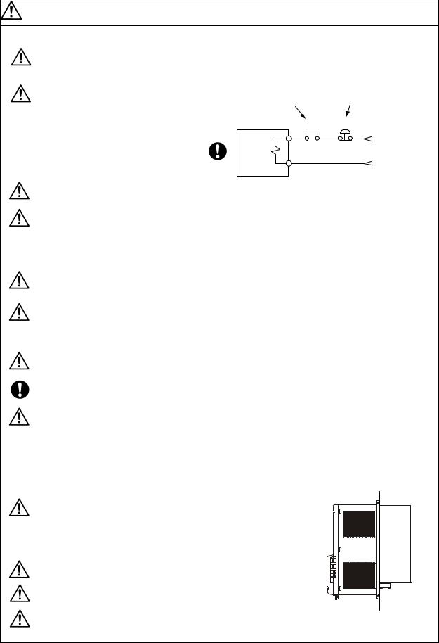
Install an external emergency stop circuit so that the operation can be stopped and power shut off immediately.
Turn the power OFF immediately if smoke, abnormal noise or odors are generated from the unit or motor.
Unqualified persons must not disassemble or repair the unit. Never make modifications.
Reduce magnetic damage by installing a noise filter. The electronic devices used near the unit could be affected by magnetic noise.
Use the unit, motor and regenerative resistor with the designated combination. Failure to do so could lead to fires or trouble.
The brake (magnetic brake) assembled into the servomotor are for holding, and must not be used for normal braking. Do not apply the brakes in the servo ON state. Doing so will lead to a drop in the brake life. Always turn the servo OFF before applying the brakes.
There may be cases when holding is not possible due to the magnetic brake's life or the machine construction (when ball screw and servomotor are coupled via a timing belt, etc.). Install a stop device to ensure safety on the machine side.
After changing the programs/parameters or after maintenance and inspection, always test the operation before starting actual operation.
Do not enter the movable range of the machine during automatic operation. Never place body parts near or touch the spindle during rotation.
Follow the power supply specification conditions given in the separate specifications manual for the power (input voltage, input frequency, tolerable sudden power failure time, etc.).
CAUTION
(5) Troubleshooting
If a hazardous situation is predicted during power failure or product trouble, use a servomotor with magnetic brakes or install an external brake mechanism.
Use a double circuit configuration that allows the operation circuit for the magnetic brakes to be operated even by the external emergency stop signal.
Shut off with the servomotor brake control output.
Servomotor MBR
Magnetic brake
Shut off with NC brake control PLC output.
EMG
24VDC
Always turn the input power OFF when an alarm occurs.
Never go near the machine after restoring the power after a power failure, as the machine could start suddenly. (Design the machine so that personal safety can be ensured even if the machine starts suddenly.)
(6) Maintenance, inspection and part replacement
Always backup the programs and parameters in the CNC device before starting maintenance or inspections.
The capacity of the electrolytic capacitor will drop over time due to self-discharging, etc. To prevent secondary disasters due to failures, replacing this part every five years when used under a normal environment is recommended. Contact the Service Center or Service Station for replacement.
Do not perform a megger test (insulation resistance measurement) during inspections.
If the battery low warning is issued, back up the machining programs, tool data and parameters with an input/output unit, and then replace the battery.
Do not short circuit, charge, overheat, incinerate or disassemble the battery.
The heat radiating fin used in the 37kW and smaller unit contains substitute Freon as the refrigerant.
Take care not to damage the heat radiating fin during maintenance and replacement work.
(7) Disposal
Do not dispose of this unit as general industrial waste. The 37kW and smaller unit with heat radiating fin protruding from the back of the unit contains substitute Freon. Do not dispose of this type of unit as general industrial waste. Always return to the Service Center or Service Station.
Do not disassemble the unit or motor.
Dispose of the battery according to local laws.
Heat radiating fin
Always return the secondary side (magnet side) of the linear servomotor to the Service Center or Service Station.
CAUTION
(8) Transportation
The unit and motor are precision parts and must be handled carefully.
According to a United Nations Advisory, the battery unit and battery must be transported according to the rules set forth by the International Civil Aviation Organization (ICAO), International Air Transportation Association (IATA), International Maritime Organization (IMO), and United States Department of Transportation (DOT), etc.
(9) General precautions
The drawings given in this Specifications and Maintenance Instruction Manual show the covers and safety partitions, etc., removed to provide a clearer explanation. Always return the covers or partitions to their respective places before starting operation, and always follow the instructions given in this manual.
|
|
CONTENTS |
|
1. Preface |
|
||
1-1 |
Inspection at purchase.................................................................................................................. |
1-2 |
|
1-1-1 |
Package contents ................................................................................................................. |
1-2 |
|
1-1-2 |
Rating nameplate.................................................................................................................. |
1-2 |
|
1-1-3 Power supply unit model....................................................................................................... |
1-2 |
||
1-1-4 Servo drive unit model .......................................................................................................... |
1-3 |
||
1-1-5 Spindle drive unit model........................................................................................................ |
1-3 |
||
1-2 Explanation of each part............................................................................................................... |
1-4 |
||
1-2-1 Explanation of each power supply unit part.......................................................................... |
1-4 |
||
1-2-2 Explanation of each servo drive unit part.............................................................................. |
1-5 |
||
1-2-3 Explanation of each spindle drive unit part........................................................................... |
1-5 |
||
2. Wiring and Connection |
|
||
2-1 Part system connection diagram .................................................................................................. |
2-3 |
||
2-2 Main circuit terminal block/control circuit connector ..................................................................... |
2-5 |
||
2-2-1 |
Connector pin assignment .................................................................................................... |
2-5 |
|
2-2-2 Names and applications of main circuit terminal block signals and control circuit connectors |
2-7 |
||
2-2-3 How to use the control circuit terminal block (MDS-CH-SP-750) ......................................... |
2-8 |
||
2-3 NC and drive unit connection ....................................................................................................... |
2-10 |
||
2-4 Motor and detector connection ..................................................................................................... |
2-11 |
||
2-4-1 Connection of HC-H Series .................................................................................................. |
2-11 |
||
2-4-2 Connection of the spindle motor ........................................................................................... |
2-14 |
||
2-4-3 Connection of the linear servomotor LM-NP Series ............................................................. |
2-15 |
||
2-5 Connection of power supply ......................................................................................................... |
2-16 |
||
2-5-1 |
Standard connection ............................................................................................................. |
2-16 |
|
2-5-2 |
DC connection bar ................................................................................................................ |
2-18 |
|
2-5-3 Two-part system control of power supply unit....................................................................... |
2-19 |
||
2-5-4 Using multiple power supply units ........................................................................................ |
2-20 |
||
2-6 Connection of AC reactor ............................................................................................................. |
2-21 |
||
2-6-1 Features of the AC reactor.................................................................................................... |
2-21 |
||
2-6-2 |
Wiring of AC reactor.............................................................................................................. |
2-21 |
|
2-7 |
Wiring of contactors ...................................................................................................................... |
2-22 |
|
2-7-1 Contactor power ON sequences........................................................................................... |
2-23 |
||
2-7-2 |
Contactor shutoff sequences ................................................................................................ |
2-23 |
|
2-7-3 Contactor control signal (MC1) output circuit........................................................................ |
2-24 |
||
2-8 Wiring of the motor brake ............................................................................................................. |
2-25 |
||
2-8-1 Motor brake release sequence ............................................................................................. |
2-25 |
||
2-8-2 Control during the servo OFF command .............................................................................. |
2-25 |
||
2-8-3 Operation sequences when an emergency stop occurs....................................................... |
2-25 |
||
2-8-4 Motor brake control connector (CN20) output circuit............................................................ |
2-26 |
||
2-9 Wiring of an external emergency stop .......................................................................................... |
2-27 |
||
2-9-1 External emergency stop setting .......................................................................................... |
2-27 |
||
2-9-2 Operation sequences of CN23 external emergency stop function ....................................... |
2-28 |
||
2-9-3 Example of emergency stop circuit....................................................................................... |
2-29 |
||
2-10 Connecting the Grounding Cable ............................................................................................... |
2-30 |
||
2-10-1 Connecting the Frame Ground (FG)................................................................................... |
2-30 |
||
2-10-2 |
Grounding cable size .......................................................................................................... |
2-30 |
|
3. Installation |
|
||
3-1 Installation of the units.................................................................................................................. |
3-2 |
||
3-1-1 |
Environmental conditions...................................................................................................... |
3-2 |
|
3-1-2 Installation direction and clearance ...................................................................................... |
3-3 |
||
3-1-3 Prevention of entering of foreign matter ............................................................................... |
3-3 |
||
3-1-4 Panel installation hole work drawings (Panel cut drawings)................................................. |
3-4 |
||
3-1-5 |
Heating value ........................................................................................................................ |
3-5 |
|
3-1-6 |
Heat radiation countermeasures........................................................................................... |
3-6 |
|
3-2 Installation of servomotor/spindle motor....................................................................................... |
3-7 |
||
3-2-1 |
Environmental conditions...................................................................................................... |
3-7 |
|
3-2-2 Cautions for mounting load (prevention of impact on shaft) ................................................. |
3-8 |
||
3-2-3 |
Installation direction .............................................................................................................. |
3-8 |
|
3-2-4 Tolerable load of axis ............................................................................................................ |
3-9 |
||
3-2-5 Oil and waterproofing measures........................................................................................... |
3-10 |
||
3-2-6 |
Cable stress .......................................................................................................................... |
3-12 |
|
3-3 Installing the linear servomotor..................................................................................................... |
3-13 |
||
3-3-1 |
Installation environment........................................................................................................ |
3-13 |
|
3-3-2 Installing the linear servomotor............................................................................................. |
3-13 |
||
3-3-3 Cooling the linear servomotor............................................................................................... |
3-15 |
||
3-4 |
Noise measures............................................................................................................................ |
3-16 |
|
4. Setup |
|
|
|
4-1 |
Initial setup.................................................................................................................................... |
4-2 |
|
4-1-1 Setting the rotary switch........................................................................................................ |
4-2 |
||
4-1-2 Transition of LED display after power is turned ON.............................................................. |
4-3 |
||
4-2 Servo drive unit initial parameter settings..................................................................................... |
4-4 |
||
4-2-1 List of servo parameters ....................................................................................................... |
4-4 |
||
4-2-2 Limitations to electronic gear setting value........................................................................... |
4-19 |
||
4-2-3 Setting excessive detection error width ................................................................................ |
4-19 |
||
4-2-4 Setting motor and detector model......................................................................................... |
4-20 |
||
4-2-5 |
Setting servo specifications .................................................................................................. |
4-21 |
|
4-2-6 Initial setup of the linear servo system.................................................................................. |
4-22 |
||
4-2-7 Standard parameter list according to motor.......................................................................... |
4-31 |
||
4-3 Spindle drive unit initial parameter settings.................................................................................. |
4-33 |
||
4-3-1 List of spindle parameters..................................................................................................... |
4-33 |
||
4-3-2 Details of bit-corresponding parameters............................................................................... |
4-50 |
||
4-3-3 Setting spindle drive unit and motor model .......................................................................... |
4-54 |
||
4-3-4 Spindle specification parameters screen .............................................................................. |
4-55 |
||
4-3-5 |
Spindle control signals .......................................................................................................... |
4-58 |
|
5. Adjustment |
|
||
5-1 Servo adjustment data output function (D/A output) .................................................................... |
5-2 |
||
5-1-1 |
D/A output specifications ...................................................................................................... |
5-2 |
|
5-1-2 Setting the output data.......................................................................................................... |
5-2 |
||
5-1-3 Setting the output magnification ........................................................................................... |
5-2 |
||
5-2 |
Gain adjustment............................................................................................................................ |
5-3 |
|
5-2-1 |
Current loop gain .................................................................................................................. |
5-3 |
|
5-2-2 |
Speed loop gain .................................................................................................................... |
5-3 |
|
5-2-3 |
Position loop gain.................................................................................................................. |
5-5 |
|
5-3 |
Characteristics improvement ........................................................................................................ |
5-8 |
|
5-3-1 Optimal adjustment of cycle time.......................................................................................... |
5-8 |
||
5-3-2 |
Vibration suppression measures .......................................................................................... |
5-11 |
|
5-3-3 Improving the cutting surface precision ................................................................................ |
5-15 |
||
5-3-4 Improvement of protrusion at quadrant changeover............................................................. |
5-23 |
||
5-3-6 Improvement of characteristics during acceleration/deceleration ........................................ |
5-26 |
||
5-4 Settings for emergency stop......................................................................................................... |
5-29 |
||
5-4-1 Vertical axis drop prevention control..................................................................................... |
5-29 |
||
5-4-2 |
Deceleration control.............................................................................................................. |
5-31 |
|
5-4-3 |
Dynamic braking stop ........................................................................................................... |
5-32 |
|
5-5 |
Collision detection function........................................................................................................... |
5-33 |
|
5-6 Spindle adjustment data output function (D/A output).................................................................. |
5-36 |
||
5-6-1 |
D/A output specifications ...................................................................................................... |
5-36 |
|
5-6-2 |
Parameter settings................................................................................................................ |
5-36 |
|
5-6-3 |
Output data settings.............................................................................................................. |
5-36 |
|
5-6-4 Setting the output magnification ........................................................................................... |
5-37 |
||
5-7 |
Spindle adjustment ....................................................................................................................... |
5-40 |
|
5-7-1 Items to check during trial operation..................................................................................... |
5-40 |
||
5-7-2 Adjusting the spindle rotation speed..................................................................................... |
5-40 |
||
5-7-3 |
Adjusting the acceleration/deceleration................................................................................ |
5-40 |
|
5-7-4 |
Adjusting the orientation ....................................................................................................... |
5-42 |
|
5-7-5 |
Synchronous tap adjustment ................................................................................................ |
5-49 |
|
5-7-6 Z-phase (magnetic) automatic adjustment (Only when using IPM spindle motor)............... |
5-51 |
||
5-7-7 |
PLG automatic adjustment ................................................................................................... |
5-51 |
|
5-7-8 Calculating the theoretical acceleration/deceleration ........................................................... |
5-52 |
||
5-8 |
Spindle specifications ................................................................................................................... |
5-54 |
|
5-8-1 |
Spindle coil changeover........................................................................................................ |
5-54 |
|
6. Dedicated Options |
|
||
6-1 |
|
Dynamic brake unit .................................................................................................................. |
6-2 |
6-1-2 Outline dimension drawings of dynamic brake unit .............................................................. |
6-3 |
||
6-2 |
Battery option................................................................................................................................ |
6-4 |
|
6-2-1 |
Battery unit............................................................................................................................ |
6-4 |
|
6-2-2 Connection............................................................................................................................ |
6-8 |
||
6-2-3 Dedicated battery cable drawing .......................................................................................... |
6-8 |
||
6-3 |
Cables and connectors................................................................................................................. |
6-9 |
|
6-3-1 |
Cable option list .................................................................................................................... |
6-10 |
|
6-3-2 Connector outline dimension drawings................................................................................. |
6-14 |
||
6-3-3 |
Flexible conduits ................................................................................................................... |
6-21 |
|
6-3-4 Cable wire and assembly...................................................................................................... |
6-23 |
||
6-3-5 Option cable connection diagram ......................................................................................... |
6-25 |
||
6-3-6 Main circuit cable connection drawing.................................................................................. |
6-28 |
||
6-4 |
Scale I/F unit................................................................................................................................. |
6-29 |
|
6-4-1 Outline................................................................................................................................... |
6-29 |
||
6-4-2 |
Model configuration............................................................................................................... |
6-29 |
|
6-4-3 |
List of specifications.............................................................................................................. |
6-29 |
|
6-4-4 Unit outline dimension drawing............................................................................................. |
6-30 |
||
6-4-5 |
Description of connector ....................................................................................................... |
6-30 |
|
6-4-6 Example of detector conversion unit connection .................................................................. |
6-31 |
||
6-4-7 Cables................................................................................................................................... |
6-32 |
||
6-5 Magnetic pole detection unit......................................................................................................... |
6-36 |
||
6-5-1 Outline................................................................................................................................... |
6-36 |
||
6-5-2 |
Model configuration............................................................................................................... |
6-36 |
|
6-5-3 |
List of specifications.............................................................................................................. |
6-36 |
|
6-5-4 |
Outline dimensions ............................................................................................................... |
6-36 |
|
6-5-5 Assignment of connector pins............................................................................................... |
6-37 |
||
6-5-6 Installing onto the linear servomotor..................................................................................... |
6-37 |
||
6-6 |
Detectors ...................................................................................................................................... |
6-38 |
|
6-6-1 List of detector specifications................................................................................................ |
6-38 |
||
6-6-2 |
Outline dimension drawings.................................................................................................. |
6-39 |
|
6-6-3 |
Cable connection diagram .................................................................................................... |
6-41 |
|
6-6-4 Maintenance ......................................................................................................................... |
6-42 |
||
6-7 Spindle option specification parts ................................................................................................. |
6-43 |
||
6-7-1 Magnetic sensor orientation (one-point orientation) ............................................................. |
6-44 |
||
6-7-2 Multi-point orientation using encoder (4096-point orientation) ............................................. |
6-48 |
||
6-7-3 Multi-point orientation using motor built-in encoder (4096-point orientation) ....................... |
6-51 |
||
6-7-4 Contour control (C axis control) encoder.............................................................................. |
6-53 |
||
6-7-5 Integrated rotary encoder (Special order part)...................................................................... |
6-56 |
||
6-8 |
AC reactor..................................................................................................................................... |
6-57 |
|
6-8-1 Combination with power supply unit ..................................................................................... |
6-57 |
||
6-8-2 |
Outline dimension drawings.................................................................................................. |
6-57 |
|
7. Peripheral Devices |
|
||
7-1 |
Selection of wire ........................................................................................................................... |
7-2 |
|
7-1-1 Example of wires by unit....................................................................................................... |
7-2 |
||
7-2 Selection of main circuit breaker and contactor ........................................................................... |
7-5 |
||
7-2-1 Selection of earth leakage breaker ....................................................................................... |
7-5 |
||
7-2-2 Selection of no-fuse breaker................................................................................................. |
7-6 |
||
7-2-3 |
Selection of contactor ........................................................................................................... |
7-7 |
|
7-3 |
Control circuit related.................................................................................................................... |
7-8 |
|
7-3-1 |
Circuit protector..................................................................................................................... |
7-8 |
|
7-3-2 |
Fuse protection ..................................................................................................................... |
7-9 |
|
7-3-3 Relays ................................................................................................................................... |
7-10 |
||
7-3-4 |
Surge absorber ..................................................................................................................... |
7-11 |
|
8. Troubleshooting |
|
||
8-1 Points of caution and confirmation ............................................................................................... |
8-2 |
||
8-2 Troubleshooting at start up........................................................................................................... |
8-3 |
||
8-3 Protective functions list of units .................................................................................................... |
8-4 |
||
8-3-1 |
List of alarms......................................................................................................................... |
8-4 |
|
8-3-2 |
List of warnings ..................................................................................................................... |
8-16 |
|
8-3-3 Protection functions and resetting methods ......................................................................... |
8-17 |
||
8-3-4 Parameter numbers during initial parameter error................................................................ |
8-19 |
||
8-3-5 Troubleshooting .................................................................................................................... |
8-20 |
||
8-4 |
Spindle system troubleshooting.................................................................................................... |
8-39 |
|
8-4-1 Introduction ........................................................................................................................... |
8-39 |
||
8-4-2 |
First step ............................................................................................................................... |
8-39 |
|
8-4-3 |
Second step .......................................................................................................................... |
8-40 |
|
8-4-4 When there is no alarm or warning....................................................................................... |
8-41 |
||
9. Characteristics |
|
||
9-1 |
Overload protection characteristics .............................................................................................. |
9-2 |
|
9-1-1 |
Servomotor (HC-H series) .................................................................................................... |
9-2 |
|
9-1-2 Linear servomotor (LM-NP Series) ....................................................................................... |
9-9 |
||
9-2 |
Duty characteristics ...................................................................................................................... |
9-10 |
|
9-3 |
Magnetic brake characteristics ..................................................................................................... |
9-14 |
|
9-4 |
Dynamic brake characteristics...................................................................................................... |
9-17 |
|
9-4-1 |
Deceleration torque............................................................................................................... |
9-17 |
|
9-4-2 Determining the coasting amount with emergency stop....................................................... |
9-18 |
||
9-5 |
Vibration class .............................................................................................................................. |
9-20 |
|
10. Specifications |
|
||
10-1 Power supply unit/drive unit........................................................................................................ |
10-2 |
||
10-1-1 |
Installation environment conditions..................................................................................... |
10-2 |
|
10-1-2 |
Servo drive unit................................................................................................................... |
10-2 |
|
10-1-3 |
Spindle drive unit................................................................................................................. |
10-3 |
|
10-1-4 |
Power supply unit................................................................................................................ |
10-3 |
|
10-1-5 |
Outline dimension drawings................................................................................................ |
10-4 |
|
10-1-6 |
Terminal layout.................................................................................................................... |
10-8 |
|
10-1-7 The combination of servo drive unit and a motor ............................................................... |
10-9 |
||
10-2 |
Servomotor ................................................................................................................................. |
10-10 |
|
10-2-1 |
Specifications list................................................................................................................. |
10-10 |
|
10-2-2 |
Torque characteristics......................................................................................................... |
10-12 |
|
10-2-3 |
Model configuration............................................................................................................. |
10-14 |
|
10-2-4 |
Outline dimension drawings................................................................................................ |
10-15 |
|
10-3 |
Linear servomotor....................................................................................................................... |
10-21 |
|
10-3-1 |
List of specifications............................................................................................................ |
10-21 |
|
10-3-2 |
Outline dimension drawings................................................................................................ |
10-22 |
|
11. Selection |
|
||
11-1 |
Selection of servomotor.............................................................................................................. |
11-2 |
|
11-1-1 Servomotor.......................................................................................................................... |
11-2 |
||
11-1-2 |
Regeneration methods........................................................................................................ |
11-3 |
|
11-1-3 |
Motor series characteristics ................................................................................................ |
11-4 |
|
11-1-4 |
Servomotor precision .......................................................................................................... |
11-4 |
|
11-1-5 Selection of servomotor capacity ........................................................................................ |
11-6 |
||
11-1-6 Example of servo selection ................................................................................................. |
11-10 |
||
11-1-7 Motor shaft conversion load torque..................................................................................... |
11-13 |
||
11-1-8 Expressions for load inertia calculation............................................................................... |
11-14 |
||
11-1-9 |
Other precautions................................................................................................................ |
11-15 |
|
11-2 Selection of linear servomotor .................................................................................................... |
11-16 |
||
11-2-1 |
Maximum feedrate .............................................................................................................. |
11-16 |
|
11-2-2 |
Maximum thrust................................................................................................................... |
11-16 |
|
11-2-3 |
Continuous thrust ................................................................................................................ |
11-18 |
|
11-3 Selection of the power supply unit.............................................................................................. |
11-20 |
||
11-3-1 Selection of the power supply unit capacity ........................................................................ |
11-20 |
||
11-3-2 Selection with continuous rated capacity ............................................................................ |
11-20 |
||
11-3-3 Selection with maximum momentary rated capacity........................................................... |
11-22 |
||
12. Inspection |
|
||
12-1 |
Inspections.................................................................................................................................. |
12-2 |
|
12-2 |
Service parts............................................................................................................................... |
12-2 |
|
12-3 |
Daily inspections......................................................................................................................... |
12-3 |
|
12-3-1 |
Maintenance tools............................................................................................................... |
12-3 |
|
12-3-2 |
Inspection positions ............................................................................................................ |
12-3 |
|
12-4. Replacement methods of units and parts..................................................................................... |
12-4 |
||
12-4-1 Drive unit and power supply unit replacements..................................................................... |
12-4 |
||
12-4-2 Battery unit replacements...................................................................................................... |
12-4 |
||
12-4-3 Cooling fan replacements...................................................................................................... |
12-4 |
||
Appendix 1. Compliance to EC Directives |
|
||
1. European EC Directives .................................................................................................................... |
A1-2 |
||
2. Cautions for EC Directive compliance............................................................................................... |
A1-2 |
||
Appendix 2. EMC Installation Guidelines |
|
||
1. Introduction........................................................................................................................................ |
A2-2 |
||
2. EMC Instructions ............................................................................................................................... |
A2-2 |
||
3. EMC Measures.................................................................................................................................. |
A2-3 |
||
4. Measures for panel structure............................................................................................................. |
A2-3 |
||
4.1 Measures for control box unit................................................................................................... |
A2-3 |
||
4.2 |
Measures for door .................................................................................................................... |
A2-4 |
|
4.3 Measures for operation board panel ........................................................................................ |
A2-4 |
||
4.4 Shielding of the power supply input section............................................................................. |
A2-4 |
||
5. Measures for various cables ............................................................................................................. |
A2-5 |
||
5.1 Measures for wiring in box ....................................................................................................... |
A2-5 |
||
5.2 Measures for shield treatment.................................................................................................. |
A2-5 |
||
5.3 |
Servomotor power cable .......................................................................................................... |
A2-6 |
|
5.4 |
Servomotor feedback cable ..................................................................................................... |
A2-6 |
|
5.5 Spindle motor power cable....................................................................................................... |
A2-7 |
||
5.6 Cable between control box and operation board panel ........................................................... |
A2-7 |
||
6. |
EMC Countermeasure Parts ............................................................................................................. |
A2-8 |
|
|
6.1 |
Shield clamp fitting ................................................................................................................... |
A2-8 |
|
6.2 |
Ferrite core ............................................................................................................................... |
A2-9 |
|
6.3 |
Power line filter......................................................................................................................... |
A2-10 |
|
6.4 |
Surge protector......................................................................................................................... |
A2-12 |
Appendix 3. EC Declaration of conformity |
|
||
1. |
Low voltage equipment...................................................................................................................... |
A3-2 |
|
2. |
Electromagnetic compatibility............................................................................................................ |
A3-12 |
|
Appendix 4. Instruction Manual for Compliance with UL/c-UL Standard |
|
||
1. |
UL/c-UL listed products ..................................................................................................................... |
A4-2 |
|
2. |
Operation surrounding air ambient temperature ............................................................................... |
A4-3 |
|
3. |
Notes for AC servo/spindle system ................................................................................................... |
A4-3 |
|
|
3.1 |
General Precaution .................................................................................................................. |
A4-3 |
|
3.2 |
Installation ................................................................................................................................ |
A4-3 |
|
3.3 |
Short-circuit ratings .................................................................................................................. |
A4-3 |
|
3.5 |
Field Wiring Reference Table for Input and Output.................................................................. |
A4-4 |
|
3.6 |
Motor Over Load Protection ..................................................................................................... |
A4-6 |
|
3.7 |
Flange of servomotor ............................................................................................................... |
A4-7 |
|
3.8 |
Spindle Drive / Motor Combinations......................................................................................... |
A4-7 |
4. |
AC Servo/Spindle System Connection.............................................................................................. |
A4-8 |
|
Appendix 5. Higher Harmonic Suppression Measure Guidelines |
|
||
1. |
Calculating the equivalent capacity of the higher harmonic generator ............................................. |
A5-3 |
|
|
1.1 |
Calculating the total equivalent capacity (Step 1) .................................................................... |
A5-3 |
|
1.2 |
Calculating the higher harmonic current flow (Step 2) ............................................................. |
A5-4 |
Appendix 6. Transportation Restrictions for Lithium Batteries |
|
||
Appendix 6-1 Transportation restrictions for lithium batteries ............................................................ |
A6-2 |
||
|
Appendix 6-1-1 Restriction for packing .......................................................................................... |
A6-2 |
|
|
Appendix 6-1-2 Issuing domestic law of the United State for primary lithium battery transportation A6-5 |
||
Appendix 7. Compliance with China Compulsory Product Certification (CCC Certification) System |
|
||
Appendix 7-1 Outline of China Compulsory Product Certification System......................................... |
A7-2 |
||
Appendix 7-2 First Catalogue of Products subject to Compulsory Product Certification ................... |
A7-2 |
||
Appendix 7-3 Precautions for Shipping Products ............................................................................... |
A7-3 |
||
Appendix 7-4 Application for Exemption............................................................................................. |
A7-4 |
||
Appendix 7-5 Mitsubishi NC Product Subject to/Not Subject to CCC Certification ............................ |
A7-5 |
||
1. Preface
1-1 Inspection at purchase ....................................................................................................................... |
1-2 |
|
1-1-1 |
Package contents........................................................................................................................ |
1-2 |
1-1-2 |
Rating nameplate ........................................................................................................................ |
1-2 |
1-1-3 |
Power supply unit model ............................................................................................................. |
1-2 |
1-1-4 |
Servo drive unit model................................................................................................................. |
1-3 |
1-1-5 |
Spindle drive unit model .............................................................................................................. |
1-3 |
1-2 Explanation of each part .................................................................................................................... |
1-4 |
|
1-2-1 |
Explanation of each power supply unit part ................................................................................ |
1-4 |
1-2-2 |
Explanation of each servo drive unit part.................................................................................... |
1-5 |
1-2-3 |
Explanation of each spindle drive unit part ................................................................................. |
1-5 |
1 - 1
1. Preface
1-1 Inspection at purchase
Open the package, and read the rating nameplates to confirm that the drive units, power supply unit and servomotor are as ordered.
1-1-1 |
Package contents |
|
|
|
|
|
|
|
|
|
|
|
|
|
|
Packaged parts |
Qty. |
|
Packaged parts |
Qty. |
|
|
|
|
|
|
|
|
|
Power supply unit |
1 |
|
Servo drive unit |
1 |
|
|
Servo/spindle motor |
1 |
|
Spindle drive unit |
1 |
1-1-2 |
Rating nameplate |
|
|
|
|
|
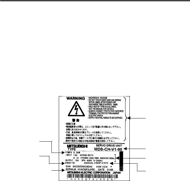
The rating nameplate is attached to the front of the unit.
The following rating nameplate is for the servo drive unit. The same matters are indicated on the power supply unit and spindle drive unit.
Unit Capacity
Global industrial standards
Software version
Serial No., Date of manufacture
Caution statement |
Model |
Input/output condition |
Instruction manual No. |
1-1-3 Power supply unit model
MDS - CH - CV - [ ]
|
|
|
|
|
|
|
|
|
|
|
|
|
|
|
|
|
|
|
|
|
|
|
|
|
|
Rated |
|
|
Rated |
|
|
|
|
|
|
|
|
|
|
|
|
|
||
|
|
|
|
|
|
|
|
|
|
Symbol |
Output |
|
Symbol |
Output |
|
|
|
|
|
|
|
|
|
|
|
[kW] |
|
|
[kW] |
|
|
|
|
|
|
|
|
|
|
37 |
2.2 |
|
260 |
22.0 |
|
|
Power supply unit |
||||||||||||
|
|
|
|
|
|
|
|
|
|
55 |
3.7 |
|
300 |
26.0 |
Series |
|
|
|
|
|
|
|
|
75 |
5.5 |
|
370 |
30.0 |
|
|
|
|
|
|
|
|
|
|
|
110 |
7.5 |
|
450(Note) |
37.0 |
|
|
|
|
|
|
|
|
|
|
150 |
11.0 |
|
550(Note) |
45.0 |
|
|
|
|
|
|
|
|
|
|
185 |
15.0 |
|
750(Note) |
55.0 |
|
|
|
|
|
|
|
|
|
|
220 |
18.5 |
|
|
|
(Note) DC connection bar is required. Always install a large capacity drive unit in the left side of power supply unit, and connect with DC connection bar.
1 - 2

1. Preface
1-1-4 Servo drive unit model
MDS - CH - V1 - [ |
] |
|
|
|
|
|
|
|||||||
|
|
|
|
|
|
|
|
|
|
Rated |
|
|
Rated |
|
|
|
|
|
|
|
|
|
|
Symbol |
Output |
|
Symbol |
Output |
|
|
|
|
|
|
|
|
|
|||||||
|
1-axis servo drive unit |
|
[kW] |
|
|
[kW] |
||||||||
|
|
|
|
|
|
|
05 |
0.5 |
|
70 |
7.0 |
|||
Series |
||||||||||||||
|
|
|
10 |
1.0 |
|
90 |
9.0 |
|||||||
|
|
|
|
|
|
|
|
|||||||
|
|
|
|
|
|
|
|
|
20 |
2.0 |
|
110 |
11.0 |
|
|
|
|
|
|
|
|
|
|
35 |
3.5 |
|
150 |
15.0 |
|
|
|
|
|
|
|
|
|
|
45 |
4.5 |
|
185(Note) |
18.5 |
|
(Note) DC connection bar is required. Always install a large capacity drive unit in the left side of power supply unit, and connect with DC connection bar.
MDS - CH - V2 - [ |
] |
|
|
|
|
|
|||||||
|
Rated |
|
|
Rated |
|||||||||
|
|
|
|
|
|
|
|
|
|
|
|
||
|
|
|
|
|
|
|
|
|
Symbol |
Output |
|
Symbol |
Output |
|
|
|
|
|
|
|
|
|
|||||
|
|
|
|
|
|
|
|
|
|||||
|
|
|
|
|
|
|
|
|
|
[kW] |
|
|
[kW] |
|
2-axis servo drive unit |
0505 |
0.5 / 0.5 |
|
3510 |
3.5 / 1.0 |
|||||||
|
|
|
|
|
|
|
|
|
1005 |
1.0 / 0.5 |
|
3520 |
3.5 / 2.0 |
Series |
|
|
|||||||||||
|
|
1010 |
1.0 / 1.0 |
|
3535 |
3.5 / 3.5 |
|||||||
|
|
|
|
|
|
|
|
|
|
||||
|
|
|
|
|
|
|
|
|
2010 |
2.0 / 1.0 |
|
4520 |
4.5 / 2.0 |
|
|
|
|
|
|
|
|
|
2020 |
2.0 / 2.0 |
|
4535 |
4.5 / 3.5 |
1-1-5 Spindle drive unit model
MDS - CH - SP[ ] - [ |
] |
|
|
|
|
|
|
|
|
|
|
||||||||
|
|
|
|
Cont. |
|
|
|
Cont. |
|
||||||||||
|
|
|
|
|
|
|
|
|
|
|
|
|
|
|
|
|
|
||
|
|
|
|
|
|
|
|
|
|
|
Symbol |
|
Rating |
|
|
Symbol |
Rating |
|
|
Series |
|
|
|
|
|
|
|
|
|
|
[kW] |
|
|
|
[kW] |
|
|||
|
|
|
|
|
|
|
|
|
15 |
|
|
0.75 |
|
|
185 |
15.0 |
|
||
Spindle drive unit |
|
|
|
|
|||||||||||||||
|
|
|
|
|
|
22 |
|
|
1.5 |
|
|
220 |
18.5 |
|
|||||
|
|
|
|
|
|
|
|
|
|
|
|
|
|
||||||
|
|
|
|
|
|
|
|
|
|
|
37 |
|
|
2.2 |
|
|
260 |
22.0 |
|
|
|
|
|
|
|
|
|
|
|
|
55 |
|
|
3.7 |
|
|
300 |
26.0 |
|
|
|
|
|
|
|
|
|
|
|
|
75 |
|
|
5.5 |
|
|
370(Note) |
30.0 |
|
|
|
|
|
|
|
|
|
|
|
|
110 |
|
|
7.5 |
|
|
450(Note) |
37.0 |
|
|
|
|
|
|
|
|
|
|
|
|
150 |
|
|
11.0 |
|
|
550(Note) |
45.0 |
|
|
|
|
|
|
|
|
|
|
|
|
|
|
|
|
|
|
750(Note) |
55.0 |
|
|
|
|
|
|
|
|
|
|
|
|
|
|
|
|
|||||
|
|
|
|
|
|
|
|
|
|
|
Symbol |
|
|
Corresponding spindle motor |
|||||
|
|
|
|
|
|
|
|
|
|
|
|
|
|
|
|||||
|
|
|
|
|
|
|
|
|
|
|
None |
Standard specifications part |
|
|
|||||
|
|
|
|
|
|
|
|
|
|
|
H |
• |
High-speed part: 10000r/min or more |
||||||
|
|
|
|
|
|
|
|
|
|
|
|
• |
C axis detector (1/10000o) |
|
|
||||
|
|
|
|
|
|
|
|
|
|
|
|
|
correspondence: |
|
|
|
|||
|
|
|
|
|
|
|
|
|
|
|
|
|
|
|
|
|
ERM280 (HEIDENHAIN) |
||
|
|
|
|
|
|
|
|
|
|
|
|
• |
IPM spindle motor compatible |
|
|
||||
|
|
|
|
|
|
|
|
|
|
|
|
|
(Conventional SPM class has been |
||||||
|
|
|
|
|
|
|
|
|
|
|
|
|
eliminated.) |
|
|
|
|||
|
|
|
|
|
|
|
|
|
|
|
|
|
|
|
|
|
|
|
|
(Note) DC connection bar is required. Always install a large capacity drive unit in the left side of power supply unit, and connect with DC connection bar.
1 - 3
1. Preface
1-2 Explanation of each part
1-2-1 Explanation of each power supply unit part
<9>
<5>
<6>
<2>
<1>
<9>
<10>
<2>-1 

<3> <1>
Each part name
|
|
|
|
|
|
<8> |
|
|
|
|
|
|
|
Name |
|
|
Description |
|
|||||||
|
|
|
|
|
|
|
|
<1> |
|
|
|
|
TE1 |
|
L1, L2, L3 |
|
Power supply input terminal |
|
|||||||
|
|
|
|
|
|
|
|
|
|
|
|
|
|
|
|
|
|
|
|
||||||
|
|
|
|
|
|
|
|
|
|
|
|
|
|
|
|
|
|
|
(3-phase AC input) |
|
|||||
|
|
|
|
|
|
|
|
|
|
|
|
|
|
|
|
|
|
|
|
|
|
|
|
||
|
|
|
|
|
|
|
|
|
|
|
|
|
<2> |
|
|
|
|
TE2 |
|
|
L+, L– |
|
Converter voltage output terminal |
|
|
|
|
|
|
|
|
|
|
|
|
|
|
|
|
circuit |
|
|
|
|
(DC output) |
|
|||||
|
|
|
|
|
|
|
|
|
|
|
|
|
|
|
|
|
|
|
|
|
|
||||
|
|
|
|
|
|
|
|
|
|
|
|
|
|
|
|
|
|
|
L11, L21 |
|
Control power input terminal (single-phase |
|
|||
|
|
|
|
|
|
|
|
|
|
|
|
|
<3> |
|
Main |
|
TE3 |
|
|
|
|
AC input) |
|
||
|
|
|
|
|
|
<10> |
|
|
|
|
|
|
|
|
MC1 |
|
External contactor control terminal |
|
|||||||
|
|
|
|
|
|
|
|
|
|
|
|
|
|
|
|
|
|
||||||||
|
|
|
|
|
|
|
|
<4> |
|
|
|
|
PE |
|
|
|
|
Grounding terminal |
|
||||||
|
|
|
|
|
|
|
|
|
|
|
|
|
|
|
|
|
|
|
|
|
|
||||
|
|
|
|
|
|
|
|
|
|
|
|
|
|
|
|
|
|
|
|
|
|
|
|
|
|
|
|
|
|
|
|
|
|
|
|
|
|
<10> |
|
|
|
|
--- |
|
CHARGE |
|
TE2 output charging/discharging circuit |
|
|||
|
|
|
|
|
|
<3> |
|
|
|
|
|
|
|
LAMP |
|
indication LED |
|
||||||||
|
|
|
|
|
|
|
|
|
|
|
|
|
|
|
|
|
|
||||||||
|
|
|
|
|
|
|
|
|
|
|
|
|
<5> |
|
|
|
|
CN4 |
|
--- |
|
Servo/spindle communication connector |
|
||
|
|
|
|
|
|
|
|
|
|
|
|
|
|
circuit |
|
|
|
(master) |
|
||||||
|
|
|
|
|
|
|
|
|
|
|
|
|
|
|
|
|
|
|
|
|
|
||||
|
|
|
|
|
|
<4> |
|
|
<6> |
|
|
CN9 |
|
--- |
|
Servo/spindle communication connector |
|
||||||||
|
|
|
|
|
|
|
|
|
|
Control |
|
|
|
|
|
|
(slave) |
|
|||||||
|
|
|
|
|
|
|
|
|
|
|
|
|
<8> |
|
|
SW1 |
|
--- |
|
Power supply setting switch |
|
||||
|
|
|
|
|
|
|
|
|
|
|
|
|
<7> |
|
|
|
|
CN23 |
|
--- |
|
External emergency stop input connector |
|
||
|
|
|
|
|
|
<7> |
|
|
|
|
|
|
|
|
|
|
|
|
|
|
|
||||
|
|
|
|
|
|
|
|
<9> |
|
|
|
|
LED |
|
--- |
|
Power supply status indication LED |
|
|||||||
|
|
|
|
|
|
|
|
|
|
|
|
Precautions |
|
|
|
|
|
|
|||||||
|
|
|
|
|
|
|
|
|
|
|
|
|
CN23 is located at the bottom of the power supply unit. |
||||||||||||
|
|
|
|
|
|
|
|
|
|
|
|
|
Each part name |
|
|
|
|||||||||
|
|
|
|
|
|
|
|
|
|
|
|
|
|
|
|
|
|
|
|
|
|
|
|
||
|
|
|
|
|
|
|
|
|
|
|
|
|
|
|
|
|
|
|
|
Name |
|
Description |
|||
|
|
|
|
|
|
|
|
|
<8> |
|
|
<1> |
|
|
|
TE1 |
|
L1, L2, L3 |
|
Power supply input terminal |
|||||
|
|
|
|
|
|
|
|
|
|
|
|
|
|
|
|||||||||||
|
|
|
|
|
|
|
|
|
|
|
|
|
|
|
|
(3-phase AC input) |
|||||||||
|
|
|
|
|
|
|
|
|
|
|
|
|
|
|
|
|
|
|
|
|
|
||||
|
|
|
|
|
|
|
|
<5> |
|
|
<2> |
-1 |
|
|
|
TE2-1 |
|
L+, L– |
|
Voltage output terminal (DC output) |
|||||
|
|
|
|
|
|
|
|
|
|
|
|
|
|
|
|
CV-450/550/750 |
|||||||||
|
|
|
|
|
|
|
|
|
|
|
|
|
|
|
|
||||||||||
|
|
|
|
|
|
|
|
<6> |
|
|
<2>-2 |
|
circuit |
TE2-2 |
|
L+, L– |
|
Voltage output terminal (DC output) |
|||||||
|
|
|
|
|
|
|
|
|
|
|
|
|
CV-450/550 |
||||||||||||
|
|
|
|
|
|
|
|
|
|
|
|
|
|
|
|
|
|
|
|
|
|
||||
|
|
|
|
|
|
|
|
|
|
|
|
|
|
|
|
|
|
|
|
|
|
|
|
||
|
|
|
|
|
|
|
|
|
|
|
|
|
|
|
|
Main |
|
|
|
L11, L21 |
|
Control power input terminal |
|||
|
|
|
|
|
|
|
|
|
|
|
|
|
<3> |
|
TE3 |
|
|
(single-phase AC input) |
|||||||
|
|
|
|
|
|
|
|
|
|
|
|
|
|
|
|
|
|
||||||||
|
|
|
|
|
|
|
|
|
|
|
|
|
|
|
|
|
|
|
|
||||||
|
|
|
|
|
|
|
|
|
|
|
|
|
|
|
|
|
|
|
|
|
MC1, MC2 |
|
External contactor control terminal |
||
|
|
|
|
|
|
|
|
|
|
<2> |
-2 |
<4> |
|
|
|
PE |
|
|
|
|
Grounding terminal |
||||
|
|
|
|
|
|
|
|
|
|
|
|
|
|
|
|
|
|
|
|
|
|
||||
|
|
|
|
|
|
|
|
|
|
|
|
|
<10> |
|
|
|
--- |
|
|
CHARGE |
|
TE2 output charging circuit indication |
|||
|
|
|
|
|
|
|
|
|
|
|
|
|
|
|
|
|
|
LAMP |
|
LED |
|||||
|
|
|
|
|
|
|
|
|
|
|
|
|
|
|
|
|
|
|
|
|
|
||||
|
|
|
|
|
|
|
|
|
|
|
|
|
<5> |
|
|
|
CN4 |
|
--- |
|
|
Servo/spindle communication connector |
|||
|
|
|
|
|
|
|
|
|
|
|
|
|
|
|
|
|
|
||||||||
|
|
|
|
|
|
|
|
|
|
|
|
|
|
circuit |
|
|
|
(master) |
|||||||
|
|
|
|
|
|
|
|
|
|
|
|
|
|
|
|
|
|
|
|
|
|
||||
|
|
|
|
|
|
|
|
|
|
|
|
|
<6> |
|
CN9 |
|
--- |
|
|
Servo/spindle communication connector |
|||||
<4> |
|
<7> |
|
|
|
|
Control |
|
|
|
|
|
|
(slave) |
|||||||||||
|
|
<8> |
|
SW1 |
|
--- |
|
|
Power supply setting switch |
||||||||||||||||
|
|
|
|
|
|
|
|
|
|
|
|
|
<7> |
|
|
|
CN23 |
|
--- |
|
|
External emergency stop input connector |
|||
|
|
|
|
|
|
|
|
|
|
|
|
|
|
|
|
|
|
|
|
|
|
|
|
|
|
|
|
|
|
|
|
|
|
|
|
|
|
|
|
|
|
|
|
|
|
|
|
|
|
|
|
|
|
|
|
|
|
|
|
|
|
|
|
|
<9> |
|
|
|
LED |
|
--- |
|
|
Power supply status indication LED |
|||
Precautions
CN23 is located at the bottom of the power supply unit.
TE2-2 is used to connect a 30kW or smaller drive unit.
The connector layout will differ according to the units being used. Check each unit outline drawing for details.
1 - 4

1. Preface
1-2-2 Explanation of each servo drive unit part
<15>
<5>
<8>
<9>
<10>
<2>
<1>
<14>
<6>
<7>
<13>
<11>
<12>
<3>
<4>
Each part name
|
|
|
Name |
Description |
<1> |
|
TE1 |
MU, MV, MW |
Motor drive output terminal |
|
LU, LV, LW |
(3-phase AC output) |
||
|
circuit |
|
||
<2> |
TE2 |
L+, L– |
(DC input) |
|
|
|
|
|
Converter voltage input terminal |
|
Main |
|
|
|
<3> |
TE3 |
L11, L21 |
Control power input terminal |
|
(single-phase AC input) |
||||
<4> |
|
PE |
|
Grounding terminal |
|
|
|
|
|
<5> |
|
CN1A |
--- |
NC or upward axis communication |
|
connector |
|||
|
|
|
|
|
<6> |
|
CN1B |
--- |
Battery unit/terminator |
|
Lower axis communication connector |
|||
|
|
|
|
|
<7> |
|
CN4 |
--- |
Power supply communication connector |
<8> |
circuit |
CN9 |
--- |
Maintenance connector (normally not used) |
<9> |
CN2L |
--- |
Motor side detector connection connector |
|
|
(L axis) |
|||
|
|
|
|
|
<11> |
Control |
CN3L |
--- |
Motor side detector connection connector |
Machine side detector connection |
||||
<10> |
|
CN2M |
--- |
(M axis) |
|
|
|
|
|
|
|
|
|
connector (L axis) |
<12> |
|
CN3M |
--- |
Machine side detector connection |
|
connector (M axis) |
|||
|
|
|
|
|
<13> |
|
CN20 |
--- |
Electromagnetic/dynamic brake connector |
<14> |
|
SW1 |
--- |
Axis No. setting switch |
<15> |
|
LED |
--- |
Unit status indication LED |
Precautions
1. The connector names differ for the V1 drive unit. (CN2L/CN3L → CN2/CN3, CN2M/CN3M → Not mounted)
The MU, MV and MW terminals are not provided. The LU, LV and LW terminals are named U, V and W.
1-2-3 Explanation of each spindle drive unit part
<15>
<5>
<8>
<9>
<10>
<2>
<1>
Each part name
|
|
|
|
|
|
|
|
|
|
|
Name |
Description |
|
|
|
|
|
|
|
|
|
<14> |
<1> |
|
TE1 |
U, V, W |
Motor drive output terminal |
|
|
|
|
|
|
|
|
circuit |
(3-phase AC output) |
||||
|
|
|
|
|
|
|
|
|
|
|
|||
|
|
|
|
|
|
<6> |
<2> |
|
TE2 |
L+, L– |
Converter voltage input terminal |
||
|
|
|
|
|
|
|
|||||||
|
|
|
|
|
|
|
|
|
|
|
|
|
(DC input) |
|
|
|
|
<7> |
<3> |
Main |
TE3 |
L11, L21 |
Control power input terminal |
||||
|
|
|
|
|
|
|
|
|
|
|
|
(single-phase AC input) |
|
|
|
|
|
|
|
|
|
|
|
|
|
|
|
|
|
|
|
|
|
|
|
|
<4> |
|
PE |
|
Grounding terminal |
|
|
|
|
<11> |
|
|
|
|
|
||||
|
|
|
|
<5> |
|
CN1A |
--- |
NC or upward axis communication connector |
|||||
|
|
|
|
<12> |
|
|
|
|
|
||||
|
|
|
|
<6> |
|
CN1B |
--- |
Battery unit/terminator lower axis |
|||||
|
|
|
|
|
|
|
|
|
|
communication connector |
|||
|
|
|
|
|
|
|
|
|
|
|
|
|
|
|
|
|
|
<3> |
<7> |
circuit |
CN4 |
--- |
Power supply communication connector |
||||
|
|
|
|
<8> |
CN9 |
--- |
Maintenance connector (normally not used) |
||||||
|
|
|
|
|
|||||||||
|
|
|
|
|
|
|
<4> |
<9> |
Control |
CN5 |
--- |
Internal PLG encoder connection connector |
|
|
|
|
|
|
|
|
<11> |
CN6 |
--- |
Magnetic sensor connection connector |
|||
|
|
|
|
|
|
|
|
|
<10> |
|
CN7 |
--- |
C axis control encoder connection connector |
|
|
|
|
|
|
|
|
|
|
|
|
|
|
|
|
|
|
|
|
|
|
|
|
|
|
|
|
|
|
|
|
|
|
|
|
|
<12> |
|
CN8 |
--- |
CNC connection connector |
|
|
|
|
|
|
|
|
|
|
||||
|
|
|
|
|
|
|
|
|
|
||||
|
|
|
|
|
|
|
|
|
<14> |
|
SW1 |
--- |
Axis No. setting switch |
|
|
|
|
|
|
|
|
|
<15> |
|
LED |
--- |
Unit status indication LED |
Precautions
The connector and terminal block layout will differ according to the units being used.
Check each unit outline drawing for details.
1 - 5
2. Wiring and Connection
2-1 |
Part system connection diagram........................................................................................................ |
2-3 |
|
2-2 |
Main circuit terminal block/control circuit connector .......................................................................... |
2-5 |
|
2-2-1 |
Connector pin assignment .......................................................................................................... |
2-5 |
|
2-2-2 |
Names and applications of main circuit terminal block signals and control circuit connectors .. |
2-7 |
|
2-2-3 |
How to use the control circuit terminal block (MDS-CH-SP-750) ............................................... |
2-8 |
|
2-3 |
NC and drive unit connection........................................................................................................... |
2-10 |
|
2-4 |
Motor and detector connection ........................................................................................................ |
2-11 |
|
2-4-1 Connection of HC-H Series....................................................................................................... |
2-11 |
||
2-4-2 |
Connection of the spindle motor ............................................................................................... |
2-14 |
|
2-4-3 |
Connection of the linear servomotor LM-NP Series.................................................................. |
2-15 |
|
2-5 |
Connection of power supply............................................................................................................. |
2-16 |
|
2-5-1 |
Standard connection ................................................................................................................. |
2-16 |
|
2-5-2 DC connection bar..................................................................................................................... |
2-18 |
||
2-5-3 |
Two-part system control of power supply unit........................................................................... |
2-19 |
|
2-5-4 |
Using multiple power supply units............................................................................................. |
2-20 |
|
2-6 |
Connection of AC reactor................................................................................................................. |
2-21 |
|
2-6-1 |
Features of the AC reactor........................................................................................................ |
2-21 |
|
2-6-2 |
Wiring of AC reactor .................................................................................................................. |
2-21 |
|
2-7 |
Wiring of contactors ......................................................................................................................... |
2-22 |
|
2-7-1 Contactor power ON sequences ............................................................................................... |
2-23 |
||
2-7-2 |
Contactor shutoff sequences .................................................................................................... |
2-23 |
|
2-7-3 |
Contactor control signal (MC1) output circuit............................................................................ |
2-24 |
|
2-8 |
Wiring of the motor brake................................................................................................................. |
2-25 |
|
2-8-1 |
Motor brake release sequence.................................................................................................. |
2-25 |
|
2-8-2 Control during the servo OFF command................................................................................... |
2-25 |
||
2-8-3 Operation sequences when an emergency stop occurs........................................................... |
2-25 |
||
2-8-4 |
Motor brake control connector (CN20) output circuit ................................................................ |
2-26 |
|
2-9 |
Wiring of an external emergency stop ............................................................................................. |
2-27 |
|
2-9-1 |
External emergency stop setting............................................................................................... |
2-27 |
|
2-9-2 |
Operation sequences of CN23 external emergency stop function ........................................... |
2-28 |
|
2-9-3 |
Example of emergency stop circuit ........................................................................................... |
2-29 |
|
2-10 Connecting the Grounding Cable................................................................................................... |
2-30 |
||
2-10-1 Connecting the Frame Ground (FG) ....................................................................................... |
2-30 |
||
2-10-2 |
Grounding cable size............................................................................................................... |
2-30 |
|
2 - 1
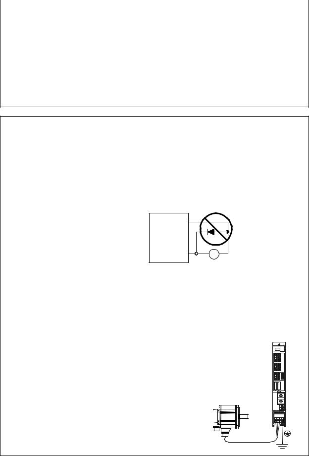
|
|
|
|
|
2. Wiring and Connection |
|
|
|
|
|
|
1. |
Wiring work must be done by a qualified technician. |
||||
2. |
Wait at least 15 minutes after turning the power OFF and check the voltage |
||||
|
|
|
|
|
with a tester, etc., before starting wiring. Failure to observe this could lead to |
|
|
|
DANGER |
|
|
|
|
|
|
electric shocks. |
|
|
|
|
|
||
3.Securely ground the drive units and servo/spindle motor with Class 3 grounding or higher.
4.Wire the drive units and servo/spindle motor after installation. Failure to observe this could lead to electric shocks.
5.Do not damage, apply forcible stress, place heavy items on the cables or get them caught. Failure to observe this could lead to electric shocks.
6.Always insulate the power terminal connection section. Failure to observe this could lead to electric shocks.
1.Correctly and securely perform the wiring. Failure to do so could lead to runaway of the servo/spindle motor.
2.Do not mistake the terminal connections.
Failure to observe this item could lead to ruptures or damage, etc.
3.Do not mistake the polarity ( + , – ). Failure to observe this item could lead to ruptures or damage, etc.
4.Do not mistake the direction of the diodes for the surge absorption installed on the DC relay for the motor brake and contactor (magnetic contactor) control. The signal might not be output when a failure occurs.
 CAUTION
Drive unit
COM (24VDC)
Control output signal |
RA |
5.Electronic devices used near the drive units may receive magnetic obstruction. Reduce the effect of magnetic obstacles by installing a noise filter, etc.
6.Do not install a phase advancing capacitor, surge absorber or radio noise filter on the power line (U, V, W) of the servo/spindle motor.
7.Do not modify this unit.
8.The half-pitch connector (CN1A, etc.) on the front of the drive units have the same shape. If the connectors are connected incorrectly, faults could occur.
Make sure that the connection is correct.
9.When grounding the motor, connect to the protective grounding terminal on the drive units, and ground from the other protective grounding terminal.
(Use one-point grounding)
Do not separately ground the connected motor and drive unit as noise could be generated.
2 - 2

|
|
|
|
2. Wiring and Connection |
|
|
|
|
|
|||
2-1 Part system connection diagram |
|
|
|
|
|
|
|
|||||
Mitsubishi CNC |
|
MDS-CH-CV-[ ] |
MDS-CH-SP-[ ] |
|
|
MDS-CH-V2-[ ] |
|
|
||||
|
SH21 cable |
|
|
|
|
|
|
|
|
|
|
|
|
SV1,2 |
|
|
|
|
|
|
|
|
|
|
|
|
(CSH21) |
|
|
|
|
|
Battery unit |
|
|
|
|
|
|
|
|
|
|
|
|
BT-[ ] |
|
|
|
|
|
|
|
|
|
|
|
|
BT-[ ] |
|
|
|
|
|
|
|
|
|
|
CN1A |
CN1B |
CN1A |
|
CN1A |
CN1B |
|
|
|
|
|
|
|
|
|
SH21 cable |
|
|
|
|
Machine side |
|
|
|
|
|
|
|
|
|
|
|
CNV13 cable |
detector |
|
|
|
|
CN4 |
CN4 |
CN8 |
|
|
CN4 |
CN3M |
|
|
|
|
|
|
|
|
|
|
|||||
|
|
|
|
|
|
CN7 |
|
|
|
|
|
Machine side |
|
External emergency |
|
|
|
|
|
|
|
CNV13 cable |
detector |
||
|
CN23 CN9 |
|
|
|
|
|
|
|||||
|
CN9 |
|
|
|
CN9 |
CN3L |
|
|||||
|
stop |
|
|
|
|
|
|
|||||
|
|
|
|
|
|
CN6 |
|
|
|
|
CNV12 cable |
|
|
|
|
|
|
|
|
CNP5S cable |
|
CN20 |
CN2L |
|
|
|
AC reactor |
Magnetic |
|
|
|
CN5 |
|
|
|
|||
|
|
|
|
|
|
|
|
CNV12 cable |
|
|||
Circuit breaker |
CH-AL[ ] K |
contactor |
|
|
|
|
|
|
|
|
|
|
CH-AL[ ]K |
|
TE1 |
|
|
|
|
|
|
CN2M |
|
|
|
|
|
|
|
|
TE1 |
|
|
|
|
|
||
R |
|
|
L1 |
|
|
|
|
|
|
|
|
|
|
|
|
|
U |
|
|
|
TE1 |
|
|
||
|
|
|
|
|
|
|
|
|
|
|
||
S |
|
|
L2 |
|
|
|
M |
|
|
MU |
|
|
|
|
|
|
V |
|
|
|
|
|
|||
|
|
|
|
|
|
|
|
|
M |
|
||
|
|
|
|
|
TE2 |
|
3~ |
|
TE2 |
MV |
|
|
T |
|
|
L3 |
TE2 |
|
|
PLG |
3~ |
|
|||
|
|
W |
|
|
|
|||||||
|
|
|
|
|
|
|
|
|
|
Motor side |
||
|
|
|
|
L+ |
L+ |
|
|
|
L+ |
MW |
|
|
|
|
|
|
|
|
|
|
detector |
||||
|
|
|
|
|
|
|
|
|
|
|
|
|
|
Ground |
|
TE3 |
L- |
L- |
|
|
|
L- |
LU |
|
|
|
|
MC |
MC1 |
|
|
|
|
|
|
LV |
|
M |
|
|
|
|
|
TE3 |
|
|
|
TE3 |
|
3~ |
|
|
|
|
L11 |
|
|
|
|
|
|
|||
|
|
|
|
L11 |
|
|
|
L11 |
LW |
|
Motor side |
|
|
|
|
|
|
|
|
|
|
||||
|
|
|
|
|
|
|
|
|
|
|
|
detector |
|
|
|
L21 |
|
L21 |
|
|
|
L21 |
|
|
|
Main circuit |
|
|
|
|
|
|
|
|
|
|||
|
|
|
|
|
|
|
|
|
|
|
||
Control circuit |
|
|
|
|
|
|
|
|
|
|
|
|
|
|
|
|
Ground |
|
Ground |
|
|
|
Ground |
|
|
(Note 1) The total length of the SH21 cable must be within 30m.
(Note 2) The connection method will differ according to the used motor.
(Note 3) When not using an absolute position detector, connect the terminal connector (R-TM). (Note 4) The main circuit ( ) and control circuit ({) are safely separated.
2 - 3
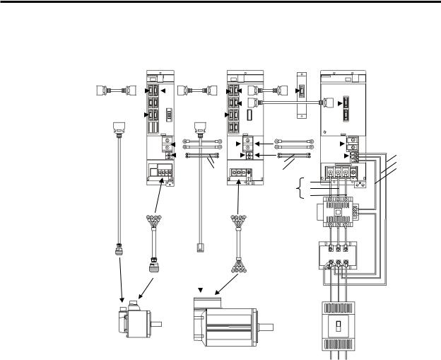
2. Wiring and Connection
Example of actual wiring
|
|
|
|
|
|
|
|
|
|
|
|
|
|
Battery |
|
|
|
|
|
|
Servo drive unit |
|
|
Spindle drive unit |
|
|
unit |
Power supply unit |
|||||||||
|
|
|
|
|
|
|
||||||||||||
SH21 |
SH21 |
|
|
|
|
SH21 |
|
|
|
|
|
|
||||||
NC controller |
|
|
|
|
|
|
|
|
|
|
|
|
|
|
|
|
||
|
|
|
|
|
|
|
|
|
|
|
SH21 |
|
|
|
||||
|
|
|
|
|
|
|
|
|
|
|
|
|
|
|
|
|||
|
|
|
|
|
|
|
|
|
|
|
|
|
|
|
|
|
|
|
|
|
|
|
|
|
|
|
|
|
|
|
|
|
|
|
|
|
|
|
|
|
|
L+ |
||||
|
|
|
|
L- |
|
|
||
|
|
|
|
|
||||
|
|
|
|
|
|
|
|
|
|
|
|
|
L11 |
||||
|
|
|
|
L21 |
||||
CNV12 cable |
|
|
CNP5S cable |
|||||
DRSV cable (Drive line) |
|
|
|
|
|
|
|
DRSP cable (Drive line) |
|
|
|
||||||
|
|
|
|
|
|
|
|
|
Servo motor
Spindle motor
|
L+ |
||||
|
L- |
|
|
L11 |
|
|
|
||||
|
|
|
|
|
|
L11 |
|
|
|
|
L21 |
L21 |
|
|
|
|
MC1 |
DRTE1 |
L1 |
|
L2 |
||
cable |
||
L3 |
||
|
||
Contactor |
||
AC reactor
Breaker
L1 L2 L3
Note)
The main circuit cable wiring must be prepared by the user.
The wiring to the grounding cable is not shown. Refer to section "2-10 Wiring the Grounding Cable".
2 - 4

|
|
|
|
|
2. Wiring and Connection |
|
2-2 Main circuit terminal block/control circuit connector |
||||||
|
|
|
|
|
Do not apply a voltage other than that specified in Instruction Manual on each |
|
|
|
|
CAUTION |
|||
|
|
|
|
terminal. Failure to observe this item could lead to rupture or damage, etc. |
|
|
|
|
|
|
|||
|
|
|||||
|
|
|
|
|
|
|
2-2-1 Connector pin assignment
Power supply unit
Unit |
MDS-CH-CV-37 to |
MDS-CH-CV-450 |
|
|
MDS-CH-CV-750 |
||
|
MDS-CH-CV-370 |
MDS-CH-CV-550 |
|
Terminal |
|
||
|
|
|
Terminal
position
<1> TE1
assignment |
<2> TE2 |
Terminal specification/Pin |
|
<3> TE3 |
|
|
|
|
|
|
|
|
<2> |
|
<2>1 |
|
|
<2>2 |
|
|
|
|
|
<2> |
|
|
|
|
|
|
|
|
<3> |
|
|
<1> |
<3> |
|
|
|
|
<3> |
|
|
|
|
<1> |
||
|
<1> |
|
|
|
|
|
|
|
<1> |
<1> |
L1 |
L2 |
L3 |
<1> |
L1 |
L2 |
L3 |
|
L1 L2 L3 |
|
PE |
|
37-185 |
220-370 |
|
|
450 |
550 |
|
|
750 |
Screw size |
M5×12 |
M8×14 |
|
Screw size |
M8×16 |
M10×20 |
|
Screw size |
M10×20 |
Tightening torque |
2.0Nm |
6.0Nm |
|
Tightening torque |
6.0Nm |
11.0Nm |
|
Tightening torque |
11.0Nm |
<2> |
<2>1 |
L+ |
<2> |
|
|
|
|
|
|
|
|
|
|
|
|
|
L– |
|
|
|
|
L+ |
|
450 |
550 |
|
L+ |
|
L– |
|
|
L– |
||
|
Screw size |
M10×20 M10×20 |
|
|||
|
|
Tightening torque |
11.0Nm 11.0Nm |
|
|
|
|
<2>2 |
L+ |
|
|
|
|
|
37-185 220-370 |
|
|
|
750 |
|
|
|
|
|
|
||
Screw size |
M6×15 M6×15 |
|
L– |
|
Screw size |
M10×20 |
Tightening torque |
3.0Nm 3.0Nm |
|
|
|
Tightening torque |
11.0Nm |
|
|
|
450 |
550 |
|
|
|
|
Screw size |
M6×16 M6×16 |
|
|
|
|
|
Tightening torque |
3.0Nm 3.0Nm |
|
|
|
<3> |
<3> |
L1 L12 MC1 |
<3> |
L11 L12 |
MC1 |
|
L11
L21
MC1
|
|
|
|
|
L12 L22 MC2 |
L12 L22 |
MC2 |
|
||||
|
|
|
|
|
|
|
|
|
|
|
|
|
|
|
37-185 |
220-370 |
|
|
450 |
550 |
|
|
750 |
|
|
|
Screw size |
M4×10 |
M4×10 |
|
Screw size |
M4×8 |
|
M4×8 |
|
Screw size |
M4×8 |
|
|
Tightening torque |
1.2Nm |
1.2Nm |
|
Tightening torque |
1.2Nm |
|
1.2Nm |
|
Tightening torque |
1.2Nm |
|
|
|
|
|
|
|
|
|
|
|
|
||
|
Refer to PE terminal of TE1. |
|
|
450 |
|
550 |
|
|
750 |
|
||
|
|
|
|
|
Screw size |
M8×16 |
M10×20 |
|
Screw size |
M10×20 |
|
|
|
|
|
|
|
Tightening torque |
6.0Nm |
11.0Nm |
|
Tightening torque |
11.0Nm |
|
|
2 - 5

2. Wiring and Connection
Servo/spindle drive unit
Unit |
MDS-CH-V-150 or less |
|
MDS-CH-V1-185 |
|
|
MDS-CH-V2 Series |
MDS-CH-SP-370 |
MDS-CH-SP-750 |
|
|
MDS-CH-SP-300 or less |
|||
Terminal |
|
MDS-CH-SP-450/550 |
|
|
|
|
|
Terminal
position
|
<1> |
TE1 |
|||||
assignment |
|
|
|
|
|
|
|
|
|
|
|
|
|
||
specification/Pin |
<2> |
TE2 |
|||||
|
|||||||
Terminal |
|
|
|
|
|
|
|
<3> |
TE3 |
||||||
|
|||||||
|
|
|
|
|
|
|
|
|
|
|
|
|
|
|
|
|
|
|
|
|
|
|
|
|
|
|
|
|
|
|
|
|
|
|
|
|
|
<2> |
|
<2> |
|
|
|
|
<2> |
|
|
|
|
<2> |
|
|
|
|
|
<3> |
|
|
<3> |
|
|
|
|
|
|
<3> |
<1> |
|
|
||
<1> |
|
|
<1> |
|
|
<1> |
<3> |
|
|
|
|
|
|||
<1> |
|
<1> |
MU MV MW |
<1> |
|
|
|
U V W |
|
|
|
U |
V |
W |
|
|
|
|
|
|
|||
|
PE |
|
LU LV LW |
PE |
|
|
|
|
|
|
|
|
|
Corresponding |
V1- |
10-35 |
45-90 |
110-150 |
|
|
|
370 |
450/550/750 |
V2- 1010-4535 |
---- |
---- |
|
|
|
||||
unit |
SP- |
15-37 |
55-185 |
220-300 |
|
Screw size |
|
M8×16 |
M10×20 |
|
|
|
|||||||
Screw size |
M4×10 |
M5×12 |
M8×14 |
|
Tightening torque |
6.0Nm |
11.0Nm |
||
Tightening torque |
1.2Nm |
2.0Nm |
6.0Nm |
|
|
|
|
|
|
<2> |
|
|
L+ |
|
<2> |
|
|
L+ |
|
|
|
|
|
|
|
|
|
||
|
|
|
|
|
|
|
|
|
|
|
|
|
L– |
|
|
|
|
L– |
|
|
|
|
|
|
|
|
|
|
|
|
|
|
V1/V2/SP |
|
|
|
|
370 |
450/550/750 |
|
Screw size |
M6×16 |
|
|
Screw size |
|
M10×20 |
M10×20 |
|
Tightening torque |
3.0Nm |
|
|
Tightening torque |
11.0Nm |
11.0Nm |
|||
<3> |
|
|
|
|
<3> |
L11 |
L21 |
|
|
|
|
|
|
|
|
|
|||
|
|
|
L11 |
|
|
|
|
|
|
|
|
|
L21 |
|
|
|
|
|
|
|
|
|
V1/V2/SP |
|
|
|
370/450/550 |
750 |
|
|
Screw size |
M4×10 |
|
|
Screw size |
|
M4×8 |
Refer to "2-2-3". |
|
Tightening torque |
1.2Nm |
|
|
Tightening torque |
|
1.2Nm |
Refer to "2-2-3". |
||
|
Refer to PE terminal of TE1. |
|
|
|
|
370 |
450/550/750 |
||
|
|
|
|
|
|
|
|
||
|
|
|
|
|
|
Screw size |
|
M8×16 |
M10×20 |
|
|
|
|
|
|
Tightening torque |
|
6.0Nm |
11.0Nm |
2 - 6

2. Wiring and Connection
2-2-2 Names and applications of main circuit terminal block signals and control circuit connectors
The following table shows the details for each terminal block signal.
|
Name |
Signal name |
Description |
|||||||
L1 . L2 . L3 |
Main circuit |
Main circuit power supply input terminal |
||||||||
power supply |
Connect a 3-phase 380 to 480VAC, 50/60Hz power supply. |
|||||||||
|
|
|
|
|
|
|
|
|||
L11 |
|
. L21 |
|
Control circuit power supply input terminal |
||||||
|
Control circuit |
Connect a single-phase 380 to 480VAC, 50/60Hz power supply. |
||||||||
(L12 |
|
. L22) |
power supply |
Connect the same power supply phase for L11 and L12, and L21 and |
||||||
|
|
|
|
|
|
|
|
|
L22. |
|
|
MC1 |
Contactor |
Contactor control terminal |
|||||||
|
The MC1 terminal has the same phase as L21. Connect to a different |
|||||||||
|
(MC2) |
control |
||||||||
|
phase than the phase connected to L21. (Connect MC2 with L21.) |
|||||||||
|
|
|
|
|
|
|
|
|
||
U . V . W |
Motor output |
Servo/spindle motor power output terminal |
||||||||
The servo/spindle motor power terminal (U, V, W) is connected. |
||||||||||
|
|
|
|
|
|
|
|
|
||
LU |
. LV . LW |
Motor output |
Servo motor power output terminal (L-axis/M-axis) |
|||||||
MU |
. MV . MW |
The servo/spindle motor power terminal (U, V, W) is connected. |
||||||||
|
|
|
|
|
|
|
|
Protective |
Grounding terminal |
|
|
|
|
|
|
|
|
|
The servomotor/spindle motor grounding terminal is connected and |
||
|
|
|
|
|
|
|
|
grounding (PE) |
||
|
|
|
|
|
|
|
|
grounded. |
||
|
|
|
|
|
|
|
|
|
||
1.Always use one AC reactor per power supply unit. Failure to observe this could lead to unit damage.
CAUTION |
2. When sharing a breaker for several power supply units, of a short-circuit |
|
fault occurs in a small capacity unit, the breaker could trip. This can be |
||
|
||
|
hazardous, so do not share the breaker. |
3. Be sure to use the breaker of proper capacity for each Power Supply Unit.
2 - 7
2. Wiring and Connection
2-2-3 How to use the control circuit terminal block (MDS-CH-SP-750)
The control power for the 75kW spindle unit is not connected to the terminal block, so wire according to the following instructions.
<1> Treatment of wire end |
Length to peel |
|
|
|
|
Single wire: Peel the wire sheath, and use the wire.
(Wire size: 0.25 to 2.5 mm2)
Approx. 10mm
Stranded wire: Peel the wire sheath, and then twist the core wires. Take care to prevent short circuits with the
neighboring poles due to the fine strands of the core wires. Solder plating onto the core wire section could cause a contact defect and must be avoided. (Wire size: 0.25 to 2.5 mm2)
Use a bar terminal and bundle the strands. (Made by Phoenix contact)
Bar terminal for one wire |
Bar terminal for two wires |
(Bar terminal phenol with insulation sleeve) |
(TWIN phenol with insulation sleeve) |
|
|
Wire size |
Bar terminal type |
|
||
[mm2] |
AWG |
For one wire |
For two wires |
|
|
|
|
|
|
0.25 |
24 |
AI0.25-6YE |
– |
|
AI0.25-8YE |
|
|||
|
|
|
|
|
0.5 |
20 |
AI0.5-6WH |
– |
|
AI0.5-8WH |
|
|||
|
|
|
|
|
0.75 |
18 |
AI0.75-6GY |
AI-TWIN2×0.75-8GY |
|
AI0.75-8GY |
AI-TWIN2×0.75-10G |
|
||
|
|
|
Y |
|
1 |
18 |
AI1-6RD |
AI-TWIN2×1-8RD |
|
AI1-8RD |
AI-TWIN2×1-10RD |
|
||
|
|
|
||
1.5 |
16 |
AI1.5-6BK |
AI-TWIN2×1.5-8BK |
|
AI1.5-8BK |
AI-TWIN2×1.5-12BK |
|
||
|
|
|
||
2.5 |
14 |
AI2.5-8BU |
AI-TWIN2×2.5-10BU |
|
AI2.5-8BU-1000 |
AI-TWIN2×2.5-13BU |
|
||
|
|
|
||
Crimping tool
CRIMPFOX-UD6
<2> Connection method
Insert the core wire section of the wire into the opening, and tighten with a screwdriver so that the wire does not come out. (Tightening torque: 0.5 to 0.6 N•m) When inserting the wire into the opening, make sure that the terminal screw is sufficiently loose. When using a wire that is 1.5 mm2 or less, two wires can be inserted into one opening.
2 - 8
Loading...