


MELDAS Series
MDS-CH-SP PLG Adjustment(BNP-B8827-016H)
USA-99671 -024*
MITSUBISHI ELECTRIC AUTOMATION
USA

List of Revisions
Rev |
Date of Revision |
Detail |
Author |
* |
05/3/04 |
First Edition Created |
TSS |
|
|
|
|
|
|
|
|
|
|
|
|
|
|
|
|
|
|
|
|
|
|
|
|
|
|
|
|
|
|
|
|
|
|
|
|
|
|
|
|
|
|
|
|
|
|
|
|
|
|
|
|
|
|
|
|
|
|
|
|
|
|
|
|
|
|
|
|
|
|
|
|
|
|
|
|
|
|
|
|
|
|
|
|
|
|
|
|
|
|
|
|
|
|
|
|
|
|
|
|
|
|
|
|
|
|
|
|
|
|
|
|
|
|
|
|
|
|
|
|
|
|
|
|
|
|
|
|
|
|
|
|
|
|
|
|
|
|
|
|
|
|
|
|
|
|
|
|

AC SPINDLE
MDS-CH-SP SERIES
PLG ADJUSTMENT PROCEDURES
BNP-B8827-016-H (ENG)
Introduction
Thank you for selecting the Mitsubishi numerical control unit.
This instruction manual describes the handling and caution points for using this AC servo/spindle.
Incorrect handling may lead to unforeseen accidents, so always read this instruction manual thoroughly to ensure correct usage.
Make sure that this instruction manual is delivered to the end user. Always store this manual in a safe place.
This manual explains the methods of adjusting the PLG for the MDS-CH Series. Always refer to each CNC Specifications before starting use.
Notes on Reading This Manual
(1)Since the description of this specification manual deals with NC in general, for the specifications of individual machine tools, refer to the manuals issued by the respective machine manufacturers. The "restrictions" and "available functions" described in the manuals issued by the machine manufacturers have precedence to those in this manual.
(2)This manual describes as many special operations as possible, but it should be kept in mind that items not mentioned in this manual cannot be performed.
i
Precautions for safety
Please read this manual and auxiliary documents before starting installation, operation, maintenance or inspection to ensure correct usage. Thoroughly understand the device, safety information and precautions before starting operation.
The safety precautions in this instruction manual are ranked as "DANGER", "WARNING" and "CAUTION".
DANGER

 WARNING
CAUTION
When the operator could be subject to fatalities or serious injuries if handling is mistaken.
When a dangerous situation, or fatal or serious injuries may occur if handling is mistaken.
When a dangerous situation may occur if handling is mistaken leading to medium or minor injuries, or physical damage.
Note that some items described as |
|
|
CAUTION |
may lead to major results depending on |
|
|
|||
|
|
|
|
|
the situation. In any case, important information that must be observed is described.
The numeric control unit is configured of the control unit, operation board, servo drive unit, spindle drive unit, power supply, servomotor and spindle motor, etc.
In this manual, the following items are generically called the "motor".
•Servomotor
•Spindle motor
In this manual, the following items are generically called the "unit".
•Servo drive unit
•Spindle drive unit
•Power supply unit
ii

 DANGER
No corresponding items in this manual.
 WARNING
1. Electric shock prevention
Do not open the front cover while the power is ON or during operation. Failure to observe this could lead to electric shocks.
Do not operate the unit with the front cover removed. The high voltage terminals and charged sections will be exposed, and can cause electric shocks.
Do not remove the front cover even when the power is OFF unless carrying out wiring work or periodic inspections. The inside of the units is charged, and can cause electric shocks.
Wait at least 15 minutes after turning the power OFF before starting wiring or inspections. Failure to observe this could lead to electric shocks.
Always ground the unit and motor following the standards set forth by each country. (In Japan, grounding resistance 10Ω or less is the standard.)
Wiring and inspection work must be done by a qualified technician.
Wire the servo drive unit and servomotor after installation. Failure to observe this could lead to electric shocks.
Do not touch the switches with wet hands. Failure to observe this could lead to electric shocks.
Do not damage, apply forcible stress, place heavy items on the cables or get them caught. Failure to observe this could lead to electric shocks.
CAUTION
1. Fire prevention
Install the units, motors and regenerative resistor on noncombustible material. Direct installation on combustible material or near combustible materials could lead to fires.
Shut off the power on the power supply unit side if a fault occurs in the units. Fires could be caused if a large current continues to flow.
Provide a sequence that shut off the power at the regenerative resistor error signal-ON when using the regenerative resistor. The regenerative resistor could abnormally overheat and cause a fire due to a fault in the regenerative transistor, etc.
iii
CAUTION
2. Injury prevention
Do not apply a voltage other than that specified in Instruction Manual on each terminal. Failure to observe this item could lead to ruptures or damage, etc.
Do not mistake the terminal connections. Failure to observe this item could lead to ruptures or damage, etc.
Do not mistake the polarity ( + , – ). Failure to observe this item could lead to ruptures or damage, etc.
Do not touch the radiation fin on unit back face, regenerative resistor or motor, etc., or place parts (cables, etc.) while the power is turned ON or immediately after turning the power OFF. These parts may reach high temperatures, and can cause burns.
Structure the cooling fan on the unit back face so that it cannot be touched after installation. Touching the cooling fan during operation could lead to injuries.
3. Various precautions
Observe the following precautions. Incorrect handling of the unit could lead to faults, injuries and electric shocks, etc.
(1) Transportation and installation
Correctly transport the product according to its weight.
Use the motor's hanging bolts only when transporting the motor. Do not transport the motor when it is installed on the machine.
Do not stack the products above the tolerable number.
Do not hold the cables, axis or detector when transporting the motor.
Do not hold the connected wires or cables when transporting the units.
Do not hold the front cover when transporting the unit. The unit could drop.
Follow this Instruction Manual and install the unit or motor in a place where the weight can be borne.
Do not get on top of or place heavy objects on the unit.
Always observe the installation directions of the units or motors.
Secure the specified distance between the units and control panel, or between the servo drive unit and other devices.
Do not install or run a unit or motor that is damaged or missing parts.
Do not block the intake or exhaust ports of the motor provided with a cooling fan.
Do not let foreign objects enter the units or motors. In particular, if conductive objects such as screws or metal chips, etc., or combustible materials such as oil enter, rupture or breakage could occur.
The units and motors are precision devices, so do not drop them or apply strong impacts to them.
iv
CAUTION
 Store and use the units under the following environment conditions.
Environment |
Conditions |
|||
|
|
|||
Unit |
Motor |
|||
|
|
|||
|
|
|
|
|
|
During operation |
0°C to 55°C |
0°C to 40°C |
|
Ambient |
(with no freezing) |
(with no freezing) |
||
|
||||
temperature |
|
|
|
|
During storage/ |
–15°C to 70°C |
–15°C to 70°C |
||
|
transportation |
(with no freezing) |
(with no freezing) |
|
|
During operation |
90%RH or less |
20% to 90%RH |
|
Ambient |
(with no dew condensation) |
(with no dew condensation) |
||
|
||||
humidity |
|
|
|
|
During storage/ |
90%RH or less |
90% RH or less |
||
|
transportation |
(with no dew condensation) |
(with no dew condensation) |
|
|
|
Indoors (where unit is not |
subject to direct sunlight), |
|
Atmosphere |
|
with no corrosive gas, combustible gas, oil mist, |
||
|
|
dust or conductive particles |
||
|
|
Operation/storage: 1000m or less above sea level |
||
Altitude |
|
Transportation: 10000m or less above sea level |
||
|
(Specified value does not apply only |
|||
|
|
|||
|
|
during transport by air.) |
||
|
|
|
||
Vibration |
|
To follow each unit and motor specifications |
||
|
|
|
|
|
Securely fix the servomotor to the machine. Insufficient fixing could lead to the servomotor slipping off during operation.
Always install the servomotor with reduction gear in the designated direction. Failure to do so could lead to oil leaks.
Structure the rotary sections of the motor so that it can never be touched during operation. Install a cover, etc., on the shaft.
When installing a coupling to a servomotor shaft end, do not apply an impact by hammering, etc. The detector could be damaged.
Do not apply a load exceeding the tolerable load onto the servomotor shaft. The shaft could break.
If the unit has been stored for a long time, always check the operation before starting actual operation. Please contact the Service Center or Service Station.
v
CAUTION
(2) Wiring
Correctly and securely perform the wiring. Failure to do so could lead to runaway of the motor.
Do not install a condensing capacitor, surge absorber or radio noise filter on the output side of the drive unit.
Correctly connect the output side of the drive unit (terminals U, V, W). Failure to do so could lead to abnormal operation of the motor.
Always install an AC reactor for each power supply unit.
Always install an appropriate breaker for each power supply unit. The breaker cannot be shared by several units.
Direct application of a commercial power supply to the motor could cause burning. Always connect the motor to the drive unit's output terminals (U, V, W).
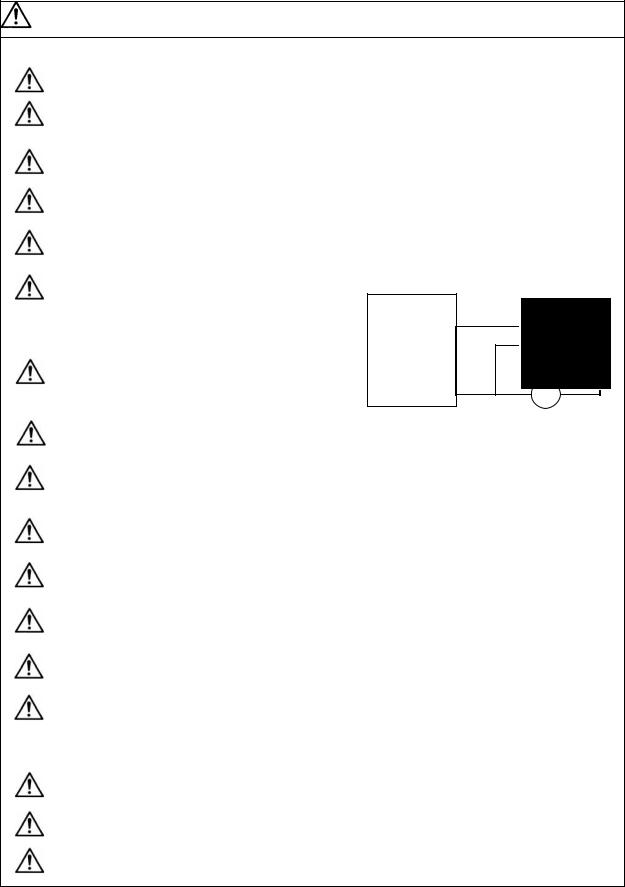
When using an inductive load such as a relay, always connect a diode as a noise measure parallel to the load.
Drive unit |
Diode reverse direction |
COM |
|
(24VDC) |
|
Control output |
RA |
signal |
When using a capacitance load such as a lamp, always connect a protective resistor as a noise measure serial to the load.
Do not reverse the direction of a diode which connect to a DC relay for the control output signals to suppress a surge. Connecting it backwards could cause the drive unit to malfunction so that signals are not output, and emergency stop and other safety circuits are inoperable.
Do not connect/disconnect the cables connected between the units while the power is ON.
Securely tighten the cable connector fixing screw or fixing mechanism. An insecure fixing could cause the cable to fall off while the power is ON.
When using a shielded cable instructed in the connection manual, always ground the cable with a cable clamp, etc.
Always separate the signals wires from the drive wire and power line.
Use wires and cables that have a wire diameter, heat resistance and flexibility that conforms to the system.
(3) Trial operation and adjustment
Check and adjust each program and parameter before starting operation. Failure to do so could lead to unforeseen operation of the machine.
Do not make remarkable adjustments and changes as the operation could become unstable.
The usable motor and unit combination is predetermined. Always check the models before starting trial operation.
vi
 Loading...