


Revision A:
•3. SPECIFICATION and 4. OUTLINES AND DIMENSIONS have been modified.
Please void OBH752.
INDOOR UNIT
SERVICE MANUAL
No. OBH752
REVISED EDITION-A
Models
MFZ-KJ09NA- U1
MFZ-KJ12NA- U1
MFZ-KJ15NA- U1
MFZ-KJ18NA- U1
Outdoor unit service manual MUFZ-KJ•NAHZ Series (OBH753) MXZ-C•NA, MXZ-C•NAHZ Series
(OBH702, OCH573)
CONTENTS
1. TECHNICAL CHANGES ··································· 3
2. PART NAMES AND FUNCTIONS····················· 4
3. SPECIFICATION················································ 5
4. OUTLINES AND DIMENSIONS ························ 7
5. WIRING DIAGRAM············································ 8
6. REFRIGERANT SYSTEM DIAGRAM ··············· 9
7. SERVICE FUNCTIONS ··································· 10
8. MICROPROCESSOR CONTROL ··················· 12
9. TROUBLESHOOTING····································· 21
10. DISASSEMBLY INSTRUCTIONS···················· 36
PARTS CATALOG (OBB752)
NOTE:
•This service manual describes technical data of the indoor units.
•RoHS compliant products have <G> mark on the spec name plate.
For servicing of RoHS compliant products, refer to the RoHS Parts List.
Use the specified refrigerant only
Never use any refrigerant other than that specified.
Doing so may cause a burst, an explosion, or fire when the unit is being used, serviced, or disposed of. Correct refrigerant is specified in the manuals and on the spec labels provided with our products.
We will not be held responsible for mechanical failure, system malfunction, unit breakdown or accidents caused by failure to follow the instructions.
Revision A:
• 3. SPECIFICATION and 4. OUTLINES AND DIMENSIONS have been modified.
OBH752A |
2 |
|
1 
 TECHNICAL CHANGES
MFZ-KJ09NA- U1 MFZ-KJ12NA- U1 MFZ-KJ15NA- U1 MFZ-KJ18NA- U1
1. New model
OBH752A |
3 |
|

2 
 PART NAMES AND FUNCTIONS
MFZ-KJ09NA MFZ-KJ12NA MFZ-KJ15NA MFZ-KJ18NA
Air outlet |
Horizontal vane |
0XOWL ÀRZ YDQH |
Vertical vane |
$LU FOHDQLQJ ¿OWHU |
Fan guard |
|
|
(Anti-allergy enzyme filter, option) |
|
|
Panel |
Front panel |
|
$LU ¿OWHU 1DQR SODWLQXP ¿OWHU
Display and operation section (When the front panel is opened)
E.O |
Emergency operation |
SW |
switch |
|
Remote control receiving section 

Operation indicator lamp 
ACCESSORIES
|
|
|
MFZ-KJ09NA MFZ-KJ12NA |
|
|
|
MFZ-KJ15NA MFZ-KJ18NA |
|
|
|
|
|
Drain hose |
|
1 |
|
Remote controller holder |
1 |
|
|
Fixing screw for |
3.5 x 16 mm (Black) |
2 |
|
Pipe cover |
|
1 |
|
Band |
|
2 |
|
Battery (AAA) for remote controller |
2 |
|
|
Indoor unit mounting bracket |
1 |
|
|
Fixing screw for |
4 x 25 mm |
5 |
|
Wood screw for the indoor unit fixation |
4 |
|
|
Washer of |
|
4 |
|
Felt tape (Used for left or left-rear piping) |
1 |
|
|
Wireless remote controller |
1 |
|
OBH752A |
4 |
|
3 |
|
|
SPECIFICATION |
|
|
|
|
|
|
|
||
1. Single connection |
|
|
|
|
|
|
|
|
|
|||
|
|
|
|
|
|
|
|
|
|
|||
Indoor model |
|
|
MFZ-KJ09NA |
|
MFZ-KJ12NA |
|
MFZ-KJ15NA |
|
MFZ-KJ18NA |
|||
Power supply |
V, phase, Hz |
|
208/230, 1, 60 |
|
|
|||||||
Max. fuse size (time delay)/ Disconnect switch |
A |
|
15 |
|
|
20 |
||||||
Airflow |
|
COOL Dry |
CFM |
417 - 360 - 272 - 198 - 138 |
|
431 - 392 - 311 - 254 - 198 |
491 - 420 - 328 - 254 - 198 |
|||||
Super High - High - Med. - |
(Wet) |
(354 - 306 - 231 - 168 - 117) |
|
(366 - 333 - 264 - 216 - 168) |
(417 - 357 - 279 - 216 - 168) |
|||||||
Low - Quiet |
|
HEAT Dry |
CFM |
417 - 328 - 254 - 191 - 138 |
|
470 - 399 - 328 - 268 - 212 |
||||||
Sound level |
|
Cooling |
dB (A) |
46 - 41 - 34 - 27 - 21 |
|
47 - 43 - 38 - 33 - 28 |
50 - 45 - 39 - 33 - 28 |
|||||
Super High - High - Med. - |
|
|
|
|
|
|
|
|
|
|||
Heating |
dB (A) |
46 - 40 - 34 - 27 - 21 |
|
49 - 45 - 40 - 35 - 29 |
49 - 45 - 40 - 35 - 29 |
|||||||
Low - Quiet |
|
|
||||||||||
Cond. drain connection O.D. |
|
in. |
|
|
|
5/8 |
|
|
||||
|
|
|
|
W |
|
|
29-17/32 |
|
|
|||
Dimensions |
|
D |
in. |
|
8-15/32 |
|
|
|||||
|
|
|
|
H |
|
|
23-5/8 |
|
|
|||
Weight |
|
|
Ib. |
|
|
|
33 |
|
|
|||
External finish |
|
|
|
|
White |
|
|
|||||
Control voltage (by built-in transformer) |
|
|
|
12 - 24 VDC |
|
|
||||||
NOTE: Test conditions are based on ARI 210/240.
2. Multi connection
Indoor model |
|
|
MFZ-KJ09NA |
|
MFZ-KJ12NA |
|
MFZ-KJ15NA |
|
MFZ-KJ18NA |
Power supply |
V, phase, Hz |
|
208/230, 1, 60 |
|
|
||||
Max. fuse size (time delay)/ Disconnect switch |
A |
|
15 |
|
|
20 |
|||
Airflow |
COOL Dry |
CFM |
275 - 251 - 208 173 - 138 |
|
374 - 328 - 282 - 237 - 198 |
||||
Super High - High - Med. - |
(Wet) |
(234 - 213 - 177 - 147 - 117) |
|
(318 - 279 - 240 - 201 - 168) |
|||||
Low - Quiet |
HEAT Dry |
CFM |
343 - 219 - 180 - 159 - 138 |
|
470 - 325 - 290 - 254 - 212 |
||||
Sound level |
Cooling |
dB (A) |
38 - 34 - 30 - 25 - 21 |
|
43 - 40 - 36 - 31 - 28 |
||||
Super High - High - Med. - |
|
|
|
|
|
|
|
|
|
Heating |
dB (A) |
41 - 32 - 27 - 24 - 21 |
|
49 - 39 - 36 - 34 - 29 |
|||||
Low - Quiet |
|
||||||||
Cond. drain connection O.D. |
|
in. |
|
|
|
5/8 |
|
|
|
|
W |
|
|
29-17/32 |
|
|
|||
Dimensions |
D |
in. |
|
8-15/32 |
|
|
|||
|
H |
|
|
23-5/8 |
|
|
|||
Weight |
|
Ib. |
|
|
|
33 |
|
|
|
External finish |
|
|
|
|
White |
|
|
||
Control voltage (by built-in transformer) |
|
|
|
12 - 24 VDC |
|
|
|||
NOTE: Test conditions are based on ARI 210/240.
OBH752A |
5 |
|

3-1. OPERATING RANGE
(1) POWER SUPPLY
|
Rated voltage |
Guaranteed voltage (V) |
||||||
|
208/230 V |
Min. 187 208 |
230 Max. 253 |
|||||
Indoor unit |
1 phase |
|||||||
|
|
|
|
|
|
|||
|
60 Hz |
|
|
|
|
|
|
|
|
|
|
|
|
|
|
||
|
|
|
|
|
|
|
|
|
(2) OPERATION
Mode |
Condition |
|
|
Intake air temperature (°F) |
|
|
|
Indoor |
|
|
Outdoor |
||||
|
|
DB |
|
WB |
DB |
|
WB |
|
Standard temperature |
80 |
|
67 |
95 |
|
— |
Cooling |
Maximum temperature |
90 |
|
73 |
115 |
|
— |
Minimum temperature |
67 |
|
57 |
14 |
|
— |
|
|
|
|
|||||
|
Maximum humidity |
78% |
|
|
— |
||
Heating |
Standard temperature |
70 |
|
60 |
47 |
|
43 |
Maximum temperature |
80 |
|
67 |
75 |
|
65 |
|
|
Minimum temperature |
70 |
|
60 |
-13 |
|
-14 |
3-2. OUTLET AIR SPEED AND COVERAGE
1. Single connection
Model |
Mode |
Function |
Airflow |
Air speed |
Coverage (ft.) |
|
|
|
|
(CFM) |
(ft./s.) |
|
|
MFZ-KJ09NA |
HEAT |
Dry |
417 |
20.3 |
29.6 |
|
|
Dry |
417 |
20.3 |
29.6 |
||
MFZ-KJ12NA |
COOL |
|||||
Wet |
354 |
17.2 |
25.3 |
|||
|
|
|||||
|
HEAT |
Dry |
470 |
22.9 |
33.3 |
|
MFZ-KJ15NA |
COOL |
Dry |
431 |
21.0 |
30.6 |
|
|
Wet |
366 |
17.8 |
26.2 |
||
|
|
|||||
|
HEAT |
Dry |
470 |
22.9 |
33.3 |
|
MFZ-KJ18NA |
COOL |
Dry |
491 |
23.9 |
34.8 |
|
|
Wet |
417 |
20.3 |
29.7 |
||
|
|
|||||
2. Multi connection |
|
|
|
|
||
Model |
Mode |
Function |
Airflow |
Air speed |
Coverage (ft.) |
|
|
|
|
(CFM) |
(ft./s.) |
|
|
MFZ-KJ09NA |
HEAT |
Dry |
343 |
16.7 |
24.5 |
|
|
Dry |
275 |
13.4 |
19.8 |
||
MFZ-KJ12NA |
COOL |
|||||
Wet |
234 |
11.4 |
16.9 |
|||
|
|
|||||
MFZ-KJ15NA |
HEAT |
Dry |
470 |
22.9 |
33.3 |
|
|
Dry |
374 |
18.2 |
26.7 |
||
MFZ-KJ18NA |
COOL |
|||||
Wet |
318 |
15.5 |
22.8 |
|||
|
|
|||||
●The air coverage is the figure up to the position where the air speed is 1 ft./s., when air is blown out horizontally from the unit properly at the High speed position.
The coverage should be used only as a general guideline since it varies according to the size of the room and furniture arranged inside the room.
OBH752A |
6 |
|

4 
 OUTLINES AND DIMENSIONS
MFZ-KJ09NA MFZ-KJ12NA MFZ-KJ15NA MFZ-KJ18NA
Unit: inch
OBH752A |
7 |
|

5 |
WIRING DIAGRAM |
MFZ-KJ09NA MFZ-KJ12NA MFZ-KJ15NA MFZ-KJ18NA |
|
OBH752A |
8 |
|

6 
 REFRIGERANT SYSTEM DIAGRAM
MFZ-KJ09NA MFZ-KJ12NA MFZ-KJ15NA MFZ-KJ18NA |
Unit: inch (mm) |
Refrigerant pipe  3/8 (
3/8 ( 9.52) (MFZ-KJ09/12)
1/2 ( 12.7) (MFZ-KJ15/18)
(with heat insulator)
Indoor |
|
|
heat |
|
|
exchanger |
Distributor |
Flared connection |
Indoor coil thermistor RT12, RT14, RT15 (main) RT13 (sub)
Room temperature |
|
|
|
|
|
|
|
|
|
|||||
thermistor |
|
|
|
|
|
|
|
|
|
|||||
RT11 |
|
|
|
|
Flared connection |
|||||||||
|
|
|||||||||||||
|
|
|||||||||||||
|
|
|
|
|
|
|||||||||
|
|
|
|
|
|
|
|
|
|
|
|
|
|
|
|
|
|
|
|
|
|
|
|
|
|
|
|
|
|
Refrigerant flow in cooling |
|
|
|
|
|
Refrigerant pipe 1/4 ( 6.35) |
||||||||
|
|
|
|
|
(with heat insulator) |
|||||||||
Refrigerant flow in heating
OBH752A |
9 |
|
7 
 SERVICE FUNCTIONS
MFZ-KJ09NA MFZ-KJ12NA MFZ-KJ15NA MFZ-KJ18NA
7-1. TIMER SHORT MODE
•For service, the following set time can be shortened by bridging the timer short mode point on the electronic control P.C. board. (Refer to 9-7.)
•The set time for the ON/OFF timer can be reduced to 1 second for each minute.
•After the breaker is turned on, the time for starting the compressor, which normally takes 3 minutes, can be reduced to 3 seconds. Restarting the compressor, which takes 3 minutes, cannot be reduced.
7-2. HOW TO SET REMOTE CONTROLLER EXCLUSIVELY FOR A PARTICULAR INDOOR UNIT
A maximum of 4 indoor units with wireless remote controllers can be used in a room.
To operate the indoor units individually with each remote controller, assign a number to each remote controller according to the number of the indoor unit.
This setting can be set only when all the following conditions are met:
•The remote controller is powered OFF.
•Weekly timer is not set.
•Weekly timer is not being edited.
1. How to modify the electronic control P.C. board
Turn OFF the power supply before modification. To assign a number to each indoor unit , cut off “JR05” and “JR06” on the electronic control P.C. board as shown in Table 1. (Refer to 9-7.)
Table 1
|
JR05 |
JR06 |
|
|
|
|
|
Indoor electronic |
|||||
|
|
|
|
|
|
control P.C. Board |
|||||||
Unit No. 1 |
No modification |
No modification |
|
|
|
|
|
||||||
|
|
|
|
|
|
|
Fuse (F11) |
||||||
Unit No. 2 |
Cut off JR05 |
No modification |
VARISTOR (NR11) |
|
|
|
|
|
|
|
JR05 |
||
|
|
|
|
|
|
||||||||
|
|
|
|
|
|||||||||
|
|
|
|
|
|
|
|
|
|
|
|
|
|
Unit No. 3 |
No modification |
Cut off JR06 |
R111 |
|
|
|
|
|
|
|
|
|
JR06 |
|
|
|
|
|
|
|
|
|
|||||
Unit No. 4 |
Cut off JR05 |
Cut off JR06 |
|
|
|
|
|
|
|||||
|
|
|
|
|
|
|
|
||||||
|
|
|
|
|
|
|
|
|
|
|
|||
2. How to set the remote controller |
|
CN211 |
|
|
|
|
|
|
CN151 |
||||
|
|
|
|
||||||||||
|
|
|
|
|
|
|
|
|
|
||||
|
|
|
|
|
|
|
|
|
|
||||
|
|
|
|
|
|
|
|
|
|
|
|
||
|
|
|
|
|
|
|
|
|
|
|
|
||
(1)Hold down  button on the remote controller for 2 seconds to enter the pairing mode.
(2)Press  button again and assign a number to each remote controller.
Each press of  button advances the number in the following order: 1 → 2 → 3 → 4.
(3)Press  button to complete the pairing setting.
After the setting, turn ON the power supply and with the remote controller headed towards the indoor unit, press the STOP/OPERATE (OFF/ON) button. If 1 or 2 beeps are heard from the indoor unit, the setting is completed correctly. The remote controller that first sends a signal to an indoor unit will be regarded as the remote controller for the indoor unit.
Once they are set, the indoor unit will only receive the signal from the assigned remote controller afterwards.
OBH752A |
10 |
|
7-3. AUTO RESTART FUNCTION
When the indoor unit is controlled with the remote controller, the operation mode, the set temperature, and the fan speed are memorized by the indoor electronic control P.C. board. “AUTO RESTART FUNCTION” automatically starts operation in the same mode just before the shutoff of the main power.
Operation
 If the main power has been cut, the operation settings remain.
 After the power is restored, the unit restarts automatically according to the memory. (However, it takes at least 3 minutes for the compressor to start running.)
How to disable “AUTO RESTART FUNCTION”
 Turn off the main power for the unit.
 Cut the Jumper wire to JR77 on the indoor electronic control P.C. board. (Refer to 9-7.)
CN201 F11
L101

 JR77
JR77
|
C111 |
|
|
|
T111 |
|
|
|
||||
|
|
|
|
|
|
|
|
|
||||
CN211 |
|
|
|
|
|
|
|
|
|
|
||
|
|
|
|
|
|
|
|
|
|
|||
|
|
|
|
|
|
|
|
|
|
|
|
|
CN111 |
CN104 |
CN105 |
|
|
|
|||||||
|
|
|
CN123 |
|||||||||
|
|
|
|
|
|
|
|
|
|
|||
|
|
|
|
|
|
|
|
|
|
|
|
|
|
|
|
|
|
|
|
|
|
|
|
|
|
|
|
|
|
|
|
|
|
|
|
|
|
|
|
|
|
|
|
|
|
|
|
|
|
|
|
NOTE:
•The operation settings are memorized when 10 seconds have passed after the indoor unit was operated with the remote controller.
•If main power is turned OFF or a power failure occurs while AUTO START/STOP timer is active, the timer setting is cancelled.
•If the unit has been off with the remote controller before power failure, the auto restart function does not work as the power button of the remote controller is off.
•To prevent breaker OFF due to the rush of starting current, systematize other home appliance not to turn ON at the same time.
•When some air conditioners are connected to the same supply system, if they are operated before power failure, the starting current of all the compressors may flow simultaneously at restart.
Therefore, the special counter measures are required to prevent the main voltage-drop or the rush of the starting current by adding to the system that allows the units to start one by one.
OBH752A |
11 |
|

8 
 MICROPROCESSOR CONTROL
MFZ-KJ09NA MFZ-KJ12NA MFZ-KJ15NA MFZ-KJ18NA
WIRELESS REMOTE CONTROLLER
Operation display section 


TEMPERATURE buttons
Signal transmitting section
Distance of signal : About 20 ft. (6 m)
Beep(s) is (are) heard from the indoor unit when the signal is received.
OPERATION SELECT button |
FAN SPEED CONTROL button |
|
POWERFUL button |
||
ECONO COOL button |
||
|
||
SLEEP button |
VANE CONTROL button |
|
SMART SET button |
|
|
|
TIME, TIMER set buttons |
|
|
FORWARD button |
|
|
BACKWARD button |
|
STOP/OPERATE |
WEEKLY TIMER |
|
(OFF/ON) button |
set buttons |
|
|
||
|
RESET button |
|
Indication of |
CLOCK button |
|
Lid |
||
remote controller |
||
Slide the lid down |
||
model is on back |
||
to open the remote |
||
|
||
|
controller. Slide it down |
|
|
further to get to the |
|
|
weekly timer buttons. |
NOTE: Last setting will be stored after the unit is turned OFF with the remote controller. Indoor unit receives the signal of the remote controller with beeps.
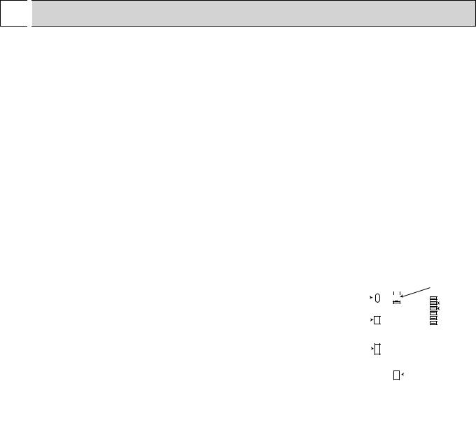
INDOOR UNIT DISPLAY SECTION
Operation Indicator lamp
The operation indicator at the right side of the indoor unit indicates the operation state. •The following indication applies regardless of shape of the indication.
Indication |
Operation state |
Room temperature |
|
The unit is operating to |
About 4 °F (2°C) or more |
|
away from set tempera- |
|
|
reach the set temperature |
|
|
ture |
|
|
|
|
|
The room temperature is |
About 2 to 4 °F (1 to 2°C) |
|
approaching the set tem- |
|
|
from set temperature |
|
|
perature |
|
|
|
|
|
Standby mode (only during |
— |
|
multi system operation) |
|
|
|
|
|
|
|
Lighted
Blinking
Not lighted
OBH752A |
12 |
|

8-1. COOL ( ) OPERATION
(1)Press STOP/OPERATE (OFF/ON) button.
OPERATION INDICATOR lamp of the indoor unit turns on with a beep tone.
(2)Select COOL mode with OPERATION SELECT button.
(3)Press TEMPERATURE buttons TEMP  or
or  button to select the desired temperature. The setting range is 61 - 88°F (16
-31°C).
1.Coil frost prevention
The compressor operational frequency is controlled by the temperature of the indoor heat exchanger to prevent the coil from frosting.
When the temperature of indoor heat exchanger becomes too low, the coil frost prevention mode works.
The indoor fan operates at the set speed and the compressor stops. This mode continues until the temperature of indoor heat exchanger rises.
2. Low outside temperature operation
When the outside temperature is lower, low outside temperature operation starts, and the outdoor fan slows or stops.
3. Indoor fan speed control
When the thermostat turns OFF, the indoor fan operates at the setting fan speed.
8-2. DRY ( ) OPERATION
(1)Press STOP/OPERATE (OFF/ON) button.
OPERATION INDICATOR lamp of the indoor unit turns on with a beep tone.
(2)Select DRY mode with OPERATION SELECT button.
(3)The set temperature is determined from the initial room temperature.
1. Coil frost prevention
Coil frost prevention works the same way as that in COOL mode. (8-1.1.)
2. Low outside temperature operation
Low outside temperature operation works the same way as that in COOL mode. (8-1.2.)
3. Indoor fan speed control
Indoor fan speed control works the same way as that in COOL mode. (8-1.3.) However in AUTO setting, the fan speed changes.
8-3. FAN ( ) OPERATION
(1) Press STOP/OPERATE (OFF/ON) button.
OPERATION INDICATOR lamp of the indoor unit turns on with a beep tone.
(2)Select FAN mode with OPERATION SELECT button.
(3)Select the desired fan speed. When AUTO, it becomes Low. Only indoor fan operates.
Outdoor unit does not operate.
NOTE: Temperature cannot be set during FAN mode.
8-4. HEAT ( ) OPERATION
(1) Press STOP/OPERATE (OFF/ON) button.
OPERATION INDICATOR lamp of the indoor unit turns on with a beep tone.
(2)Select HEAT mode with OPERATION SELECT button.
(3)Press TEMPERATURE buttons TEMP  or
or  button to select the desired temperature. The setting range is 61 - 88°F (16
-31°C).
1. Cold air prevention control
When the compressor is not operating or is starting, and the temperature of indoor heat exchanger and/or the room temperature is low or when defrosting is being done, the indoor fan will stop or rotate in Very Low speed.
2. High pressure protection
The compressor operational frequency is controlled by the temperature of the indoor heat exchanger to prevent the condensing pressure from increasing excessively.
When the temperature of indoor heat exchanger becomes too high, the high pressure protection works. This mode continues until the temperature of indoor heat exchanger falls.
3. Defrosting
Defrosting starts when the temperature of outdoor heat exchanger becomes too low.
The compressor stops once, the indoor/outdoor fans stop, the 4-way valve reverses, and the compressor re-starts. This mode continues until the temperature of outdoor heat exchanger rises or the fixed time passes.
OBH752A |
13 |
|
 Loading...