


 Loading...
Electronic Multi-Measuring Instrument
MODEL
ME96SSHB-MB
User's Manual: Detailed Edition
●Before use, you should read this user’s manual carefully to properly operate this instrument.
Be sure to forward the manual to the end user.

Check your delivery
The following table shows a list of the instrument accessories.
When unpacking your package, check all the contents.
Contents |
Quantity |
|
|
Specification |
||
User’s Manual |
1 |
|
|
|
|
|
|
|
|
|
|
||
|
|
|
|
|
||
(Digest version) |
|
|
|
|
|
|
|
|
|
|
|
|
|
|
|
|
|
|
|
|
|
|
|
|
A3 size |
||
|
|
|
|
|
|
|
Attachment lug |
2 |
|
|
|
|
|
(with a screw) |
|
|
|
|
|
|
|
|
|
|
|
|
|
|
|
|
|
|
|
|
Optional plug-in module
The following table shows a list of optional plug-in modules available for this product.
Installing the optional plug-in module enables various input or output. If you need it, consult with your supplier. ME-4201-NS96, ME-0052-NS96, and ME-0040C-NS96, which are optional plug-in modules for ME96NSR and ME96NSR-MB, are not available for ME96SSHB-MB.
|
|
|
|
|
|
|
|
|
|
I/O specifications |
|
|
|
|
|
|
|
|
||||
|
Model type |
|
|
Analog |
|
|
Pulse/Alarm |
|
|
Digital |
|
|
Digital |
|
|
Communication |
|
|
Logging |
|
|
|
|
|
|
|
output |
|
|
output |
|
|
input |
|
|
output |
|
|
|
|
function |
|
|
||
|
|
|
|
|
|
|
|
|
|
|
|
|
|
|
|
|
|
|||||
|
ME-4210-SS96B |
|
4 ch |
|
2 ch |
|
1 ch |
|
|
|
|
|
|
|
|
|||||||
|
ME-0040C-SS96 |
|
|
|
|
|
4 ch |
|
|
|
|
CC-Link |
|
|
|
|||||||
|
ME-0052-SS96 |
|
|
|
|
|
5 ch |
|
2 ch |
|
|
|
|
|
|
|||||||
|
ME-0000MT-SS96 |
|
|
|
|
|
|
|
|
|
MODBUS |
|
|
|
||||||||
|
|
|
|
|
|
|
TCP |
|
|
|||||||||||||
|
|
|
|
|
|
|
|
|
|
|
|
|
|
|
|
|
|
|
|
|
||
|
ME-0000BU-SS96 |
|
|
|
|
|
|
|
|
|
|
|
|
6 items |
|
|||||||
|
|
|
|
|
|
|
|
|
|
|
|
|
|
|||||||||
|
I/O parts |
|
|
|
|
Specifications |
|
|
|
|
|
Model type |
|
|||||||||
Analog output |
Output: 4 mA to 20 mA |
|
|
|
|
|
|
|
ME-4210-SS96B |
|
||||||||||||
Load resistance: 600 Ω or less |
|
|
|
|
|
|
|
|
||||||||||||||
|
|
|
|
|
|
|
|
|
|
|
|
|
|
|
|
|||||||
|
|
|
|
|
|
|
|
|
|
|
|
|
|
|
|
|
||||||
Pulse/Alarm output |
No-voltage a-contact |
|
|
|
|
|
|
|
ME-4210-SS96B |
|
||||||||||||
Contact capacity: 35 V DC, 0.1 A or less |
|
|
|
|
|
|
||||||||||||||||
|
|
|
|
|
|
|
|
|
|
|
|
|
|
|||||||||
|
|
|
|
|
|
|||||||||||||||||
|
|
|
Contact capacity: 24 V DC (19 V DC to 30 V DC), 7 mA |
ME-4210-SS96B |
|
|||||||||||||||||
Digital input |
or less |
|
|
|
|
|
|
|
|
|
|
|
ME-0040C-SS96 |
|
||||||||
|
|
|
Input pulse width: 30 ms or more |
|
|
|
|
|
ME-0052-SS96 |
|
||||||||||||
Digital output |
No-voltage a-contact |
|
|
|
|
|
|
|
ME-0052-SS96 |
|
||||||||||||
Contact capacity: 35 V DC, 0.2 A or less |
|
|
|
|
|
|
||||||||||||||||
|
|
|
|
|
|
|
|
|
|
|
|
|
|
|||||||||
|
|
|
|
|
|
|
|
|
|
|
|
|
|
|
|
|
|
|
|
|
|
|
In this manual, the operation is also explained when the optional plug-in module is installed.
1

Features
The instrument measures load status by wiring the secondary sides of VT (Voltage Transformer) and CT (Current Transformer) in the power receiving and distribution system and displays various measured values.
The instrument supports highly accurate measurement (accuracy of current/voltage: 0.1%; active energy: class 0.5S) and high-order harmonic measurement (1st to 31st).
Active energy can be measured by dividing into three time periods such as peak, off-peak, and shoulder. (Periodic Active Energy)
This instrument enables measurement of active energy/reactive energy/ apparent energy for any period (interval). (Rolling demand active power/Rolling demand reactive power/Rolling demand apparent power)
The password protection prevents undesired setting change and measured data deletion.
The transmission function (MODBUS RTU communication, CC-Link communication, or MODBUS TCP commination) transmits measured data to superior monitoring systems.
*CC-Link communication is available when ME-0040C-SS96 (optional plug-in module) is installed. *MODBUS TCP commination is available when ME-0040C-SS96 (optional plug-in module) is installed.
The logging function enables to back up measured values in a SD memory card even when a MODBUS RTU communication error occurs.
*It is available when ME-0000BU-SS96 (optional plug-in module) is installed.
This instrument itself can output key measuring elements such as current, voltage, active power, power factor, and active energy at the power receiving point by installing an optional plug-in module with analog output/pulse output function. It is ideal for remote monitoring.
*It is available when ME-4210-SS96B (optional plug-in module) is installed
The built-in logging function provides the logging of measured values, alarm logs, and system logs into this instrument.
The standard complies with the requirements of CE marking, UL standards, KC mark, and FCC/IC.
The support function for checking input wiring enables to determine the wiring condition in the test mode. When either a voltage input or current input are incorrectly wired, the incorrect wiring part is displayed on the screen and it also shows a current phase angle, a voltage phase angle, and each value of active power, voltage, and current.
Trademark
MODBUS is a trademark of Schneider Electric USA Inc.
Other company and product names herein are trademarks or registered trademarks of their respective owners. In the text, trademark symbols such as ‘TM’ and ‘®’ may not be written.
2

Table of Contents
Check your delivery ................................................................................................................................................ |
1 |
||||
Optional plug-in module.......................................................................................................................................... |
1 |
||||
Features.................................................................................................................................................................. |
|
|
|
2 |
|
Trademark .............................................................................................................................................................. |
|
|
|
2 |
|
Table of Contents ................................................................................................................................................... |
3 |
||||
Safety Precautions.................................................................................................................................................. |
5 |
||||
EMC Directive Instruction ....................................................................................................................................... |
9 |
||||
Table for measuring element code ....................................................................................................................... |
10 |
||||
1. |
Name and Function of Each Section............................................................................................................... |
11 |
|||
|
Name of Each Part ................................................................................................................................ |
11 |
|||
|
LCD Function......................................................................................................................................... |
13 |
|||
|
Function of Operation Buttons............................................................................................................... |
14 |
|||
|
LED Display of Optional Plug-in Module ............................................................................................... |
16 |
|||
2. |
Each Mode Function........................................................................................................................................ |
17 |
|||
3. |
How to Set up .................................................................................................................................................. |
18 |
|||
|
Setting Flow........................................................................................................................................... |
18 |
|||
|
Setting Menu 1: Basic Setup (Settings for Phase Wire System, Display Pattern, VT/Direct Voltage, |
||||
|
and CT Primary Current) ....................................................................................................................... |
20 |
|||
|
Setting Menu 2: Communication Settings (MODBUS RTU Communication Settings) ......................... |
24 |
|||
|
Setting Menu 2: Communication Settings (CC-Link Communication Settings) .................................... |
25 |
|||
|
Setting Menu 2: Communication Settings (MODBUS TCP Communication Settings).......................... |
26 |
|||
|
Setting Menu 3: Display Settings (Settings for Active/Reactive Energy and Harmonic Measurement)28 |
||||
|
Setting Menu 4: LCD Settings (Settings for Model Display, Version Display, Backlight, and Display |
|
|||
|
Update Time)......................................................................................................................................... |
30 |
|||
|
Setting Menu 5: Pulse/Alarm Settings (Settings for Upper/Lower Limit Alarm, Motor Starting Current |
|
|||
|
Mask Function, and Pulse Output) ........................................................................................................ |
31 |
|||
|
Setting Menu 6: Built-in Logging Settings ............................................................................................. |
36 |
|||
|
Setting Menu 6: Analog Output Settings ............................................................................................... |
39 |
|||
|
Setting Menu 6: Optional Logging settings............................................................................................ |
43 |
|||
|
Setting Menu 7: Settings for Periodic Active Energy, Rolling Demand, and Digital Input/Output......... |
45 |
|||
|
Setting Menu 8: Special Settings (Settings for Operating Time, IEC Mode, and CO2 equivalent)........ |
47 |
|||
|
Setting Menu CL: Present Time Settings .............................................................................................. |
49 |
|||
|
Setting Confirmation Menu 1 to 9: Confirming the Settings in the Setting Menu 1 to 8 and 9 Test |
|
|||
|
Mode...................................................................................................................................................... |
51 |
|||
|
Initialization of Related Items by Changing a Setting............................................................................ |
52 |
|||
|
Initialization of All Settings..................................................................................................................... |
53 |
|||
|
Settings for Special Display Pattern P00............................................................................................... |
54 |
|||
|
Example for Easy Setup ........................................................................................................................ |
56 |
|||
4. How to Use Test Mode .................................................................................................................................... |
58 |
||||
|
Test Menu 1: Communication Test ....................................................................................................... |
59 |
|||
|
Test Menu 2: Alarm Output/Digital Output Test .................................................................................... |
60 |
|||
|
Test Menu 3: Zero/Span Adjustment for Analog Output ....................................................................... |
61 |
|||
|
Test Menu 4: Analog Output Test ......................................................................................................... |
62 |
|||
|
Test Menu 5: Pulse Output Test............................................................................................................ |
63 |
|||
|
Test Menu 6: Function for Determining Incorrect Wiring....................................................................... |
64 |
|||
|
4.6.1. |
Incorrect Wiring Patterns Detected by |
Pattern display of incorrect wiring |
................................ |
67 |
5. |
.........................................................................................................................................................Operation |
|
|
|
70 |
|
Basic Operation ..................................................................................................................................... |
70 |
|||
|
5.1.1. |
How to Switch the Measurement Screen....................................................................................... |
70 |
||
|
5.1.2. |
How to Switch Phase Display ........................................................................................................ |
70 |
||
|
5.1.3. |
How to Display the Cyclic Mode .................................................................................................... |
71 |
||
|
5.1.4. |
Harmonics Display......................................................................................................................... |
72 |
||
|
5.1.5. |
Maximum/Minimum Value Display................................................................................................. |
73 |
||
|
5.1.6. |
How to Display Maximum/Minimum Value .................................................................................... |
73 |
||
|
5.1.7. |
How to Clear Maximum/Minimum Value........................................................................................ |
73 |
||
|
5.1.8. |
Active Energy/Reactive Energy/Apparent Energy Display ............................................................ |
74 |
||
|
5.1.9. |
How to Change the Display Digit of Active/Reactive/Apparent Energy......................................... |
74 |
||
|
5.1.10. How to Reset Active/Reactive/Apparent Energy to Zero............................................................... |
75 |
|||
|
5.1.11. How to Measure Reactive Energy (2 quadrant/4 quadrant measurement .................................. |
75 |
|||
|
5.1.12. Each Measuring Item Display during Power Transmission ........................................................... |
76 |
|||
|
5.1.13. |
Demand Time Period and Demand Value of Current demand...................................................... |
76 |
||
3

Table of Contents
|
Usage Depending on the Application (Alarm, Periodic Active Energy, Rolling Demand, Operating |
|
|
|
Time, Password, etc.)............................................................................................................................ |
77 |
|
|
5.2.1. |
Upper/Lower Limit Alarm Display and Action ................................................................................ |
77 |
|
5.2.2. |
How to Cancel the Upper/Lower Limit Alarm................................................................................. |
79 |
|
5.2.3. |
How to Stop Backlight Blinking Caused by the Upper/Lower Limit Alarm Generation.................. |
79 |
|
5.2.4. |
Upper/Lower Limit Alarm Item on the Alarm Contact .................................................................... |
79 |
|
5.2.5. |
Periodic Active Energy Display...................................................................................................... |
80 |
|
5.2.6. |
How to Reset Periodic Active Energy to Zero ............................................................................... |
80 |
|
5.2.7. |
Rolling Demand Display and Calculation....................................................................................... |
81 |
|
5.2.8. |
Rolling Demand Predict Value....................................................................................................... |
82 |
|
5.2.9. |
Rolling Demand Time Period Adjustment...................................................................................... |
82 |
|
5.2.10. |
How to Clear the Rolling Demand Peak Value.............................................................................. |
82 |
|
5.2.11. |
Operating Time Display ................................................................................................................. |
83 |
|
5.2.12. |
How to Reset Operating Time to Zero........................................................................................... |
83 |
|
5.2.13. |
CO2 Equivalent Display.................................................................................................................. |
83 |
|
5.2.14. |
How to Clear the CO2 Equivalent................................................................................................... |
83 |
|
5.2.15. |
Digital Input/Output Status Display and Action.............................................................................. |
84 |
|
5.2.16. |
How to Cancel the Latch for Digital Input ...................................................................................... |
84 |
|
5.2.17. |
How to Prevent Maximum Value Update by Motor Starting Current ............................................. |
84 |
|
5.2.18. |
Password Protection Setting.......................................................................................................... |
85 |
|
5.2.19. |
Built-in Logging Function ............................................................................................................... |
86 |
6. |
Others .............................................................................................................................................................. |
|
87 |
|
Display Pattern List................................................................................................................................ |
87 |
|
|
Standard Value...................................................................................................................................... |
90 |
|
|
Measuring Items and the Corresponding Display/Output ..................................................................... |
94 |
|
|
Instrument Operation............................................................................................................................. |
96 |
|
|
Troubleshooting..................................................................................................................................... |
97 |
|
7. |
Installation...................................................................................................................................................... |
|
100 |
|
Dimensions.......................................................................................................................................... |
100 |
|
|
How to Install ....................................................................................................................................... |
102 |
|
|
7.2.1. |
Mounting Hole Dimensions.......................................................................................................... |
102 |
|
7.2.2. |
Mounting Position ........................................................................................................................ |
102 |
|
7.2.3. |
Mounting and Fixing..................................................................................................................... |
102 |
|
7.2.4. |
Optional Plug-in Module Installation ............................................................................................ |
102 |
|
How to Connect Wiring........................................................................................................................ |
103 |
|
|
7.3.1. |
Specifications on the Applicable Electrical Wire.......................................................................... |
103 |
|
7.3.2. |
Wiring of this Instrument .............................................................................................................. |
103 |
|
7.3.3. |
Wiring of the Optional Plug-in Module ......................................................................................... |
103 |
|
7.3.4. |
Check the Connection.................................................................................................................. |
103 |
|
Wiring Diagram.................................................................................................................................... |
105 |
|
|
How to insert/remove SD memory card .............................................................................................. |
113 |
|
8. |
Specifications................................................................................................................................................. |
114 |
|
|
Product Specifications ......................................................................................................................... |
114 |
|
|
Compatible Standards ......................................................................................................................... |
117 |
|
|
MODBUS RTU Communication Specifications ................................................................................... |
117 |
|
|
CC-Link Communication Specifications for optional plug-in module .................................................. |
118 |
|
|
MODBUS TCP Communication Specifications for optional plug-in module ....................................... |
118 |
|
|
Logging Specifications for optional plug-in module............................................................................. |
119 |
|
|
Setting Table (Factory Default Settings and Customer’s Notes Settings) .......................................... |
120 |
|
9. |
Appendix........................................................................................................................................................ |
|
123 |
|
ME96SS Calculation Method (3-phase Unbalanced System with Neutral) ........................................ |
123 |
|
|
Optional parts ...................................................................................................................................... |
124 |
|
|
A List of Examples for Incorrect Wiring Display .................................................................................. |
125 |
|
|
9.3.1. |
3-phase 4-wire System ................................................................................................................ |
125 |
|
9.3.2. |
3-phase 3-wire System ................................................................................................................ |
134 |
|
9.3.3. |
1-phse 3-wire System .................................................................................................................. |
141 |
4

Safety Precautions
Before use, read these instructions carefully to properly operate the instrument. Be sure to follow the precautions described here for personnel and product safety. Keep this manual ready to hand and accessible for future use at all times.
Be sure to forward the manual to the end user.
If you consider using the instrument for a special purpose such as nuclear power plants, aerospace, medical care, or passenger vehicles, consult with our sales representative.
The instructional icon in the manual is described as follows.
The caution icon ( ) on the main unit indicates that incorrect handling may cause hazardous conditions. Always follow the subsequent instructions (
 ) because
they are important to personal safety. Failure to follow them may result in an CAUTION electric shock, a fire, erroneous operation, or damage to the instrument. If the
instrument is used in a manner not specified by the manufacturer, the protection provided by the instrument may be impaired.
The terminals of auxiliary power (MA, MB) and voltage input (P1, P2, P3, PN) have
 CAUTION hazards of electric shock, explosion, or arc flash. Turn off the power supply of auxiliary power and input circuit and then handle the instrument.
■Precautions on use environment and conditions Do not use the instrument in the following places:
Failure to follow the instruction may cause a malfunction or reduced product life time.
The ambient temperature exceeds the range -5°C to +55°C.
The average daily temperature exceeds +35°C.
The relative humidity exceeds the range 0 to 85% RH, or condensing.
The altitude exceeds 2000 m.
Pollution Degree: more than 2 *Note 1
Exposed to much dust, corrosive gas, salty environment, or oil mist
Transient over voltage: 4000 V *Note 1
Exposed to excessive vibration or impact
Exposed to rain or water drops
Exposed to direct sunlight
Pieces of metal or inductive substances are scattered.
Exposed to strong magnetic fields or large exogenous noise
Note1: For details about the Pollution Degree and the Transient over voltage category, refer to EN61010-1:2010.
Grit, dust, and small insects cause poor contact or a failure such as insulation decline that caused by deposition and moisture absorption. Furthermore, in the area where the air contains conductive dust, a failure such as a product malfunction or insulation deterioration occurs in a relatively short time. In this case, you must take measures against it such as putting the instrument in an enclosed board. In addition, if the temperature inside the board rises, the measures must be undertaken as well.
5

Safety Precautions
■Precautions on Installation and wiring
Be sure to read the instructions carefully before installation and wiring.
A qualified electrician must install and wire the instrument for safety.
Supply power to the instrument after completing its assembly work on a cabinet door.
The instrument is to be mounted on the cabinet door. All connections must be kept inside the cabinet.
The following table shows the specifications on the input/output terminal.
■Auxiliary power supply and measuring elements
|
Auxiliary power supply |
|
100 V AC to 240 V AC (±15%) 50 Hz to 60 Hz |
MA, MB |
|||||
|
|
100 V DC to 240 V DC (-30% 15%) |
|
|
terminal |
||||
|
|
|
|
|
|
|
|||
|
|
|
|
|
3-phase 4-wire: max 277/480 V AC |
|
|
|
|
|
|
|
|
|
3-phase 3-wire: (DELTA) max 220 V AC |
|
|
||
|
|
|
Voltage |
|
|
(STAR) max 440 V AC |
|
Category |
P1, P2, P3, PN |
|
|
|
|
1-phase 3-wire: max 220/440 V AC |
|
|
terminals |
||
|
|
|
|
|
|
||||
|
Measuring |
|
|
|
1-phase 2-wire: (DELTA) max 220 V AC |
|
|
||
|
element |
|
|
|
(STAR) max 440 V AC |
|
|
|
|
|
|
|
|
|
5 A (CT secondary side), |
|
Category |
+C1, C1, +C2, |
|
|
|
|
Current |
|
|
C2, +C3, C3 |
|||
|
|
|
|
max 30 V AC |
|
|
|||
|
|
|
|
|
|
terminals |
|||
|
|
|
|
|
|
|
|
|
|
|
|
Frequency |
50 Hz or 60 Hz |
|
|
|
|||
|
The current |
input terminals must be connected to a CT, external equipment, with basic |
|||||||
|
insulation. |
|
|
|
|
|
|||
|
Be sure to continuously connect the terminals for voltage-measuring purpose and current- |
||||||||
|
measuring purpose during operation. |
|
|
|
|||||
|
■Others |
|
|
|
|
|
|||
|
MODBUS RTU communication |
T/R+, T/R-, SG terminals |
|
|
|
||||
|
|
|
|
|
|
|
|
|
|
|
MODBUS TCP communication |
Ethernet terminal |
|
|
|
||||
|
|
|
|
|
|
|
|
|
|
|
CC-Link communication |
|
DA, DB, DG terminals |
|
|
|
|||
|
|
|
|
|
|
|
|
||
|
Digital input |
|
DI1, DI2, DI3, DI4, DI COM, DI+, DI-, DI1+, DI1-, |
max 35 V DC |
|||||
CAUTION |
|
DI2+, DI2-, DI3+, DI3-k, DI4+, |
DI4-, DI5+, DI5- |
||||||
|
|
|
|
|
terminals |
|
|
|
|
|
|
|
|
|
|
|
|
|
|
|
Digital output |
|
DO1+, DO1-, DO2+, DO2terminals |
|
|||||
|
Analog output |
|
CH1+, CH1-, CH2+, CH2-, CH3+, CH3-, CH4+, CH4- |
|
|||||
|
|
terminals |
|
|
|
||||
|
Pulse/Alarm output |
|
C1A/A1, C1B/COM1, C2A/A2, C2B/COM2 terminals |
|
|||||
Keep the protection sheet affixed to the front of the instrument during installation and wiring.
Do not drop the instrument from high place. If it is dropped and the display cracks, do not touch the liquid leaking from the broken LCD or do not get it in your mouth. If you touched the liquid, rinse it off with soapy water at once.
Do not work under live-line condition. Otherwise, an instrument failure, an electric shock, or a fire may be caused.
When tapping or wiring, take care not to enter any foreign objects such as chips or wire pieces into the instrument.
If you pulled the wires with a strong force when connecting them to the terminals, the terminals might come off. (Tensile load: 39.2 N or less)
Check the wiring diagram carefully. Inappropriate wiring can cause a failure of the instrument, an electric shock, or a fire.
Use appropriate size wires. The use of an inappropriate size wire can cause a fire due to heat generation.
Use crimp-type terminals compatible with the wire size. For details, refer to 7.3.1 Specifications on Applicable Electrical Wire. The use of an inappropriate terminal
can cause a malfunction, failure, or burnout of the instrument or a fire due to damage to the terminal or poor contact.
Tighten the terminal screws with a specified torque and use a suitable pressure connector. For details, refer to 7.3.1Specifications on Applicable Electrical Wire.
Excessive tightening can cause damage to the terminals and screws.
Be sure to confirm the wiring connections strictly after the connection. Poor connection can cause a malfunction of the instrument, an electric shock, or a fire.
Continued to the next page.
6

Safety Precautions
|
In order to prevent invasion of noise, MODBUS RTU communication cables, auxiliary |
|||
|
power supply cables, and other signal cables must not be placed close to or bound |
|||
|
together with power lines or high voltage lines. When lying parallel to the power lines or |
|||
|
high voltage lines, refer to the following table for the separation distance. (Except the |
|||
CAUTION |
input part of the terminal block) |
|
|
|
|
|
Conditions |
Distance |
|
|
|
Power lines of 600 V or less |
300 mm or more |
|
|
|
Other power lines |
600 mm or more |
|
|
|
|
|
|
■Precautions on preparation before use
Observe the use conditions and environment requirements for installation place.
You must set up the instrument before use. Read the manual carefully to set it up correctly. If the setup is incorrectly done, the instrument will not be properly operated.
Check the power rating of the instrument and then apply proper voltage.
■Precautions on how to use
When operating the instrument, check that active bare wires do not exist around it. If any bare wire existed, stop the operation immediately and then take appropriate action such as insulation protection.
If a power outage occurred during the setup, the instrument would not be set up correctly. Set it up again after power recovery.
Do not disassemble or modify the instrument to use. Otherwise, a failure, an electric shock, or a fire can be caused.
Use the instrument within the rating specified in the manual. If you used it outside the rating, it might cause not only a malfunction or failure of the instrument but also ignition or burnout.
Do not open the CT secondary side while the primary current is energized. When the CT
secondary side circuit is open, the primary current flows. However, the secondary  CAUTION current does not flow. Therefore, a high voltage is generated at the CT secondary side and the temperature rises, resulting in insulation breakdown in the CT secondary
winding. It may lead to burnout.
When external equipment is connected to the external terminals, the instrument and external equipment must not be powered and be used after the definitive assembly on a cabinet door.
The rating of the terminal of external equipment should satisfy that of the external terminal of the instrument.
■Precautions on maintenance
Wipe dirt off the surface with a soft dry cloth.
Do not leave a chemical cloth in contact with the instrument for a long time or do not wipe it with benzene, thinner, or alcohol.
In order to properly use the instrument for a long time, conduct the following inspections:
(1) Daily maintenance
No damage in the instrumentNo abnormality with LCD indicator
No abnormal noise, smell or heat generation
(2)Periodical maintenance
Inspect the following item every six months to once a year.
No looseness of installation and terminal block connection
Be sure to conduct periodic inspection under the electric outage condition. Failure to follow
 CAUTION the instruction may cause a failure of the instrument, an electric shock, or a fire. Tighten the terminals regularly to prevent a fire.
7

Safety Precautions
■Precautions on storage
To store the instrument, turn off the power supplies of auxiliary power and input circuit, remove the wires from the terminals, and then put them in a plastic bag.
For long-time storage, avoid the following places. Otherwise, there is danger of an instrument failure or reduced product life time.
The ambient temperature exceeds the range -25°C to +75°C.
The average daily temperature exceeds +35°C.
The relative humidity exceeds the range 0 to 85% RH, or condensing.
Exposed to much dust, corrosive gas, salty environment, or oil mist.
Exposed to excessive vibration or impact.
Exposed to rain or water drops.
Exposed to direct sunlight.
Pieces of metal or inductive substances are scattered.
■Warranty
The warranty period is for one year from the date of your purchase or 18 months after the manufacturing date, whichever is earlier.
During the warranty period, if any failure occurred in standard use that the product is used in the condition, method, and environment followed by the conditions and precautions described in the catalog and user’s manual, we would repair the product without charge.
Even within the warranty period, non-free repair is applied to the following cases.
Failures caused by the customer’s improper storage, handling, carelessness, or fault.Failures caused by faulty workmanship
Failures due to faults in use or undue modification
Failures due to force majeure such as a fire or abnormal voltage or due to natural disasters such as earthquakes, windstorms, or floods.
Failures caused by the problem in question that could not be predicted with the technology available at the time the product was shipped.
Our company shall not be liable to compensate for any loss arising from events not attributable to our company, customers’ opportunity loss or lost earnings due to failure of the product, any loss, secondary loss, or accident caused by a special reason regardless of our company’s predictability, damage to other products besides our products, or other operations
■Replacement cycle of the product
It is recommend that you renew the product every ten years although it depends on your use condition. The long-term use of the product may cause discoloration of the LCD or a product malfunction.
■Disposal
Treat the product properly as industrial waste.
ME-0000BU-SS96 (optional plug-in module) is equipped with a lithium battery. The lithium battery is disposed of according to the local regulation.
In EU member states, there is a separate collection system for waste batteries. Dispose of batteries properly at the local community waste collection/recycling center.
For ME-0000BU-SS96, the following symbol mark is printed on the packaging.
Note: This symbol is for EU member states only.
The symbol is specified in Article 20 ‘Information for end-users’ of the new EU Battery Directive (2006/66/EC) and the Annex II.
The above symbol indicates that batteries need to be disposed of separately from other wastes.
ME-0000BU-SS96 (optional plug-in module) is equipped with a lithium battery. Therefore,
CAUTION if it is thrown in fire, heat generation, burst, or ignition may occur. The lithium battery is disposed of according to the local regulation.
■Packaging materials and user’s manual
For reduction of environment load, cardboard is used for packaging materials and the manual is printed with recycled papers.
8
EMC Directive Instruction
This section summarizes the precautions to have the cabinet constructed with the instrument conform to the EMC Directive.
However, the method of conformance to the EMC Directive and the judgment on whether or not the cabinet conforms to the EMC Directive must be determined finally by the manufacturer.
This instrument complies with part 15 of the FCC Rules. Operation is subject to the following two conditions:
(1) This instrument may not cause harmful interference, and (2) this instrument must accept any interference received, including interference that may cause undesired operation.
1 EMC Standards
EN 61326-1
EN 61000-3-2
EN 61000-3-3
2 Installation (EMC directive)
The instrument is to be mounted on the panel of a cabinet.
Therefore, the installation to the cabinet is important not only for safety but also for conformance to EMC. The instrument is examined in the following conditions.
A conductive cabinet must be used.
The conductivity of the six surfaces of the cabinet must be all ensured.
The cabinet must be grounded by thick wires for low impedance.
The hole drilling dimensions on the cabinet must be 10 cm or less in diameter.
The terminals for protective earth and functional earth must be grounded by thick wires for low impedance. The use of the terminal for protective earth is important not only for safety but also for conformance to EMC.
The connecting part of the terminal must be all placed inside the cabinet.
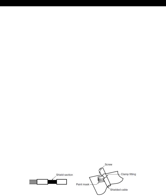
Wiring outside the cabinet must be conducted with shielded cables, and the cables must be fixed to the panel with clamps. (Strip the covering of shielded cable by a portion of clamp installation and then mask the grounding part of the panel and clamp so as not to be painted.)
9
Table for measuring element code
The following table shows a list of measuring element codes used in the manual.
Measuring element code |
Measuring element name |
A1 |
Current, 1-phase |
A2 |
Current, 2-phase |
A3 |
Current, 3-phase |
AN |
Current, N-phase |
AAVG |
Current, average |
DA1 |
Current demand, 1-phase |
DA2 |
Current demand, 2-phase |
DA3 |
Current demand, 3-phase |
DAN |
Current demand, N-phase |
DAAVG |
Current demand, average |
V12 |
Voltage, between 1-2 lines |
V23 |
Voltage, between 2-3 lines |
V31 |
Voltage, between 3-1 lines |
VAVG (L-L) |
Voltage, average, line to line |
V1N |
Voltage, 1N-phase |
V2N |
Voltage, 2N-phase |
V3N |
Voltage, 3N-phase |
VAVG (L-N) |
Voltage, average, line to neutral |
W1 |
Active power, 1-phase |
W2 |
Active power, 2-phase |
W3 |
Active power, 3-phase |
ΣW |
Active power, total |
var1 |
Reactive power, 1-phase |
var2 |
Reactive power, 2-phase |
var3 |
Reactive power, 3-phase |
Σvar |
Reactive power, total |
VA1 |
Apparent power, 1-phase |
VA2 |
Apparent power, 2-phase |
VA3 |
Apparent power, 3-phase |
ΣVA |
Apparent power, total |
PF1 |
Power factor, 1-phase |
PF2 |
Power factor, 2-phase |
PF3 |
Power factor, 3-phase |
ΣPF |
Power factor, total |
Hz |
Frequency |
Wh |
Active energy |
varh |
Reactive energy |
VAh |
Apparent energy |
DW |
Rolling demand active power |
Dvar |
Rolling demand reactive power |
DVA |
Rolling demand apparent power |
HI |
Harmonic current |
HIN |
Harmonic current, N-phase |
HV |
Harmonic voltage |
THDi |
Harmonic current total distortion ratio |
THDv |
Harmonic voltage total distortion ratio |
Aunb |
Current unbalance rate |
Vunb |
Voltage unbalance rate |
DI |
Digital input |
DO |
Digital output |
10

1. Name and Function of Each Section
Name of Each Part
<The instrument>
■The front of the unit
LCD with backlight
Operation buttons
*For details, refer to 1.3 Function of Operation Buttons.
■The back of the unit
MODBUS RTU communication terminals
T/R+: MODBUS RTU communication transmission terminal
T/R-: MODBUS RTU communication transmission terminal
SG: MODBUS RTU signal ground terminal
SLD: Shielded wire terminal (Ground resistance: 100 Ω or less)
Option cover
Remove the option cover to attach each optional plug-in module. For the terminal names of optional plug-in modules, refer to the next page.
Auxiliary power input terminals
MA, MB: Connect to an auxiliary power.
: Ground terminal (Ground resistance: 100 Ω or less)
Terminal covers
Voltage Input terminals
P1, P2, P3, PN (P1, NC, P3, P2): Circuit voltage is input.
Current Input terminals
+C1, C1: Input a circuit current. +C2, C2: Input a circuit current. +C3, C3: Input a circuit current.
11

1.Name and Function of Each Section
1.1. Name of Each Part
<The optional plugs-in module>
■The back view (Model type: ME-4210-SS96B, ME-0040C-SS96, ME-0052-SS96)
|
Input/Output terminals (ME-4210-SS96B) |
|
|
Input/Output terminals (ME-0040C-SS96) |
|
CH1+, CH1-: Analog output terminal |
|
|
DA: CC-Link communication terminal |
|
CH2+, CH2-: Analog output terminal |
|
|
DB: CC-Link communication terminal |
|
CH3+, CH3-: Analog output terminal |
|
|
DG: CC-Link communication terminal |
|
CH4+, CH4-: Analog output terminal |
|
|
SLD: Shielded wire terminal |
|
C1A/A1, C1B/COM1: Pulse/Alarm output |
|
|
FG: Ground terminal |
|
C2A/A2, C2B/COM2: Pulse/Alarm output |
|
|
(Ground resistance: 100 Ω or less) |
|
DI+, DI-: Digital input terminal |
|
|
DI1, DI2, DI3, DI4, DI COM: Digital input |
|
|
|
|
terminal |
|
|
|
||
|
|
|
|
|
Input/Output terminals (ME-0052-SS96)
DI1+, DI1-: Digital input terminal
DI2+, DI2-: Digital input terminal
DI3+, DI3-: Digital input terminal
DI4+, DI4-: Digital input terminal
DI5+, DI5-: Digital input terminal
DO1+, DO1-: Digital output terminal
DO2+, DO2-: Digital output terminal
■The side/back view ((Model type: ME-0000MT-SS96)
LED indicators
(Refer to 1.4 LED display of optional plug-in module.)
ERR. Red
10/100 Green
LINK/ACT Green
10BASE-T/100BASE-TX
 Connection connector (RJ45)
■The side/back view (Model type: ME-0000BU-SS96)

 Slot for SD memory card
LED indicators
(Refer to 1.4 LED display of optional plug-in module.)
LOG. Red
SD C. Red
BAT. Red
12
1. Name and Function of Each Section
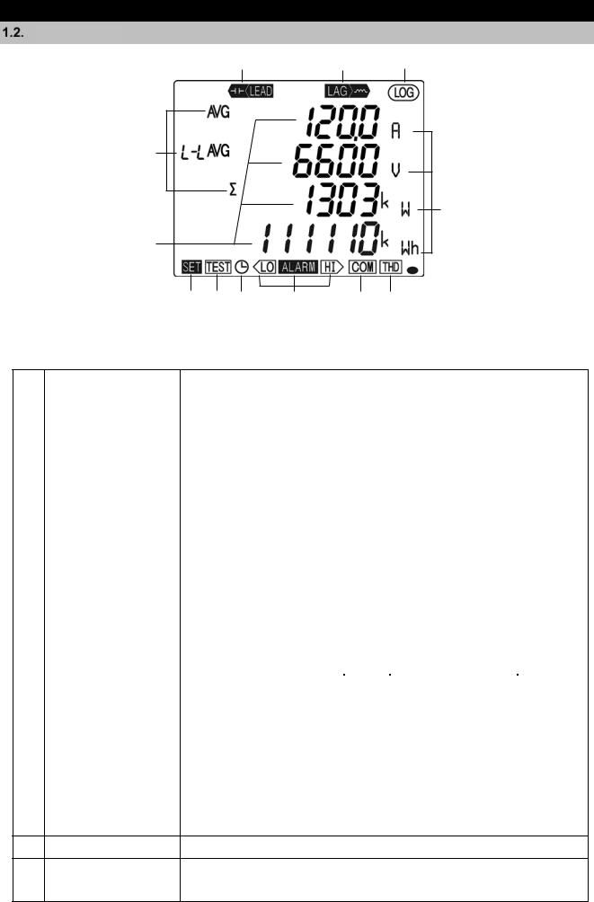
LCD Function
1 |
2 |
3 |
4
6
5
 13
13
7 |
8 |
9 |
10 |
11 |
12 |
Note: The above display is an example for explanation.
No. |
|
Name of each part |
|
|
|
Function |
|
|
|
||
|
|
|
|
|
|
|
|
|
|
|
|
1 |
|
LEAD status |
|
Light up on the reactive energy (imported lead)/ (exported lead) screen. |
|||||||
|
|
|
|
|
|
|
|
|
|
|
|
2 |
|
LAG status |
|
Light up on the reactive energy (imported lag)/ (exported lag) screen. |
|||||||
|
|
|
|
|
|
|
|
|
|
|
|
3 |
|
Built-in logging status |
|
Light up when the built-in logging function is operating |
|
|
|
||||
|
|
|
|
|
|
|
|
|
|
|
|
4 |
|
Digital element display |
|
Display measuring elements expressed in digital numbers |
|
|
|
||||
|
|
|
|
|
|
|
|
|
|
|
|
5 |
|
Digital display |
|
Display measured values in digital numbers |
|
|
|
||||
|
|
|
|
|
|
|
|
|
|
|
|
6 |
|
Unit |
|
Display the units of measured values |
|
|
|
|
|
||
|
|
|
|
|
|
|
|
|
|
|
|
7 |
|
Setup status |
|
Light up in the setting mode |
|
|
|
|
|
|
|
|
|
Blink in the setting confirmation mode |
|
|
|
|
|
||||
|
|
|
|
|
|
|
|
|
|||
8 |
|
Test mode status |
|
Light up in the test mode |
|
|
|
|
|
|
|
|
|
|
|
|
|
|
|
|
|
|
|
9 |
|
Clock status |
|
Light up when the present time is set. |
|
|
|
|
|
||
|
|
|
|
|
|
|
|
|
|
|
|
10 |
|
Upper/lower limit alarm |
|
Blink when the upper/lower limit alarm is generating |
|
|
|
||||
|
|
status |
|
|
|
|
|
|
|
|
|
|
|
|
|
|
|
|
|
|
|
|
|
|
|
|
|
|
Specification |
ON |
|
Blink |
|
OFF |
|
|
|
|
|
|
|
|
|
CC-Link version |
|
Hardware |
|
|
|
|
|
|
CC-Link communication |
Normal |
|
mismatches |
|
|
|
|
|
|
|
|
|
abnormality |
|
||||
|
|
|
|
|
|
|
|
Hardware abnormality |
|
||
|
|
Communication/ |
|
|
|
|
|
|
|
|
|
11 |
|
|
|
MODBUS RTU communication |
Normal |
|
Communication error |
|
Hardware |
|
|
|
Option |
|
|
|
such as wrong |
|
|
||||
|
|
logging status display |
|
|
MODBUS TCP communication |
|
|
address*1 |
abnormality |
|
|
|
|
|
|
|
|
|
Error occurrence such |
|
|
|
|
|
|
|
|
|
|
|
|
|
|
|
|
|
|
|
|
|
|
|
|
as setting abnormality, |
|
Hardware |
|
|
|
|
|
|
Option logging function |
Normal |
|
SD memory card error, |
|
|
|
|
|
|
|
|
|
abnormality |
|
||||
|
|
|
|
|
|
|
|
or battery voltage drop |
|
||
|
|
|
|
|
|
|
|
|
|
|
|
|
|
|
|
|
|
|
*1 |
|
|
|
|
*1. For details, refer to 6.5 Troubleshooting.
12 Harmonics |
Light up when harmonic is displayed |
13 Metering status
Blink when Imported active energy is measured *Note 1
*It appears on the imported active energy display screen only
Note 1: The blinking cycle is constant regardless of measuring input size.
13
1. Name and Function of Each Section
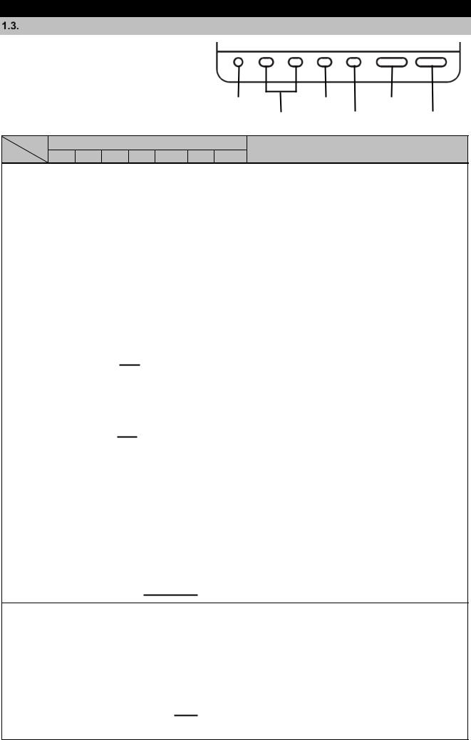
Function of Operation Buttons
The function of each operation button varies |
SET |
RESET MAX/MIN-PHASE DISPLAY |
|
depending on how to press the button. |
|||
|
|
|
SET button |
|
|
RESET button |
|
Phase button |
|
||||
|
|
|
|
|
|
|
|
||||
<Meaning of marks> |
|
+/- button |
MAX/MIN button |
DISPLAY button |
|||||||
|
|
|
|
|
|
|
|
|
|
||
○: Press, □: Press for 1 second or more, : Press for 2 seconds or more, ――:Press simultaneously
Operation |
|
|
Button name |
Function |
|
Mode |
SET |
|
RESET MAX/MIN PHASE DISPLAY |
||
|
mode Operating
confirmation Setting |
mode/ Setting |
mode |
|
|
|
|
|
|
|
|
|
|
|
|
|
|
|
|
|
|
|
|
|
|
|
|
○ |
Switch the measurement screen. |
|
||
|
|
|
|
|
|
|
|
|
|
|
|
|
|
|
|
|
|
|
|
|
|
|
|
|
|
|
|
|
|
|
|
○ |
|
|
|
|
|
|
|
|
|
|
|
|
|
|
|
|
|
○ |
Switch the measurement screen in the reverse direction. |
||||
|
|
|
|
|
|
|
|
|
|
|
|
|
|
|
|
|
|
|
|
|
|||||||
|
|
|
|
|
|
|
|
|
|
|
|
|
|
|
|
|
|
|
|
|
|
|
|
|
|
|
|
|
|
|
|
|
|
|
|
|
|
|
|
|
|
|
|
|
|
|
|
|
|
|
|
|
Switch phase display. |
|
|
Display |
|
|
|
|
|
|
|
|
|
|
|
|
|
|
|
|
|
|
|
|
○ |
|
|
Switch between the harmonic RMS value and distortion ratio. |
|||
|
|
|
|
|
|
|
|
|
|
|
|
|
|
|
|
|
|
|
|
|
|
|
|
(Available on the harmonics display screen) |
|
||
|
|
|
|
|
|
|
|
|
|
|
|
|
|
|
|
|
|
○ |
|
|
|
|
|
Enter/Exit the Max/Min value screen. |
|
||
|
|
|
|
|
|
|
|
|
|
|
|
|
|
|
|
|
|
|
|
|
|
|
|
|
|||
switching |
|
|
|
|
|
|
|
|
|
|
|
|
|
|
|
|
|
|
|
|
|
|
|
|
|
|
|
|
|
|
|
|
|
|
|
|
|
|
|
|
|
|
|
|
|
|
|
|
|
|
|
Enter the cyclic display mode of measurement screen. Refer to |
|||
|
|
|
|
○ |
○ |
|
|
|
|
|
|
|
|
|
|
|
|
Switch the harmonic degree on the harmonics display screen. |
|||||||||
|
|
|
|
|
|
|
|
|
|
|
|
|
|
|
|
|
|
|
|
|
|
|
|
5.1.3. |
|
|
|
|
|
|
|
|
|
|
|
|
|
|
|
|
|
|
|
|
|
|
|
|
|
|
|
|
Enter the cyclic display mode of phase. Refer to 5.1.3. |
||
|
|
|
|
|
|
|
|
|
|
|
|
|
|
|
|
|
|
|
|
|
|
|
|
Switch between the harmonic RMS value and distortion ratio |
|||
|
|
|
|
|
|
|
|
|
|
|
|
|
|
|
|
|
|
|
|
|
|
|
|
|
screen in cyclic mode. (Available on the harmonics display) |
||
|
|
|
|
|
|
|
|
|
|
|
|
|
|
|
|
|
|
|
|
|
|
Change the units of Wh, varh, and VAh or display the lower- |
|||||
|
|
|
|
|
|
|
|
|
|
|
|
|
|
|
|
|
|
|
digit enlarged view. Refer to 5.1.9. |
|
|||||||
|
|
|
|
|
|
|
|
|
|
|
|
|
|
|
|
|
|
|
|
|
|
Clear the Max/Min values displayed on |
|
They are available |
|||
|
|
|
|
|
|
|
|
|
|
|
|
|
|
|
|
|
|
|
|
|
the screen. |
|
|||||
|
|
|
|
|
|
|
|
|
|
|
|
|
|
|
|
|
|
|
|
|
|
on the Max/Min |
|||||
|
|
|
|
|
|
|
|
|
|
|
|
|
|
|
|
|
|
|
|
|
|
|
|
|
Clear Max/Min values for every item in |
|
|
|
|
|
|
|
|
|
|
|
|
|
|
|
|
|
|
|
|
|
|
value screen. |
|||||||
|
|
|
|
|
|
|
|
|
|
|
|
|
|
|
|
|
every screen. |
|
|||||||||
|
|
|
|
|
|
|
|
|
|
|
|
|
|
|
|
|
|
|
|
|
|
|
|
|
|
|
|
|
|
|
|
|
|
|
|
|
|
|
|
|
|
|
|
|
|
|
|
|
|
Reset Wh, varh, and VAh to zero. |
|
||||
|
|
|
|
|
|
|
|
|
|
|
|
|
|
|
|
|
|
|
All measured values are reset to zero simultaneously. |
||||||||
|
|
|
|
|
|
|
|
|
|
|
|
|
|
|
|
|
|
||||||||||
|
|
|
|
|
|
|
|
|
|
|
|
|
|
|
|
|
|
|
|
|
Reset periodic active energy to zero. |
|
|||||
clear/valueMeasured resetAlarm |
|
|
|
|
|
|
|
|
|
|
|
|
|
|
|
|
|
|
(The periodic active energy displayed on the screen only) |
||||||||
|
|
|
|
|
|
|
|
|
|
|
|
|
|
|
|
|
|
|
|
|
|
Set the rolling demand time period on the rolling demand |
|||||
|
|
|
|
|
|
|
|
|
|
|
|
|
|
|
|
|
|
screen. |
|
||||||||
|
|
|
|
|
|
|
|
|
|
|
|
|
|
|
|
|
|
|
|||||||||
|
|
|
|
|
|
|
|
|
|
|
|
|
|
|
|
|
|
Clear the rolling demand peak value on the rolling demand |
|||||||||
|
|
|
|
|
|
|
|
|
|
|
|
|
|
|
|
screen. |
|
||||||||||
|
|
|
|
|
|
|
|
|
|
|
|
|
|
|
|
|
|
|
|
|
|
Reset operating time to zero. |
|
||||
|
|
|
|
|
|
|
|
|
|
|
|
|
|
|
|
|
|
|
|
|
(The operating time displayed on the screen only) |
||||||
|
|
|
|
|
|
|
|
|
|
|
|
|
|
|
|
|
|
|
|
|
Reset CO2 equivalent to zero on the CO2 equivalent screen. |
||||||
|
|
|
|
|
|
|
|
|
|
|
|
|
|
|
|
|
|
|
|||||||||
|
|
|
|
|
|
|
|
|
|
|
|
|
|
|
|
|
|
|
|
|
|
|
|
|
|
|
|
|
|
|
|
|
|
|
|
|
|
|
|
|
|
|
○ |
|
|
|
|
|
|
Reset the alarm. |
|
They are available |
|||
|
|
|
|
|
|
|
|
|
|
|
|
|
|
|
|
|
|
|
|
|
(For the item displayed on the screen) |
|
only when set to |
||||
|
|
|
|
|
|
|
|
|
|
|
|
|
|
|
|
|
|
|
|
|
|
|
|
|
|
||
|
|
|
|
|
|
|
|
|
|
|
|
|
|
|
|
|
|
|
|
|
|
Reset all alarms at once. |
|
manual alarm |
|||
|
|
|
|
|
|
|
|
|
|
|
|
|
|
|
|
|
|
|
|
|
(For every item in every screen) |
|
cancellation. |
||||
|
|
|
|
|
|
|
|
|
|
|
|
|
|
|
○ |
|
|
|
|
|
|
Stop the backlight blinking caused by alarm. |
|||||
|
|
|
|
|
|
|
|
|
|
|
|
|
|
|
|
|
|
|
|
|
(Available only when set to backlight blinking) |
||||||
|
|
|
|
|
|
|
|
|
|
|
|
|
|
|
|
|
|
|
|
|
|
Release the latch for digital input at once on the digital input |
|||||
|
|
|
|
|
|
|
|
|
|
|
|
|
|
|
|
|
|
|
|
|
screen. |
|
|||||
Mode |
|
|
|
|
|
|
|
|
|
|
|
|
|
|
|
|
|
|
|
|
Enter the setting mode. |
|
|||||
|
|
|
|
|
|
|
|
|
|
|
|
|
|
|
|
|
|
|
|
|
|
|
|
|
|
|
|
|
|
|
|
|
|
|
|
|
|
|
|
|
|
|
|
|
|
|
|
|
|
Enter the setting confirmation mode. |
|
||||
switch |
|
|
|
|
|
|
|
|
|
|
|
|
|
|
|
|
|
|
|
|
|
|
|||||
|
|
|
|
|
|
|
|
|
|
|
|
|
|
|
|
|
|
|
|
|
|
|
|
|
|
||
|
|
|
|
|
|
|
|
|
|
|
|
|
|
|
|
|
|
|
|
|
Enter the password protection screen. |
|
|||||
|
○ |
|
|
|
|
|
|
|
|
|
|
|
|
|
|
|
|
|
|
|
|
|
Determine the settings and then shift to the next settings. |
||||
|
|
|
|
|
|
|
|
|
|
|
|
|
|
|
|
|
|
|
|
|
|
|
|
|
|
|
|
Setting |
|
|
|
|
|
|
|
|
|
|
|
|
|
|
|
|
|
|
|
|
|
|
○ |
Return to the previous setting item. |
|
||
|
|
|
|
|
|
|
|
|
|
|
|
|
|
|
|
|
|
|
|
|
|
|
|
|
|
|
|
|
|
|
|
○ |
○ |
|
|
|
|
|
|
|
|
|
|
|
|
Round up/down the setting value. |
|
||||||||
operation |
|
|
|
□ |
□ |
|
|
|
|
|
|
|
|
|
|
|
|
(Pressing for 1 second or more enables fast forward.) |
|||||||||
○ |
|
|
|
|
|
|
|
|
|
|
|
|
|
|
|
|
|
|
|
|
|
Reflect the setting change. (Available on the END screen) |
|||||
|
□ |
|
|
|
|
|
|
|
|
|
|
|
|
|
|
|
|
|
|
|
|
|
Skip the settings and return to the setting menu screen. |
||||
|
|
|
|
|
|
|
|
|
|
|
|
|
|
|
|
|
|
|
|
|
|
|
|
|
|
||
|
○ |
|
|
|
|
|
|
|
|
|
|
|
|
|
|
|
|
|
|
|
|
|
Cancel the setting change. (Available on the CANCEL screen) |
||||
|
|
|
|
|
|
|
|
|
|
|
|
|
|
|
|
|
|
|
|
|
|
|
|
|
|
|
|
Special operation |
|
|
|
|
|
|
|
|
|
|
|
|
|
|
|
|
|
|
|
|
CANCEL screen) Refer to 3.16. |
|
|||||
|
|
|
|
|
|
|
|
|
|
|
|
|
|
|
|
|
|
|
□ |
|
□ |
|
|
Restart the instrument. (Available on the CANCEL screen) |
|||
|
|
|
|
|
|
|
|
|
|
|
|
|
|
|
|
|
|
|
|
|
|
|
|
|
Initialize to the factory default settings. (Available on the |
||
|
|
|
|
|
|
|
|
|
|
|
|
|
|
|
|
|
|
|
|
|
|
|
|
|
|
|
|
14

1. Name and Function of Each Section
1.3. Function of Operation Buttons
Note: During backlight off mode, pressing any operation button first turns on the backlight. In addition, pressing any button again enables the use of the functions in the above table.
|
When you execute a function such as ‘Reset Max/Min value’ or ‘Reset Wh, varh, and |
CAUTION |
VAh to zero’, past data is deleted. If you need to keep the data, record the data before |
the reset operation. |
|
When you execute ‘Restart the instrument’, the entire measurement function |
|
|
(measurement display, communication) will stop for a few seconds. |
|
|
15

1. Name and Function of Each Section
LED Display of Optional Plug-in Module
■LED (ME-0000MT-SS96
 1. ERR.
 2. 10/100
 3. LINK/ACT
■LED (ME-0000BU-SS96
 1. LOG.
 2. SD C.
  3. BAT.
No. |
|
|
Name |
|
Function |
1 |
ERR. LED |
Indicate the communication status of |
|||
|
|
|
|
ME-0000MT-SS96. |
|
|
|
|
OFF |
Normal |
|
|
|
|
ON |
The following MODBUS TCP communication |
|
|
|
|
|
errors occur: |
|
|
|
|
|
There is an abnormality in the MODBUS TCP |
|
|
|
|
|
|
application protocol head part. |
|
|
|
|
LED becomes off when normal messages are |
|
|
|
|
|
|
received such as function code for serial. |
2 |
10/100 LED |
Indicate transmission speed |
|||
|
|
|
ON |
100 Mbps or unconnected |
|
|
|
|
OFF |
10 Mbps |
|
3 |
LINK/ACT LED |
Indicate the link status |
|||
|
|
|
ON |
The link is established. |
|
|
|
|
Blink |
Blink when sending or receiving. |
|
|
|
|
OFF |
The link is not established. |
|
|
|
|
|
|
|
No. |
|
|
Name |
|
Function |
1 |
LOG. LED |
|
Indicate the logging operation status |
||
|
|
ON |
|
Logging is operating. |
|
|
|
OFF |
|
Logging operation stops |
|
|
|
Low-speed |
|
The setting change of logging conditions has |
|
|
|
blinking |
|
been completed. |
|
|
|
(0.5 sec: on/ |
|
Blink for 5 seconds. |
|
|
|
0.5 sec: off) |
|
|
|
|
|
High-speed |
|
When the logging element pattern is LP00, |
|
|
|
blinking |
|
the setting file in the SD memory card is |
|
|
|
(0.25 sec: on/ |
|
abnormal. |
|
|
|
0.25 sec: off) |
|
Continue blinking until it turns to normal. |
|
2 |
SD |
C. LED |
|
Indicate the communication status of SD |
|
|
|
|
|
|
memory card. |
|
|
ON |
|
Communicating |
|
|
|
OFF |
|
Communication stops |
|
|
|
High-speed |
|
It is a SD memory card error |
|
|
|
blinking |
|
Check that the SD memory card is not in |
|
|
|
(0.25 sec: on/ |
|
‘write protect’ status and that there is |
|
|
|
0.25 sec: :off) |
|
available capacity. |
|
3 |
BAT. LED |
|
Indicate the battery voltage status. |
||
|
|
OFF |
|
Normal battery voltage |
|
|
|
ON |
|
Battery voltage drop |
|
16

2.Each Mode Function
The instrument has the following operation modes.
When auxiliary power is supplied, the operating mode is first displayed.
Depending on the application, switch the operation mode to use.
Mode |
Description |
Reference |
Operating |
This is a normal operation mode to display each measured value in digital |
5 Operation |
mode |
numerical number. In the operating mode, there are ‘Present value display’ that |
|
|
shows values at present and ‘Max/Min value display’ that shows the maximum |
|
|
and minimum values in the past. |
|
|
In addition, on each display screen, the cyclic display mode, which |
|
|
automatically switches the display screen every 5 seconds, is available. |
|
Setting |
This is a mode where you can change the settings for measurement and output |
3 How to |
mode |
functions. |
Set up |
|
In addition, on the CANCEL screen, which is the screen to cancel the setting |
|
|
change, the following special operations are available. |
|
|
Restart the instrument. |
|
|
Reset the settings to the factory default. |
|
Setting |
This is a mode where you can confirm the setting of each item. |
3.15 or 4 |
confirmation |
In this mode, you cannot change the setting. Therefore, it is possible to prevent |
How to Use |
mode |
from accidentally changing the setting. |
Test Mode |
(Test mode) |
The mode also provides test function available at startup of systems. |
|
|
Communication Test: Without measurement (voltage/current) input, fixed |
|
|
numerical data is returned. |
|
|
Analog output adjustment: Analog output adjustment is executed such as |
|
|
zero adjustment or span adjustment. |
|
|
Output test: Without measurement (voltage/current) input, alarm/digital |
|
|
output, analog output, or pulse output is executed. |
|
|
Support function for checking input wiring: |
|
|
When either a voltage input or current input is incorrectly wired, |
|
|
the incorrect wiring part is displayed on the screen. In addition, |
|
|
useful information is also displayed such as a current phase |
|
|
angle and voltage phase angle. |
|
■Flow of each mode
Operating mode
Present value display
Max/Min value display
Press for 2 seconds simultaneously.
SET RESET
SET |
End screen |
SET |
|
|
|
Save the |
|
When you |
settings |
|
select “End” |
|
|
in the menu |
SET
CANCEL
Cancel the screen settings
Press SET for 2 seconds
SET
When you select
“End” in the menu
Setting mode
ON
Setting confirmation mode
Blink
Test mode
17
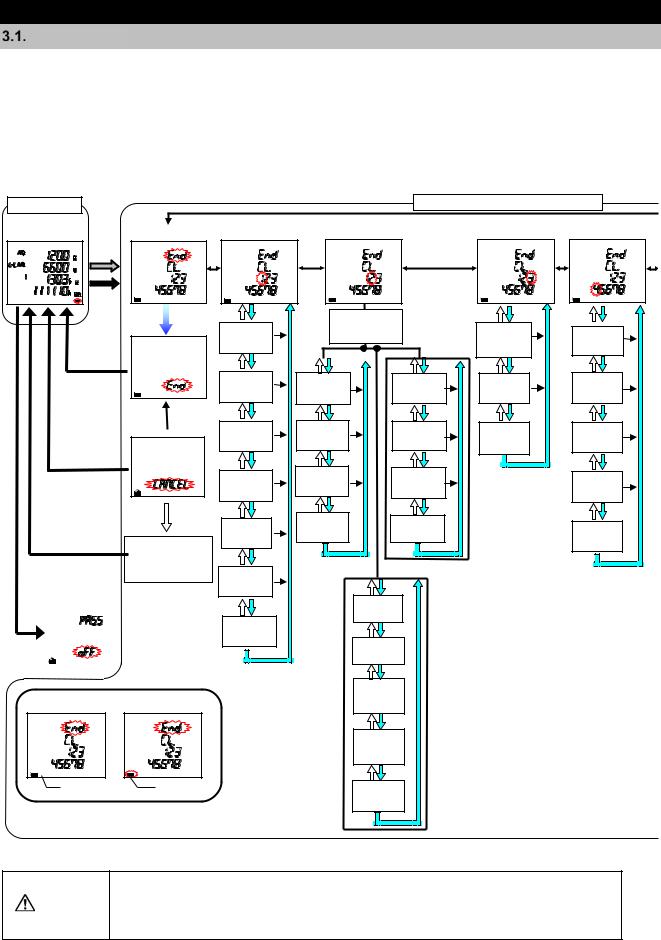
3.How to Set up
Setting Flow
For measurement, you must set settings such as phase wire system, VT/Direct voltage, and CT primary current in the setting mode.
From the operating mode, enter the setting mode and then set necessary items. Any items not set remain in the factory default.
For normal use, set up the items in the setting menu 1 only. For details on the settings, refer to 3.2. For details on the factory default settings, refer to 8.7.
Operating Mode |
|
|
Setting Menu or Setting Confirmation Mode |
|
Measurement |
Setting Menu End Setting Menu 1 |
Setting Menu 2 |
Setting Menu 3 |
Setting Menu 4 |
screen |
||||
|
*1 |
|
|
|
*2
End screen
Save the settings
CANCEL  screen
Cancel the settings
|
|
|
|
|
|
Automatic shift |
Instrument restart |
||||
|
|
|
|
|
or |
|
|
|
|
Factory default |
|
|
|
|
|
|
settings |
Password protection |
|
|
|
||
|
screen |
|
|
|
|
|
|
|
|
|
|
|
Communication |
Active/ |
|
||
Phase wire |
|
setting |
|
||
|
selection |
Reactive |
Model |
||
system |
|
||||
|
|
energy |
display |
||
|
|
|
measurement |
|
|
Display |
MODBUS |
CC-Link |
Harmonics |
Version |
|
pattern |
RTU |
Station |
display |
display |
|
|
Address |
number |
|
|
|
VT/Direct |
MODBUS |
CC-Link |
Unbalanced |
Backlight |
|
RTU |
|||||
voltage |
Baud rate |
ratio |
brightness |
||
Baud rate |
|||||
|
|
display |
|
||
|
|
|
|
||
|
MODBUS |
CC-Link |
|
Backlight |
|
CT current |
RTU |
Version |
|
||
|
Auto off/ |
||||
Parity |
setting |
|
|||
|
|
ON |
|||
|
|
|
|
||
|
MODBUS |
CC-Link |
|
|
|
|
RTU |
|
Display |
||
Frequency |
Reset |
|
|||
Stop bit |
|
Update |
|||
|
|
|
|
time |
|
Rolling |
|
<When ME-0040C-SS96 is installed> |
|
||
|
|
|
|
||
demand |
|
|
|
|
|
time period |
|
MODBUS |
|
|
|
|
|
|
|
||
|
|
TCP |
|
|
|
Demand |
|
IP address |
|
|
|
current |
|
|
|
|
|
time period |
|
MODBUS |
|
|
|
|
|
TCP |
|
|
|
|
|
Subnet mask |
|
|
|
|
|
|
MODBUS |
Example of |
Example of Setting |
|
TCP |
|
Default |
||
Setting Mode |
Confirmation Mode |
|
gateway use |
|
|
|
MODBUS |
|
|
|
TCP |
|
|
|
Default |
|
|
|
gateway |
|
|
<When ME-0000MT-SS96 is |
|
ON |
Blink |
installed> |
MODBUS |
|
|
|
TCP |
|
|
|
Reset |
*1: If password protection is enabled, password input is necessary to enter the setting mode from the operating mode.
*2: In the setting confirmation mode, the screen returns to the operating mode.
*3: This is not displayed in the setting mode.
When you change a setting, the related setting items and measured data will be
CAUTION initialized. Therefore, check that beforehand.
For details on the initialization, refer to 3.16 Initialization of Related Items by
Changing a Setting.
18

3.How to Set up
3.1. Setting Flow
<Setting Procedure> |
|
buttons simultaneously for 2 seconds to enter the setting mode. |
||
Press the |
SET |
and |
RESET |
|
Select the setting menu number with the or button. |
||||
Press the |
SET |
button to determine the setting menu number. |
||
Set each setting item. (Refer to 3.2 to 3.14.)
After completing all the settings, select End in the setting menu and then press the SET button.When the End screen appears, press the SET button again.
Setting menu or Setting Confirmation Mode
*3
Setting Menu 5 |
|
Setting Menu 6 |
|
Setting Menu 7 |
|
Setting Menu 8 |
|
Setting Confirmation |
|
|
|
|
|
Menu 9 |
|||||
|
|
|
|
|
|
|
|
|
|
|
|
Option |
|
Operating |
|
|
|
*3 |
Upper/Lower |
|
selection |
Periodic |
|
|
|
Test Mode |
|
limit alarm |
|
|
active energy |
time |
|
|
|
|
item |
|
|
Display |
Display |
|
|
|
|
|
|
|
|
|
|
|
||
Upper/Lower |
Built-in |
|
Periodic |
Operating |
|
|
|
|
|
time |
|
|
|
|
|||
limit alarm |
logging |
Logging ID |
active energy |
|
|
|
|
|
value |
Data clear |
|
Switching |
Count target |
|
|
|
|
|
|
|
|
|
|
|||
Alarm |
Built-in |
Logging |
Rolling |
Operating |
|
|
|
|
logging |
demand |
time |
|
|
|
|
||
delay time |
Use |
Data clear |
Display |
Threshold |
|
|
|
|
|
|
|
|
|
||||
Alarm reset |
Built-in |
Logging |
Rolling |
IEC mode |
|
|
|
|
logging |
Item |
demand |
|
|
|
|||
method |
settings |
|
|
|
|
|||
|
Item pattern |
pattern |
Time period |
|
|
|
|
|
Backlight |
Built-in |
Detailed data |
Contact |
CO2 |
|
|
|
|
blinking |
logging |
Logging |
input/output |
Equivalent |
|
|
|
|
for alarm |
Period |
period |
Display |
display |
|
|
|
|
Motor starting |
|
<When ME-0000BU-SS96 |
Contact |
CO2 |
|
|
|
|
current |
|
is installed> |
input |
Conversion |
|
|
|
|
delay time |
|
Reset method |
rate |
|
|
|
|
|
Analog |
|
|
|
|
|
|||
|
|
|
|
|
|
|
|
|
Pulse/Alarm |
Output 1 |
|
|
|
|
|
|
|
|
<When ME-0052-SS96 is installed> |
|
|
|
|
|||
output |
|
|
|
|
|
|||
|
Mark |
|
|
|
|
|
|
|
function |
Analog |
Action |
|
|
Button operation |
|||
|
Enter the setting mode from the operating mode |
|
|
|
|
Press for 2 seconds |
||
|
Output 2 |
|
|
RESET |
||||
|
|
|
|
SET |
simultaneously |
|||
Pulse |
|
Enter the setting confirmation mode from the operating mode |
|
SET |
|
Press for 2 seconds |
||
output |
Analog |
Select the menu number to set up or select End |
|
or |
|
Press several times |
||
|
Enter the setting screen. Shift to the next setting item |
|
|
SET |
|
Press |
||
|
Output 3 |
|
|
|
||||
|
Return to the previous setting item |
|
|
|
|
Press |
||
|
|
|
DISPLAY |
|
||||
<When ME-4210-SS96B |
|
Omitted Select a set value. |
|
|
|
or |
|
Press several times. |
is installed> |
Analog |
Shift to the End screen |
|
|
|
SET |
|
Press |
|
|
|
|
|
||||
|
Output 4 |
Save the settings and then return to the operating mode |
|
SET |
|
Press |
||
|
|
Select CANCEL |
|
|
|
or |
|
Press |
|
|
Cancel the settings. |
|
|
|
SET |
|
Press |
|
Output |
Skip the current settings during setup |
|
|
SET |
|
Press for 1 second |
|
|
limit |
|
|
|
|
|||
|
Reset the settings to the factory default. |
|
RESET |
+ |
PHASE |
Press for 2 seconds |
||
<When ME-4210-SS96B |
|
|||||||
Enter the password protection screen from the operating mode |
|
+ |
|
Press for 2 seconds |
||||
is installed> |
|
RESET |
PHASE |
|||||
■Basic operation for settings
The following table shows a list of basic operations for settings.
|
Function |
|
|
|
Operation |
|
Note |
||
|
Select a setting |
|
Press |
|
or |
|
button |
Fast-forward by pressing for 1 second or more |
|
|
|
|
|
|
|
|
|
|
|
|
Determine a setting |
|
Press |
SET |
button |
|
|
When the setting is determined, the screen |
|
|
|
|
|
switches to the next setting item. |
|||||
|
|
|
|
|
|
|
|
|
|
|
Return to the previous |
|
Press |
DISPLAY |
button |
|
|
||
|
setting item |
|
|
The setting before return is enabled. |
|||||
|
|
|
|
|
|
|
|
||
|
Return to the setting menu |
|
Press |
SET |
button for 1 second |
|
|||
|
|
|
|
||||||
|
during setup |
|
|
|
|||||
|
|
|
|
|
|
|
|
|
|
|
|
|
|
|
|
|
19 |
|
|
3.How to Set up
Setting Menu 1: Basic Setup (Settings for Phase Wire System, Display Pattern,
VT/Direct Voltage, and CT Primary Current)
You will set the phase wire system, display pattern, VT/Direct voltage, CT primary current, and demand time period.
In the operating mode, press SET and RESET simultaneously for 2 seconds or more to enter the following operation.
Select 1 in the setting menu number.
*Refer to the right figure.
Setting Menu
DISPLAY SET
Phase wire system 
Set the phase wire system
according to the measurement target circuit.
3P4: |
|
3-phase 4-wire |
Note: The underlined |
|
shows the |
||
3P3. |
2CT: |
3-phase 3-wire 2CT |
default setting. |
3P3. 3CT: |
3-phase 3-wire 3CT |
(The same as below) |
|
1P3. |
1N2: 1-phase 3-wire 1N2 display |
||
1P3. |
1N3: 1-phase 3-wire 1N3 display |
||
1P2: |
|
1-phase 2-wire |
|
|
Set the display pattern. |
<When 1-phase 2-wire system is |
||
|
P01 |
P02 |
P00 |
|
DISPLAY SET |
|
|
|
set at Phase wire system.> |
|
|
|
|
P02 is not selectable. |
|
The following table shows measuring elements displayed on |
|||
|
each display pattern. The measuring elements displayed on P01 |
|||
|
and P02 are the same. For P01, four elements are displayed in |
|||
|
one screen. For P02, each phase is displayed in one screen. For |
|||
|
details, refer to 6.1. |
|
|
|
|
P00 is a special display pattern to freely set display items. For |
|||
|
details on the settings, refer to 3.18. |
|||
Display Pattern |
○Displayable only by this setting |
|||
|
Other additional settings are necessary to display. |
|||
|
□Select ‘P00’ and set up the display order and position. |
|||
|
|
1) When set to 3-phase 4-wire system |
|
|
|
PatternDisplay |
Additional Screen *Note |
|
|
Equivalent TimeOperating statusInput/outputDigital RateUnbalance Current/VoltageHarmonic DemandRolling EnergyActivePeriodic EnergyApparent (Special)EnergyReactive (Exported)EnergyActive (Imported)EnergyActive EnergyApparent lag)(ImportedEnergyReactive (ExportedEnergy) Active (Imported)EnergyActive Frequency PowerApparent PowerReactive FactorPower PowerActive Voltage demandCurrent phaseNdemandCurrent Current phaseNCurrent |
|
|
|
|
CO |
|
|
|
2 |
DISPLAY |
SET |
|
|
|
|
P01 |
○ ○ ○ ○ ○ ○ ○ ○ ○ ○ ○ ○ ○ ○ ○ ○ ○ ○ |
|
|
P02 |
○ ○ ○ ○ ○ ○ ○ ○ ○ ○ ○ ○ ○ ○ ○ ○ ○ ○ |
|
|
P00 |
□ □ □ □ □ □ □ □ □ □ □ □ □ □ |
Continued to the next page.
20

3.How to Set up
3.2Setting Menu 1: Basic Setup (Settings for Phase Wire System, Display Pattern, VT/Direct Voltage, and CT Primary Current)
Continued from the previous page.
2 When set to other than 3-phase 4-wire system *For 1-phase 2-wire system, P02 is not selectable.
|
Additional Screen *Note |
|
CO |
|
2 |
Pattern Display |
Equivalent TimeOperating Status Input/outputDigital RateUnbalance Current/VoltageHarmonic DemandRolling Energy ActivePeriodic EnergyApparent (Special) EnergyReactive (Imported) EnergyActive (Imported) EnergyActive ApparentEnergy lag) (Imported ReactiveEnergy (ExportedEnergyActive) (Imported)EnergyActive Frequency ApparentPower ReactivePower FactorPower PowerActive Voltage demandCurrent Current |
P01 |
○ ○ ○ ○ ○ ○ ○ ○ ○ ○ ○ ○ ○ ○ ○ ○ |
P02 |
○ ○ ○ ○ ○ ○ ○ ○ ○ ○ ○ ○ ○ ○ ○ ○ |
P00 |
□ □ □ □ □ □ □ □ □ □ □ □ |
Note: The following settings are necessary to display the elements of the additional screens.
|
Measuring element |
|
|
Setting item |
|
Reference |
|
|
of the additional screen |
|
|
|
|
||
|
Active energy (Exported), |
|
Setting menu 3 Active/Reactive energy |
3.6 |
|
||
|
Reactive energy (Special)* |
|
measurement |
|
|
||
|
|
|
|
|
|
||
|
Harmonic current, Harmonic voltage |
|
Setting menu 3 Harmonics display |
3.6 |
|
||
DISPLAY SET |
Unbalance rate |
|
Setting menu 3 Unbalance rate display |
3.6 |
|
||
|
Periodic active energy |
|
Setting menu 7 Periodic active energy display |
3.12 |
|
||
|
Rolling demand |
|
Setting menu 7 Rolling demand display |
3.12 |
|
||
|
Digital input/output status |
|
Setting menu 7 |
Digital input/output display |
3.12 |
|
|
|
Operating time |
|
Setting menu 8 |
Operating time display |
3.13 |
|
|
|
CO2 equivalent |
|
Setting menu 8 |
CO2 equivalent display |
3.13 |
|
|
*To display the additional screens of active/reactive/apparent energy of P00, you must set each item as display element.
VT/Direct voltage
DISPLAY SET
Set the settings for VT.
For direct measurement (without VT) Select no, and then press SET . Follow the settings of (1).
For measurement with VT Select yES and then press SET . Follow the settings of (2).
1. When set to 3-phase 4-wire system no yES
2. When set to 3-phase 3-wire/1-phase 2-wire system yES 
 no
no
Note. VT is Voltage Transformer. When you set 1-phase 3-wire at phase wire system, direct measurement input only is available. This setting will be skipped.
(1) For direct measurement input (without VT)
(a) When set to 3-phase 4-wire system (Phase voltage/Line voltage)
 63.5/110 V
 100/173 V
 110/190 V
 220/380 V
 230/400 V
 240/415 V
 277/480 V
 254/440 V
(b)When set to 3-phase 3-wire system (2CT, 3CT) /1-phase 2-wire system (Line voltage)

 110 V
110 V
 220 V
220 V
 440 V
440 V 

(c)When set to 1-phase 3-wire system (1N2, 1N3) (Phase voltage/Line voltage)

 110/220 V
 220/440 V

21

3.How to Set up
3.2Setting Menu 1: Basic Setup (Settings for Phase Wire System, Display Pattern, VT/Direct Voltage, and CT Primary Current)
DISPLAY SET
CT current
DISPLAY SET
Frequency
Continued form the previous page.
(2) For measurement with VT
<Secondary voltage setting>
(a) When set to 3-phase 4-wire system (Phase voltage) 
 63.5 V
 100 V
100 V
 110 V
110 V
 115 V
115 V
 120 V
120 V

(b)When set to 3-phase 3-wire (2CT, 3CT) /1-phase 2-wire system (Line voltage)
 100 V
100 V
 110 V
110 V
 220 V
220 V 

<Primary voltage setting> The factory default settings:
For 3-phase 4-wire system 200 V (Phase voltage)For 3-phse 3-wire/1-phase 2-wire system 10000 V
(Line voltage)
From the upper digit, set the blinking digit with or .
By pressing SET , move the setting item, blinking one, to a lower digit.
By pressing DISPLAY , move the setting item, blinking one, to an upper digit.The setting ranges from 60 V to 750000 V. The setting unit is V.
*If you set out of range, the error message (E05) will appear.
If the error message appears, press SET and then review the setting to set it again.
By pressing SET at the lowest digit, shift to the next setting item.
Set the settings for CT.
You will set the primary and secondary current of CT.
<Secondary current setting>
1 A 
 5 A
5 A
Note: CT is Current Transformer.
<Primary current setting>
The factory default setting: 5.0 A
From the upper digit, set the blinking digit with orBy pressing SET , move the setting item, blinking one, to a
lower digit.By pressing DISPLAY move the setting item, blinking one, to
an upper digit.The setting ranges from 1.0 A to 30000.0 A.
The setting unit is A.
*If you set out of range, the error message (E05) will appear. If the error message appears, press SET and then review the setting to set it again.
By pressing SET at the lowest digit, shift to the next setting item.
Set the frequency.
50 Hz 
 60 Hz
60 Hz
22

3.How to Set up
3.2Setting Menu 1: Basic Setup (Settings for Phase Wire System, Display Pattern, VT/Direct Voltage, and CT Primary Current)
DISPLAY SET
Rolling demand time period
DISPLAY SET
Current demand time period
SET
Setting Menu
Set the interval time period for rolling demand. *For details on the rolling demand, refer to 5.2.7.
(1) |
Interval time period |
|
|
|
|
|
Setting range |
Setting step |
|
|
|
|
|
|
|||
|
|
|
|||
|
1 to 15 to 60 min |
1 min |
|
|
|
(2) |
Subinterval time period |
|
|
|
|
|
|
|
|
||
|
Setting range |
Setting step |
|
|
|
|
1 to 60 min |
1 min |
|
|
|
|
|
|
|
|
|
If you set the interval time period to a value that is not divisible by the subinterval time period, the error (E05) will appear.
If the error appears, press SET and review the setting to set it again.
Even when you set the rolling demand to ‘oFF (Not display)’, this screen appears. If rolling demand is not necessary, just press SET .
Set the current demand time period. |
|
|||
For details on the current demand time period, refer to 5.1.13. |
||||
0 s |
40 s |
3 min |
7 min |
15 min |
10 s |
50 s |
4 min |
8 min |
20 min |
20 s |
1 min |
5 min |
9 min |
25 min |
30 s |
2 min |
6 min |
10 min |
30 min |
Note: Even when you set a display pattern that does not display current demand, this screen appears. If current demand is not necessary, just press SET .
According to 3.1 Setting Flow,
complete the settings or shift to other setting menu.
If you set the settings only in the setting menu 1 to use, move to 5 Operation.
If you use an additional function, set it in the setting menu 2 to 8.
|
If you change a setting in the setting menu 1, the maximum and minimum values of the |
Note |
related measuring elements will be reset. However, active/reactive/apparent energy value |
will not be reset. |
|
|
For details, refer to 3.16 Initialization of Related Items by Changing a Setting. |
|
|
23

3.How to Set up
Setting Menu 2: Communication Settings (MODBUS RTU Communication Settings)
<The installation conditions for optional plug-in module> No installation
In the operating mode, press SET and RESET simultaneously for 2 seconds or more to enter the following operation.
Select 2 in the setting menu number. *Refer to the right figure.
Setting Menu
DISPLAY SET |
Select option (CC-Link or MODBUS TCP communication) |
||
|
or MODBUS RTU communication. |
||
|
CC or tcP |
rtu |
|
|
(Option) |
(MODBUS RTU communication) |
|
Communication |
The explanation here is about the MODBUS RTU communication |
||
setting selection (1) |
settings. |
|
|
For the CC-Link communication settings, refer to 3.4. |
|||
|
|||
|
For the MODBUS TCP communication settings, refer to 3.5. |
||
DISPLAY SET |
Note: When ME-0040C-SS96 or ME-0000MT-SS96 of optional plug-in module |
||
|
is not installed, this setting is skipped. |
||
|
Set the address of MODBUS RTU communication. |
||
MODBUS RTU |
Settable address: 1 to 255 |
|
|
Address |
|
||
|
|
||
DISPLAY SET
Set the baud rate of MODBUS RTU communication.
|
|
|
|
|
|
|
|
|
|
|
|
|
2400 bps |
|
|
|
|
MODBUS RTU |
|
|
||||||
|
|
|
4800 bps |
|
|
|
||
Baud rate |
|
|
|
|
|
|
||
|
|
|
9600 bps |
|
|
|
||
|
|
|
|
|
|
|
||
|
|
|
|
19.2 kbps |
|
|
|
|
|
|
|
|
|
|
|
||
DISPLAY SET |
|
|
|
38.4 kbps |
|
|
|
|
|
|
|
|
|
|
|||
|
|
|
|
|
|
|
|
|
|
|
|
|
|
|
|
|
|
|
|
|
|
|
|
|
|
|
MODBUS RTU
Parity
DISPLAY SET
MODBUS RTU Stop bit
SET
Setting Menu
Set the parity of MODBUS RTU communication.
non odd
even (EVEn)
Set the stop bit of MODBUS RTU communication.
Stop bit 1 |
|
Stop bit 2 |
|
|
|
||
|
|
|
|
|
|
|
|
According to 3.1 Setting Flow,
complete the settings or shift to other setting menu.
In addition, if you need to set the settings for CC-Link or MODBUS TCP communication, select the setting menu 2 again
and then select ‘CC’ or ‘Mb.rtu’ at Communication setting selection.
24
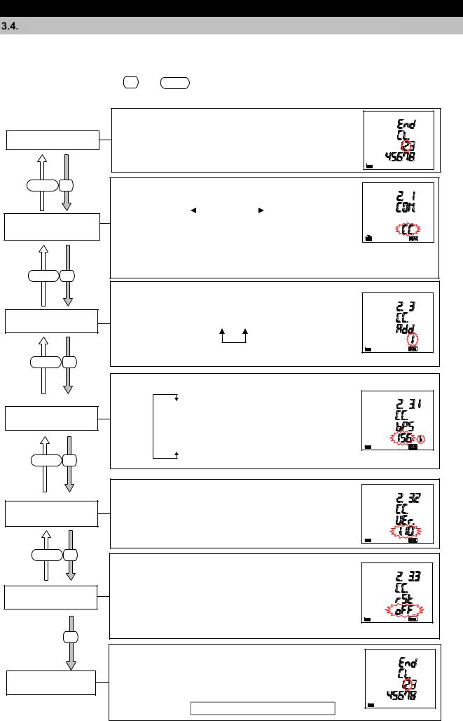
3.How to Set up
Setting Menu 2: Communication Settings (CC-Link Communication Settings)
<The installation conditions for optional plug-in module> ME-0040C-SS96 installation
In the operating mode, press SET and RESET simultaneously for 2 seconds or more to enter the following operation.
Setting Menu
DISPLAY SET
Communication setting selection
DISPLAY SET
CC-Link
Station number
DISPLAY SET
CC-Link
Baud rate
DISPLAY SET
CC-Link Version setting
DISPLAY SET
Communication reset
SET
Setting Menu
Select 2 in the setting menu number. *Refer to the right figure.
Select CC-Link communication or MODBUS RTU communication.
CC |
|
|
rtu |
|
|
|
|
||
(CC-Link communication) |
(MODBUS RTU communication) |
|
||
|
|
|
|
|
|
|
|
|
|
The explanation here is about CC-Link communication settings. For the MODBUS RTU communication settings, refer to 3.3.
Set the station number of CC-Link communication.
Settable station number: 1 to 64
Set the baud rate of CC-Link communication.
156 kbps
625 kbps
2.5 Mbps
5 Mbps
10 Mbps
Set the version of CC-Link communication.
Version 1.10 
 Version 2.00
If you have changed a setting related to CC-Link communication, set to ‘on.’
*If you do not set to ‘on’, the changed setting will not be enabled.
oFF 
 on
on
According to 3.1 Setting Flow,
complete the settings or shift to other setting menu.
In addition, if you need to set the settings for MODBUS RTU communication, select the setting menu 2 again and
select ‘Mb. rtu’ at Communication setting selection.
25
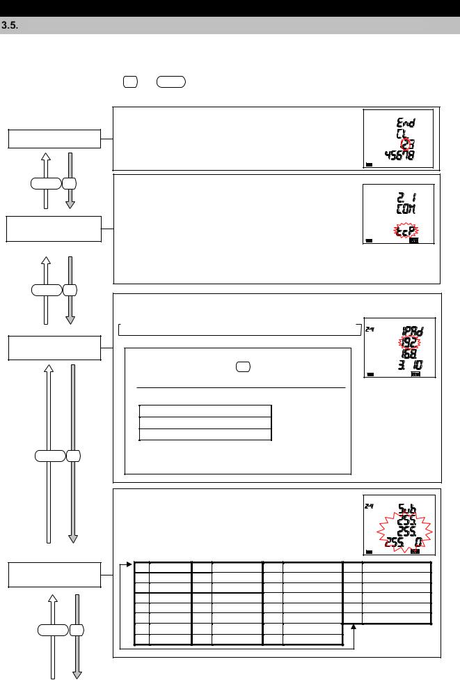
3.How to Set up
Setting Menu 2: Communication Settings (MODBUS TCP Communication Settings)
<The installation conditions for optional plug-in module> ME-0000MT-SS96 installation
In the operating mode, press SET and RESET simultaneously for 2 seconds or more to enter the following operation.
Setting Menu
DISPLAY SET
Communication setting selection
DISPLAY SET
MODBUS TCP
IP address
DISPLAY SET
MODBUS TCP Subnet mask
DISPLAY SET
Select 2 in the setting menu number. *Refer to the right figure.
Select MODBUS TCP communication or MODBUS RTU communication.
tcP 
 rtu
rtu
(MODBUSTCP (MODBUS RTU communication) communication)
The explanation here is about MODBUS TCP communication settings. For the MODBUS RTU communication settings, refer to 3.3.
Set the IP address of MODBUS TCP communication.
 000.000.000.000 to 192.168.3.10 to 255.255.255.255
*If you set an invalid address, the error (E05) will appear.
If the error appears, press SET and review the setting to set it again.
[The setting range of IP address] 1.0.0.0 to 126.255.255.255
128.0.0.0 to 191.255.255.255
192.0.0.0 to 223.255.255.255
However, the following IP addresses are impossible to set:0.0.0.0
xxx.xxx.xxx.255 (xxx is any number.)
Set the subnet mask of MOCBUS TCP communication.
Select a subnet mask setting from the following 30 types in the table.
(1) |
128.0.0.0 |
(9) |
255.128.0.0 |
(17) |
255.255.128.0 |
(25) |
255.255.255.128 |
(2) |
192.0.0.0 |
(10) |
255.192.0.0 |
(18) |
255.255.192.0 |
(26) |
255.255.255.192 |
(3) |
224.0.0.0 |
(11) |
255.224.0.0 |
(19) |
255.255.224.0 |
(27) |
255.255.255.224 |
(4) |
240.0.0.0 |
(12) |
255.240.0.0 |
(20) |
255.255.240.0 |
(28) |
255.255.255.240 |
(5) |
248.0.0.0 |
(13) |
255.248.0.0 |
(21) |
255.255.248.0 |
(29) |
255.255.255.248 |
(6) |
252.0.0.0 |
(14) |
255.252.0.0 |
(22) |
255.255.252.0 |
(30) |
255.255.255.252 |
(7) |
254.0.0.0 |
(15) |
255.254.0.0 |
(23) |
255.255.254.0 |
|
|
(8) |
255.0.0.0 |
(16) |
255.255.0.0 |
(24) |
255.255.255.0 |
|
|
26

3.How to Set up
3.5. Setting Menu 2: Communication Settings (MODBUS TCP Communication Settings)
MODBUS TCP Default gateway use
DISPLAY SET
MODBUS TCP Default gateway
DISPLAY SET
Communication reset
SET
Setting Menu
Set whether default gateway exists.
If there is default gateway on the Ethernet, set to ‘on’ to communicate with other network.
oFF 
 on
on
Set the address of default gateway.
If you set  MODBUS TCP Default gateway use
 to “oFF”, this screen will not be displayed.
 000.000.000.000 to 127.0.0.1 to 255.255.255.255
*If you set an invalid address, the error (E05) will appear.
If the error appears, press SET and review the setting to set it again.
The following default gateway addresses are impossible to set:0.0.0.0
xxx.xxx.xxx.255 (xxx is any number.)
If you have changed a setting related to MODBUS TCP communication, set to ‘on.’
*If you do not set to “on”, the changed setting will not be enabled.
oFF 
 on
on
According to 3.1 Setting Flow,
complete the settings or shift to other setting menu.
In addition, if you need to set the settings for MODBUS RTU communication, select the setting menu 2 again and
select ‘Mb. rtu’ at Communication setting selection.
27

3.How to Set up
Setting Menu 3: Display Settings (Settings for Active/Reactive Energy and Harmonic
Measurement)
This section describes how to set the special measurement of active/reactive energy and harmonic display.
In the operating mode, press SET and RESET simultaneously for 2 seconds or more to enter the following operation.
Setting Menu
DISPLAY SET
Active/Reactive energy measurement
DISPLAY SET
Harmonics display
Select 3 in the setting menu number. *Refer to the right figure.
Set the display combination of active energy and reactive energy
(imported/exported, lag/lead) and the measurement method of reactive energy.
|
|
|
|
|
|
Active energy |
|
|
Reactive energy |
|
Reactive |
|
|||||||
|
Combination |
|
|
|
(Wh) |
|
|
|
(varh) |
|
|
energy |
|
||||||
|
(Setting) |
|
|
Imported |
|
|
Exported |
|
|
Imported |
Exported |
|
measurement |
|
|||||
|
|
|
|
|
|
|
|
|
|
lag |
lead |
lag |
lead |
|
method |
|
|||
|
|
|
|
|
|
|
|
|
|
||||||||||
|
|
|
|
|
○ |
|
|
|
|
|
|
○ |
|
|
|
|
2 quadrant |
||
|
|
|
|
|
|
|
|
|
|
|
|
|
|
|
|
measurement |
|||
|
|
|
|
○ |
|
|
|
|
|
|
○ |
○ |
|
|
|
||||
|
|
|
|
|
|
|
|
|
|
|
|
|
|
|
|||||
|
|
|
○ |
|
|
|
○ |
|
○ |
|
○ |
|
|
4 quadrant |
|||||
|
|
|
○ |
|
|
|
○ |
|
○ |
○ |
○ |
○ |
|
measurement |
|||||
Note: For details on how to measure reactive energy, refer to 5.1.11.
Combination , They are suitable for measuring systems without a private power generator or measuring reactive power of capacitor load where power factor is around zero generally.
Combination , They are suitable for measuring systems with a private power generator.
<Display exapmles>
Combination |
Combination |
Combination |
Combination |
Imported |
Exported |
varh (lead) |
varh (lag) |
When ‘Wh’ or ‘varh’ is selected in the display pattern of P00, it is displayed.
Set the harmonic display.
on |
|
|
oFF |
|
|
|
|
||
(Display) |
(Not display) |
|
||
|
|
|
|
|
|
|
|
|
|
When you set to ‘on (Display)’, harmonic measured values are displayed on the additional screen of display pattern.
28
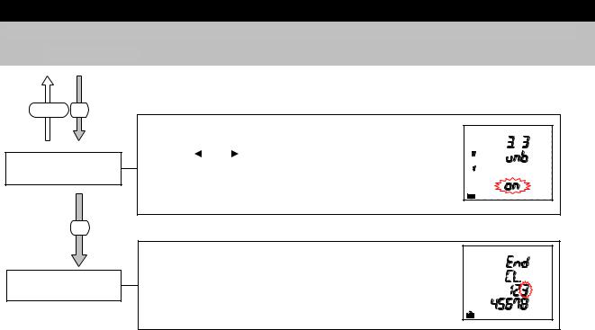
3.How to Set up
3.6Setting Menu 3: Display Settings (Settings for Active/Reactive Energy and Harmonic Measurement)
DISPLAY SET
Unbalance rate display
Set whether to display the unbalance rate.
on |
|
|
oFF |
Note: For 1-phase 2-wire system, |
|
|
|||
(Display) |
(Not display) |
this setting is skipped. |
||
When you set to ‘on (Display)’, the voltage/current unbalance rate can be displayed on the additional screen of display pattern.
SET
According to 3.1 Setting Flow,
complete the settings or shift to other setting menu.
Setting Menu
|
|
|
|
|
|
|
|
|
|
|
|
|
|
|
|
|
|
|
|
|
|
|
|
Even when you select a display pattern that does not display active/reactive power or |
||||||||
|
|
active/reactive energy, the setting items of |
Active/Reactive energy |
measurement |
are |
|||||
Note |
|
displayed because the symbol can be displayed as appropriate for 2 |
quadrant/4 quadrant |
|
||||||
|
|
measurement of reactive power/power factor according to the settings of |
|
Active/Reactive |
|
|||||
|
|
energy measurement. |
|
|
|
|
|
|
|
|
|
|
|
|
|
|
|
|
|
|
|
29
Loading...