


|
|
|
|
|
|
|
|
|
|
|
|
|
|
|
|
|
|
|
|
|
|
|
|
|
|
|
|
|
|
|
|
|
|
|
|
|
|
|
|
|
|
|
|
|
|
|
|
|
|
|
|
|
|
|
|
|
|
|
|
|
|
|
|
|
|
|
|
|
|
|
|
|
|
|
|
|
|
|
|
|
|
|
|
|
|
|
|
|
|
|
|
|
|
|
|
|
|
|
|
|
|
|
|
|
|
|
|
|
|
|
|
|
|
|
|
|
|
|
|
|
|
|
|
|
|
|
Revision A: |
|
|
|
|
|
|
|
|
|
|
|
|
|
|
|
|
|
|
|
|
|
|
|
|
|
|
|
|
|
|
|
|
|
|
|
|
|
|
|
|
|
|
|
|
|
|
|
|
|
|
|
|
|
|
|
|
|
|
|
|
|
|
|
|
|
|
|
|
|
|
|
|
|
|
|
|
|
|
|
|
|
|
|
|
|
|
|
|
|
|
|
|
|
|
|
|
|
|
|
|
|
|
|
|
|
|
|
|
|
|
|
|
|
|
|
|
|
|
|
|
|
|
|
|
|
|
|
● RoHS PARTS LIST has been added. |
|
|
|
|
|
|
|
|
|
|
|
|
|
|
|
|
|
|
|
|
|
|
|
|
|
|
|
|
|
|
|
|
FLOOR AND CEILING TYPE AIR CONDITIONERS |
|
||||||||||||||||||||||||||||||
Please void OB380. |
|||||||||||||||||||||||||||||||
INDOOR UNIT
SERVICE MANUAL
No. OB380
REVISED EDITION-A
Wireless type
Models
MCFH-GA35VB - E1
MCFH-GA50VB - E1
MCFH-GA60VB - E1
Outdoor unit service manual
MUCFH-GA•VB Series (OB381)
MXZ-A•WV Series (OB319)
CONTENTS
(When installed on the floor)
(When installed on the ceiling)
1.TECHNICAL CHANGES ··············
2.PART NAMES AND FUNCTIONS··········
3.SPECIFICATION··················
4.NOISE CRITERIA CURVES ·············
5.OUTLINES AND DIMENSIONS ···········
6.WIRING DIAGRAM ················
7.REFRIGERANT SYSTEM DIAGRAM ········
8.SERVICE FUNCTIONS ···············
9.TROUBLESHOOTING···············
10.DISASSEMBLY INSTRUCTIONS··········
11.PARTS LIST····················
12.RoHS PARTS LIST················
13.OPTIONAL PARTS················
NOTE:
This service manual describes technical data of the indoor units. RoHS compliant products have <G> mark on the spec name plate.
For servicing of RoHS compliant products, refer to the RoHS PARTS LIST (RoHS compliant).
Revision A :
• RoHS PARTS LIST has been added.
1 
 TECHNICAL CHANGES
MCFH-A12WV- E1 MCFH-GA35VB- E1
1. Model name has been changed.
MCFH-A18WV- E1 MCFH-GA50VB- E1
1. Model name has been changed.
MCFH-A24WV- E1 MCFH-GA60VB- E1
1. Model name has been changed.
2 
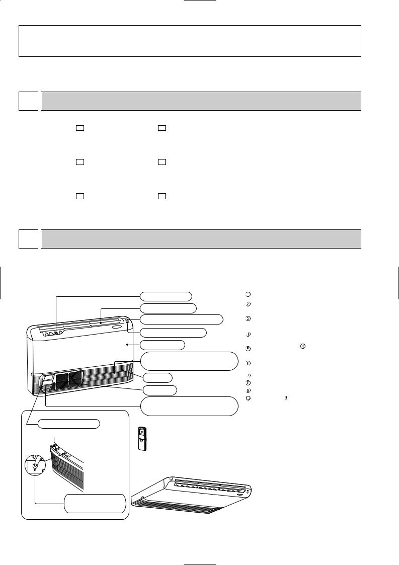
 PART NAMES AND FUNCTIONS
MCFH-GA35VB MCFH-GA50VB MCFH-GA60VB
(When installed on the floor)
Vertical vanes
Horizontal vane
Operation indicator lamp
Receiving section
Front panel
Air cleaning filter
(white bellows type)(option)
Air inlet
Air filter
Deodorizing filter
(gray sponge type)(option)
Operation section
(When the air inlet grille is opened.)


 Remote controller
(When installed on the ceiling)
Emergency operation switch
ACCESSORIES
|
Item |
Q'ty |
|
Installation plate |
2 |
|
Unit fixing screw |
2 |
|
5 o 12mm |
|
|
|
|
|
Wireless remote |
1 |
|
controller |
|
|
|
|
|
Remote controller |
1 |
|
mounting hardware |
|
|
|
|
|
Fixing screw for |
2 |
|
3.5 o 16mm (Black) |
|
|
|
|
|
Battery (AAA) for |
2 |
|
remote controller |
|
|
|
|
|
Drain hose |
1 |
|
Drain pipe cover |
1 |
|
Knockout cover |
1 |
|
Screw for 4 o 10mm |
2 |
2

MCFH-GA35VB
MCFH-GA50VB
MCFH-GA60VB
REMOTE CONTROLLER
Signal transmitting section
Operation display section
OPERATE /STOP (ON /OFF)button
|
|
PM |
|
|
AM |
ON/OFF |
TOO |
TOO |
|
WARM |
COOL |
TEMPERATURE buttons
Open the front lid. |
VANE CONTROL button
OPERATION SELECT button ECONO COOL button
RESET button
Indication of remote controller model  is on back.
AM |
ON/OFF |
TOO |
TOO |
|
WARM |
COOL |
FAN |
STOP |
FAN SPEED CONTROL button |
|
OFF-TIMER button |
|||
I FEEL COOL |
|
||
VANE |
START |
ON-TIMER button |
|
HEAT DRY |
|
||
MODE |
HR. |
HR. button |
|
|
|
||
ECONO COOL |
MIN. |
MIN. button |
|
|
|
(TIME SET button) |
|
RESET CLOCK |
|
CLOCK SET button |
|
|
|
3
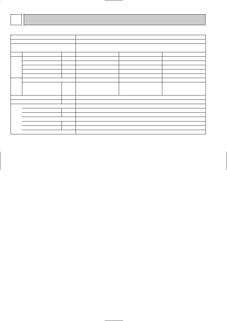
3 SPECIFICATION
Indoor model
Function
Power supply
Capacity Air flow(High/Med.W/LowW)
Electrical |
data |
Power outlet |
|
Running current |
|||
|
|
||
|
|
Power input |
|
|
|
Power factor |
|
|
|
Fan motor current |
|
Fan |
motor |
Model |
|
Winding |
|||
|
|
||
|
|
resistance(at20:) |
|
|
|
Dimensions WOHOD |
|
|
|
Weight |
|
|
|
Air direction |
|
|
|
Sound level(High/Med.W/LowW) |
|
Special |
remarks |
Fan speed(High/Med.W/LowW) |
|
Thermistor RT11(at25:) |
|||
|
|
Fan speed regulator |
|
|
|
Thermistor RT12(at25:) |
|
|
|
Remote controller model |
|
|
|
|
|
MCFH-GA35VB |
MCFH-GA50VB |
MCFH-GA60VB |
||||||
|
Cooling |
|
Heating |
Cooling |
|
Heating |
Cooling |
|
Heating |
|
|
|
|
Single phase |
|
|
|
||
|
|
|
|
230V, 50Hz |
|
|
|
||
K /h |
780/636W/492W |
840/696W/570W |
840/744W/642W |
||||||
A |
|
10 |
|
10 |
|
10 |
|||
A |
|
0.30 |
|
0.36 |
|
0.36 |
|||
W |
|
66 |
|
80 |
|
80 |
|||
% |
|
96 |
|
97 |
|
97 |
|||
A |
|
0.30 |
|
0.36 |
|
0.36 |
|||
|
RB4V25-AC |
RB4V36-AC |
RB4V36-DB |
||||||
|
WHT-BLK 182.2 BLK-YLW 68.9 WHT-BLK 82.9 BLK-YLW 65.6 |
WHT-BLK 84.0 BLK-YLW 46.2 |
|||||||
"YLW-BLU 47.5 BLU-BRN 31.5 YLW-BLU 36.0 BLU-BRN 27.0 YLW-BLU 37.2 BLU-BRN 45.2
|
BRN-RED 22.9 |
BRN-RED 13.7 |
BRN-RED 13.6 |
mm |
|
1100 650 180 |
|
kg |
25 |
25 |
25 |
|
5 |
5 |
5 |
dB |
46/41W/36W |
48/44W/39W |
48/45W/42W |
rpm |
1,240/1,060/845 |
1,320/1,145/960 |
1,320/1,190/1,060 |
|
3 |
3 |
3 |
k" |
10 |
10 |
10 |
k" |
10 |
10 |
10 |
|
KM04M |
KM04M |
KM04M |
|
|
|
|
NOTE: Test conditions are based on ISO 5151 |
|
|
Cooling : Indoor DB27°C WB19°C |
Heating : Indoor |
DB20°C WB 15°C |
Outdoor DB35°C WB(24°C) |
Outdoor |
DB 7°C WB 6°C |
Indoor-Outdoor piping length : 5 m |
|
|
w Reference value |
|
|
4

4 NOISE CRITERIA CURVES
MCFH-GA35VB |
MCFH-GA50VB |
FAN SPEED FUNCTION SPL(dB(A)) |
LINE |
|
|
|
|
High |
COOLING |
46 |
|
|
|
|
|
|
|
|
|
HEATING |
|
|
|
|
|||
|
|
|
|
|
|
|
|
|
|
||
|
|
|
|
|
Test conditions, |
|
|
|
|
||
|
|
|
|
|
|
Cooling : DB 27: WB 19:\ |
|
|
|||
|
90 |
|
|
|
|
Heating : DB 20: WB 15: |
|
90 |
|||
|
|
|
|
|
|
|
|
|
|
||
BAR |
|
|
|
|
|
|
|
|
|
BAR |
|
MICRO |
80 |
|
|
|
|
|
|
|
|
MICRO |
80 |
|
|
|
|
|
|
|
|
|
|
||
dB re 0.0002 |
70 |
|
|
|
|
|
|
|
NC-70 |
dB re 0.0002 |
70 |
|
|
|
|
|
|
|
|
|
|||
60 |
|
|
|
|
|
|
|
|
60 |
||
LEVEL, |
|
|
|
|
|
|
|
|
LEVEL, |
||
|
|
|
|
|
|
|
|
NC-60 |
|
||
50 |
|
|
|
|
|
|
|
|
50 |
||
PRESSURE |
|
|
|
|
|
|
|
|
PRESSURE |
||
|
|
|
|
|
|
|
|
NC-50 |
|
||
40 |
|
|
|
|
|
|
|
|
40 |
||
|
|
|
|
|
|
|
|
NC-40 |
|
||
SOUND |
|
|
|
|
|
|
|
|
SOUND |
|
|
30 |
|
|
|
|
|
|
|
|
30 |
||
|
|
|
|
|
|
|
|
NC-30 |
|
||
BAND |
|
|
|
|
|
|
|
|
BAND |
|
|
20 |
APPROXIMATE |
|
|
|
|
|
|
20 |
|||
OCTAVE |
THRESHOLD OF |
|
|
|
|
|
OCTAVE |
||||
|
|
|
|
|
|
|
|||||
|
HEARING FOR |
|
|
|
|
|
NC-20 |
|
|||
|
CONTINUOUS |
|
|
|
|
|
|
||||
|
|
|
|
|
|
|
|
||||
10 |
NOISE |
|
|
|
|
|
|
|
10 |
||
|
|
|
|
|
|
|
|
||||
|
63 |
125 |
250 |
500 |
1000 |
2000 |
4000 |
8000 |
|
||
|
|
|
|
||||||||
FAN SPEED FUNCTION SPL(dB(A)) |
LINE |
|
|
High |
COOLING |
48 |
|
|
|
|
|
HEATING |
|
|
|||
|
|
|
|
|
|
||
|
|
|
Test conditions, |
|
|
||
|
|
|
|
Cooling : DB 27: WB 19:\ |
|||
|
|
|
|
Heating : DB 20: WB 15: |
|||
|
|
|
|
|
|
|
NC-70 |
|
|
|
|
|
|
|
NC-60 |
|
|
|
|
|
|
|
NC-50 |
|
|
|
|
|
|
|
NC-40 |
|
|
|
|
|
|
|
NC-30 |
APPROXIMATE |
|
|
|
|
|
|
|
THRESHOLD OF |
|
|
|
|
|
||
HEARING FOR |
|
|
|
|
|
NC-20 |
|
CONTINUOUS |
|
|
|
|
|
||
|
|
|
|
|
|
||
NOISE |
|
|
|
|
|
|
|
63 |
125 |
250 |
500 |
1000 |
2000 |
4000 |
8000 |
BAND CENTER FREQUENCIES, Hz |
BAND CENTER FREQUENCIES, Hz |
MCFH-GA60VB
FAN SPEED FUNCTION SPL(dB(A)) |
LINE |
|
|
|
|
High |
COOLING |
48 |
|
|
|
|
|
|
|
HEATING |
|
|
|||
|
|
|
|
|
|
|
|
||
|
|
|
|
|
Test conditions, |
|
|
||
|
|
|
|
|
|
Cooling : DB 27: WB 19:\ |
|||
|
90 |
|
|
|
|
Heating : DB 20: WB 15: |
|||
|
|
|
|
|
|
|
|
|
|
BAR |
|
|
|
|
|
|
|
|
|
MICRO |
80 |
|
|
|
|
|
|
|
|
|
|
|
|
|
|
|
|
|
|
dB re 0.0002 |
70 |
|
|
|
|
|
|
|
NC-70 |
|
|
|
|
|
|
|
|
||
60 |
|
|
|
|
|
|
|
|
|
LEVEL, |
|
|
|
|
|
|
|
|
|
|
|
|
|
|
|
|
|
NC-60 |
|
50 |
|
|
|
|
|
|
|
|
|
PRESSURE |
|
|
|
|
|
|
|
|
|
|
|
|
|
|
|
|
|
NC-50 |
|
40 |
|
|
|
|
|
|
|
|
|
|
|
|
|
|
|
|
|
NC-40 |
|
SOUND |
|
|
|
|
|
|
|
|
|
30 |
|
|
|
|
|
|
|
|
|
|
|
|
|
|
|
|
|
NC-30 |
|
BAND |
|
|
|
|
|
|
|
|
|
20 |
APPROXIMATE |
|
|
|
|
|
|
||
OCTAVE |
THRESHOLD OF |
|
|
|
|
|
|||
|
|
|
|
|
|
||||
|
HEARING FOR |
|
|
|
|
|
NC-20 |
||
|
CONTINUOUS |
|
|
|
|
|
|||
|
|
|
|
|
|
|
|||
10 |
NOISE |
|
|
|
|
|
|
|
|
|
|
|
|
|
|
|
|
||
|
63 |
125 |
250 |
500 |
1000 |
2000 |
4000 |
8000 |
|
|
|
||||||||
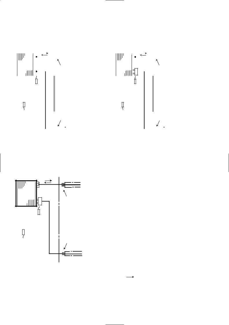
BAND CENTER FREQUENCIES, Hz
INDOOR UNIT
MICROPHONE
WALL
1m
1m
5
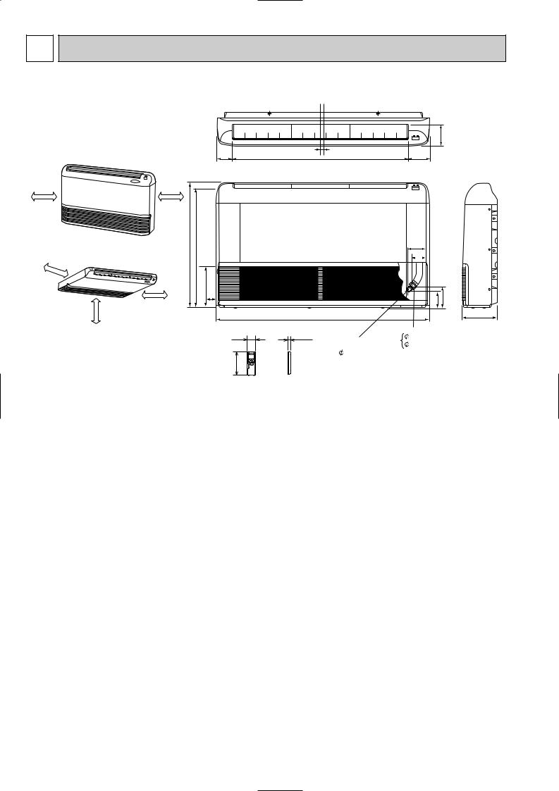
5 OUTLINES AND DIMENSIONS
MCFH-GA35VB
MCFH-GA50VB
MCFH-GA60VB
80.8
(When installed on the floor)
50cm or more |
50cm or more |
|
|
|
650 |
616.5 |
5 |
0c |
(When installed on the ceiling) |
|
|
|
|
m |
|
|
|
|
or |
|
|
|
|
m |
|
|
|
|
ore |
|
170 |
|
|
|
|
|
|
|
more |
50cm or more |
42.5 |
|
|
100cm or |
|
|
58
162
Unit: mm
114
906 |
16 |
112.8 |
|
93
|
77 |
|
|
113 |
143 |
1100 |
|
180 |
19 |
Gas line |
|
12.7 (MCFH-GA35/GA50VB) |
||
Liquid line |
15.88 (MCFH-GA60VB) |
|
6.35 |
|
|
Wireless remote controller
6
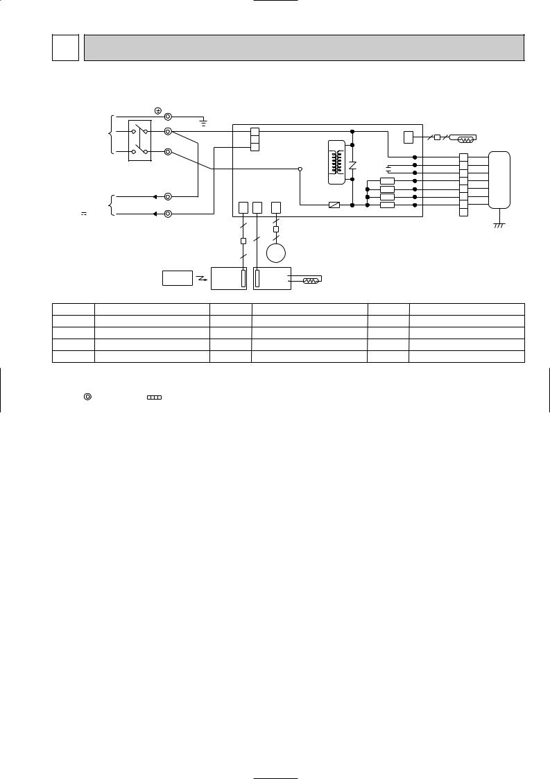
6 WIRING DIAGRAM
MCFH-GA35VB MCFH-GA50VB MCFH-GA60VB
|
TB1 |
|
|
|
|
|
|
|
|
|
PE |
GRN/YLW |
|
|
|
|
|
|
|
POWER |
N |
|
BLU |
|
|
|
|
|
|
SUPPLY |
|
1 |
|
|
|
|
CN |
||
~/N 230V |
|
|
|
|
HIC1 |
|
|
||
|
|
|
2 |
|
|
|
|||
50Hz |
|
|
RED |
|
|
|
|
112 |
|
L |
|
3 |
|
|
|
|
|
||
|
|
|
|
|
|
LDCOM |
|||
|
|
|
CN201 |
|
NR11 |
||||
|
|
|
|
|
|
||||
|
CIRCUIT BREAKER |
|
BRN |
|
TAB12 |
|
LDC11 |
||
|
|
|
|
|
|
C11 LDC12 |
|||
|
|
|
|
|
|
|
|||
|
|
|
|
|
|
|
|
X144 LDFH |
|
|
TB2 |
BLU |
|
|
|
|
|
SR143 |
LDFM |
TO OUTDOOR |
|
|
|
|
|
LDFL |
|||
N |
|
|
|
|
F11 |
|
SR142 |
||
UNIT |
|
|
|
|
|
|
|
||
CONNECTING |
3 |
|
CN |
CN |
CN |
|
|
SR141 LDFVL |
|
12V |
|
101 |
113 |
151 |
ELECTRONIC CONTROL P.C BOARD |
||||
|
|
|
|
6 |
|
|
|
|
|
|
|
|
5 |
|
|
|
|
|
|
|
|
|
|
|
|
|
|
|
|
|
|
|
|
4 |
5 |
|
|
|
|
|
|
|
5 |
|
MV |
|
|
|
|
|
REMOTE |
DISP/ |
SW/THERMO |
|
|
|
|
||
|
RECEIVER |
P.C.BOARD |
|
|
|
|
|||
|
CONTROLLER |
|
|
|
|
||||
|
P.C.BOARD |
|
|
|
|
|
|
||
|
|
|
|
|
RT11 |
|
|
|
|
|
|
|
|
|
|
|
|
|
|
2 |
2 |
|
RT12 |
|
|
|
|
|
WHT |
1 |
WHT |
|
ORN |
2 |
ORN |
|
RED |
3 |
RED |
|
BLK |
4 |
BLK MF |
|
YLW |
5 |
YLW |
|
BLU |
6 |
BLU |
|
BRN |
7 |
BRN |
|
|
8 |
GRN/YLW |
SYMBOL |
|
NAME |
SYMBOL |
NAME |
SYMBOL |
NAME |
C11 |
INDOOR FAN CAPACITOR |
MV |
VANE MOTOR |
SR141~SR143 SOLID STATE RELAY |
||
F11 |
FUSE (3.15A) |
|
NR11 |
VARISTOR |
TB1, TB2 |
TERMINAL BLOCK |
HIC1 |
DC/DC CONVERTER |
RT11 |
ROOM TEMPERATURE THERMISTOR |
X144 |
RELAY |
|
MF |
INDOOR FAN MOTOR(INNER FUSE) |
RT12 |
INDOOR COIL THERMISTOR |
|
|
|
NOTES: 1.About the outdoor side electric wiring refer to the outdoor unit electric wiring diagram for servicing. |
|
|
||||
2.Use copper conductors only. (For field wiring) |
|
|
|
|||
3.Symbols below indicate. |
|
|
|
|
||
|
: Terminal block |
: Connector |
|
|
|
|
7
7 |
|
|
REFRIGERANT SYSTEM DIAGRAM |
|
|
|
|
|
|
|
|
|
|
|
|
|
|
|
|
|
|
|
|
|
|
|
|||||||||||||||||||||||
|
|
|
|
|
|
|
|
|
|
|
|
|
|
|
|
|
|
|
|
|
|
|
|
|
|
|
|
|
|
|
|
|
|
|
|
|
|
|
|
|
|
|
|
|
|
|
|
|
|
|
|
|
|
|
|
|
|
|
|
|
|
|
|
|
|
|
|
|
|
|
|
|
|
|
|
|
|
|
|
|
|
|
|
|
|
|
|
|
|
|
|
|
|
|
|
|
|
|
Unit : mm |
MCFH-GA35VB |
MCFH-GA50VB |
||||||||||||||||||||||||||||||||||||||||||||||||
|
|
|
|
|
|
|
|
|
|
|
Refrigerant pipe [12.7 |
|
|
|
|
|
|
|
|
|
|
|
Refrigerant pipe [12.7 |
||||||||||||||||||||||||||
|
|
|
|
|
|
|
|
|
|
|
(with heat insulator) |
|
|
|
|
|
|
|
|
|
|
|
(with heat insulator) |
||||||||||||||||||||||||||
|
|
|
|
|
|
|
|
|
|
|
|
|
|
|
|
|
|
|
|
|
|||||||||||||||||||||||||||||
|
|
|
|
|
|
|
|
|
|
|
|
|
|
|
|
|
|
|
|
|
|
|
|
|
|
|
|
|
|
|
|
|
|
|
|
|
|
|
|
|
|
|
|
|
|
|
|
||
|
Indoor |
|
|
|
|
|
|
|
|
|
|
|
|
|
|
|
|
|
|
|
|
|
|
Indoor |
|
|
|
|
|
|
|
|
|
|
|
|
|
|
|
|
|
|
|
|
|
|
|
||
|
heat |
|
Distributor |
|
Flared connection |
|
heat |
Distributor |
|
|
Flared connection |
||||||||||||||||||||||||||||||||||||||
|
exchanger |
|
|
exchanger |
|
|
|||||||||||||||||||||||||||||||||||||||||||
|
|
|
|
|
|
|
|
|
|
|
|
|
|
|
|
|
|
|
|
|
|
|
|
|
|
|
|
|
|
|
|
|
|
|
|
|
|
|
|
|
|
|
|
|
|
|
|
|
|
|
|
|
|
|
|
|
|
|
|
|
|
|
|
|
|
|
|
|
|
|
|
|
|
|
|
|
|
|
|
|
|
|
|
|
|
|
|
|
|
|
|
|
|
|
|
|
|
|
|
|
|
|
|
|
|
|
|
|
|
|
|
|
|
|
|
|
|
|
|
|
|
|
|
|
|
|
|
|
|
|
|
|
|
|
|
|
|
|
|
|
|
|
|
|
|
|
|
|
|
|
|
|
|
|
|
|
|
|
|
|
|
|
|
|
|
|
|
|
|
|
|
|
|
|
|
|
|
|
|
|
|
|
|
|
|
|
|
|
|
|
|
|
|
|
|
|
|
|
|
|
Indoor coil |
|
|
|
|
|
|
|
|
|
|
|
|
|
|
|
|
|
|
|
|
|
Indoor coil |
|
|
|
|
|
|
|
|
|
|
|
|
|
|
|
|
|
|
|
|
|
|
|
|||
|
thermistor |
|
|
|
|
|
|
|
|
|
|
|
|
|
|
|
|
|
|
|
|
|
thermistor |
|
|
|
|
|
|
|
|
|
|
|
|
|
|
|
|
|
|
|
|
|
|
|
|||
|
RT12 |
|
|
|
|
|
|
|
|
|
|
|
|
|
|
|
|
|
|
|
|
|
|
RT12 |
|
|
|
|
|
|
|
|
|
|
|
|
|
|
|
|
|
|
|
|
|
|
|
||
Room temperature |
|
|
|
|
|
|
|
|
|
|
|
Room temperature |
|
|
|
|
|
|
|
|
|
|
|
thermistor |
|
|
|
|
|
|
|
|
|
|
|
thermistor |
|
|
|
|
|
|
|
|
|
|
|
|
|
|
|
|
|
|
|
|
|
|
|
|
|
|
|
|
|
|
|
|
|
||
RT11 |
|
Flared connection |
RT11 |
|
|
Flared connection |
|||||||||||||||||
|
|
|
|
|
|
|
|
|
|
|
|
|
|
|
|
|
|
|
|
|
|
|
|
|
|
|
|
|
|
|
|
|
|
|
|
|
|
|
|
|
|
|
|
|
|
|
|
|
|
Refrigerant pipe |
|
|
|
Refrigerant pipe |
|||||||||||||||||
|
|
[6.35 |
|
|
|
|
|
|
|
|
|
|
[6.35 |
|
|
|
|
|
|
||||
|
|
(with heat insulator) |
|
|
|
(with heat insulator) |
|||||||||||||||||
MCFH-GA60VB
|
Refrigerant pipe [15.88 |
|
(with heat insulator) |
Indoor |
|
heat |
Distributor |
exchanger |
Flared connection |
|
|
Indoor coil |
|
thermistor |
|
RT12 |
|
Room temperature |
Flared connection |
thermistor |
|
RT11 |
|
Refrigerant pipe [6.35
(with heat insulator)
 Refrigerant flow in cooling
Refrigerant flow in heating
8
8 SERVICE FUNCTIONS
MCFH-GA35VB MCFH-GA50VB MCFH-GA60VB
8-1. TIMER SHORT MODE
For service, set time can be shortened by short circuit of JPG and JPS on the electronic control P.C. board. The time will be shortened as follows. (Refer to 9-6.)
3-minutes time delay : 3-minutes 3-seconds Set time : 1 minute 1-second
Set time : 3 minute 3-second (It takes 3 minutes for the compressor to start operation. However, the starting time is shortened by short circuit of JPG and JPS.)
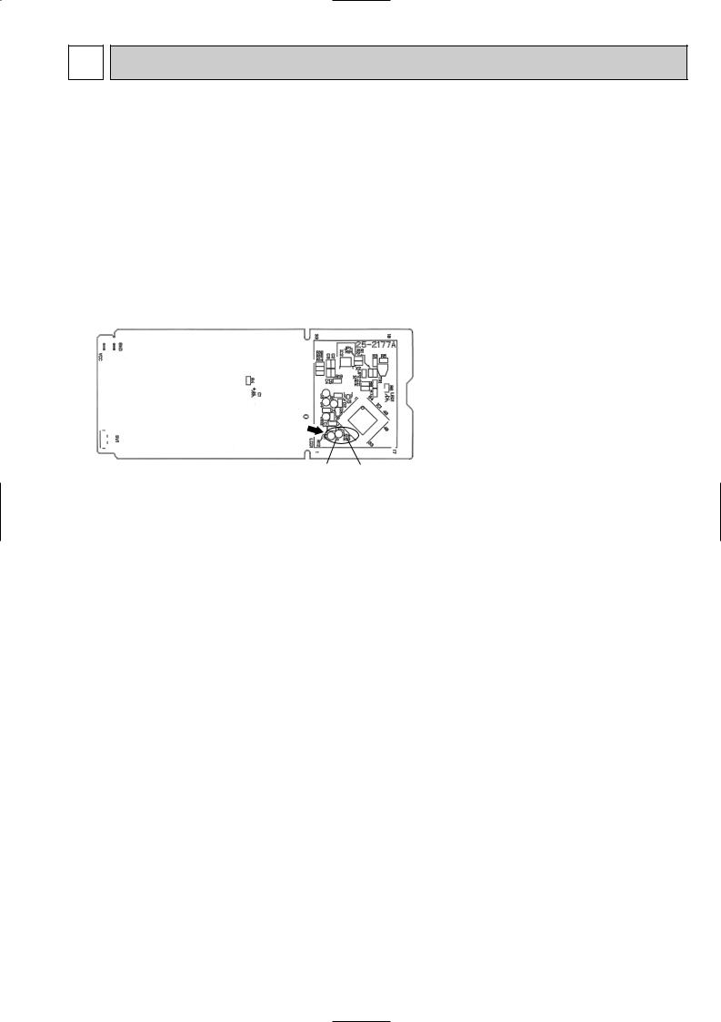
8-2. P.C. BOARD MODIFICATION FOR INDIVIDUAL OPERATION
A maximum of 4 indoor units with wireless remote controllers can be used in a room. In this case, to operate each indoor unit individually by each remote controller, P.C. boards of remote controller must be modified according to the number of the indoor unit.
How to modify the remote controller P.C. board
Remove batteries before modification. The board has a print as shown below;
NOTE : For remodelling, take out the batteries and press the OPERATE/STOP(ON/OFF) button twice or 3 times at first.
After finish remodelling, put back the batteries then press the RESET button.
J1 J2
The P.C. board has the print “J1” and “J2”. Solder “J1” and “J2” according to the number of indoor unit as shown in Table 1. After modification, press the RESET button.
Table1.
|
1 unit operation |
2 units operation |
3 units operation |
4 units operation |
|
|
|
|
|
No. 1 unit |
No modification |
Same as at left |
Same as at left |
Same as at left |
|
|
|
|
|
No. 2 unit |
– |
Solder J1 |
Same as at left |
Same as at left |
|
|
|
|
|
No. 3 unit |
– |
– |
Solder J2 |
Same as at left |
|
|
|
|
|
No. 4 unit |
– |
– |
– |
Solder both J1 and J2 |
|
|
|
|
|
How to set the remote controller exclusively for particular indoor unit
After you turn the breaker ON, the first remote controller that sends the signal to the indoor unit will be regarded as the remote controller for the indoor unit.
The indoor unit only accepts the signal from the remote controller that has been assigned to the indoor unit once they are set.
The setting will be cancelled if the breaker has turned OFF, or the power supply has shut down. Please conduct the above setting once again after the power has restored.
9
 Loading...