


Note:
●Refer to OB196 REVISED EDITION-A for the details of
MCFH-24NV- EA and MUCFH-24NV- EA .
FLOOR AND CEILING TYPE AIR CONDITIONERS
No. OB266
SERVICE MANUAL
Wireless type Models
MCFH-24NV-
EB (WH) ·MUCFH-24NVEB-
(When installed on the floor)
(When installed on the ceiling)
CONTENTS
1.TECHNICAL CHANGES ··················
2.PART NAMES AND FUNCTIONS··············
3.SPECIFICATION·····················
4.OUTLINES AND DIMENSIONS ···············
5.WIRING DIAGRAM ····················
6.REFRIGERANT SYSTEM DIAGRAM ············
7.PERFORMANCE CURVES ················
8.MICROPROCESSOR CONTROL ··············
9.SERVICE FUNCTIONS ··················
10.TROUBLESHOOTING···················
11.DISASSEMBLY INSTRUCTIONS··············
12.PARTS LIST·······················
13.OPTIONAL PARTS····················

1 
 TECHNICAL CHANGES
MCFH-24NV - EA →MCFH-24NV - EB
1. Only model name has changed.
MUCFH-24NV - EA →MUCFH-24NV - EB
1.Ball valve has changed to stop valve.
2.Deicer P.C. board has changed.
2 
 PART NAMES AND FUNCTIONS
MCFH-24NV - EB
INDOOR UNIT
(When installed on the floor)
Operation section
(When the air inlet grille is opened.)
Emergency operation switch
ACCESSORIES
|
Item |
Q'ty |
|
Installation plate |
2 |
|
Unit fixing screw 5 o 12mm |
2 |
|
Wireless remote controller |
1 |
|
Remote controller mounting hardware |
1 |
|
Fixing screw for 3.5 o 16mm (Black) |
2 |
|
Battery (AAA) for remote controller |
2 |
|
Drain hose |
1 |
|
Drain pipe cover |
1 |
|
Knockout cover |
1 |
|
Screw for 4 o 10mm |
2 |
2
Vertical vanes
Horizontal vane
Operation indicator lamp
Receiving section
Front panel
Air cleaning filter (whilte bellows type)(option)
Air inlet
Air filter
Deodorizing filter (gray sponge type)(option)
 Remote controller
(When installed on the ceiling)
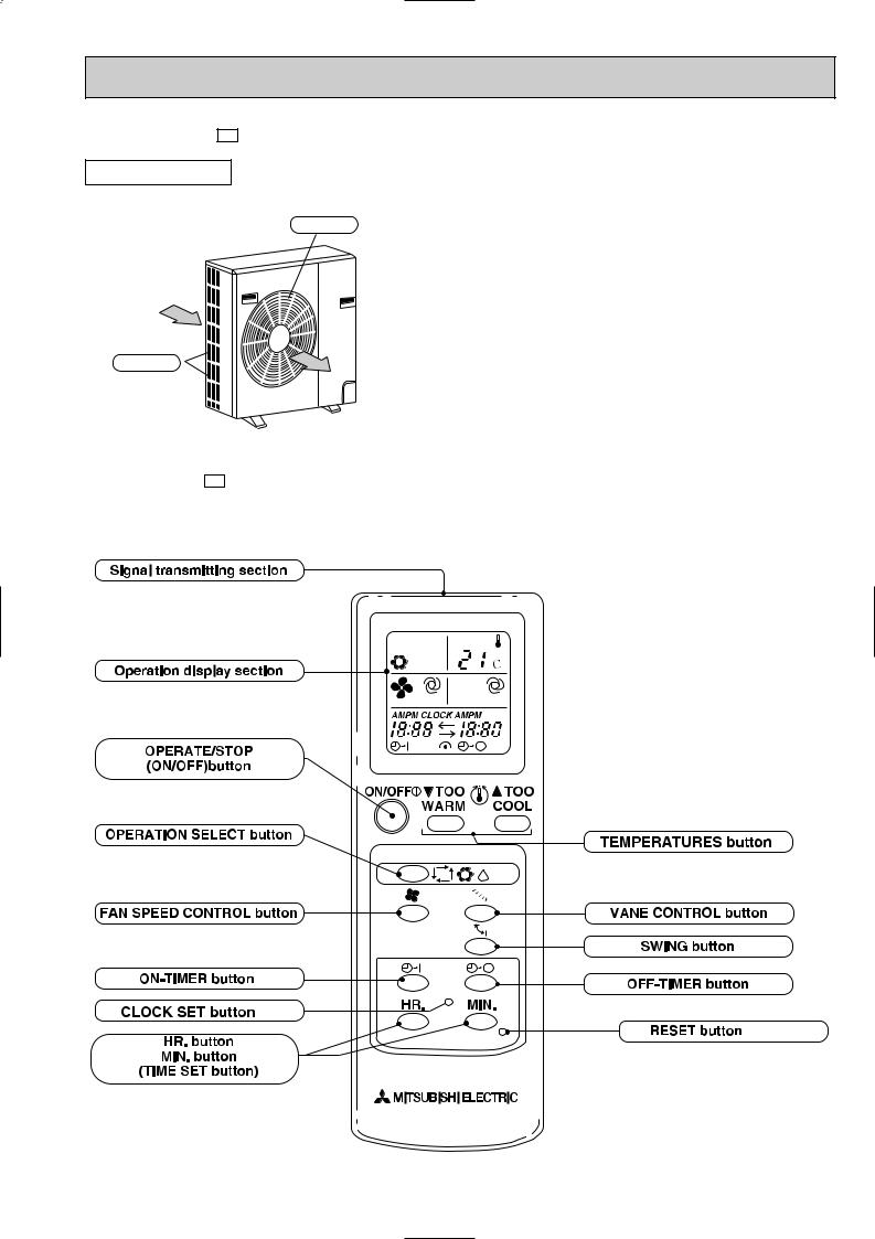
MUCFH-24NV - EB
OUTDOOR UNIT
Air outlet
Air inlet
MCFH-24NV - EB
g
CLOCK
RESET
3
3 
 SPECIFICATION
Indoor model
Function
Capacity |
Power supply |
|
|
Capacity |
kW |
||
|
|||
|
Air flow(High) |
K /h |
|
|
Dehumidification |
L/h |
|
|
Power outlet |
A |
|
Electrical data |
Running current |
A |
|
Power input |
W |
||
|
|||
|
Auxiliary heater |
A(kW) |
|
|
Power factor |
% |
|
|
Starting current |
A |
|
|
Fan motor current |
A |
|
Coefficient of performance(C.O.P) |
|||
Fan motor |
Model |
|
|
Winding |
|||
|
|
|
|
|
resistance(at20:) |
" |
|
|
Dimensions WOHOD |
mm |
|
|
Weight |
kg |
|
Special remarks |
Air direction |
|
|
Sound level (High) |
dB |
||
|
|||
|
Fan speed (High) |
rpm |
|
|
Fan speed regulator |
|
|
|
Thermistor RT11(at25:) |
k" |
|
|
Thermistor RT12(at25:) |
k" |
|
|
Outdoor model |
|
|
Capacity Air flow (High) |
K /h |
||
Electrical data |
Fan motor current |
A |
|
|
Compressor motor current |
A |
|
Compressor |
Model |
|
|
Output |
W |
||
|
|||
|
Winding |
" |
|
|
resistance(at20:) |
|
|
Fan motor |
Model |
|
|
Winding |
" |
||
|
resistance(at20:) |
|
|
|
Dimensions WOHOD |
mm |
|
|
Weight |
kg |
|
|
Sound level(High) |
dB |
|
|
Fan speed(High) |
rpm |
|
|
Fan speed regulator |
|
|
Special remarks |
Refrigerant filling |
kg |
|
capacity(R22) |
|||
|
|||
|
|
||
|
Refrigerating oil (Model) |
cc |
|
|
Thermistor RT61(at0:) |
k" |
|
|
Thermistor RT63(at0:) |
k" |
|
NOTE:Test conditions are based on ISO 5151 Cooling : Indoor DB27°C WB19°C
Outdoor DB35°C WB(24°C)
|
MCFH-24NV- EB |
Cooling |
Heating |
Single phase 220 - 240 V, 50Hz |
|
6.0 |
6.2 |
|
840 |
3.1 |
- |
|
25 |
12.5-11.7 |
11.7-11.3 |
2,720-2,750 |
2,540-2,650 |
- |
- |
99-98 |
98-98 |
59
0.36
2.21-2.18 2.44-2.34
RB4V36-AB
WHT-BLK 82.9 BLK-YLW 65.6
YLW-BLU 36.0 BLUBRN 27.0
BRN-RED 13.7
1,100 650 180
26
5
48-48
1,310-1,330
3
10
10
MUCFH-24NV- EB
2,640-2,760
11.56-10.76 |
10.76-10.36 |
0.58 |
0.58 |
NH-47VMDT |
|
2,200 |
|
C-R 0.96 |
C-S 2.07 |
RA6V85-AA
WHT-BLK 62.7 BLK-YLW 30.2
YLW-RED 62.9
870 850 295
72
53
720-750
2
2.40
1.2(MS32N1)
33.18
33.18
Heating : Indoor DB20°C WB15°C
Outdoor DB 7°C WB 6°C
4
4 |
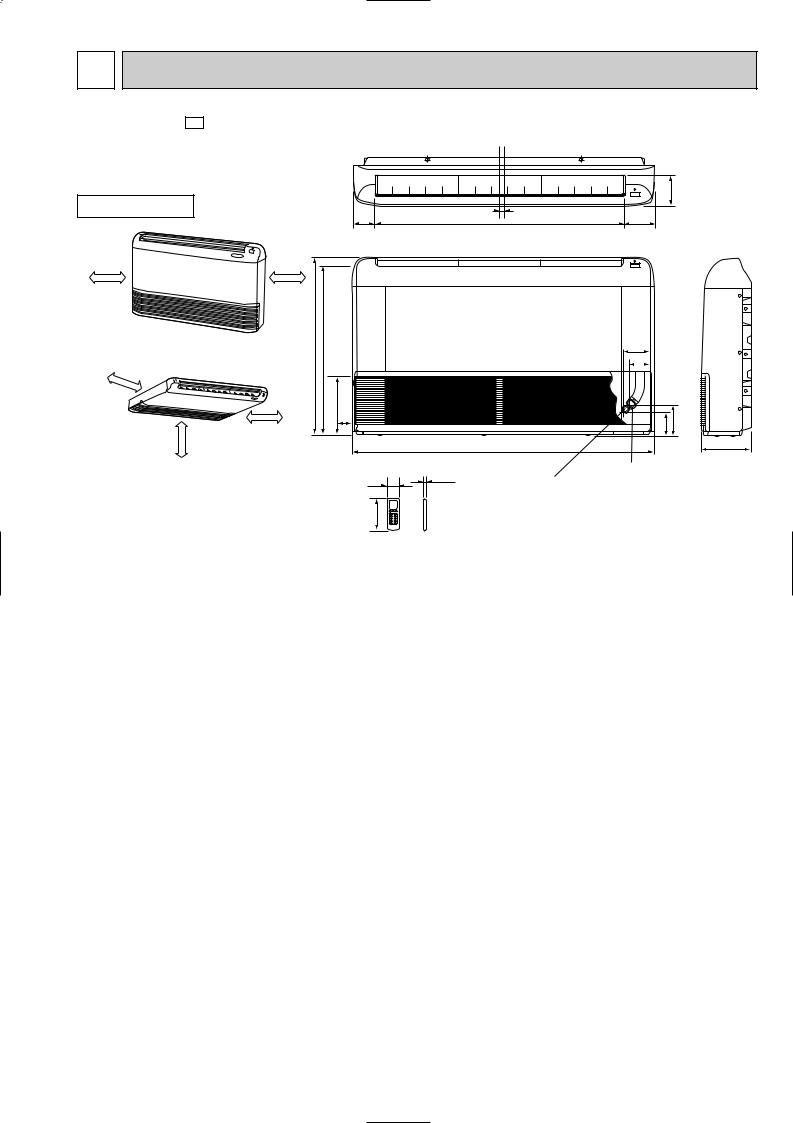
OUTLINES AND DIMENSIONS |
|
|
|
MCFH-24NV - EB |
|
|
Unit: mm |
|
INDOOR UNIT |
|
|
114 |
|
|
16 |
|
||
|
80.8 |
906 |
112.8 |
|
|
|
|||
|
(When installed on the floor) |
|
|
|
50cm or more |
50cm or more |
|
|
|
50cm |
(When installed on the ceiling) |
|
or |
|
more |
moreor100cm |
50cm or more |
650 |
616.5 |
|
93 |
|
|
|
|
|
|
|
|
|
77 |
|
|
170 |
|
|
|
|
42.5 |
|
113 |
143 |
|
|
1100 |
|
180 |
|
|
17.5 |
Gas line |
|
|
56 |
{15.88 |
|
|
|
|
|
Liquid line |
|
|
160 |
|
{9.52 |
|
|
|
|
|
5
6
|
185 |
|
185 |
||
|
(7-9/32) |
500(19-11/16) |
(7-9/32) |
||
Outdoor Unit-Necessary surrounding clearance |
|
|
|
|
|
(Concentrated installation) |
The upper side must be open. |
|
|
Air intake |
|
|
|
|
|||
|
|
|
|
|
|
|
|
Air intake |
100 |
10 |
200 |
Air outlet |
||
|
For 10 units or less |
1000 |
17 |
|
39.5 27.5 330(13) |
362(14-1/4) |
15 |
|
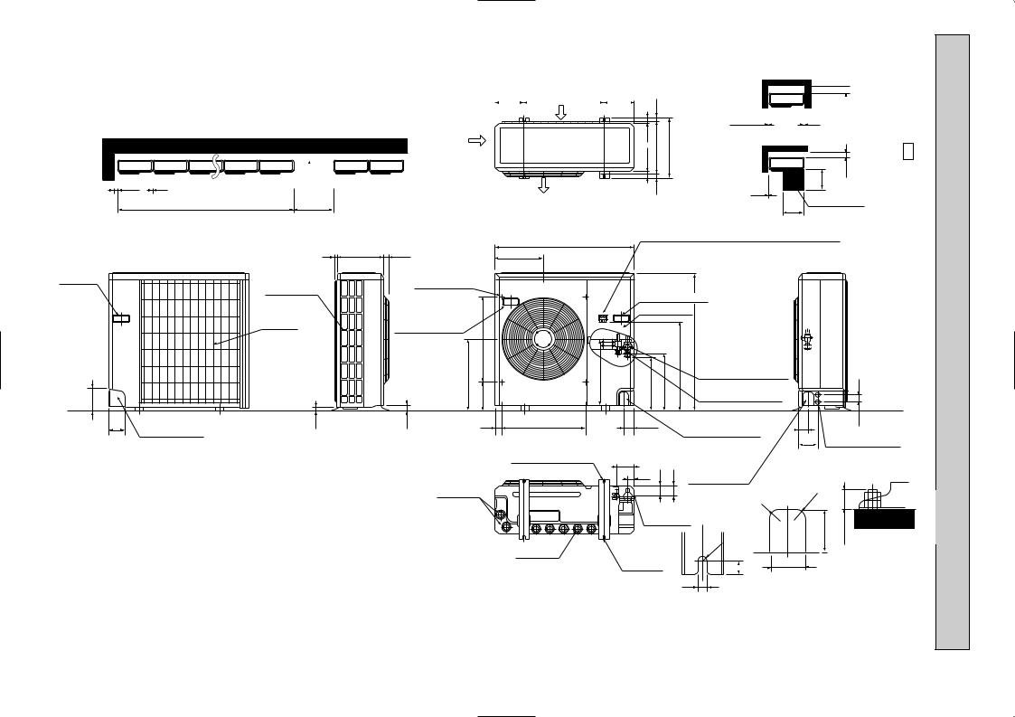
Outdoor Unit-Necessary surrounding clearance
200
Note:Allow adequate 10 
 10 upper clearance
Front opening
500 |
150 |
10 |
|
Service space |
|
500 |
|
EB - 24NV-MUCFH
870(34-1/4)
|
|
7 295(11-5/8) 24(1) |
302 |
|
|
|
|
Handle |
|
Outlet guide |
|
for moving |
|
|
|
|
installation hole |
|
|
|
Side air intake |
|
|
|
|
|
|
|
Rear fresh |
|
|
|
air intake |
Handle for moving |
|
|
|
|
|
|
|
|
524 |
|
|
441 |
403 |
138 |
|
|
179 |
Terminal block for indoor and outdoor unit connection
Handle for moving
Service panel
|
553 |
850(33-7/16) |
Refrigerant-pipe flared |
337 |
352 |
|
connection [15.88 5/8F |
|
Refrigerant-pipe flared |
||
|
|
|
connection [9.52 3/8F |
45
95 |
23 |
33 |
40 |
524 |
60 |
|
Knock out hole |
|
60 |
53 |
|
|
Rear piping hole |
|
|
|
|
|
|
for front piping |
|
120 |
Knock out holes for |
|
|
|
|
|
|
|
|
(refrigerant,drainage |
power line 2-[27 |
||
|
|
|
|
2-12o23 Oval holes |
|
|
|
and wiring) |
|
|
|
|
|
|
|
104 |
|
|
Knock out hole |
|
|
|
|
|
|
|
|
(standard bolt M10) |
|
|
|
|
|
||
|
|
|
|
33 |
42 |
45 |
|
|
|
||
|
|
|
|
|
for right piping |
|
|
|
|||
|
|
|
|
|
|
|
|
|
|
|
|
|
|
|
Drain hole |
|
|
|
|
(refrigerant,drainage |
R20 |
|
|
|
|
|
|
|
|
|
and wiring) |
R20 |
|
||
|
|
|
|
|
|
|
|
|
|||
|
|
|
|
|
|
|
|
|
|
||
|
|
|
|
|
Bottom |
|
|
|
|||
|
|
|
|
|
|
|
80 |
max.25 |
|||
|
|
|
|
|
piping hole |
|
|||||
|
|
|
|
|
|
|
|
||||
Drain hole |
2-U-shaped |
|
R6 |
|
Standard bolt length |
|
|
|
|||
notched |
|
|
|
||
|
|
|
|
65 |
|
|
holes |
|
|
17 |
|
|
|
|
|
||
|
|
|
|
|
|
|
|
12 |
|
|
Front right piping holes- |
|
|
|
|
detail figures |
|
|
|
|
|
|
mm Unit:
5 WIRING DIAGRAM
INDOOR UNIT |
|
MODEL MCFH-24NV- EB |
|
|
|
|
|||
|
TB |
|
|
|
|
|
|
|
|
POWER |
|
GRN/YLW |
|
|
|
|
|
|
|
SUPPLY |
N |
|
|
|
|
|
|
|
|
CORD |
BLU |
|
|
|
|
|
|
|
|
~/N |
|
|
|
|
|
|
|
CN |
|
220-240V |
L |
|
|
|
|
HIC1 |
|
|
112 |
|
|
|
|
|
|
|
|||
50Hz |
WHT |
|
|
|
|
|
|
|
|
|
|
|
|
|
|
|
LDCOM |
||
|
|
|
|
|
3 |
3 52C |
NR11 |
C11 |
|
|
|
|
|
|
LDC12 |
||||
|
|
|
|
|
4 |
|
|
LDC11 |
|
|
|
|
|
|
2 |
|
|
|
|
|
N BLU |
|
|
1 |
|
|
SR144 LDFH |
||
TO OUTDOOR |
|
CN201 |
TRANS |
|
SR143 LDFM |
||||
UNIT |
2 |
WHT |
|
|
BRN |
F11 |
|
SR142 LDFL |
|
CONNECTING |
|
|
CN |
CN |
CN |
|
|
SR141 LDFVL |
|
|
3 |
|
|
|
|
|
|||
|
RED |
101 |
113 |
151 ELECTRONIC CONTROL P.C BOARD |
|||||
GRN/YLW |
5 |
|
6 |
|
|
|
|
||
|
|
|
|
|
|
||||
|
|
|
|
4 |
6 |
|
|
|
|
|
|
|
5 |
|
MV |
|
|
|
|
|
|
REMOTE |
DISP/ |
SW/THERMO |
|
|
|
|
|
|
|
RECEIVER |
P.C.BOARD |
|
|
|
|
||
|
|
CONTROLLER |
|
|
|
|
|||
|
|
P.C.BOARD |
|
|
|
|
|
|
|
|
|
|
|
|
|
|
|
|
|
2 |
2 |
|
RT12 |
|
|
|
|
|
WHT |
1 |
WHT |
|
ORN |
2 |
ORN |
|
RED |
3 |
RED |
|
YLWBLK |
4 |
YLWBLK MF |
|
BLU |
5 |
BLU |
|
6 |
||
|
BRN 7 |
BRN |
|
|
|
8 |
GRN/YLW |
|
|
|
|
RT11
SYMBOL |
NAME |
SYMBOL |
NAME |
SYMBOL |
NAME |
C11 |
FAN MOTOR CAPACITOR |
MV |
VANE MOTOR |
SR142~SR144 |
SOLID STATE RELAY |
F11 |
FUSE (3.15A) |
NR11 |
VARISTOR |
TB |
TERMINAL BLOCK |
HIC1 |
DC/DC CONVERTER |
RT11 |
ROOM TEMP. THERMISTOR |
52C |
CONTACTOR |
MF |
FAN MOTOR(INNER PROTECTOR) |
RT12 |
COIL TEMP. THERMISTOR |
|
|
NOTE:1. About the outdoor side electric wiring, refer to the outdoor unit electric wiring diagram for servicing. |
|
VG79B063H01 |
|||
2.Use copper conductors only.(For field wiring)
3.Symbols below indicate;
:Terminal block,


 : Connector
OUTDOOR UNIT
CONNECTING
TO INDOOR UNIT
MODEL MUCFH-24NV- EB
|
|
|
RT61 |
RT63 |
|
|
MF |
|
|
|
|
||
|
|
|
|
|
WHT |
|
|
|
|
|
|||
|
|
|
|
|
|
YLW |
BLK |
ORN |
RED |
|
|
|
|
|
|
|
|
|
6 |
5 |
4 |
3 |
2 |
1 RED |
|
|
|
|
|
|
|
|
|
YLW |
BLK |
WHT |
|
ORN |
C2 |
|
|
|
|
|
|
|
|
|
|
|
|
|
|
||
|
|
CN661 |
CN662 |
|
1 |
2 |
3 CN711 |
CN721 |
|
|
|||
|
|
|
|
|
SR62 |
|
|
|
|
|
1 |
|
|
|
|
|
|
|
|
|
|
|
X62 |
2 |
|
21S4 |
|
|
|
|
|
|
SR61 |
|
|
|
|
|
|||
|
|
|
|
|
|
|
|
|
|
COM |
NO 3 |
|
|
|
|
|
X62 |
|
|
|
|
|
|
X52 |
TAB52 |
|
|
|
|
|
|
|
|
|
|
|
|
COM |
NO |
|
|
|
|
|
|
|
|
|
|
|
|
F61 |
|
|
|
|
|
|
X52 |
T61 |
|
|
|
NR61 |
1 |
|
|
||
TB |
|
|
|
|
|
|
|
|
|
3 |
|
|
|
|
|
|
|
DEICER PC BOARD CN730 5 |
RED |
BLU WHT BLU |
|||||||
3 |
|
|
|
|
|
|
|
|
|
|
|
||
|
|
|
|
|
|
|
|
|
|
|
|
|
|
2 |
|
|
|
|
|
|
|
|
|
|
|
|
|
N |
|
|
|
|
|
|
|
|
|
|
|
|
|
GRN/YLW |
WHT |
DSAR |
WHT 1 |
2 |
|
|
|
|
|
WHT |
|
|
|
|
|
52C |
|
|
|
|
|
|
|
|
|||
|
|
|
|
|
|
|
|
|
|
|
|
|
|
|
|
|
|
|
|
|
|
|
|
C1 |
RED S |
|
|
|
|
|
|
|
|
|
|
|
|
|
|
|
|
|
|
|
BLU |
|
|
|
|
|
|
|
BLK MC C |
||
|
|
|
BLU |
|
A2 52C A1 |
|
|
|
|
R |
|
|
|
|
|
|
|
|
|
|
|
|
|
|
|||
SYMBOL |
NAME |
SYMBOL |
NAME |
SYMBOL |
NAME |
C1 |
COMPRESSOR CAPACITOR |
NR61 |
VARISTOR |
T61 |
TRANSFORMER |
C2 |
FAN MOTOR CAPACITOR |
RT61 |
DEFROST TEMPERATURE THERMISTOR |
X52 |
CONTACTOR |
DSAR |
SURGE ABSORBER |
RT63 |
AMBIENT TEMPERATURE THERMISTOR |
X62 |
R.V. COIL RELAY |
F61 |
FUSE(3.15A) |
SR61 |
SOLID STATE RELAY |
21S4 |
R.V. COIL |
MC |
COMPRESSOR (INNER PROTECTOR) |
SR62 |
SOLID STATE RELAY |
52 |
COMPRESSOR CONTACTOR |
MF |
FAN MOTOR (INNER PROTECTOR) |
TB |
TERMINAL BLOCK |
|
|
NOTES: 1.Use copper conductors only (For field wiring). |
SG79J186H01 |
|
2.Since the indoor and outdoor unit connecting wires have polarity, connect them according to the numbers (3,2,N). |
|
|
3.Symbols below indicate. |
|
|
:Terminal block, |
:Connector |
|
|
7 |
|
|
6 |
|
|
REFRIGERANT SYSTEM DIAGRAM |
|
|
|
|
|
|
|
|
|
|
|
|
|
|
|
|
|
|
|
|
|
|
|||||||||||||||||||||||||||||||||||||||||||||
|
|
|
|
|
|
|
|
|
|
|
|
|
|
|
|
|
|
|
|
|
|
|
|
|
|
|
|
|
|
|
|
|
|
|
|
|
|
|
|
|
|
|
|
|
|
|
|
|
|
|
|
|
|
|
|
|
|
|
|
|
|
|
|
|
|
|
|
|
|
|
|
|
|
MCFH-24NV- EB |
|
|
|
|
|
|
|
|
|
|
|
|
|
|
|
|
|
|
|
|
|
|
|
|
|
|
|
|
|
|
|
|
|
|
|
|
|
|
|
|
|
|
|
|
|
|
MUCFH-24NV- EB |
|
|||||||||||||||||||||
|
|
|
|
|
|
|
|
|
|
|
|
|
|
|
|
|
|
|
|
|
|
|
|
|
|
|
|
|
|
|
|
|
|
|
|
|
|
|
|
|
|
|
|
|
|
|
|
|
|
|
|
|
|
|
|
|
|
|
|
|
|
|
|
|
|
|
|||||
|
|
INDOOR UNIT |
|
Refrigerant pipe [15.88 |
|
4-way valve |
|
|
|
|
|
|
|
OUTDOOR UNIT |
|
||||||||||||||||||||||||||||||||||||||||||||||||||||||||
|
|
|
|
|
|
|
|
|
|
|
|
(Option) |
|
|
|
|
|
|
|
|
|
|
|
|
|
|
|
|
|
|
|
|
|
|
|
|
|
|
|
|
|
|
|
|
|
|
|
||||||||||||||||||||||||
|
|
|
|
|
|
|
|
|
|
|
|
(with heat insulator) |
|
|
|
Muffler |
|
|
|
|
|
|
|
|
|
|
|
|
|
|
|
|
|
|
|
|
|
|
|
|
|
|
|
|
|
||||||||||||||||||||||||||
|
|
|
|
|
|
|
|
|
|
|
|
|
|
|
|
|
|
|
|
|
|
|
|
|
|
|
|
|
|
|
|
|
|
|
|
|
|
|
|
|
|
|
|||||||||||||||||||||||||||||
|
|
Indoor |
|
|
|
|
|
|
|
|
|
|
|
|
|
|
|
|
|
|
|
|
|
|
|
|
|
|
|
|
|
|
|
|
Stop valve |
|
|
|
|
|
|
|
|
|
|
|
|
|
|
|
|
|
|
|
|
|
|
|
|
|
|
|
|
|
|||||||
|
|
|
|
|
|
|
|
|
|
|
|
|
|
|
|
|
|
|
|
|
|
|
|
|
|
|
|
|
|
|
|
|
|
|
|
|
|
|
|
|
|
|
|
|
|
|
|
|
|
|
|
|
|
|
|
|
|
|
|
|
|
|
|||||||||
|
|
|
|
|
|
|
|
|
|
|
|
|
|
|
|
|
|
|
|
|
|
|
|
|
|
|
|
|
|
|
|
|
|
|
|
|
|
|
|
|
|
|
|
|
|
|
|
|
|
|
|
|
|
|
|
|
|
|
|
|
|
|
|||||||||
|
|
|
|
|
|
|
|
|
|
|
|
|
|
|
|
|
|
|
|
|
|
|
|
|
|
|
|
|
|
|
|
|
|
|
|
|
|
|
|
|
|
|
|
|
|
|
|
|
|
|
|
|
|
|
|
|
|
|
|
|
|
|
|||||||||
|
|
heat |
|
Distributor |
|
|
|
|
|
|
|
|
|
|
|
|
|
|
|
|
|
|
|
|
|
|
|
|
|
|
(with service port) |
|
|
|
|
|
Strainer |
|
|
|
|
|
|
|
Outdoor |
|
|||||||||||||||||||||||||
|
|
exchanger |
|
|
Flared connection |
|
|
|
|
|
|
|
|
|
|
|
|
|
|
|
|
|
|
|
|
|
|
|
|
|
heat |
|
|||||||||||||||||||||||||||||||||||||||
|
|
|
|
|
|
|
|
|
|
|
|
|
|
|
|
|
|
|
|
|
|
|
|
|
|
|
|
|
|
|
|
|
|
|
|
|
|
exchanger |
|
||||||||||||||||||||||||||||||||
|
|
Coil temperature |
|
|
|
|
|
|
|
|
|
|
|
|
|
|
|
|
|
|
|
|
|
|
|
|
|
|
|
|
|
|
|
|
|
|
|
|
|
|
|
|
|
|
|
|
|
|
|
|
|
|
|
|
|
|
|
|
|
|
|
|
|
|
|||||||
|
|
|
|
|
|
|
|
|
|
|
|
|
|
|
|
|
|
|
|
|
|
|
|
|
|
|
|
|
|
|
|
|
|
|
|
|
|
|
|
|
|
|
|
|
|
|
|
|
|
|
|
|
|
|
|
|
|
|
|
|
|
|
|
||||||||
|
|
thermistor |
|
|
|
|
|
|
|
|
|
|
|
|
|
|
|
|
|
|
|
|
|
|
|
|
|
|
|
|
|
|
|
|
|
|
|
|
|
|
|
|
|
|
|
|
|
|
|
|
|
|
|
|
|
|
|
|
|
|
|
|
|
|
|
|
|
|
|
||
|
|
RT12 |
|
|
|
|
|
|
|
|
|
|
|
|
|
|
|
|
|
|
|
|
|
|
|
|
|
|
|
|
|
|
|
|
|
|
|
|
|
|
|
|
|
|
|
|
|
|
|
|
|
|
|
|
|
|
|
|
|
|
|
|
|
|
|
|
|
|
|
||
|
|
|
|
|
|
|
|
|
|
|
|
|
|
|
|
|
|
|
|
|
|
|
|
|
|
|
|
|
|
|
|
|
|
|
|
|
|
|
|
|
|
|
|
|
|
|
|
|
|
|
|
Compressor |
|
|
|
|
|
|
|
||||||||||||
|
|
|
|
|
|
|
|
|
|
|
|
|
|
|
|
|
|
|
|
|
|
|
|
|
|
|
|
|
|
|
|
|
|
|
|
|
|
|
|
|
Accumulator |
|
|
|
|
|
|
|
|
|
|||||||||||||||||||||
|
|
|
|
|
|
|
|
|
|
|
|
|
|
|
|
|
|
|
|
|
|
|
|
|
|
|
|
|
|
|
|
|
|
|
|
|
|
|
|
|
|
|
|
|
|
|
|
|
|
|
|
|
|
|
|
|
|
|
|
|
|
|
|||||||||
|
|
|
|
|
|
|
|
|
|
|
|
|
|
|
|
|
|
|
|
|
|
|
|
|
|
|
|
|
|
|
|
|
|
|
|
|
|
|
|
|
|
|
Discharge pressure |
|
|||||||||||||||||||||||||||
|
|
|
|
|
|
|
|
|
|
|
|
|
|
|
|
|
|
|
|
|
|
|
|
|
|
|
|
|
|
|
|
|
|
|
|
|
|
|
|
|
|
|
|
Capillary tube |
|
|
|
||||||||||||||||||||||||
|
|
|
|
|
|
|
|
|
|
|
|
|
|
|
|
|
|
|
|
|
|
|
|
|
|
|
|
|
|
|
|
|
|
|
|
|
|
|
|
|
Check |
|
|
|
regurator open |
|
|||||||||||||||||||||||||
|
|
|
|
|
|
|
|
|
|
|
|
|
|
|
|
|
|
|
|
|
|
|
|
|
|
|
|
|
|
|
|
|
|
|
|
|
|
|
|
|
|
|
|
|
|||||||||||||||||||||||||||
|
Room temperature |
|
|
|
Flared connection |
|
|
|
|
|
[3.0o[1.6o350 |
|
|
23.5Of/F |
|
||||||||||||||||||||||||||||||||||||||||||||||||||||||||
|
|
|
|
|
|
|
|
|
|
|
|
||||||||||||||||||||||||||||||||||||||||||||||||||||||||||||
|
thermistor |
|
|
|
|
|
|
|
|
|
|
|
|
valve |
|
|
|
|
|
|
|
|
|
|
|
|
|
|
|
|
|
|
|
|
|
|
|
|
|
|
|
|
|
||||||||||||||||||||||||||||
|
RT11 |
|
|
|
|
|
|
|
|
|
|
|
|
|
|
|
|
|
|
|
|
|
|
|
|
|
|
|
|
|
|
|
|
|
|
|
|
|
|
Capillary tube [3.0o[2.0o350 |
|
|
|
|
|
|
|
|
|
|
|
|
|
||||||||||||||||||
|
|
|
|
|
|
|
|
|
|
|
|
|
|
|
|
|
|
|
|
|
|
|
|
|
|
|
|
|
|
|
|
|
|
|
|
|
|
|
Strainer |
|
|
|
|
|
|
|
|
|
|
|
|||||||||||||||||||||
|
|
|
|
|
|
|
|
|
|
|
|
|
|
|
|
|
|
|
|
|
|
|
|
|
|
|
|
|
|
|
|
|
|
|
|
|
|
|
|
|
|
|
|
|
|
|
|
|
|
|
|
|
|
|
|
|
|
|
|
|
|
|
|
|
|
|
|
||||
|
|
|
|
|
|
|
|
|
|
|
|
|
|
|
|
|
|
|
|
|
|
|
|
|
|
|
|
|
|
|
|
|
|
|
|
|
|
|
|
|
|
|
|
|
|
|
|
|
|
|
|
|
|
|
|
|
|
|
|
|
|
|
|
|
|
|
|
|
|
|
|
|
|
|
|
|
|
|
|
|
|
|
|
|
|
Refrigerant pipe |
Stop valve |
|
|
|
|
|
|
|
|
|
|
|
|
Capillary tube |
|
||||||||||||||||||||||||||||||||||||||||||
|
|
|
|
|
|
|
|
|
|
|
|
|
|
(Option) [9.52 |
|
|
|
|
|
|
|
Check |
|
|
|
|
|
[4.0o[2.4o200 |
|
||||||||||||||||||||||||||||||||||||||||||
|
|
|
|
|
|
|
|
|
|
|
|
|
|
(with heat insulator) |
|
|
|
|
|
|
|
|
|
|
|
|
Refrigerant flow in cooling |
|
|||||||||||||||||||||||||||||||||||||||||||
|
|
|
|
|
|
|
|
|
|
|
|
|
|
|
|
|
|
|
|
|
|
|
|
|
|
|
|
|
|
|
|
|
|
|
|
|
|
|
|
|
|
|
|
valve |
|
|
|
|
|
|
|||||||||||||||||||||
|
|
|
|
|
|
|
|
|
|
|
|
|
|
|
|
|
|
|
|
|
|
|
|
|
|
|
|
|
|
|
|
|
|
|
|
|
|
|
|
|
|
|
|
|
|
|
|
|
|
||||||||||||||||||||||
|
|
|
|
|
|
|
|
|
|
|
|
|
|
|
|
|
|
|
|
|
|
|
|
|
|
|
|
|
|
|
|
|
|
|
|
|
|
|
|
|
|
|
|
|
|
|
|
|
Refrigerant flow in heating |
|
|||||||||||||||||||||
|
|
|
|
|
|
|
|
|
|
|
|
|
|
|
|
|
|
|
|
|
|
|
|
|
|
|
|
|
|
|
|
|
|
|
|
|
|
|
|
|
|
|
|
|
|
|
|
|
|
|
|
|
|
|
|
||||||||||||||||
|
MAX. REFRIGERANT PIPING LENGTH & MAX. HEIGHT DIFFERENCE |
|
|
|
|
|
|
|
|
|
|
|
|
|
|
|
|
|
|||||||||||||||||||||||||||||||||||||||||||||||||||||
|
|
|
|
|
|
|
|
|
|
|
|
|
|
|
|
|
|
|
|
|
|
|
|
|
|
|
|
|
|
|
|
|
|
|
|
|
|
|
|
|
|
|
|
|
|
|
|
|
|
|
|
|
|
|
|
|
|
|
|
|
|
|
|
|
|
|
|
|
|
|
|
|
|
|
|
|
Models |
|
|
|
|
Refrigerant piping MAX. length : m |
|
|
|
Piping size O.D. : mm |
|
||||||||||||||||||||||||||||||||||||||||||||||||||||||||
|
|
|
|
|
|
|
|
|
|
|
|
|
|
|
|
|
|
|
|
|
|
|
|
|
|
|
|
|
|
|
A |
|
|
Gas |
|
|
|
|
|
|
|
|
|
|
|
|
Liquid |
|
|||||||||||||||||||||||
|
|
|
|
|
|
|
|
|
|
|
|
|
|
|
|
|
|
|
|
|
|
|
|
|
|
|
|
|
|
|
|
|
|
|
|
|
|
|
|
|
|
|
|
|
|
|
|
|
|
|
|
||||||||||||||||||||
|
|
|
|
|
|
|
|
|
|
|
|
|
|
|
|
|
|
|
|
|
|
|
|
|
|
|
|
|
|
|
|
|
|
|
|
|
|
|
|
|
|
|
|
|
|
|
|
|
|
|
|
|
|
|
|
|
|
|
|
|
|
|
|
|
|
|
|
|
|
||
|
|
|
MCFH-24NV - EB |
|
|
|
|
|
|
|
|
|
|
|
|
|
|
|
|
|
|
|
|
|
|
|
|
|
|
15 |
|
|
|
|
|
{15.88 |
|
|
|
|
|
|
|
{9.52 |
|
|
|
|
|
||||||||||||||||||||||
wIt does not matter which unit is higher.
Height difference * |
5m |
Max. |
|
A:Refrigerant piping Max.length
15m
ADDITIONAL REFRIGERANT CHARGE (R22 : g)
If pipe length exceeds 7m, additional refrigerant (R22) charge is required
Models |
Outdoor unit:precharged |
|
Refrigerant piping length (one way) |
|
|||||||
(up to 7m) |
7m |
8m |
9m |
10m |
11m |
12m |
13m |
14m |
15m |
||
|
|||||||||||
|
|
|
|
|
|
|
|
|
|
|
|
MCFH-24NV - EB |
2,400 |
0 |
65 |
130 |
195 |
260 |
325 |
390 |
455 |
520 |
|
Calculation : og=65g/mo(Refrigerant piping length minus 7m)
8

7 
 PERFORMANCE CURVES
The standard data contained in these specifications apply only to the operation of the air conditioner under normal condition. Operating conditions vary according to the areas where these units are installed. The following information has been provided to clarify the operating characteristics of the air conditioner under the conditions indicated by the performance curve.
(1)GUARANTEED VOLTAGE
198~264V, 50Hz
(2)AIR FLOW
Air flow should be set at MAX..
(3) MAIN READINGS
COOLING |
HEATING |
||
(1) |
Indoor intake air wet-bulb temperature : ˚CWB |
(1) |
Indoor intake air dry-bulb temperature : ˚CDB |
(2) |
Indoor outlet air wet-bulb temperature : ˚CWB |
(2) |
Indoor outlet air dry-bulb temperature : ˚CDB |
(3) |
Outdoor intake air dry-bulb temperature : ˚CDB |
(3) |
Outdoor intake air wet-bulb temperature : ˚CWB |
(4) Total input : W |
(4) Total input : W |
||
Indoor air wet/dry-bulb temperature difference on the left side of the chart on page 16 shows the difference between the indoor intake air wet/dry-bulb temperature and the indoor outlet air wet/dry-bulb temperature for your reference at service.
How to measure the indoor air wet-bulb/dry-bulb temperature difference
1.Attach at least 2 sets of wet-and-dry-bulb thermometers to the indoor air inlet as shown in the figure, and at least 2 sets of wet- and-dry-bulb thermometers to the indoor air outlet. The thermometers must be attached to the position where air speed is high.
2.Attach at least 2 sets of wet-and-dry-bulb thermometers to the outdoor air inlet.
Cover the thermometers to prevent direct rays of the sun.
3.Check that the air filter is cleaned.
4.Open windows and doors of the room.
5.Press the EMERGENCY OPERATION switch once(twice) to start the EMERGENCY COOL(HEAT) MODE.
6.When system stabilizes after more than 15 minutes, measure temperature and take an average temperature.
7.10 minutes later, measure temperature again and check that the temperature does not change.
INDOOR UNIT |
Wet-and dry-bulb |
OUTDOOR UNIT |
Air out |
thermometers |
|
Air in
Wet-and dry-bulb thermometers BACK VIEW
FRONT VIEW
14.7
13.4
12.1
10.9
9.7
8.5
MCFH-24NV- EB
29.0
26.7
24.5
22.3
20.0
17.8
15.6
13.4
MCFH-24NV- EB
9
OUTDOOR LOW PRESSURE AND OUTDOOR UNIT CURRENT
COOL operation
1 Both indoor and outdoor units are under the same temperature/humidity condition.
Dry Bulb temperature (˚C) |
Relative humidity (%) |
20 |
50 |
25 |
60 |
30 |
70 |
2 Air flow should be set at MAX..
3 The unit of pressure has been changed to MPa on the international system of units(SI unit system). The converted score against the traditional unit system can be gotten according to the formula below.
1(MPa • G) =10.2(kgf/f • G)
MUCFH-24NV- EB
(kgf/F• G) (MPa•G) |
|
|
|
|
|
||||||||||
|
7 |
|
0.7 |
|
|
|
|
|
|
|
|||||
pressure |
6 |
|
|
0.6 |
|
|
|
|
|
|
|
||||
|
|
|
|
|
|
|
|||||||||
|
|
|
|
|
|
|
|
|
|||||||
5 |
|
|
|
|
|
|
0.5 |
|
|
|
|
|
|
|
|
|
|
|
|
|
|
|
|
|
|
|
|
||||
|
|
|
|
|
|
|
|
|
|
|
|||||
low |
|
|
|
|
|
|
|
|
|
|
220-240V |
|
|
|
|
4 |
|
|
|
|
|
0.4 |
|
|
|
|
|
|
|
||
Outdoor |
|
|
|
|
|
|
|
|
|
|
|||||
|
|
|
|
|
|
|
|||||||||
|
|
|
|
|
|
|
|
|
|
||||||
|
|
|
|
|
|
|
|
|
|
|
|
|
|
|
|
|
3 |
0.3 |
|
|
|
|
|
|
|
||||||
|
2 |
|
|
0.2 |
|
|
|
|
|
|
|
||||
|
|
15 18 20 |
25 |
30 32 35(:) |
|||||||||||
|
|
50 |
60 |
70 |
(%) |
||||||||||
Outdoor unit current (A)
13
220V
12
240V
11
10
9
8
7
15 18 20 |
25 |
30 |
32 35(:) |
50 |
60 |
70 |
(%) |
Ambient temperature (:) |
Ambient temperature (:) |
Ambient humidity (%) |
Ambient humidity (%) |
HEAT operation
Condition Indoor : Dry bulb temerature 20.0: |
Outdoor : Dry bulb temerature 7, 15, 21: |
Wet bulb temerature 14.5: |
Wet bulb temerature 6, 13, 15.3: |
Outdoor unit current (A)
13 |
|
|
220V |
||
|
||
|
240V |
11
9
7
0 2 5 |
10 |
15 |
20 |
25(:) |
Ambient temperature (:)
10
8 MICROPROCESSOR CONTROL
MCFH-24NV - EB MUCFH-24NV - EB
WIRELESS REMOTE CONTROLLER
g
CLOCK
RESET
INDOOR UNIT DISPLAY SECTION
OPERATION INDICATOR lamp
The operation indicator at the right side of the indoor unit indicates the operation state.
Operation Indicator |
lighted |
|
|
|
not lighted |
|
|
Difference |
|
|
|
between set |
|
Indication |
Operation state |
temperatuer |
|
|
|
and room |
|
|
|
temperature |
|
|
|
|
|
|
This shows that the air |
|
|
|
conditioner is operating |
|
|
|
to reach the target temp- |
Approx. 2 : |
|
|
erature. |
or more |
|
|
Please wait until the |
|
|
|
target temperature is |
|
|
|
obtained. |
|
|
|
|
|
|
|
This shows that the |
|
|
|
room temperature is |
Approx. 2 : |
|
|
approaching the target |
or less |
|
|
temperature. |
||
|
|
|
|
|
|
|
|
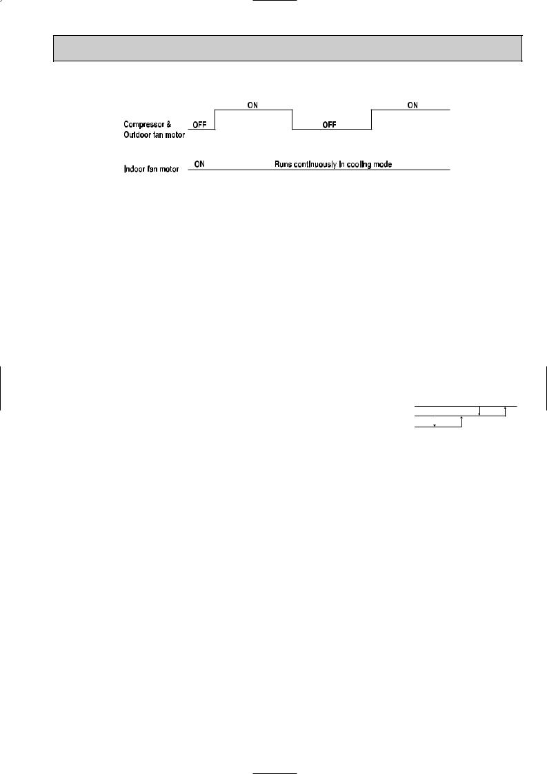
Once the operation mode are set, the same operation mode can be repeated by simply turning the OPERATE/STOP button ON.
Indoor unit receives the signal with a beep tone.
When the system turns off, 3-minute time delay will operate to protect system from overload and compressor will not restart for 3 minutes.
8-1. “I FEEL CONTROL”(  ) OPERATION
(1)Press OPERATE/STOP button on the remote controller. OPERATION INDICATOR lamp of the indoor unit will turn on with a beep tone.
(2)Press OPERATION SELECT button to set “I FEEL CONTROL”(
 ). Then a beep tone is heard.
(3)The operation mode is determined by the initial room temperature at start-up of the operation.
Initial room temperature |
mode |
|
|
|
|
more than 25°C |
COOL mode of |
|
“I FEEL CONTROL” |
||
|
||
23.0°C to 25°C |
DRY mode of |
|
“I FEEL CONTROL” |
||
|
||
less than 23°C |
HEAT mode of |
|
“I FEEL CONTROL” |
||
|
●Once the mode is fixed, the mode will not change by room temperature afterwards.
●Under the ON-TIMER( ) timer operation, mode is
determined according to the room temperature as the operation starts.
●When the system is stopped with the OPERATE/ STOP button on the remote controller, and restarted within 2 hours in “I FEEL CONTROL”(
 ) mode, the system operates in previous mode automatically regardless of the room temperature.
Example |
|
|
||
Previous operation |
Restart |
|||
COOL mode of |
COOL mode of |
|||
“I FEEL CONTROL” |
“I FEEL CONTROL” |
|||
or COOL mode |
|
|
||
|
|
|
|
|
|
|
|
|
|
|
|
|
|
|
● When the system is restarted after 2 hours, the operation
mode is determined by the initial room temperature at start-up of the operation. Restart
COOL or DRY or HEAT mode of “I FEEL CONTROL” that is determined by
initial room temperature at start-up of the operation.
11
(4) The initial set temperature is decided by the initial room temperature.
Model |
Initial room temperature |
Initial set temperature |
||
|
|
|
|
|
|
26°C or more |
24°C |
|
|
COOL mode of |
|
|
w1 |
|
“I FEEL CONTROL” |
|
|
||
|
|
|
||
|
26°C or less |
Initial room temperature |
|
|
|
minus 2°C |
|
||
|
|
|
||
|
|
|
|
|
DRY mode of |
23°C to 25°C |
Initial room temperature |
||
“I FEEL CONTROL” |
minus 2°C |
|||
|
||||
|
|
|
|
|
HEAT mode of |
23°C or less |
26°C |
||
“I FEEL CONTROL” |
||||
|
|
|
||
|
|
|
|
|
w1 After the system restarts by the remote controller, the system operates with the previous set temperature regardless of the initial set temperature.
The set temperature is calculated by the previous set temperature.
(5)TEMPERATURE buttons
In “I FEEL CONTROL” mode, set temperature is decided by the microprocessor based on the room temperature.
In addition, set temperature can be controlled by or TOO WARM or TOO COOL buttons when you feel too warm or too cool. Each pressing the TOO WARM or TOO COOL button ,indoor unit receives the signal a beep tone.
●Fuzzy control
When the TOO COOL or TOO WARM button is pressed, the microprocessor changes the set temperature, considering the room temperature, the frequency of pressing TOO COOL or TOO WARM button and the user’s preference to heat or cold. So this is called “Fuzzy control”, and works only in “I FEEL CONTROL” operation.
In DRY mode of “I FEEL CONTROL”, the set temperature doesn’t change.
▲TOO
COOL … To raise the set temperature 1~2 degrees(°C)
▼ TOO
WARM … To lower the set temperature 1~2 degrees(°C)
12
— COOL mode of “I FEEL CONTROL” —
NOTE : Coil frost prevention during COOL mode of “I FEEL CONTROL”
There are two types of controls in coil frost prevention as follows.
1Temperature control
When the indoor coil thermistor RT12 reads -1°C or below, the coil frost prevention mode starts immediately. However the coil frost prevention will not work for 5 minutes after the compressor starts.
During the coil frost prevention compressor stops and the indoor fan operates at the set speed for 5 minutes. After that, if RT12 still reads below -1°C, this mode is prolonged until the RT12 reads over -1°C.
2Time control
When the three conditions below have been satisfied for 1 hour and 45 minutes, compressor stops for 3 minutes.
a.Compressor has been continuously operating.
b.Indoor fan speed is Low or Med..
c.Room temperature is below 26°C.
When compressor stops ,the accumulated time is cancelled and when compressor restarts, time counting starts from the beginning.
Time counting also stops temporarily when the indoor fan speed becomes High or the room temperature exceeds 26°C. However, when two of the above conditions (b.And c.) are satisfied again time accumulation is resumed.
●Indoor fan operates at the set speed by FAN SPEED CONTROL button. Followings are the fan speed in AUTO.
Initial temperature difference |
Fan speed |
|||
Room temperature minus set temperature : 2 degrees or more·········································High |
|
|
||
Room temperature minus set temperature : 1 degree or more and less than 2 degrees···Med. |
|
|
||
|
|
|||
Room temperature minus set temperature : less than 1 degree·········································Low |
|
|
||
1deg. |
||||
|
|
|||
2deg. 4deg.
1.7deg.
—DRY mode of “I FEEL CONTROL”—
The system for dry operation uses the same refrigerant circuit as the cooling circuit.
The compressor and the indoor fan are controlled by the temperature and the microprocessor.
By such controls, indoor air flow amounts will be reduced in order to lower humidity without much room temperature decrease.
The operation of the compressor and indoor fan is as follows.
1.When the room temperature is 23°C or over:
Compressor operates by temperature control and time control.
1 Set temperature is controlled to fall 2°C above from initial set temperature.
2When the thermostat is ON, the compressor repeats 8 minutes ON and 3 minutes OFF. When the thermostat is OFF, the compressor repeats 4 minutes OFF and 1 minute ON. Indoor fan and outdoor fan operate in the same cycle as the compressor.
2.When the room temperature is under 23°C.
When the thermostat is ON, the compressor repeats 2 minutes ON and 3 minutes OFF. When the thermostat is OFF, the compressor repeats 4 minutes OFF and 1 minute ON.
13
|
|
|
|
|
|
|
|
|
|
|
|
|
|
|
|
|
|
|
|
|
Operation time chart |
|
|
|
|
|
|
|
|
|
|
|
|
|
|
|
|
|
|
|
|
Example |
|
|
1st ON |
|
|
|
|
|
|
|
|
|
|
ON |
||||||
|
|
|
|
|
|
|
|
|
|
|
|
|
|
|||||||
Thermostat |
|
OFF |
|
|
|
|
|
|
|
|
|
|
OFF |
|
|
|
|
|
||
|
|
|
|
|
|
|
|
|
|
|
|
|
|
|
||||||
|
|
|
|
|
|
|
|
|
|
|
|
|
|
|
|
|
|
|||
|
|
|
|
|
|
|
|
|
|
|
|
|
|
|
|
|
|
|
||
|
|
|
|
ON |
|
ON |
|
|
ON |
|||||||||||
|
|
|
|
|
|
|
|
|
|
|
|
|
|
|
|
|
|
|||
Indoor fan |
|
OFF |
|
|
|
OFF |
|
|
|
OFF |
|
|
|
|
|
|
|
|
|
|
|
|
|
|
ON |
|
ON |
|
|
ON |
|
||||||||||
Outdoor fan |
|
OFF |
|
|
|
OFF |
|
|
|
OFF |
|
|
|
|
|
|
|
|
|
|
|
|
|
|
|
|
|
|
|
|
|
|
|
|
|||||||
compressor |
|
|
|
8 min. |
|
3 min. |
|
4 min. 1 min. |
||||||||||||
|
|
|
|
|
|
|||||||||||||||
|
|
|
|
|
|
|
|
|
|
|
|
|
|
|
|
|
|
|
|
|
NOTE ● Coil frost prevention during DRY mode of “I FEEL CONTROL”
The operation is same as that of coil frost prevention during COOL mode of “I FEEL CONTROL”. However the indoor fan speed becomes the set speed or Low.
— HEAT mode of “I FEEL CONTROL” —
1. Indoor fan speed control |
|
|
|
|
|
|
|
|
|
|
(1) |
Followings are the fan speed in AUTO. |
|
|
|
|
|
|
|
|
|
|
Initial temperature difference |
Fan speed |
|
|
|
|
|
|
|
|
|
Room temperature minus set temperature: 2 degrees or more·········································High |
|
|
|
|
|
|
|
|
|
|
|
|
|
|
|
|
|
|
||
|
Room temperature minus set temperature: 1 degree or more and less than 2 degrees···Med. |
|
|
|
|
|
|
|
|
|
|
|
|
|
|
|
|
|
|
||
|
Room temperature minus set temperature: less than 1 degree·········································Low |
|
|
|
|
2 deg. 4 deg. |
||||
|
|
|
|
|
||||||
|
|
|
|
|
||||||
(2) |
Cold air prevention control |
|
1 deg. 1.7 deg. |
|||||||
The fan runs at set speed when the indoor coil thermistor RT12 temperature exceeds 22°C. The fan operates at Very Low when the temperature is below 18°C. But the fan stops when the indoor fan operates at Very Low and the room temperature is 15°C or less. Released 
Cold Air Prevention NOTE : At initial in hysteresis this control works.
(3)New warm air control.
When compressor starts in heating operation or after defrosting, the fan changes the speed with dependence on the indoor coil thermistor RT12 temperature to blow out warm air.
After releasing of cold air prevention, when the indoor coil temperature is 37°C or above, the fan speed shifts to the set speed, and when the fan speed is changed by the remote controller, the fan speed is the set speed.
When the indoor coil temperature is less than 37°C, the fan speed is controlled by time as below. <Time condition> <Indoor fan speed>
less than 2 minutes························Low 2 minutes to 4 minutes···················Med. 4 minutes or more··························High
The upper limit of the fan speed is the set speed.
If the thermostat turns off, this operation changes to flow soft control.
(4)Flow soft control
After the thermostat turns off, the indoor fan operates at Very Low.
NOTE : When the thermostat turns on, the fan operates at the set speed. Due to the cold air prevention control, the fan does not start until the indoor coil thermistor RT12 reads 22°C or more.
14
 Loading...