


Introduction
Thank you for selecting the Mitsubishi numerical control unit.
This instruction manual describes the handling and caution points for using this AC servo/spindle.
Incorrect handling may lead to unforeseen accidents, so always read this instruction manual thoroughly to ensure correct usage.
Make sure that this instruction manual is delivered to the end user. Always store this manual in a safe place.
All specifications for the MDS-C1 Series are described in this manual. However, each CNC may not be provided with all specifications, so refer to the specifications for the CNC on hand before starting use.
Notes on Reading This Manual
(1)Since the description of this specification manual deals with NC in general, for the specifications of individual machine tools, refer to the manuals issued by the respective machine manufacturers. The "restrictions" and "available functions" described in the manuals issued by the machine manufacturers have precedence to those in this manual.
(2)This manual describes as many special operations as possible, but it should be kept in mind that items not mentioned in this manual cannot be performed.
i
Precautions for safety
Please read this manual and auxiliary documents before starting installation, operation, maintenance or inspection to ensure correct usage. Thoroughly understand the device, safety information and precautions before starting operation.
The safety precautions in this instruction manual are ranked as "WARNING" and "CAUTION".
DANGER
 WARNING
CAUTION
When there is a potential risk of fatal or serious injuries if handling is mistaken.
When fatal or serious injuries may occur if handling is mistaken.
When a dangerous situation may occur if handling is mistaken leading to medium or minor injuries, or physical damage.
Note that some items described as |
|
|
CAUTION |
may lead to major results depending on |
|
|
|||
|
|
|
|
|
|
|
|
|
|
the situation. In any case, important information that must be observed is described.
The numeric control unit is configured of the control unit, operation board, servo drive unit, spindle drive unit, power supply + servo drive or spindle drive, servomotor, and spindle motor, etc.
In this manual, the following items are generically called the "servomotor".
•Servomotor
•Spindle motor
In this manual, the following items are generically called the "servo drive unit".
•Servo drive unit
•Spindle drive unit
•Power supply + servo drive or spindle drive
ii
DANGER
There are no "DANGER" items in this manual.
WARNING
1. Electric shock prevention
Do not open the front cover while the power is ON or during operation. Failure to observe this could lead to electric shocks.
Do not operate the unit with the front cover removed. The high voltage terminals and charged sections will be exposed, and can cause electric shocks.
Do not remove the front cover even when the power is OFF unless carrying out wiring work or periodic inspections. The inside of the servo drive unit is charged, and can cause electric shocks.
Wait at least 15 minutes after turning the power OFF before starting wiring, maintenance, or inspections. Failure to observe this could lead to electric shocks.
Ground the servo drive unit and servomotor with Class C (former class 3) grounding or higher.
Wiring, maintenance, and inspection work must be done by a qualified technician.
Wire the servo drive unit and servomotor after installation. Failure to observe this could lead to electric shocks.
Do not touch the switches with wet hands. Failure to observe this could lead to electric shocks.
Do not damage, apply forcible stress, place heavy items on the cables or get them caught. Failure to observe this could lead to electric shocks.
CAUTION
1. Fire prevention
Install the servo drive unit, servomotor and regenerative resistor on noncombustible material. Direct installation on combustible material or near combustible materials could lead to fires.
Shut off the power on the servo drive unit side if a fault occurs in the servo drive unit. Fires could be caused if a large current continues to flow.
Provide a sequence that shut off the power at the regenerative resister error signal-ON when
using the regenerative resistor. The regenerative resistor could abnormally overheat and cause a fire due to a fault in the regenerative transistor, etc.
iii
CAUTION
2. Injury prevention
Do not apply a voltage other than that specified in Instruction Manual on each terminal. Failure to observe this item could lead to ruptures or damage, etc.
Do not mistake the terminal connections. Failure to observe this item could lead to ruptures or damage, etc.
Do not mistake the polarity (+ , – ). Failure to observe this item could lead to ruptures or damage, etc.
Do not touch the fin on the servo drive unit, regenerative resister or servomotor, etc., while the power is turned ON or immediately after turning the power OFF. These parts may reach high temperatures, and can cause burns.
3. Various precautions
Observe the following precautions. Incorrect handling of the unit could lead to faults, injuries and electric shocks, etc.
(1) Transportation and installation
Correctly transport the product according to its weight.
Use the servomotor's hanging bolts only when transporting the servomotor. Do not transport the servomotor when it is installed on the machine.
Do not stack the products above the tolerable number.
Do not hold the cables, axis or detector when transporting the servomotor.
Do not hold the connected wires or cables when transporting the servo drive unit.
Do not hold the front cover when transporting the servo drive unit. The unit could drop.
Follow this Instruction Manual and install the unit in a place where the weight can be borne.
Do not get on top of or place heavy objects on the unit.
Always observe the installation directions.
Secure the specified distance between the servo drive unit and control panel, or between the servo drive unit and other devices.
Do not install or run a servo drive unit or servomotor that is damaged or missing parts.
Do not block the intake or exhaust ports of the servomotor provided with a cooling fan.
Do not let foreign objects enter the servo drive unit or servomotor. In particular, if conductive objects such as screws or metal chips, etc., or combustible materials such as oil enter, rupture or breakage could occur.
The servo drive unit and servomotor are precision devices, so do not drop them or apply strong impacts to them.
i v
CAUTION
 Store and use the units under the following environment conditions.
Environment |
Conditions |
||
|
|
||
Servo drive unit |
Servomotor |
||
|
|||
|
|
|
|
Ambient temperature |
0°C to +55°C |
0°C to +40°C |
|
(with no freezing) |
(with no freezing) |
||
|
|||
|
|
|
|
Ambient humidity |
To follow separate specifications |
80%RH or less |
|
(with no dew condensation) |
|||
|
|
||
|
|
|
|
Storage temperature |
To follow separate specifications |
–15°C to +70°C |
|
|
|
|
|
Storage humidity |
To follow separate specifications |
90% RH or less |
|
(with no dew condensation) |
|||
|
|
||
Atmosphere |
Indoors (Where unit is not subject to direct sunlight) |
||
With no corrosive gas, combustible gas, oil mist or dust |
|||
|
|||
|
|
||
Altitude |
1000m or less above sea level |
||
|
|
||
Vibration |
To follow separate specifications |
||
|
|
|
|
Securely fix the servomotor to the machine. Insufficient fixing could lead to the servomotor slipping off during operation.
Always install the servomotor with reduction gear in the designated direction. Failure to do so could lead to oil leaks.
Never touch the rotary sections of the servomotor during operations. Install a cover, etc., on the shaft.
When installing a coupling to a servomotor shaft end, do not apply an impact by hammering, etc. The detector could be damaged.
Do not apply a load exceeding the tolerable load onto the servomotor shaft. The shaft could break.
When storing for a long time, please contact the Service Center or Service Station.
v
CAUTION
(2) Wiring
Correctly and securely perform the wiring. Failure to do so could lead to runaway of the servomotor.
Do not install a condensing capacitor, surge absorber or radio noise filter on the output side of the servo drive unit.
Correctly connect the output side (terminals U, V, W). Failure to do so could lead to abnormal operation of the servomotor.
Do not directly connect a commercial power supply to the servomotor. Doing so could lead to faults.
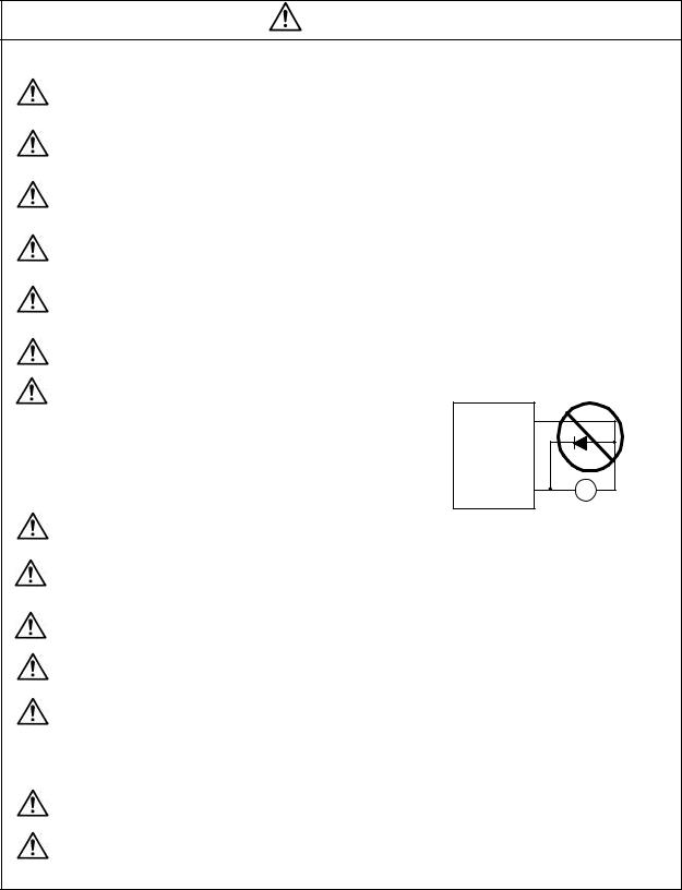
When using an inductive load such as a relay, always connect a diode as a noise measure parallel to the load.
When using a capacitance load such as a lamp, always connect a protective resistor as a noise measure serial to the load.
Do not reverse the direction of a diode which
connect to a DC relay for the control output
signals to suppress a surge.
Connecting it backwards could cause the drive
unit to malfunction so that signals are not output, and emergency stop and other safety circuits are inoperable.
Servo drive unit
|
COM |
|
(24VDC) |
|
|
Control |
output |
RA |
sig nal |
|
|
|
|
|
Do not connect/disconnect the cables connected between the units while the power is ON.
Securely tighten the cable connector fixing screw or fixing mechanism. An insecure fixing could cause the cable to fall off while the power is ON.
When using a shielded cable instructed in the connection manual, always ground the cable with a cable clamp, etc.
Always separate the signals wires from the power supply line and power line.
Use wires and cables that have a wire diameter, heat resistance and flexibility that conforms to the system.
(3) Trial operation and adjustment
Check and adjust each program and parameter before starting operation. Failure to do so could lead to unforeseen operation of the machine.
Do not make remarkable adjustments and changes as the operation could become unstable.
vi
CAUTION
(4) Usage methods
Install an external emergency stop circuit so that the operation can be stopped and power shut off immediately.
Turn the power OFF immediately if smoke, abnormal noise or odors are generated from the servomotor or servo drive unit.
Unqualified persons must not disassemble or repair the unit.
Never make modifications.
Reduce magnetic damage by installing a noise filter, etc. The electronic devices used near the servo drive unit could be affected by magnetic noise.
Use the servomotor, servo drive unit and regenerative resistor with the designated combination. Failure to do so could lead to fires or trouble.
The brake (magnetic brake) assembled into the servomotor are for holding, and must not be used for normal braking.
There may be cases when holding is not possible due to the magnetic brake's life or the machine construction (when ball screw and servomotor are coupled via a timing belt, etc.). Install a stop device to ensure safety on the machine side.
After changing the programs/parameters or after maintenance and inspection, always test the operation before starting actual operation.
Do not enter the movable range of the machine during automatic operation. Never place body parts near or touch the spindle during rotation.
Follow the power supply specification conditions given in the separate specifications manual for the power (input voltage, input frequency, tolerable sudden power failure time, etc.).
In the following explanations on bits, set all bits not used, including blank bits, to "0".
When the breaker is shared for multiple power supply units, if a short-circuit fault occurs in the unit with the smallest capacity, the breaker may not function. This is dangerous, so do not share the breaker.
Please do not use a dynamic brake as a usual slowdown stop. When continuation operation is carried out, the brake resistance for dynamic may be damaged.
(5) Troubleshooting
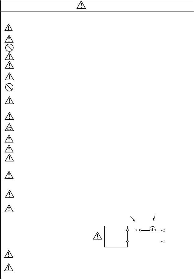
If a hazardous situation is predicted during power failure or product trouble, use a servomotor with magnetic brakes or install an external brake mechanism.
Use a double circuit configuration that allows the operation circuit for the magnetic brakes to be operated even by the external emergency stop signal.
Shut off with the servomotor |
Shut off with NC brake |
||||||
control PLC output. |
|||||||
brake control output. |
|
|
|
||||
|
|
|
|
||||
|
Servomotor |
MBR |
EMG |
||||
|
|
|
|
|
|
|
|
Magnetic 24VDC brake
Always turn the input power OFF when an alarm occurs.
Never go near the machine after restoring the power after a power failure, as the machine could start suddenly. (Design the machine so that personal safety can be ensured even if the machine starts suddenly.)
vii
CAUTION
(6) Maintenance, inspection and part replacement
Always backup the servo drive unit programs and parameters before starting maintenance or inspections.
The capacity of the electrolytic capacitor will drop due to deterioration. To prevent secondary damage due to failures, replacing this part every five years when used under a normal environment is recommended. Contact the Service Center or Service Station for replacement.
Do not perform a megger test (insulation resistance measurement) during inspections.
If the battery low warning is issued, back up the machining programs, tool data and parameters with an input/output unit, and then replace the battery.
Do not short circuit, charge, overheat, incinerate or disassemble the battery.
(7) Disposal
Treat this unit as general industrial waste.
If the heat radiating fins are protruding on the back face of the MDS Series, substitute Freon is used. Do not dispose of this type of unit as general industrial waste. Always contact the Service Station or Service Center for disposal.
Do not disassemble the servomotor or servo drive unit.
Dispose of the battery according to local laws.
(8) General precautions
The drawings given in this Specifications and Maintenance Instruction Manual show the covers and
safety partitions, etc., removed to provide a clearer explanation. Always return the covers or partitions to their respective places before starting operation, and always follow the instructions given in this manual.
viii
Compliance to European EC Directives
1. European EC Directives
In the EU Community, the attachment of a CE mark (CE marking) is mandatory to indicate that the basic safety conditions of the Machine Directives (issued Jan. 1995), EMC Directives (issued Jan. 1996) and the Low-voltage Directives (issued Jan. 1997) are satisfied. The machines and devices in which the servo and spindle drive are assembled are the targets for CE marking.
(1)Compliance to EMC Directives
The servo and spindle drive are components designed to be used in combination with a machine or device. These are not directly targeted by the Directives, but a CE mark must be attached to machines and devices in which these components are assembled. "Appendix 2", which explains the unit installation and control panel manufacturing method, etc., has been prepared to make compliance to the EMC Directives easier.
(2)Compliance to Low-voltage Directives
The MDS -C1 Series units are targeted for the Low-voltage Directives. An excerpt of the precautions given in this specification is given below. Please read this section thoroughly before starting use.
A Self-Declaration Document has been prepared for the EMC Directives and Low-voltage Directives. Contact Mitsubishi or your dealer when required.
2.Cautions for EC Directive compliance
Use the Low-voltage Directive compatible parts for the servo/spindle drive and servo/spindle motor. In addition to the items described in this instruction manual, observe the items described below.
(1) Configuration
|
|
Control panel |
|
|
|
Servo/spindle drive |
|
Isolating |
|
Electromagnetic |
|
Circuit breaker |
contactor |
Motor |
|
transformer |
AC reactor |
||
|
|
||
|
CB |
MC |
M |
Use a type B breaker
(Note) Type A ... AC and pulse detection possible Type B ... Both AC and DC detection possible
(2)Environment
Use the units within an Overvoltage Protection Category III and Pollution Class of 2 or less environment as stipulated in IEC60664.
(a)To attain the Overvoltage Category II, insert an EN or IEC Standard compliant star-connection insulated transformer in the power supply unit input.
(b)To attain a Pollution Class of 2, install the servo/spindle drive unit in a control panel having a structure (IP54 or higher) in which water, oil, carbon or dust cannot enter.
Drive unit
|
During |
Storage |
During |
|
|
operation |
transportation |
||
|
|
|||
Ambient |
0°C to 55°C |
–15°C to |
–15°C to 70°C |
|
temperature |
70°C |
|||
|
|
|||
Humidity |
90%RH or |
90%RH or |
90%RH or less |
|
less |
less |
|||
|
|
|||
|
|
|
|
|
Altitude |
1000m or |
1000m or |
10000m or less |
|
less |
less |
|||
|
|
|||
|
|
|
|
Motor
|
During |
Storage |
During |
|
|
operation |
transportation |
||
|
|
|||
Ambient |
0°C to 40°C |
–15°C to |
–15°C to 70°C |
|
temperature |
70°C |
|||
|
|
|||
Humidity |
80%RH or |
90%RH or |
90%RH or less |
|
less |
less |
|||
|
|
|||
|
|
|
|
|
Altitude |
1000m or |
1000m or |
10000m or less |
|
less |
less |
|||
|
|
|||
|
|
|
|
ix
(3)Power supply
(a)Use the servo/spindle drive unit under the Overvoltage Category III conditions stipulated in IEC60664.
(b)Do not omit the circuit breaker and electromagnetic contactor.
(4)Installation
(a)To prevent electric shocks, always connect the servo/spindle drive unit protective earth (PE) terminal (terminal with  mark) to the protective earth (PE) on the control panel. (Always ground even when using an earth leakage breaker.)
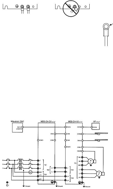
(b)When connecting the earthing wire to the protective earth (PE) terminal, do not tighten the wire terminals together. Always connect one wire to one terminal.
PE terminal |
PE terminal |
(5)Wiring
(a)Always use crimp terminals with insulation tubes so that the wires connected to the drive unit terminal block do not contact the neighboring terminals.
(b)Use a tin-plated crimp terminal that does not contain zinc for connecting the earthing wire. When tightening the screw, take care not to crush the screw threads.
(c)Refer to EN60204-1 when selecting the wire size. (Refer to section "8.5 Selection of wire size" for details.)
–Ambient temperature: 40°C max.
–Wire sheath: Cable installed on walls without ducts or conduits
–The control panel and duct wiring must be 3m or less.
If the conditions differ, refer to Table 5 in EN60204-1 Appendix C.
Crimp terminal

 Insulation tube
 Wire
Wire
(6)Peripheral devices and options
(a)Use EN/IEC Standards compliant parts for the circuit breaker and electromagnetic contactor.
(7)Miscellaneous
(a)Refer to "Appendix 2 EMC INSTALLATION GUIDELINES" for methods on complying with the EMC Directives.
(b)When using in Europe, earth the device according to each country's requirements.
(c)The control circuit connector (¡) is safety separated from the main circuit ( ).
).
MDS-CH-CV-[ ] |
|
MDS-CH-V2-[ ] |
|
|
|
|
BT-[ ] |
External emergency stop input
achine end etector
achine end
etector
External brake output contact
Electro-
AC reactor magnetic
Circuit breaker B-AL[ ] [ ] K contactor
Motor end detector
Motor end detector
Main circuit Control circuit
x

Instruction Manual for Compliance with UL/c-UL Standard
The instruction of UL/c-UL listed products is described in this manual.
The descriptions of this manual are conditions to meet the UL/c-UL standard for the UL/c-UL listed products. To obtain the best performance, be sure to read this manual carefully before use.
To ensure proper use, be sure to read specification manual, connection manual and maintenance manual carefully for each product before use.
1. UL/c-UL listed products
[CNC system]
Unit name |
Unit part number |
|
|
|
|
NC control unit |
FCU6-MU [*1]-[*2], FCU6-MA [*1]-[*2] |
Display unit |
FCU6-DU [*39][*40], FCU6-YZ [*39][*40], FCUA-LD [*41], FCUA-CT [*41], FCUA-CR [*41], |
Keyboard unit |
FCU6-YZ [*39][*40], FCU6-TZ [*39][*40], FCU6-KB0 [*42], FCUA-KB [*42] |
|
|
Base I/O unit |
FCU6-DX [*3], HR377, HR378, HR353 |
|
|
Remote I/O unit |
FCUA-DX [*4] |
|
|
I/O module |
HR357, HR371, QY231 |
|
|
[AC servo/spindle system]
Unit name |
Unit part number |
|
|
|
|
|
|
|
Power supply unit |
MDS-B-CVE- [*5], MDS-C1-CV-[*5] |
|
Servo drive unit |
MDS-B-V1- [*6], MDS-B-V14- [*6], MDS-C1-V1- [*6], MDS-B-V2- [*7], MDS-B-V24- [*7], |
|
MDS-C1-V2- [*7], MDS-B-SVJ2- [*8] |
||
|
||
|
|
|
Spindle drive unit |
MDS-B-SP [*38]-[*9], MDS-C1-SP [*38]-[*9] |
|
|
|
|
Option unit |
MDS-B-PJEX |
|
|
|
|
Battery unit |
FCU6-BT4D1 |
|
|
|
|
|
HA-FF [*10][*11][*12][*13][*14][*15][*16][*17][*18][*19] |
|
|
HC-MF [*10][*11][*12][*13][*14][*15][*16][*17][*18][*19] |
|
Servo motor |
HC-SF [*10][*11][*12][*13][*14][*15][*16][*17][*18][*19] |
|
HC-RF [*10][*11][*12][*13][*14][*15][*16][*17][*18][*19] |
||
|
HC-MF [*10][*11][*12][*13][*14][*15][*16][*17][*18][*19] |
|
|
HC-RF [*10][*11][*12][*13][*14][*15][*16][*17][*18][*19] |
|
|
HC [*20][*11][*21][*14][*22]-[*23][*24] |
|
|
|
|
Spindle Motor |
SJ [*25][*26][*27]-[*28][*29][*30][*31]-[*32] |
|
SJ [*33][*26][*28][*34][*35][*36][*37][*31] |
||
|
||
|
|
Suffixes listed below may be attached to the above part numbers at portions marked with [*]. For details regarding specifications, see the specification manuals.
[*1] |
011, 013, 021, 031, 032, 515, 516, 517, 535, 536 |
|
|
[*2] |
12, 23 |
|
|
[*3] |
210, 211, 220, 221, 310, 311, 320, 321, 330, 331, 340, 341, 350, 351, 410, 411, 420, 421, 430, 431, 440, |
||
|
441, 450, 451 |
|
|
[*4] |
100, 101, 110, 111, 120, 121, 130, 131, 140, 141 |
|
|
[*5] |
37, 55, 75, 110, 150, 185, 220, 260, 300, 370, (450, 550: Only B) |
|
|
[*6] |
01, 03, 05, 10, 20, 35, 45S, 45, 70, 90, 110, 150 |
|
|
[*7] |
0101, 0301, 0303, 0501, 0503, 0505, 1003, 1005, 1010, 2010, 2020, 3510S, 3510, 3520S, 3520, 3535, 4520, |
||
|
4535, 4545, 7035, 7045, 7070S, 7070 |
|
|
[*8] |
01, 03, 04, 06, 07, 10, 20 |
|
|
[*9] |
04, 075, 15, 22, 37, 55, 75, 110, 150, 185, 220, 260, 300, 370, (450,550:Only MDS-B Series) |
||
[*10] |
05, 1, 2, 3, 4, 5, 6, 7, 8, 10, 12, 15, 20, 30, 35 |
|
|
[*11] |
1, 2, 3 |
[*12] None, C |
[*13] None, P, N, I, E |
[*14] |
None, B |
[*15] None, Gn, GnH (n = serial number) |
|
[*16] |
None, K, D, X, T |
[*17] None, Wn (n = serial number) |
[*18] None, UL, UE |
[*19] |
None, Sn (n = serial number) |
[*20] 5, 10, 15, 20, 35, 45, 70 |
[*21] None, R |
[*22] |
S, T |
[*23] E, A |
[*24] 1, 2, 33, 42, 51 |
[*25] |
NL, PF, PL, V, VL |
[*26] None, K |
[*27] None, S |
[*28] |
Two digits decimal two digits |
[*29] 01 - 99 |
[*30] None, F, G, Y, Z |
[*31] |
None, M |
[*32] None, S01 - S99 |
[*33] None, N, P |
[*34] |
A, B, L, M, N, X |
[*35] None, 1 - 9, A - F |
[*36] None, D, H, P, Z |
[*37] |
None, B, C, F, G, R |
[*38] None, H, M, X, HX, MX |
[*39] T, C, N |
[*40] |
31, 32, 33, 34, 35, 36 |
[*41] 10, 100, 120 |
[*42] 05, 06, 10, 13, 14, 20, 30 |
xi
2. Operation surrounding air ambient temperature
The recognized operation ambient temperature of each units are as shown in the table below. The recognized operation ambient temperatures are the same as an original product specification for all of the units.
Classification |
Unit name |
Operation ambient temperature |
|
|
|
|
|
|
NC control unit |
0~55°C |
|
CNC system |
Base I/O unit |
0~55°C |
|
|
Remote I/O unit |
0~55°C |
|
|
I/O module |
0~55°C |
|
|
Power supply unit |
0~55°C |
|
AC servo/spindle |
Servo drive unit |
0~55°C |
|
Spindle drive unit |
0~55°C |
||
system |
|||
Option unit, Battery unit |
0~55°C |
||
|
|||
|
Servo motor, Spindle Motor |
0~40°C |
3. Notes for CNC system
3.1 Selection of external power supply unit
An UL recognized 24Vdc output power supply unit should be used to CNC system.
The "PD25" power supply unit provided by Mitsubishi will be changed to UL recognized product since September 2000.
4. Notes for AC servo/spindle system
4.1 General Precaution
It takes 10 minutes to discharge the bus capacitor.
When starting wiring or inspection, shut the power off and wait for more than 15 minutes to avoid a hazard of electrical shock.
4.2 Installation
MDS-B/C1 Series have been approved as the products, which have been installed in the electrical enclosure. The minimum enclosure size is based on 150 percent of each MDS-B/C1 unit combination. And also, design the enclosure so that the ambient temperature in the enclosure is 55°C (131°F) or less, refer to the manual book (chapter -section3,7).
4.3 Short-circuit ratings
Suitable for use in a circuit capable of delivering, it is not more than 5kA rms symmetrical amperes.
4.4 Peripheral devices
To comply with UL/c-UL Standard, use the peripheral devices, which conform to the corresponding standard.
- Circuit Breaker, Fuses, Magnetic Contactor and AC Reactor
Applicable power |
Circuit Breaker |
Fuse |
Magnetic contactor |
|
AC Reactor |
|
supply unit |
Class K5 |
(AC3) |
BKO-NC6851- |
|||
|
||||||
MDS-B-CVE-37 |
NF50 40A |
70A |
S-N25 |
H11 |
(B-AL-7.5K) |
|
MDS-C1-CV-37 |
||||||
|
|
|
|
|
||
MDS-B-CVE-55 |
NF50 40A |
100A |
S-N25 |
H11 |
(B-AL-7.5K) |
|
MDS-C1-CV-55 |
||||||
|
|
|
|
|
||
MDS-B-CVE-75 |
NF50 40A |
100A |
S-N25 |
H11 |
(B-AL-7.5K) |
|
MDS-C1-CV-75 |
||||||
|
|
|
|
|
||
MDS-B-CVE-110 |
NF50 50A |
100A |
S-N35 |
H12 |
(B-AL-11K) |
|
MDS-C1-CV-110 |
||||||
|
|
|
|
|
||
MDS-B-CVE-150 |
NF100 100A |
200A |
S-N50 |
H13 |
(B-AL-18.5K) |
|
MDS-C1-CV-150 |
||||||
|
|
|
|
|
||
MDS-B-CVE-185 |
NF100 100A |
200A |
S-N50 |
H13 |
(B-AL-18.5K) |
|
MDS-C1-CV-185 |
||||||
|
|
|
|
|
||
MDS-B-CVE-220 |
NF225 150A |
200A |
S-N80 |
H14 |
(B-AL-30K) |
|
MDS-C1-CV-220 |
||||||
|
|
|
|
|
||
MDS-B-CVE-260 |
NF225 150A |
300A |
S-N80 |
H14 |
(B-AL-30K) |
|
MDS-C1-CV-260 |
||||||
|
|
|
|
|
||
MDS-B-CVE-300 |
NF225 150A |
300A |
S-N80 |
H14 |
(B-AL-30K) |
|
MDS-C1-CV-300 |
||||||
|
|
|
|
|
||
MDS-B-CVE-370 |
NF225 175A |
300A |
S-N150 |
H15 |
(B-AL-37K) |
|
MDS-C1-CV-370 |
||||||
|
|
|
|
|
||
|
|
|
|
|
|
|
MDS-B-CVE-450 |
NF225 200A |
|
S-N150 |
H16 |
(B-AL-45K) |
|
MDS-B-CVE-550 |
NF400 300A |
|
S-N180 |
H17 |
(B-AL-55K) |
|
xii

- Circuit Breaker for of spindle motor Fan
Select the Circuit Breaker by doubling the spindle motor fan rated.
A rush current that is approximately double the rated current will flow, when the fan is started
<Notice>
–For installation in United States, branch circuit protection must be provided, in accordance with the National Electrical Code and any applicable local codes.
–For installation in Canada, branch circuit protection must be provided, in accordance with the
Canadian Electrical Code and any applicable provincial codes.
4.5 Flange of servomotor
Mount the servomotor on a flange, which has the following size or produces an equivalent or higher heat dissipation effect:
Flange size |
|
|
Servo Motor |
|
|
|
(mm) |
|
|
|
|
|
|
HCo |
HC-RFo |
HC-MFo |
HA-FFo |
HC-SFo |
||
|
||||||
150×150×6 |
--- |
--- |
Under 100 W |
Under 100 W |
--- |
|
|
|
|
|
|
|
|
250×250×6 |
--- |
--- |
200 W |
200,300 W |
--- |
|
250×250×12 |
0.5~1.5 kW |
1.0~2.0 kW |
400 W |
400,600 W |
0.5~1.5 kW |
|
|
|
|
|
|
|
|
300×300×12 |
--- |
--- |
750 W |
--- |
--- |
|
300×300×20 |
2.0~7.0 kW |
--- |
--- |
--- |
2.0~7.0 kW |
4.6 Motor Over Load Protection
Servo drive unit MDS-B -V1/2/14/24 Series and MDS -C1-V1/2 series and spindle drive unit MDS-B -SP and MDS-C1-SP series have each solid-state motor over load protection.
When adjusting the level of motor over load, set the parameter as follows.
4.6.1 MDS-B-V1/2/14/24, MDS -C1-V1/2 Series
Parameter |
Parameter |
Parameter |
Setting |
Standard |
Setting |
No. |
Abbr. |
Name |
Procedure |
Setting Value |
Range |
|
|
|
|
|
|
SV021 |
OLT |
Overload |
Set the time constant for overload |
60s |
1~300s |
|
|
Time constant |
detection. (Unit: 1 second.) |
|
|
|
|
|
|
|
|
SV022 |
OLL |
Overload |
Set the overload current detection level |
150% |
1~500% |
|
|
Detection level |
with a percentage (%) of the stall |
|
|
|
|
|
rating. |
|
|
|
|
|
|
|
|
4.6.2 MDS-B-SP, MDS-C1-SP Series
Parameter |
Parameter |
Parameter |
Setting |
Standard |
Setting |
No. |
Abbr. |
Name |
Procedure |
Setting Value |
Range |
|
|
|
|
|
|
SP063 |
OLT |
Overload |
Set the time constant for overload |
60s |
0~1000s |
|
|
Time constant |
detection. (Unit: 1 second.) |
|
|
|
|
|
|
|
|
SP064 |
OLL |
Overload |
Set the overload current detection level |
110% |
1~200% |
|
|
Detection level |
with a percentage (%) of the rating. |
|
|
|
|
|
|
|
|
4.7 Field Wiring Reference Table for Input and Output
Use the UL-approved Round Crimping Terminals to wire the input and output terminals of MDS-B Series.
Crimp the terminals with the crimping tool recommended by the terminal manufacturer.
Following described crimping terminals and tools type are examples of Japan Solderless Terminal Mfg. Co., Ltd.
xiii

4.7.1 Power Supply Unit (MDS-B-CVE, MDS-C1-CV Series)
|
Capacity [kW] |
3.7~7.5 |
11.0~18.5 |
22.0~37.0 |
45.0 |
55.0 |
|
|
|
P, N |
M6 |
M6 |
M6 |
M6, M10 |
|
|
|
(L+, L-) |
|||||
|
|
|
|
|
|
|
|
|
|
Screw Torque |
44.3/5.0 |
49.6/5.6 |
49.6/5.6 |
49.6/5.6, 177/20 |
|
|
|
[lb in/ N m] |
|||||
|
|
|
|
|
|
|
|
Terminal |
|
L11, L21, MC1 |
M4 |
M4 |
M4 |
M4 |
M4 |
|
(R0, S0) |
||||||
Screw |
|
|
|
|
|
|
|
|
Screw Torque |
|
|
|
|
|
|
Size |
|
17.4/2.0 |
14.2/1.6 |
14.2/1.6 |
14.2/1.6 |
14.6/1.6 |
|
|
[lb in/ N m] |
||||||
|
|
|
|
|
|
|
|
|
|
L1, L2, L3 |
M4 |
M5 |
M8 |
M8 |
M10 |
|
|
Screw Torque |
14.6/1.6 |
29.8/3.37 |
117.2/13.2 |
117.2/13.2 |
177/20 |
|
|
[lb in/ N m] |
|||||
|
|
|
|
|
|
|
|
P, N (L+, L-)
Capacity [kW] |
3.7, 5.5 |
|
7.5 |
11.0 |
15.0 |
|
18.5, 22.0 |
Wire Size (AWG) |
#10/60°C |
|
#8/60°C |
#4/60°C |
#4/60°C |
|
#3/60°C |
/Temp Rating Note 1 |
#12/75°C |
|
#10/75°C |
#8/75°C |
#4/75°C |
|
#4/75°C |
|
|
|
|
|
|
|
|
Crimping Terminals Type |
R5.5-6 |
|
R8-6 |
R22-6 |
|
R22-6 |
|
|
R5.5-6 |
R8-6 |
|
||||
|
|
|
|
|
|
||
Crimping Tools Type |
YHT-2210 |
YHT-8S |
YPT-60 |
|
YPT-60 |
||
YHT-2210 |
YHT-8S |
|
|||||
|
|
|
|
|
|
||
|
|
|
|
|
|
|
|
Capacity [kW] |
26.0 |
|
30.0 |
37.0 |
45.0 |
|
55.0 |
Wire Size (AWG) |
#1/60°C |
|
#1/75°C |
#1/0/75°C |
The bus bar is attached to |
||
/Temp Rating Note 1 |
#3/75°C |
|
the product. |
||||
|
|
|
|||||
|
|
|
|
|
|
|
|
Crimping Terminals Type |
38-S6 |
|
38-S6 |
L330T |
|
|
|
R22-6 |
|
459-12 |
|
|
|
||
|
|
|
|
|
|
||
Crimping Tools Type |
|
YPT-60 |
YET300 |
|
|
|
|
|
YF-1 |
|
|
|
|||
|
|
|
|
|
|
|
|
|
|
|
|
|
|
|
|
L11, L21 (R0, S0), MC1
Capacity [kW] |
3.7~55.0 |
Wire Size (AWG) |
#14/ 60°C |
/Temp Rating Note 1 |
#14/ 75°C |
Crimping Terminals Type |
V2-4 |
Crimping Tools Type |
YNT-1614 |
L1, L2, L3
Capacity [kW] |
3.7 |
5.5 |
7.5 |
11.0 |
|
15.0 |
18.5 |
Wire Size (AWG) |
#10/60°C |
#10/60°C |
#10/75°C |
#4/60°C |
|
#3/60°C |
#3/75°C |
/Temp Rating Note 1 |
#12/75°C |
#10/75°C |
#4/75°C |
|
#4/75°C |
||
|
|
|
|||||
|
|
|
|
||||
Crimping Terminals Type |
|
5.5-S4 |
|
|
L300T 459-23 |
|
|
Crimping Tools Type |
|
YHT-2210 |
|
|
|
YPT-60 |
|
Earth Wire Size |
#10/60°C |
#10/60°C |
#10/75°C |
#4/60°C |
|
#3/60°C |
#3/75°C |
(AWG) |
#10/75°C |
#10/75°C |
#4/75°C |
|
#4/75°C |
||
|
|
|
|||||
|
|
|
|
||||
|
|
|
|
|
|
|
|
Capacity [kW] |
22.0 |
26.0 |
30.0 |
37.0 |
|
45.0 |
55.0 |
Wire Size (AWG) |
#1/60°C |
#1/0/60°C |
#1/75°C |
1/0/75°C |
|
#2/0 |
#3/0 |
/Temp Rating Note 1 |
#2/75°C |
#1/75°C |
|
/75°C |
/75°C |
||
|
|
|
|||||
|
|
L330T |
|
L330T |
|
|
|
Crimping Terminals Type |
38-S8 |
459-12 |
38-S8 |
|
70-8 |
R80-10 |
|
459-12 |
|
||||||
|
|
38-S8 |
|
|
|
|
|
|
|
|
|
|
|
|
|
|
|
YET300 |
|
YET300 |
|
|
|
Crimping Tools Type |
YPT-60 |
YF-1 |
YPT-60 |
|
YTP-150 |
||
YF-1 |
|
||||||
|
|
YPT-60 |
|
|
|
|
|
|
|
|
|
|
|
|
|
Earth Wire Size |
#3/60°C |
#1/60°C |
#3/75°C |
1/75°C |
|
#1/75°C |
#1/0/75°C |
(AWG) |
#3/75°C |
#3/75°C |
|
||||
|
|
|
|
|
|||
xiv

4.7.2 Servo Drive Unit (MDS-B-V1/2/14/24, MDS-C1-V1/2 Series)
|
|
Axis |
|
1-axis (V1, V14) |
|
2-axes (V2, V24) |
|
|
Capacity [kW] |
0.1 3.5 |
4.5 9.0 |
|
11.0, |
0.1+0.1 7.0+7.0 |
|
|
|
15.0 |
|||||
|
|
|
|
|
|
|
|
|
|
|
|
|
|
|
|
|
|
P, N |
M6 |
M6 |
|
M6 |
M6 |
|
|
(L+, L-) |
|
||||
|
|
|
|
|
|
|
|
|
|
Screw Torque |
44.3 |
44.3 |
|
44.3 |
44.3 |
|
|
[lb in/ N m] |
/5.0 |
/5.0 |
|
/5.0 |
/5.0 |
|
|
|
|
|
|
|
|
Terminal |
L11, L21 |
M4 |
M4 |
|
M4 |
M4 |
|
(R0, S0) |
|
||||||
Screw |
|
|
|
|
|
|
|
|
Screw Torque |
17.4 |
17.4 |
|
17.4 |
17.4 |
|
Size |
|
|
|||||
|
[lb in/ N m] |
/2.0 |
/2.0 |
|
/2.0 |
/2.0 |
|
|
|
|
|||||
|
|
|
|
|
|
|
|
|
|
U, V, W |
M4 |
M5 |
|
M8 |
M4 |
|
|
Screw Torque |
14.6 |
28.6 |
|
117.2 |
14.6 |
|
|
[lb in/ N m] |
/1.6 |
/3.2 |
|
/13.2 |
/1.6 |
P, N (L+, L-)
Wire size depends on the Power Supply Unit (MDS -B-CVE, MDS-C1-CV Series).
L11, L21 (R0, S0)
Capacity [kW] |
0.1 15.0 |
|
|
Wire Size (AWG) |
#14/ 60°C |
/Temp Rating Note 1 |
#14/ 75°C |
|
|
Crimping Terminals Type |
V2-4 |
|
|
Crimping Tools Type |
YNT-1614 |
|
|
U, V, W
Capacity [kW] |
0.1 1.0 |
|
2.0 |
3.5 |
|
4.5 |
|
|
|
|
|
|
|
Wire Size (AWG) |
#14/60°C |
|
#10/60°C |
#8/60°C |
|
#8/60°C |
/Temp Rating Note 1 |
#14/75°C |
|
#14/75°C |
#10/75°C |
|
#10/75°C |
|
|
|
||||
|
|
|
|
|
|
|
|
|
|
R5.5-4 |
8-4 |
|
R8-5 |
|
|
|
|
(8-4) |
||
Crimping Terminals Type |
R2-4 |
|
|
|
|
|
|
|
|
|
R5.5-5 |
||
|
|
|
T2-4 |
R5.5-4 |
|
|
|
|
|
|
(R5.5-4) |
||
|
|
|
|
|
|
|
Crimping Tools Type |
YHT-2210 |
|
|
YHT-8S |
||
|
|
YHT-2210 |
||||
|
|
|
|
|
||
Earth wire Size |
#14/60°C |
|
#10/60°C |
#8/60°C |
|
#8/60°C |
(AWG) |
#14/75°C |
|
#12/75°C |
#10/75°C |
|
#10/75°C |
|
|
|
|
|
|
|
|
|
|
|
|
|
|
Capacity [kW] |
7.0 |
|
9.0 |
11.0 |
|
15.0 |
|
|
|
|
|
|
|
Wire Size (AWG) |
#8/60°C |
|
#8/60°C |
#4/60°C |
|
#2/60°C |
/Temp Rating Note 1 |
#8/75°C |
|
#8/75°C |
#4/75°C |
|
#3/75°C |
|
|
|
|
|
|
|
Crimping Terminals Type |
R8-5 |
|
R8-5 |
R22-8 |
|
R38-8 |
(8-4) |
|
|
||||
|
|
|
|
|
|
|
|
|
|
|
|
|
|
Crimping Tools Type |
YHT-8S |
|
|
YPT-60 |
||
|
|
|
|
|
|
|
Earth Wire Size |
#8/60°C |
|
#8/60°C |
#4/60°C |
|
#3/60°C |
(AWG) |
#8/75°C |
|
#8/75°C |
#4/75°C |
|
#3/75°C |
|
|
|
||||
xv

4.7.3 Spindle Drive Unit (MDS-B-SP, MDS-C1-SP Series)
|
Capacity [kW] |
0.4~3.7 |
5.5~18.5 |
22.0~30.0 |
37.0 |
45.0/55.0 |
||
|
|
P, N |
M6 |
M6 |
M6 |
M10 |
M10 |
|
|
|
(L+, L-) |
||||||
|
|
|
|
|
|
|
||
|
|
Screw Torque |
44.3/5.0 |
44.3/5.0 |
44.3/5.0 |
234.3/26.5 |
177/20 |
|
|
|
[lb in/ N m] |
||||||
|
|
|
|
|
|
|
||
|
|
|
|
|
|
|
|
|
Terminal |
L11, L21 |
M4 |
M4 |
M4 |
M4 |
M4 |
||
(R0, S0) |
||||||||
Screw |
|
|
|
|
|
|
||
|
Screw Torque |
|
|
|
|
|
||
Size |
|
17.4/2.0 |
17.4/2.0 |
17.4/2.0 |
17.4/2.0 |
17.2/2.0 |
||
|
|
[lb in/ N m] |
||||||
|
|
|
|
|
|
|
||
|
|
U, V, W |
M4 |
M5 |
M8 |
M8 |
M10 |
|
|
|
Screw Torque |
14.6/1.6 |
28.6/3.2 |
117.2/13.2 |
88.5/10.0 |
177/20 |
|
|
|
[lb in/ N m] |
||||||
|
|
|
|
|
|
|
||
P, N (L+, L-)
Wire size depends on the Power Supply Unit (MDS-B -CVE, MDS-C1-CV Series).
L11, L21 (R0, S0)
Capacity [kW] |
0.4~55.0 |
Wire Size (AWG) |
#14/60°C |
/Temp Rating Note 1 |
#14/75°C |
|
|
Crimping Terminals Type |
V2-4 |
Crimping Tools Type |
YNT-1614 |
U, V, W
Capacity [kW] |
0.4, 0.75 |
1.5 |
|
2.2, 3.7 |
5.5 |
7.5 |
11.0 |
15.0 |
|
Wire Size (AWG) |
#14 /60°C |
#10/60°C |
#10/60°C |
#8/60°C |
#8/60°C |
#4/60°C |
|||
/Temp Rating Note 1 |
#14 /75°C |
#14/75°C |
#12/75°C |
#10/75°C |
#8/75°C |
#4/75°C |
|||
Crimping Terminals |
R2-4 |
5.5-S4 |
|
R5.5-4 |
R5.5-5 |
R8-5 |
R8-5 |
L330T |
|
Type |
|
|
|
|
459-23 |
||||
R2-4 |
|
R5.5-5 |
|||||||
|
|
|
|
||||||
Crimping Tools Type |
|
YHT-2210 |
|
YHT-8S |
YHT-8S |
YPT-60 |
|||
|
|
YHT-2210 |
|||||||
|
|
|
|
|
|
|
|
||
|
|
|
|
|
|
|
|||
Earth Wire Size |
#14 /60°C |
#11/60°C |
#10/60°C |
#8/60°C |
#8/60°C |
#4 /60°C |
|||
(AWG) |
#14 /75°C |
#14/75°C |
#10/75°C |
#10/75°C |
#8/75°C |
#4 /75°C |
|||
|
|
|
|
|
|
|
|
|
|
Capacity [kW] |
18.5 |
22.0 |
|
26.0 |
30.0 |
37.0 |
45.0 |
55.0 |
|
Wire Size (AWG) |
#3/60°C |
#2/60°C |
|
#1/60°C |
#1/75°C |
#1/0/75°C |
#2/0 |
#4/0 |
|
/Temp Rating Note 1 |
#4/75°C |
#3/75°C |
|
#2/75°C |
75°C |
/75°C |
|||
|
|
|
|||||||
Crimping Terminals |
22-S6 |
|
|
R38-8 |
|
R60-8 |
70-10 |
R100-10 |
|
L330T |
|
|
|
||||||
Type |
|
|
|
||||||
|
|
|
|
|
|
|
|||
|
459-23 |
|
|
|
|
|
|
|
|
|
|
|
|
|
|
|
|
|
|
Crimping Tools Type |
|
YPT-60 |
|
YET300 |
YPT-150 |
||||
|
|
YF-1 |
|||||||
|
|
|
|
|
|
|
|
||
|
|
|
|
|
|
|
|||
Earth Wire Size |
#3/60°C |
#3/60°C |
#3/75°C |
#1/75°C |
#1/75°C |
#3/0 |
|||
(AWG) |
#4/75°C |
#3/75°C |
/75°C |
||||||
|
|
|
|||||||
Note 1: 60°C: Polyvinyl chloride insulated wires (IV)
75°C: Grade heat-resistant polyvinyl chloride insulated wires (HIV) Use copper wire only.
Above listed wire are for use in the electric cabinet on machine or equipment.
xvi

4.8 Spindle Drive / Motor Combinations
Following combinations are the Standard combinations
Rating Output (kW)
Of Applicable Spindle Motor
Drive Unit Note: 1 |
SJ- ( ) Series |
SJ-N Series |
|
|
SJ-V/VL Series |
||
|
SJ-NL Series |
||
|
Note: 2 |
||
|
|
||
MDS-B-SP []-04 |
|
0.2 |
|
MDS-C1-SP []-04 |
|
||
|
|
||
MDS-B-SP []-075 |
|
0.75 |
|
MDS-C1-SP []-075 |
|
||
|
|
||
MDS-B –SP []-15 |
|
1.5 |
|
MDS-C1-SP []-15 |
|
||
|
|
||
MDS-B –SP []-22 |
2.2 |
2.2 |
|
MDS-C1-SP []-22 |
|||
|
|
||
MDS-B –SP []-37 |
3.7 |
3.7 |
|
MDS-C1-SP []-37 |
|||
|
|
||
MDS-B-SP []-55 |
5.5 |
5.5 |
|
MDS-C1-SP []-55 |
|||
|
|
||
MDS-B-SP []-75 |
5.5 |
7.5 |
|
MSD-C1-SP []-75 |
7.5 |
||
|
|||
MDS-B-SP []-110 |
5.5 |
|
|
7.5 |
11 |
||
MDS-C1-SP []-110 |
|||
11 |
|
||
|
|
||
MDS-B-SP []-150 |
7.5 |
|
|
11 |
|
||
MDS-C1-SP []-150 |
|
||
15 |
|
||
|
|
||
MDS-B-SP []-185 |
11 |
|
|
15 |
|
||
MDS-C1-SP []-185 |
|
||
18.5 |
|
||
|
|
||
MDS-B-SP []-220 |
11 |
|
|
15 |
|
||
MDS-C1-SP []-220 |
18.5 |
|
|
|
22 |
|
|
|
11 |
|
|
MDS-B-SP []-260 |
15 |
|
|
18.5 |
|
||
MDS-C1-SP []-260 |
|
||
22 |
|
||
|
|
||
|
26 |
|
|
|
15 |
|
|
MDS-B-SP []-300 |
18.5 |
|
|
22 |
|
||
MDS-C1-SP []-300 |
|
||
26 |
|
||
|
|
||
|
30 |
|
|
|
15 |
|
|
|
18.5 |
|
|
MDS-B-SP [] –370 |
22 |
|
|
26 |
|
||
|
|
||
|
30 |
|
|
|
37 |
|
|
|
22 |
|
|
MDS-B-SP [] -450 |
26 |
|
|
30 |
|
||
|
37 |
|
|
|
45 |
|
|
|
30 |
|
|
MDS-B-SP [] -550 |
37 |
|
|
45 |
|
||
|
|
||
|
55 |
|
|
Note 1: [] can be H, M, X, HX, MX or none. |
|
||
Note 1: Applicable unit depends on the range of power constant of motor. Inquire of Mitsubishi about the detail of the combinations.
xvii
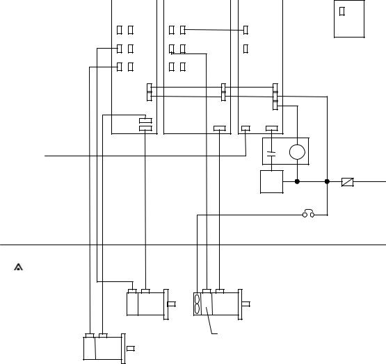
5. AC Servo/Spindle System Connection
|
|
MDS -C1 -V1/V2 Series |
|
|
|
|
|
|
MDS -C1 -CV Series |
|
||||||
|
|
MDS -B-V1/V2 Series |
MDS -C1 -SP[ H][M ][X] Series |
|
||||||||||||
|
|
MDS -B-V14/V24 Series |
MDS -B-S P (H)(M )[X] Series |
MDS -B-CVE Series |
|
|||||||||||
|
|
|
|
|
|
|
|
|
|
|
|
|
|
|
|
|
From NC |
|
|
CN1A CN1B |
CN1A CN1B |
|
|
||||||||||
|
|
|
|
|
|
|
|
|
|
|
|
|
|
|
|
|
|
|
|
|
|
|
|
|
|
|
|
|
|
|
|
|
|
Regarding the connection of NC, |
|
|
|
|
|
|
|
|
|
|
|
|
|
|||
|
CN9 CN4 |
CN9 CN4 |
CN4 |
|
||||||||||||
see the NC manual book. |
|
|
|
|
|
|
|
|
|
|
|
|
|
|
|
|
CN2L CN3L |
CN5 |
CN6 |
CN9 |
|
Battery Unit |
|
|
|
|
|
|
|
|
|
|
|
|
|
|
or |
CN2 |
CN3 |
CN7 |
CN8 |
|
|
Terminator A -TM |
|
|
|
||||
|
|
|
|
|
L+/L - |
|
|
|
|
|
|
L11/L21 |
|
|
MU/MV/MW |
|
|
|
MC1 |
|
|
|
|
|
|
|
|
|
|
|
U/V/W |
CN23 |
L1/L2/L3 |
|
LU/LV/LW |
|
|
|
|
|
|
External Emergency Stop |
|
|
|
|
MC |
|
|
|
|
|
MC |
|
|
|
|
|
|
|
|
|
Refer to specification manual |
|
|
|
|
Contactor |
Fuse or |
BNP-C3000 |
|
|
|
|
||
|
|
|
|
|
Breaker |
|
|
|
|
|
|
AC-L |
3-phase |
|
|
|
|
|
|
|
|
|
|
|
|
AC reactor |
200/220VAC |
|
|
|
|
|
|
|
|
|
|
|
|
Circuit Breaker |
|
Enclosure Side |
|
|
|
|
|
|
Machine Side |
|
|
|
|
|
|
|
Servo Motor |
Spindle Motor |
|
|||
Encoder |
|
FAN |
|
|
|
|
|
|
|
Encoder and |
|
|
|
|
Servo Motor |
|
Thermal Protection |
|
||
|
|
|
|
|
|
|
Encoder |
|
|
|
|
|
|
xviii
|
CONTENTS |
|
Chapter I MDS-C1 Series Servo/Spindle System Configuration Section |
|
|
1. Outline .................................................................................................................... |
I-2 |
|
2. Drive Section System Configuration ............................................................................... |
I-4 |
|
3. Unit Installation ............................................................................................................... |
I-12 |
|
4. Connection of Each Unit ................................................................................................. |
I-16 |
|
4.1 |
Layout of each unit ................................................................................................. |
I-17 |
4.2 |
Link bar specifications ............................................................................................ |
I-17 |
4.3 |
Unit separated layout ............................................................................................. |
I-19 |
4.4 |
Precautions for installing multiple power supply units ............................................ |
I-20 |
4.5Precautions for installing only one power supply unit for the
|
2CH communication specifications with the NC (For 2-system control).................. |
I-21 |
|
4.6 |
Connection of battery unit ...................................................................................... |
I-22 |
|
4.6.1 |
Battery unit ...................................................................................................... |
I-22 |
|
4.6.2 |
Connection...................................................................................................... |
I-22 |
|
5. Drive Section Connector and Cable Specifications ........................................................ |
I-24 |
||
5.1 |
Half pitch cable connection system ........................................................................ |
I-24 |
|
5.2 |
Cable details .......................................................................................................... |
I-26 |
|
5.2.1 |
Communication cable SH21 (semi ordered product) ..................................... |
I-26 |
|
5.2.2 |
Terminator A-TM (ordered part) .................................................................... |
I-26 |
|
5.2.3 |
Servo drive unit detector cable ...................................................................... |
I-27 |
|
5.2.4 |
Brake cable .................................................................................................... |
I-29 |
|
5.2.5 |
Communication cable SH21 connector ......................................................... |
I-30 |
|
5.2.6 |
Cannon plug for servomotor detector ............................................................ |
I-31 |
|
5.2.7 |
Cable wire ...................................................................................................... |
I-33 |
|
5.2.8 |
Cable protection tube (noise countermeasure) ............................................. |
I-34 |
|
5.2.9 |
Oil-proof type servomotor cable connectors (Recommendation 1) ............... |
I-35 |
|
5.2.10 |
Oil-proof type servomotor connectors (Recommendation 2) ......................... |
I-36 |
|
5.2.11 |
Cable clamp ................................................................................................... |
I-37 |
|
5.2.12 |
Spindle control circuit cable list ...................................................................... |
I-38 |
|
5.2.13 |
Cable assembly procedure (Excluding SH21 cable)....................................... |
I-53 |
|
6. Outline Drawing .............................................................................................................. |
I-58 |
||
6.1 |
Panel installation structure ..................................................................................... |
I-58 |
|
6.2 |
Power supply unit ................................................................................................... |
I-59 |
|
6.3 |
1-axis servo drive unit/2-axis servo drive unit/spindle servo drive unit ................... |
I-60 |
|
6.4 |
Battery unit............................................................................................................... |
I-61 |
|
6.5 |
AC reactor................................................................................................................ |
I-62 |
|
6.6 |
Dynamic brake unit.................................................................................................. |
I-63 |
|
6.7 |
Contactor ................................................................................................................ |
I-63 |
|
6.8 |
Circuit Breaker (CB)................................................................................................. |
I-63 |
|
7. Heating Value ................................................................................................................. |
I-66 |
||
8. Selection of Capacity ....................................................................................................... |
I-68 |
||
8.1 |
Selection of the power supply unit capacity............................................................. |
I-68 |
|
8.1.1 |
Selection with rated capacity (continuous rated capacity)............................... |
I-68 |
|
8.1.2 |
Selection with maximum momentary rated capacity....................................... |
I-70 |
|
8.1.3 |
Selection data.................................................................................................. |
I-70 |
|
8.1.4 |
Selection example........................................................................................... |
I-71 |
|
8.2 |
Selection of leakage breaker ................................................................................... |
I-72 |
|
8.3 |
Noise filter................................................................................................................ |
I-73 |
|
8.4 |
Selection of power supply capacity ........................................................................ |
I-75 |
|
8.5 |
Selection of wire size ............................................................................................. |
I-76 |
|
8.6 |
Selection of AC reactor, contactor and CB ............................................................ |
I-81 |
|
i
Chapter II |
MDS-C1-CV Power Regeneration Type |
Power Supply Section |
|
1. Power Regeneration Type Power Supply........................................................................ |
II-2 |
||
1.1 |
C1-CV Outline ........................................................................................................ |
II-2 |
|
1.2 |
Model configuration ................................................................................................. |
II-2 |
|
1.3 |
List of unit models and outlines................................................................................ |
II-3 |
|
1.4 |
List of specifications ............................................................................................... |
II-7 |
|
1.5 |
Hardware and parameter setting ............................................................................ |
II-9 |
|
1.6 |
Status display ......................................................................................................... |
II-10 |
|
1.6.1 |
7-segment LED display ................................................................................. |
II-10 |
|
1.6.2 |
Charge lamp .................................................................................................. |
II-10 |
|
1.7 |
List of alarms and warnings ................................................................................... |
II-11 |
|
1.8 |
Explanation of connectors and terminal block ........................................................ |
II-13 |
|
1.9 |
Power supply external emergency stop function ..................................................... |
II-14 |
|
1.10 |
Main circuit connection ........................................................................................... |
II-17 |
|
Chapter III |
MDS-C1-Vx Servo System Section |
III-2 |
|
1. Outline |
.................................................................................................................... |
||
2. Motor |
.................................................................................................................... |
III-4 |
|
2.1 |
Outline .................................................................................................................... |
III-4 |
|
2.2 |
Model configuration ................................................................................................ |
III-5 |
|
2.3 |
Main equipment list ................................................................................................ |
III-7 |
|
2.4 |
Specifications list .................................................................................................... |
III-8 |
|
2.5 |
Torque characteristics.............................................................................................. |
III-15 |
|
2.6 |
Duty drive characteristics......................................................................................... |
III-22 |
|
2.7 |
Outline dimension drawings ................................................................................... |
III-25 |
|
2.8 |
Motor connection .................................................................................................... |
III-43 |
|
2.9 |
Motors with electromagnetic brake ........................................................................ |
III-48 |
|
2.10 |
Motor vibration resistance ...................................................................................... |
III-53 |
|
2.11 |
Motor shaft strength ............................................................................................... |
III-54 |
|
2.12 |
Environmental conditions......................................................................................... |
III-56 |
|
3. Detectors |
.................................................................................................................... |
III-58 |
|
3.1 |
List of detector specifications ................................................................................. |
III-58 |
|
3.2 |
Serial pulse encoder .............................................................................................. |
III-59 |
|
3.2.1 |
Features ........................................................................................................ |
III-59 |
|
3.2.2 |
Types ............................................................................................................. |
III-59 |
|
3.2.3 |
Outline dimension drawings .......................................................................... |
III-60 |
|
3.2.4 |
Cable connection diagram ............................................................................. |
III-63 |
|
3.2.5 |
Maintenance .................................................................................................. |
III-64 |
|
3.3 |
Scale I/F unit............................................................................................................ |
III-65 |
|
3.3.1 |
Outline............................................................................................................. |
III-65 |
|
3.3.2 |
Model configuration ......................................................................................... |
III-65 |
|
3.3.3 |
List of specifications ........................................................................................ |
III-65 |
|
3.3.4 |
Unit outline dimension drawing ....................................................................... |
III-66 |
|
3.3.5 |
Description of connector.................................................................................. |
III-67 |
|
3.3.6 |
Example of scale I/F unit connection ............................................................. |
III-68 |
|
3.3.7 |
Cables ............................................................................................................. |
III-70 |
|
4. Servomotor and Detector Installation ............................................................................. |
III-72 |
||
4.1 |
Installation .............................................................................................................. |
III-72 |
|
4.2 |
Coupling with the load ............................................................................................ |
III-76 |
|
ii
5. MDS-C1-V1 Servo Drive ................................................................................................ |
III-80 |
5.1Availability of 2-system
|
(standard drive unit mode and high-gain drive unit mode)..................................... |
III-80 |
|
5.2 |
Model configuration ................................................................................................. |
III 81 |
|
5.3 |
Specifications list .................................................................................................... |
III-82 |
|
5.4 |
Connection of dynamic brake unit ........................................................................ |
III-85 |
|
5.5 |
Hardware setting .................................................................................................... |
III-87 |
|
5.6 |
Parameter settings ................................................................................................. |
III-88 |
|
5.6.1 |
Standard Parameters (Standard Drive unit).................................................... |
III-89 |
|
5.6.2 |
High-gain Parameters (High-gain Drive unit) .................................................. |
III-113 |
|
5.7 |
Alarms and Warnings ............................................................................................. |
III-138 |
|
5.8 |
Explanation of connector and terminal block ......................................................... |
III-147 |
|
5.9 |
Main circuit and brake connection .......................................................................... |
III-148 |
|
5.9.1 |
Main circuit .................................................................................................... |
III-148 |
|
5.9.2 |
Brake ............................................................................................................. |
III-150 |
|
5.10 |
Wiring system diagrams for systems ..................................................................... |
III-151 |
|
5.11 |
D/A output function ................................................................................................. |
III-154 |
|
5.11.1 |
Outline ........................................................................................................... |
III-154 |
|
5.11.2 |
Hardware specifications ................................................................................ |
III-154 |
|
5.11.3 |
Parameters .................................................................................................... |
III-154 |
|
5.11.4 |
Output data No. ............................................................................................. III-155 |
||
5.11.5 |
Setting of output magnification ...................................................................... |
III-155 |
|
5.11.6 |
Others ............................................................................................................ |
III-156 |
|
6. MDS-C1-V2 Servo Drive ................................................................................................ |
III-158 |
||
6.1 |
Model configuration ................................................................................................ |
III-158 |
|
6.2 |
Servo drive unit specifications ................................................................................ |
III-159 |
|
6.3 |
Hardware setting .................................................................................................... |
III-163 |
|
6.4 |
Status display ......................................................................................................... |
III-164 |
|
6.5 |
Explanation of terminal block and connectors ........................................................ |
III-166 |
|
6.6 |
Main circuit connection ........................................................................................... |
III-167 |
|
7. Selection of Capacity ...................................................................................................... |
III-170 |
||
7.1 |
Selection of servo system ...................................................................................... |
III-170 |
|
7.1.1 |
Types of drive systems .................................................................................. |
III-170 |
|
7.1.2 |
Selection of servomotor ................................................................................. |
III-171 |
|
7.2 |
Determining the coasting amount with emergency stop ........................................ |
III-182 |
|
Chapter IV MDS-C1-SP Spindle System Section |
IV-2 |
||
1. Outline |
.................................................................................................................... |
||
1.1 |
Features of the MDS-C1-SP spindle system ......................................................... |
IV-2 |
|
1.2 |
Precautions for use.................................................................................................. |
IV-2 |
|
1.3 |
Model configuration ................................................................................................ |
IV-3 |
|
1.4 |
Configuration .......................................................................................................... |
IV-4 |
|
1.4.1 |
Basic configuration (no added functions) ...................................................... |
IV-4 |
|
1.4.2 |
With orientation function ................................................................................ |
IV-4 |
|
1.4.3 |
High-speed synchronous tap/spindle synchronization/with |
IV-6 |
|
|
|
orientation function ........................................................................................ |
|
1.4.4 |
OSE90K+1024 encoder C-axis control/with orientation function ................... |
IV-7 |
|
1.4.5OSE90K+1024 encoder C-axis control and high-speed synchronous tap/
spindle synchronization/with orientation function .......................................... |
IV-8 |
1.4.6 MBE90K encoder C-axis control/with orientation function ............................. |
IV-9 |
1.4.7MBE90K encoder C-axis control and high-speed synchronous tap/
spindle synchronization/with orientation function .......................................... |
IV-9 |
1.4.8 MHE90K encoder C-axis control/with orientation function ............................ |
IV-10 |
1.4.9MHE90K encoder C-axis control and high-speed synchronous tap/
|
spindle synchronization/with orientation function .......................................... |
IV-10 |
1.5 |
Device-to-device connections .............................................................................. |
IV-11 |
iii
2. Specifications................................................................................................................... |
IV-14 |
||
2.1 |
AC spindle motor and controller specifications ...................................................... |
IV-14 |
|
2.2 |
Output characteristics ............................................................................................ |
IV-19 |
|
2.3 |
Outline dimension drawings ................................................................................. |
IV-22 |
|
2.3.1 |
Motor ............................................................................................................. |
IV-22 |
|
3. Status Display and Parameter Settings ........................................................................... |
IV-30 |
||
3.1 |
Status display with 7-segment LED ......................................................................... |
IV-30 |
|
3.2 |
Spindle parameters.................................................................................................. |
IV-31 |
|
3.3 |
Spindle specification parameters screen................................................................. |
IV-60 |
|
3.4 |
Spindle monitor screen............................................................................................ |
IV-64 |
|
3.5 |
Control input signals ................................................................................................ |
IV-68 |
|
3.6 |
Control output signals .............................................................................................. |
IV-71 |
|
3.7 |
Meter outputs ........................................................................................................... |
IV-74 |
|
3.8 |
Output interface....................................................................................................... |
IV-76 |
|
3.9 |
Spindle protection/warning functions ....................................................................... |
IV-77 |
|
4. Optional Specifications and Parts ................................................................................... |
IV-80 |
||
4.1 |
Orientation specifications (optional)........................................................................ |
IV-80 |
|
|
4.1.1 1-point orientation using magnetic sensor ..................................................... |
IV-80 |
|
|
4.1.2 4096-point orientation using encoder ............................................................. |
IV-88 |
|
|
4.1.3 4096-point orientation using motor built-in encoder....................................... |
IV-91 |
|
|
4.1.4 |
Operation of orientation .................................................................................. |
IV-91 |
4.2 |
Synchronous tap function (option) .......................................................................... |
IV-94 |
|
|
4.2.1 Closed type synchronous tap ......................................................................... |
IV-94 |
|
|
4.2.2 Semi-closed type synchronous tap ................................................................ |
IV-94 |
|
|
4.2.3 Operation of synchronous tap ........................................................................ |
IV-94 |
|
4.3 |
C-axis control (optional) .......................................................................................... |
IV-95 |
|
|
4.3.1 When using encoder (OSE90K+1024 BKO-NC6336H01)............................. |
IV-95 |
|
|
4.3.2 When using built-in encoder (MBE90K) ......................................................... |
IV-98 |
|
|
4.3.3 When using built-in encoder (MHE90K)......................................................... |
IV-98 |
|
4.4 |
Single parts (optionally supplied parts)................................................................... |
IV-99 |
|
|
4.4.1 |
Power step-down transformer ........................................................................ |
IV-99 |
|
4.4.2 |
Noise filter ....................................................................................................... |
IV-101 |
4.5 |
Other optional specifications ................................................................................... |
IV-103 |
|
4.6 |
Theoretical acceleration and deceleration times .................................................... |
IV-104 |
|
Chapter V |
IPM Spindle Drive System Section |
V-2 |
|
1. Outline |
.................................................................................................................... |
||
1.1 |
Outline .................................................................................................................... |
V-2 |
|
1.2 |
Features of MDS-C1-SPM Series........................................................................... |
V-2 |
|
1.3 |
Precautions for use ................................................................................................ |
V-2 |
|
2. Configuration of Drive System ........................................................................................ |
V-4 |
||
2.1 |
Basic system configuration drawing ....................................................................... |
V-4 |
|
2.2 |
Combination with power supply unit ....................................................................... |
V-4 |
|
2.3 |
List of IPM spindle drive units ............................................................................... |
V-5 |
|
3. Setting the IPM Spindle Drive Unit Parameters.............................................................. |
V-8 |
||
3.1 |
Bit selection parameters.......................................................................................... |
V-8 |
|
3.2 |
Setting the unit type, motor and power supply unit ................................................ |
V-10 |
|
3.3 |
Spindle monitor screen .......................................................................................... |
V-11 |
|
3.4 |
List of spindle protection functions and warning functions ..................................... |
V-15 |
|
i v
4. Setup Procedures ............................................................................................................ |
V-18 |
||||
4.1 |
Wiring the drive unit ................................................................................................ |
V-18 |
|||
4.2 |
Setting the parameters............................................................................................ |
V-18 |
|||
4.3 |
PLG Z-phase automatic adjustment ..................................................................... |
V-18 |
|||
4.4 |
PLG automatic adjustment of SPM unit.................................................................. |
V-19 |
|||
4.5 |
Alarms .................................................................................................................... |
V-19 |
|||
4.6 |
Handling the motor .................................................................................................. |
V-19 |
|||
|
4.6.1 |
Storage ............................................................................................................. |
V-19 |
||
|
4.6.2 |
Assembly (built-in type).................................................................................... |
V-19 |
||
5. IPM Spindle Motor Specifications .................................................................................... |
V-22 |
||||
5.1 |
IPM spindle motor specifications ............................................................................ |
V-22 |
|||
5.2 |
Motor outline drawings ............................................................................................ |
V-23 |
|||
Appendix 1 EN Standards Step-down Insulation Transformer.................................... |
AI-2 |
||||
Appendix 2 |
EMC Installation Guidelines....................................................................... |
AII-2 |
|||
1. |
Introduction................................................................................................................... |
AII-2 |
|||
2. |
EMC Instructions .......................................................................................................... |
AII-2 |
|||
3. |
EMC Measures............................................................................................................. |
AII-3 |
|||
4. |
Measures for panel structure........................................................................................ |
AII-3 |
|||
|
4.1 |
|
Measures for control box unit.......................................................................... |
AII-3 |
|
|
4.2 |
|
Measures for door........................................................................................... |
AII-4 |
|
|
4.3 |
|
Measures for operation board panel ............................................................... |
AII-4 |
|
|
4.4 |
|
Shielding of the power supply input section .................................................... |
AII-4 |
|
5. |
Measures for various cables......................................................................................... |
AII-5 |
|||
|
5.1 |
|
Measures for wiring in box .............................................................................. |
AII-5 |
|
|
5.2 |
|
Measures for shield treatment......................................................................... |
AII-5 |
|
|
5.3 |
|
Servomotor power cable ................................................................................. |
AII-6 |
|
|
5.4 |
|
Servomotor feedback cable............................................................................. |
AII-6 |
|
|
5.5 |
|
Spindle motor power cable.............................................................................. |
AII-7 |
|
|
5.6 |
|
Spindle motor feedback cable......................................................................... |
AII-7 |
|
|
5.7 |
|
Cable between control box and operation board panel................................... |
AII-7 |
|
6. |
EMC Countermeasure Parts ........................................................................................ |
AII-8 |
|||
|
6.1 |
|
Shield clamp fitting .......................................................................................... |
AII-8 |
|
|
6.2 |
|
Ferrite core...................................................................................................... |
AII-9 |
|
Appendix 3 |
Unit system.................................................................................................. |
AIII-2 |
|||
Appendix 4 Classification of Servo/Spindle Drive Unit Circuits Based on |
AIV-2 |
||||
|
|
|
|
Higher Harmonic Suppression Countermeasures Guidelines.............. |
|
Appendix 5 Explanation of Large Capacity Spindle Unit Specifications.................. |
AV-2 |
||||
1. |
Outline |
.................................................................................................................... |
AV-2 |
||
2. |
List of units ................................................................................................................... |
AV-2 |
|||
3. |
Selection of AC reactor (B-AL), contactor and CB .................................................... |
AV-2 |
|||
4. |
Outline of units ............................................................................................................. |
AV-3 |
|||
5. |
Panel cut dimension drawing....................................................................................... |
AV-4 |
|||
6. |
Detailed outline drawing .............................................................................................. |
AV-5 |
|||
7. |
Heating value ............................................................................................................... |
AV-8 |
|||
8. |
Selection of power capacity ......................................................................................... |
AV-8 |
|||
9. |
Selecting the wire size................................................................................................. |
AV-8 |
|||
10. |
Drive unit connection screw size................................................................................ |
AV-9 |
|||
11. |
Connection of each unit .............................................................................................. |
AV-9 |
|||
12. |
Restrictions ................................................................................................................. |
AV-11 |
|||
13. Parameters ................................................................................................................. |
AV-12 |
||||
14. |
Precautions ................................................................................................................. |
AV-12 |
|||
v

I. MDS-C1 Series
Servo/Spindle System Configuration
Section

1. Outline
1. Outline .................................................................................................................... |
I-2 |
I - 1

1. Outline
1. Outline
MDS-C1 Series servo and spindle system outline
The MDS-C1 Series is MELDAS drive system that has been developed totally connected the servo drive and spindle drive sections.
The MDS-C1 Series is the successor to the MDS-B Series, and has been developed to satisfy European Safety Standards. This Series has the following features.
(1)Compact and lightweight
The converters that were conventionally built in each servo and spindle drive have been integrated into one unit. The drive system volume, installation area and weight have been drastically reduced with the incorporation of high density mounted electronic parts IGBT-IPM (Intelligent Power Module) and the high performance heat radiating fin.
(2)Standardization of dimensions
The outline has been standardized to the book end type, and by unifying the height and depth dimensions, installation in control box has been made easy. Furthermore, by matching the shape with the NC unit (M500 Series), an integrated appearance with the NC has been realized.
(3)Low heat generation
By incorporating the IPM and using power supply regeneration in the servo drive, the amount of heat generated has been greatly reduced.
(4)High speed and precision processing
A high speed CPU has been mounted on the control PCB, and a 100,000 pulse/rotation sub micron detector has been incorporated as a standard to allow faster and more precise interpolation.
By incorporating the stable position loop control (SHG control) method, having an outstanding response, the positioning time and tracking have been improved and the machine vibration during acceleration/deceleration has been reduced.
The cutting performance and cutting precision during position control have been improved by using the high speed CPU also for the spindle drive.
(5)High speed spindle orientation
Smooth operations and minimum orientation times have been realized by using the high speed orientation method while allows direct orientation from the high speed during the spindle drive.
(6)Features of the MDS-C1 Series
(a)European Safety Standards compliant
This Series complies with the European Safety Standards (LVD Directives). (Refer to the section "Compliance to European EC Directives" for details.)
(Note that the C1 Series target units are limited to the CV (power regeneration power supply), SP (spindle drive) and V1/V2 (1, 2-axis servo drive).)
(b)Addition of power supply emergency stop input line
With the C1 Series, the external contactor can be directly shut off from the power supply even when the emergency stop hot line from the NC does not function for any reason.
(This function is validated with the rotary switch and connected drive parameter settings. Thus, the functions do not change from the conventional functions when used in the same manner as the A Series.)
I - 2
 Loading...