


 Loading...
MELDAS is a registered trademark of Mitsubishi Electric Corporation.
Other company and product names that appear in this manual are trademarks or registered trademarks of their respective companies.
Introduction
Thank you for selecting the Mitsubishi numerical control unit. This instruction manual describes the handling and caution points for using this AC servo/spindle.Incorrect handling may lead to unforeseen accidents, so always read this instruction manual thoroughly to ensure correct usage.
In order to confirm if all function specifications described in this manual are applicable, refer to the specifications for each CNC.
Notes on Reading This Manual
(1)Since the description of this specification manual deals with NC in general, for the specifications of individual machine tools, refer to the manuals issued by the respective machine manufacturers. The "restrictions" and "available functions" described in the manuals issued by the machine manufacturers have precedence to those in this manual.
(2)This manual describes as many special operations as possible, but it should be kept in mind that items not mentioned in this manual cannot be performed.

Precautions for safety
Please read this manual and auxiliary documents before starting installation, operation, maintenance or inspection to ensure correct usage. Thoroughly understand the device, safety information and precautions before starting operation.
The safety precautions in this instruction manual are ranked as "WARNING" and "CAUTION".
 DANGER When there is a potential risk of fatal or serious injuries if handling is mistaken.
 WARNING When a dangerous situation, or fatal or serious injuries may occur if handling is mistaken.
CAUTION
When a dangerous situation may occur if handling is mistaken leading to medium or minor injuries, or physical damage.
Note that some items described as " CAUTION" may lead to major results depending on the situation. In any case, important information that must be observed is described.

The signs indicating prohibited and mandatory matters are explained below.
Indicates a prohibited matter. For example, "Fire Prohibited" is indicated as  .
.
Indicates a mandatory matter. For example, grounding is indicated as  .
.
The meaning of each pictorial sign is as follows.
CAUTION |
CAUTION rotated |
CAUTION HOT |
Danger Electric shock |
Danger explosive |
|
object |
|
risk |
|
|
|
|
|
|
Prohibited |
Disassembly is |
KEEP FIRE AWAY |
General instruction |
Earth ground |
|
prohibited |
|
|
|
After reading this specifications and instructions manual, store it where the user can access it easily for reference.
The numeric control unit is configured of the control unit, operation board, servo drive unit, spindle drive unit, power supply, servomotor and spindle motor, etc.
In this section "Precautions for safety", the following items are generically called the "motor".
•Servomotor
•Linear servomotor
•Spindle motor
In this section "Precautions for safety", the following items are generically called the "unit".
•Servo drive unit
•Spindle drive unit
•Power supply unit
•Scale interface unit
•Magnetic pole detection unit
POINT |
Important matters that should be understood for operation of this machine are indicated as a POINT |
|
in this manual. |
||
|

 WARNING
1. Electric shock prevention
Do not open the front cover while the power is ON or during operation. Failure to observe this could lead to electric shocks.
Do not operate the unit with the front cover removed. The high voltage terminals and charged sections will be exposed, and can cause electric shocks.
Do not remove the front cover and connector even when the power is OFF unless carrying out wiring work or periodic inspections. The inside of the units is charged, and can cause electric shocks.
Since the high voltage is supplied to the main circuit connector while the power is ON or during operation, do not touch the main circuit connector with an adjustment screwdriver or the pen tip. Failure to observe this could lead to electric shocks.
Wait at least 15 minutes after turning the power OFF, confirm that the CHARGE lamp has gone out, and check the voltage between P and N terminals with a tester, etc., before starting wiring, maintenance or inspections. Failure to observe this could lead to electric shocks.
Ground the unit and motor following the standards set forth by each country.
Wiring, maintenance and inspection work must be done by a qualified technician.
Wire the servo drive unit and servomotor after installation. Failure to observe this could lead to electric shocks.
Do not touch the switches with wet hands. Failure to observe this could lead to electric shocks.
Do not damage, apply forcible stress, place heavy items on the cables or get them caught. Failure to observe this could lead to electric shocks.
After assembling the built-in IPM spindle motor, if the rotor is rotated by hand etc., voltage occurs between the terminals of lead. Take care not to get electric shocks.

2. Injury prevention
In the system where the optical communication with CNC is executed, do not see directly the light generated from CN1A/CN1B connector of drive unit or the end of cable. When the light gets into eye, you may feel something is wrong for eye.
(The light source of optical communication corresponds to class1 defined in JISC6802 or IEC60825-1.)
The linear servomotor, direct-drive motor and built-in IPM spindle motor uses permanent magnets in the rotor, so observe the following precautions.
(1)Handling
•The linear servomotor, direct-drive motor and built-in IPM spindle motor could adversely affect medical electronics such as pacemakers, etc., therefore, do not approach the rotor.
•Do not place magnetic materials as iron.
•When a magnetic material as iron is placed, take safety measure not to pinch fingers or hands due to the magnetic attraction force.
•Remove metal items such as watch, piercing jewelry, necklace, etc.
•Do not place portable items that could malfunction or fail due to the influence of the magnetic force.
•When the rotor is not securely fixed to the machine or device, do not leave it unattended but store it in the package properly.
(2)Transportation and storage
•Correctly store the rotor in the package to transport and store.
•During transportation and storage, draw people's attention by applying a notice saying "Strong magnet-Handle with care" to the package or storage shelf.
•Do not use a damaged package.
(3)Installation
• Take special care not to pinch fingers, etc., when installing (and unpacking) the linear servomotor.

 CAUTION
1. Fire prevention
Install the units, motors and regenerative resistor on non-combustible material. Direct installation on combustible material or near combustible materials could lead to fires.
Always install a circuit protector and contactor on the servo drive unit power input as explained in this manual. Refer to this manual and select the correct circuit protector and contactor. An incorrect selection could result in fire.
Shut off the power on the unit side if a fault occurs in the units. Fires could be caused if a large current continues to flow.
When using a regenerative resistor, provide a sequence that shuts off the power with the regenerative resistor's error signal. The regenerative resistor could abnormally overheat and cause a fire due to a fault in the regenerative transistor, etc.
The battery unit could heat up, ignite or rupture if submerged in water, or if the poles are incorrectly wired.
Cut off the main circuit power with the contactor when an alarm or emergency stop occurs.
2. Injury prevention
Do not apply a voltage other than that specified in this manual, on each terminal. Failure to observe this item could lead to ruptures or damage, etc.
Do not mistake the terminal connections. Failure to observe this item could lead to ruptures or damage, etc.
Do not mistake the polarity (+,- ). Failure to observe this item could lead to ruptures or damage, etc.
Do not touch the radiation fin on unit back face, regenerative resistor or motor, etc., or place parts (cables, etc.) while the power is turned ON or immediately after turning the power OFF. These parts may reach high temperatures, and can cause burns or part damage.
Structure the cooling fan on the unit back face, etc., etc so that it cannot be touched after installation. Touching the cooling fan during operation could lead to injuries.
 CAUTION
3. Various precautions
Observe the following precautions. Incorrect handling of the unit could lead to faults, injuries and electric shocks, etc.
(1) Transportation and installation
Correctly transport the product according to its weight.
Use the motor's hanging bolts only when transporting the motor. Do not transport the machine when the motor is installed on the machine.
Do not stack the products above the tolerable number.
Follow this manual and install the unit or motor in a place where the weight can be borne. Do not get on top of or place heavy objects on the unit.
Do not hold the cables, axis or detector when transporting the motor.
Do not hold the connected wires or cables when transporting the units. Do not hold the front cover when transporting the unit. The unit could drop. Always observe the installation directions of the units or motors.
Secure the specified distance between the units and control panel, or between the servo drive unit and other devices.
Do not install or run a unit or motor that is damaged or missing parts.
Do not block the intake or exhaust ports of the motor provided with a cooling fan.
Do not let foreign objects enter the units or motors. In particular, if conductive objects such as screws or metal chips, etc., or combustible materials such as oil enter, rupture or breakage could occur.
Provide adequate protection using a material such as connector for conduit to prevent screws, metallic detritus, water and other conductive matter or oil and other combustible matter from entering the motor through the power line lead-out port.
The units, motors and detectors are precision devices, so do not drop them or apply strong impacts to them.

|
|
CAUTION |
|
|
|
|
|
|
|
|
Store and use the units under the following environment conditions. |
|
||
|
|
|
|
|
|
Environment |
Unit |
Motor |
|
|
|
Operation: 0 to 55°C(with no freezing), |
Operation: 0 to 40°C(with no freezing), |
|
|
Ambient temperature |
Storage / Transportation: -15°C to 70°C |
|
|
|
Storage: -15°C to 70°C (Note2) (with no freezing) |
|
||
|
|
(with no freezing) |
|
|
|
|
|
|
|
|
|
Operation: 90%RH or less |
Operation: 80%RH or less |
|
|
Ambient humidity |
(with no dew condensation) |
(with no dew condensation), |
|
|
Storage / Transportation: 90%RH or less |
Storage: 90%RH or less |
|
|
|
|
|
||
|
|
(with no dew condensation) |
(with no dew condensation) |
|
|
Atmosphere |
Indoors (no |
direct sunlight) |
|
|
With no corrosive gas, inflammable gas, oil mist, dust or conductive fine particles |
|
||
|
|
|
||
|
|
Operation/Storage: 1000 meters or less above sea |
|
|
|
Altitude |
level, |
Operation: 1000 meters or less above sea level, |
|
|
Transportation: 13000 meters or less above sea |
Storage: 10000 meters or less above sea level |
|
|
|
|
|
||
|
|
level |
|
|
|
Vibration/impact |
According to each unit |
or motor specification |
|
(Note 1) For details, confirm each unit or motor specifications in addition. (Note 2) -15°C to 55°C for linear servomotor.
Securely fix the servomotor to the machine. Insufficient fixing could lead to the servomotor slipping off during operation.
Always install the servomotor with reduction gear in the designated direction. Failure to do so could lead to oil leaks.
Structure the rotary sections of the motor so that it can never be touched during operation. Install a cover, etc., on the shaft.
When installing a coupling to a servomotor shaft end, do not apply an impact by hammering, etc. The detector could be damaged.
Do not apply a load exceeding the tolerable load onto the servomotor shaft. The shaft could break.
Store the motor in the package box.
When inserting the shaft into the built-in IPM spindle motor, do not heat the rotor higher than 130°C. The magnet could be demagnetized, and the specifications characteristics will not be ensured.
Always use a nonmagnetic tool (explosion-proof beryllium copper alloy safety tool: NGK Insulators, etc.) when installing the linear servomotor.
Always provide a mechanical stopper on the end of the linear servomotor's travel path.
If the unit has been stored for a long time, always check the operation before starting actual operation. Please contact the Service Center, Service Station, Sales Office or delayer.
(2) Wiring
Correctly and securely perform the wiring. Failure to do so could lead to abnormal operation of the motor.
Do not install a condensing capacitor, surge absorber or radio noise filter on the output side of the drive unit.
Correctly connect the output side of the drive unit (terminals U, V, W). Failure to do so could lead to abnormal operation of the motor.
When using a power regenerative power supply unit, always install an AC reactor for each power supply unit.
In the main circuit power supply side of the unit, always install an appropriate circuit protector or contactor for each unit. Circuit protector or contactor cannot be shared by several units.

 CAUTION
Always connect the motor to the drive unit's output terminals (U, V, W).
Do not directly connect a commercial power supply to the servomotor. Failure to observe this could result in a fault.
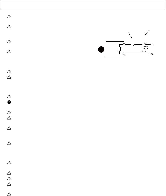
When using an inductive load such as a relay, always connect a diode as a noise measure parallel to the load.
When using a capacitance load such as a lamp, always connect a protective resistor as a noise measure serial to the load.
Do not reverse the direction of a diode which connect to a DC relay for the control output signals such as contractor and motor brake output, etc. to suppress a surge. Connecting it backwards could cause the drive unit to malfunction so that signals are not output, and
emergency stop and other safety circuits are inoperable.
Servodrive unit
|
COM |
|
|
(24VDC) |
|
RA |
Control output |
RA |
|
signal |
|
Do not connect/disconnect the cables connected between the units while the power is ON.
Securely tighten the cable connector fixing screw or fixing mechanism. An insecure fixing could cause the cable to fall off while the power is ON.
When using a shielded cable instructed in the instruction manual, always ground the cable with a cable clamp, etc.
Always separate the signals wires from the drive wire and power line.
Use wires and cables that have a wire diameter, heat resistance and flexibility that conforms to the system.
(3) Trial operation and adjustment
Check and adjust each program and parameter before starting operation. Failure to do so could lead to unforeseen operation of the machine.
Do not make remarkable adjustments and changes of parameter as the operation could become unstable.
The usable motor and unit combination is predetermined. Always check the models before starting trial operation.
The linear servomotor does not have a stopping device such as magnetic brakes. Install a stopping device on the machine side.

 CAUTION
(4) Usage methods
In abnormal state, install an external emergency stop circuit so that the operation can be stopped and power shut off immediately.
Turn the power OFF immediately if smoke, abnormal noise or odors are generated from the unit or motor.
Do not disassemble or repair this product.
Never make modifications.
When an alarm occurs, the machine will start suddenly if an alarm reset (RST) is carried out while an operation start signal (ST) is being input. Always confirm that the operation signal is OFF before carrying out an alarm reset. Failure to do so could lead to accidents or injuries.
Reduce magnetic damage by installing a noise filter. The electronic devices used near the unit could be affected by magnetic noise. Install a line noise filter, etc., if there is a risk of magnetic noise.
Use the unit, motor and regenerative resistor with the designated combination. Failure to do so could lead to fires or trouble.
The brake (magnetic brake) of the servomotor are for holding, and must not be used for normal braking.
There may be cases when holding is not possible due to the magnetic brake's life, the machine construction (when ball screw and servomotor are coupled via a timing belt, etc.) or the magnetic brake's failure. Install a stop device to ensure safety on the machine side.
After changing the programs/parameters or after maintenance and inspection, always test the operation before starting actual operation.
Do not enter the movable range of the machine during automatic operation. Never place body parts near or touch the spindle during rotation.
Follow the power supply specification conditions given in each specification for the power (input voltage, input frequency, tolerable sudden power failure time, etc.).
Set all bits to "0" if they are indicated as not used or empty in the explanation on the bits.
Do not use the dynamic brakes except during the emergency stop. Continued use of the dynamic brakes could result in brake damage.
If a circuit protector for the main circuit power supply is shared by several units, the circuit protector may not activate when a short-circuit fault occurs in a small capacity unit. This is dangerous, so never share the circuit protector.
 CAUTION
(5) Troubleshooting
If a hazardous situation is predicted during power failure or product trouble, use a servomotor with magnetic brakes or install an external brake mechanism.
Use a double circuit configuration that allows the operation circuit for the magnetic brakes to be operated even by the external emergency stop signal.
Always turn the main circuit power of the motor OFF when an alarm occurs.
If an alarm occurs, remove the cause, and secure the safety before resetting the alarm.
Shut off with the servomotor brake control output.
Servomotor
MBR
Magneticbrake
Shut off with NC brake control PLC output.
EMG
24VDC
(6) Maintenance, inspection and part replacement
Always backup the programs and parameters before starting maintenance or inspections.
The capacity of the electrolytic capacitor will drop over time due to self-discharging, etc. To prevent secondary disasters due to failures, replacing this part every five years when used under a normal environment is recommended. Contact the Service Center, Service Station, Sales Office or delayer for repairs or part replacement.
Do not perform a megger test (insulation resistance measurement) during inspections.
If the battery low warning is issued, back up the machining programs, tool data and parameters with an input/output unit, and then replace the battery.
Do not short circuit, charge, overheat, incinerate or disassemble the battery.
For after-purchase servicing of the built-in motor (including the detector), supplies of servicing parts and repairs can only be offered.
For maintenance, part replacement, and services in case of failures in the built-in motor (including the detector), take necessary actions at your end. For spindle drive unit, Mitsubishi can offer the afterpurchase servicing as with the general spindle drive unit.
When a failure has occurred in the built-in motor (including the detector), some period of time can be required to supply the servicing parts or repair. Prepare the spare parts at your end whenever possible.
(7) Disposal
Take the batteries and backlights for LCD, etc., off from the controller, drive unit and motor, and dispose of them as general industrial wastes.
Do not disassemble the unit or motor.
Dispose of the battery according to local laws.
Always return the secondary side (magnet side) of the linear servomotor to the Service Center or Service Station.
When incinerating optical communication cable, hydrogen fluoride gas or hydrogen chloride gas which is corrosive and harmful may be generated. For disposal of optical communication cable, request for specialized industrial waste disposal services that has incineration facility for disposing hydrogen fluoride gas or hydrogen chloride gas.

 CAUTION
(8) Transportation
The unit and motor are precision parts and must be handled carefully.
According to a United Nations Advisory, the battery unit and battery must be transported according to the rules set forth by the International Civil Aviation Organization (ICAO), International Air Transportation Association (IATA), International Maritime Organization (IMO), and United States Department of Transportation (DOT), etc.
(9)General precautions
The drawings given in this manual show the covers and safety partitions, etc., removed to provide a clearer explanation. Always return the covers or partitions to their respective places before starting operation, and always follow the instructions given in this manual.
Treatment of waste
The following two laws will apply when disposing of this product. Considerations must be made to each law. The following laws are in effect in Japan. Thus, when using this product overseas, the local laws will have a priority. If necessary, indicate or notify these laws to the final user of the product.
(1)Requirements for "Law for Promotion of Effective Utilization of Resources"
(a)Recycle as much of this product as possible when finished with use.
(b)When recycling, often parts are sorted into steel scraps and electric parts, etc., and sold to scrap contractors. Mitsubishi recommends sorting the product and selling the members to appropriate contractors.
(2)Requirements for "Law for Treatment of Waste and Cleaning"
(a)Mitsubishi recommends recycling and selling the product when no longer needed according to item
(1) above. The user should make an effort to reduce waste in this manner.
(b)When disposing a product that cannot be resold, it shall be treated as a waste product.
(c)The treatment of industrial waste must be commissioned to a licensed industrial waste treatment contractor, and appropriate measures, including a manifest control, must be taken.
(d)Batteries correspond to "primary batteries", and must be disposed of according to local disposal laws.

Disposal
(Note) This symbol mark is for EU countries only.
This symbol mark is according to the directive 2006/66/EC Article 20 Information for endusers and Annex II.
Your MITSUBISHI ELECTRIC product is designed and manufactured with high quality materials and components which can be recycled and/or reused.
This symbol means that batteries and accumulators, at their end-of-life, should be disposed of separately from your household waste.
If a chemical symbol is printed beneath the symbol shown above, this chemical symbol means that the battery or accumulator contains a heavy metal at a certain concentration. This will be indicated as follows:
Hg: mercury (0,0005%), Cd: cadmium (0,002%), Pb: lead (0,004%)
In the European Union there are separate collection systems for used batteries and accumulators. Please, dispose of batteries and accumulators correctly at your local community waste collection/ recycling centre.
Please, help us to conserve the environment we live in!
Contents
1 Introduction ................................................................ |
1 - 1 |
|
1-1 Servo/spindle drive system configuration ......................................................................................... |
1 - 2 |
|
1-1-1 System configuration................................................................................................................ |
1 - 2 |
|
1-2 Explanation of type ........................................................................................................................... |
1 - 3 |
|
1-2-1 Servomotor type ....................................................................................................................... |
1 - 3 |
|
1-2-2 |
Servo drive unit type................................................................................................................. |
1 - 4 |
1-2-3 |
Spindle motor type.................................................................................................................... |
1 - 5 |
1-2-4 |
Tool spindle motor type ............................................................................................................ |
1 - 6 |
1-2-5 |
Spindle drive unit type .............................................................................................................. |
1 - 7 |
2 Specifications............................................................. |
2 - 1 |
|
2-1 Servomotor ....................................................................................................................................... |
2 - 2 |
|
2-1-1 Specifications list...................................................................................................................... |
2 - 2 |
|
2-1-2 Torque characteristics .............................................................................................................. |
2 - 5 |
|
2-2 Spindle motor.................................................................................................................................... |
2 - 7 |
|
2-2-1 Specifications ........................................................................................................................... |
2 - 7 |
|
2-2-2 Output characteristics............................................................................................................. |
2 - 13 |
|
2-3 Tool spindle motor .......................................................................................................................... |
2 - 16 |
|
2-3-1 Specifications ......................................................................................................................... |
2 - 16 |
|
2-3-2 Output characteristics............................................................................................................. |
2 - 18 |
|
2-4 Drive unit......................................................................................................................................... |
2 - 20 |
|
2-4-1 Installation environment conditions ........................................................................................ |
2 - 20 |
|
2-4-2 |
Servo drive unit....................................................................................................................... |
2 - 20 |
2-4-3 |
Spindle drive unit.................................................................................................................... |
2 - 21 |
2-4-4 |
Unit outline dimension drawing............................................................................................... |
2 - 22 |
2-4-5 |
Explanation of each part......................................................................................................... |
2 - 23 |
3 Function Specifications............................................. |
3 - 1 |
Function specifications list ...................................................................................................................... |
3 - 2 |
3-1 Base functions .................................................................................................................................. |
3 - 4 |
3-1-1 Full closed loop control............................................................................................................. |
3 - 4 |
3-1-2 Position command synchronous control................................................................................... |
3 - 4 |
3-1-3 Speed command synchronous control ..................................................................................... |
3 - 5 |
3-1-4 Distance-coded reference position control ............................................................................... |
3 - 5 |
3-1-5 Spindle's continuous position loop control................................................................................ |
3 - 6 |
3-1-6 Coil changeover control............................................................................................................ |
3 - 7 |
3-1-7 Gear changeover control.......................................................................................................... |
3 - 7 |
3-1-8 Orientation control .................................................................................................................... |
3 - 7 |
3-1-9 Indexing control ........................................................................................................................ |
3 - 7 |
3-1-10 Synchronous tapping control.................................................................................................. |
3 - 7 |
3-1-11 Spindle synchronous control .................................................................................................. |
3 - 7 |
3-1-12 Spindle/C axis control............................................................................................................. |
3 - 7 |
3-1-13 Proximity switch orientation control ........................................................................................ |
3 - 7 |
3-2 Servo/Spindle control functions ........................................................................................................ |
3 - 8 |
3-2-1 Torque limit function ................................................................................................................. |
3 - 8 |
3-2-2 Variable speed loop gain control .............................................................................................. |
3 - 8 |
3-2-3 Gain changeover for synchronous tapping control................................................................... |
3 - 8 |
3-2-4 Speed loop PID changeover control......................................................................................... |
3 - 9 |
3-2-5 Disturbance torque observer .................................................................................................... |
3 - 9 |
3-2-6 Smooth High Gain control (SHG control) ................................................................................. |
3 - 9 |
3-2-7 High-speed synchronous tapping control (OMR-DD control) |
................................................... 3 - 9 |
3-2-8 Dual feedback control............................................................................................................. |
3 - 10 |
3-2-9 HAS control ............................................................................................................................ |
3 - 10 |
3-2-10 Control loop gain changeover............................................................................................... |
3 - 10 |
3-2-11 Spindle output stabilizing control .......................................................................................... |
3 - 11 |
3-2-12 High-response spindle acceleration/deceleration function ................................................... |
3 - 11 |
3-3 Compensation controls ................................................................................................................... |
3 - 12 |
3-3-1 Jitter compensation ................................................................................................................ |
3 - 12 |
3-3-2 Notch filter .............................................................................................................................. |
3 - 12 |
3-3-3 Adaptive tracking-type notch filter .......................................................................................... |
3 - 12 |
3-3-4 Overshooting compensation................................................................................................... |
3 - 13 |
3-3-5 Machine end compensation control........................................................................................ |
3 - 13 |
3-3-6 Lost motion compensation type 2........................................................................................... |
3 - 14 |
3-3-7 Lost motion compensation type 3........................................................................................... |
3 - 14 |
3-3-8 Lost motion compensation type 4........................................................................................... |
3 - 15 |
3-3-9 Spindle motor temperature compensation function ................................................................ |
3 - 15 |
3-4 Protection function .......................................................................................................................... |
3 - 16 |
3-4-1 Deceleration control at emergency stop ................................................................................. |
3 - 16 |
3-4-2 Vertical axis drop prevention/pull-up control........................................................................... |
3 - 16 |
3-4-3 Earth fault detection................................................................................................................ |
3 - 16 |
3-4-4 Collision detection function..................................................................................................... |
3 - 17 |
3-4-5 Safety observation function .................................................................................................... |
3 - 17 |
3-5 Sequence functions ........................................................................................................................ |
3 - 18 |
3-5-1 Contactor control function....................................................................................................... |
3 - 18 |
3-5-2 Motor brake control function ................................................................................................... |
3 - 18 |
3-5-3 External emergency stop function .......................................................................................... |
3 - 18 |
3-5-4 Specified speed output ........................................................................................................... |
3 - 19 |
3-5-5 Quick READY ON sequence .................................................................................................. |
3 - 19 |
3-6 Diagnosis function........................................................................................................................... |
3 - 20 |
3-6-1 Monitor output function ........................................................................................................... |
3 - 20 |
3-6-2 Machine resonance frequency display function...................................................................... |
3 - 27 |
3-6-3 Machine inertia display function ............................................................................................. |
3 - 27 |
3-6-4 Motor temperature display function ........................................................................................ |
3 - 27 |
3-6-5 Load monitor output function .................................................................................................. |
3 - 27 |
3-6-6 Open loop control function...................................................................................................... |
3 - 27 |
4 Characteristics ........................................................... |
4 - 1 |
4-1 Servomotor ....................................................................................................................................... |
4 - 2 |
4-1-1 Environmental conditions ........................................................................................................ |
4 - 2 |
4-1-2 Quakeproof level ...................................................................................................................... |
4 - 2 |
4-1-3 Shaft characteristics ................................................................................................................. |
4 - 3 |
4-1-4 Machine accuracy..................................................................................................................... |
4 - 4 |
4-1-5 Oil / water standards................................................................................................................. |
4 - 5 |
4-1-6 Flange of servo motor............................................................................................................... |
4 - 6 |
4-1-7 Overload protection characteristics .......................................................................................... |
4 - 6 |
4-1-8 Magnetic brake ....................................................................................................................... |
4 - 10 |
4-1-9 Dynamic brake characteristics ............................................................................................... |
4 - 13 |
4-2 Spindle motor.................................................................................................................................. |
4 - 15 |
4-2-1 Environmental conditions ...................................................................................................... |
4 - 15 |
4-2-2 Shaft characteristics ............................................................................................................... |
4 - 15 |
4-3 Tool spindle motor .......................................................................................................................... |
4 - 16 |
4-3-1 Environmental conditions ...................................................................................................... |
4 - 16 |
4-3-2 Shaft characteristics ............................................................................................................... |
4 - 16 |
4-3-3 Tool spindle temperature characteristics................................................................................ |
4 - 17 |
4-4 Drive unit......................................................................................................................................... |
4 - 18 |
4-4-1 Environmental conditions ...................................................................................................... |
4 - 18 |
4-4-2 Heating value.......................................................................................................................... |
4 - 18 |
5 Dedicated Options ..................................................... |
5 - 1 |
5-1 Servo options.................................................................................................................................... |
5 - 2 |
5-1-1 Battery option ........................................................................................................................... |
5 - 4 |
5-1-2 Ball screw side detector (OSA105-ET2)................................................................................... |
5 - 9 |
5-1-3 Machine side detector ............................................................................................................ |
5 - 11 |
5-2 Spindle options ............................................................................................................................... |
5 - 15 |
5-2-1 Spindle side ABZ pulse output detector (OSE-1024 Series) .................................................. |
5 - 16 |
5-2-2 Spindle side PLG serial output detector (TS5690, MU1606 Series) ...................................... |
5 - 18 |
5-2-3 Spindle side accuracy serial output detector (ERM280, MPCI Series) .................................. |
5 - 22 |
5-3 Detector interface unit..................................................................................................................... |
5 - 23 |
5-3-1 Serial output interface unit for ABZ analog detector MDS-B-HR............................................ |
5 - 23 |
5-3-2 Pulse output interface unit for ABZ analog detector IBV Series |
|
(Other manufacturer's product) .............................................................................. |
5 - 25 |
5-3-3 Serial output interface unit for ABZ analog detector EIB192M |
|
(Other manufacturer's product) .............................................................................. |
5 - 26 |
5-3-4 Serial output interface unit for ABZ analog detector EIB392M |
|
(Other manufacturer's product) .............................................................................. |
5 - 27 |
5-3-5 Serial output interface unit for ABZ analog detector ADB-20J Series |
|
(Other manufacturer's product) .............................................................................. |
5 - 28 |
5-4 Drive unit option.............................................................................................................................. |
5 - 29 |
5-4-1 Optical communication repeater unit (FCU7-EX022) ............................................................. |
5 - 29 |
5-4-2 Regenerative option ............................................................................................................... |
5 - 33 |
5-5 Cables and connectors ................................................................................................................... |
5 - 44 |
5-5-1 Cable connection diagram...................................................................................................... |
5 - 44 |
5-5-2 List of cables and connectors................................................................................................. |
5 - 45 |
5-5-3 Optical communication cable specifications ........................................................................... |
5 - 54 |
6 Specifications of Peripheral Devices ....................... |
6 - 1 |
||
6-1 Selection of wire ............................................................................................................................... |
6 - 2 |
||
6-1-1 Example of wires by unit........................................................................................................... |
6 - 2 |
||
6-2 Selection of circuit protector and contactor....................................................................................... |
6 - 4 |
||
6-2-1 |
Selection of circuit protector ..................................................................................................... |
6 - 4 |
|
6-2-2 |
Selection of contactor............................................................................................................... |
6 - 5 |
|
6-3 Selection of earth leakage breaker ................................................................................................... |
6 - 6 |
||
6-4 |
Branch-circuit protection (for control power supply) ......................................................................... |
6 - 7 |
|
6-4-1 |
Circuit protector ........................................................................................................................ |
6 - 7 |
|
6-4-2 |
Fuse protection......................................................................................................................... |
6 - 7 |
|
6-5 |
Noise filter......................................................................................................................................... |
6 - 8 |
|
6-6 |
Surge absorber ................................................................................................................................. |
6 - 9 |
|
6-7 |
Relay............................................................................................................................................... |
6 - 10 |
|
7 Selection ..................................................................... |
7 - 1 |
||
7-1 |
Selection of the servomotor .............................................................................................................. |
7 - 2 |
|
7-1-1 Outline ...................................................................................................................................... |
7 - 2 |
||
7-1-2 Selection of servomotor capacity.............................................................................................. |
7 - 3 |
||
7-1-3 Motor shaft conversion load torque ........................................................................................ |
7 - 11 |
||
7-1-4 |
Expressions for load inertia calculation .................................................................................. |
7 - 12 |
|
7-2 |
Selection of the spindle motor ........................................................................................................ |
7 - 13 |
|
7-3 |
Selection of the regenerative resistor ............................................................................................. |
7 - 14 |
|
7-3-1 |
Regeneration methods ........................................................................................................... |
7 - 14 |
|
7-3-2 |
Calculation of the regenerative energy................................................................................... |
7 - 15 |
|
7-3-3 |
Calculation of the positioning frequency................................................................................. |
7 - 17 |
|
Appendix 1 Cable and Connector Specifications
................................................... |
Appendix 1 - 1 |
Appendix 1-1 Selection of cable.............................................................................................. |
Appendix 1 - 2 |
Appendix 1-1-1 Cable wire and assembly ......................................................................... |
Appendix 1 - 2 |
Appendix 1-2 Cable connection diagram ................................................................................ |
Appendix 1 - 4 |
Appendix 1-2-1 Battery cable............................................................................................. |
Appendix 1 - 4 |
Appendix 1-2-2 Optical communication repeater unit cable .............................................. |
Appendix 1 - 5 |
Appendix 1-2-3 Servo / tool spindle detector cable ........................................................... |
Appendix 1 - 6 |
Appendix 1-2-4 Spindle detector cable ............................................................................ |
Appendix 1 - 10 |
Appendix 1-3 Connector outline dimension drawings........................................................... |
Appendix 1 - 12 |
Appendix 1-3-1 Optical communication cable.................................................................. |
Appendix 1 - 12 |
Appendix 1-3-2 DI/O or maintenance connector.............................................................. |
Appendix 1 - 14 |
Appendix 1-3-3 Servo detector connector ....................................................................... |
Appendix 1 - 15 |
Appendix 1-3-4 Brake connector ..................................................................................... |
Appendix 1 - 19 |
Appendix 1-3-5 Power connector..................................................................................... |
Appendix 1 - 21 |
Appendix 1-3-6 Drive unit side main circuit connector..................................................... |
Appendix 1 - 23 |
Appendix 1-3-7 Spindle detector connector..................................................................... |
Appendix 1 - 25 |
Appendix 2 Restrictions for Lithium Batteries |
|
................................................... |
Appendix 2 - 1 |
Appendix 2-1 Restriction for Packing ...................................................................................... |
Appendix 2 - 2 |
Appendix 2-1-1 Target Products ........................................................................................ |
Appendix 2 - 3 |
Appendix 2-1-2 Handling by User ...................................................................................... |
Appendix 2 - 4 |
Appendix 2-1-3 Reference ................................................................................................. |
Appendix 2 - 5 |
Appendix 2-2 Products information data sheet (ER battery)................................................... |
Appendix 2 - 6 |
Appendix 2-3 Issuing Domestic Law of the United States |
|
for Primary Lithium Battery Transportation....................................................... |
Appendix 2 - 8 |
Appendix 2-3-1 Outline of Regulation ................................................................................ |
Appendix 2 - 8 |
Appendix 2-3-2 Target Products ........................................................................................ |
Appendix 2 - 8 |
Appendix 2-3-3 Handling by User ...................................................................................... |
Appendix 2 - 8 |
Appendix 2-3-4 Reference ................................................................................................. |
Appendix 2 - 8 |
Appendix 2-4 Restriction related to EU Battery Directive........................................................ |
Appendix 2 - 9 |
Appendix 2-4-1 Important Notes ........................................................................................ |
Appendix 2 - 9 |
Appendix 2-4-2 Information for end-user ........................................................................... |
Appendix 2 - 9 |
Appendix 3 Compliance to EC Directives |
Appendix 3 - 1 |
................................................... |
|
Appendix 3-1 Compliance to EC Directives ............................................................................ |
Appendix 3 - 2 |
Appendix 3-1-1 European EC Directives ........................................................................... |
Appendix 3 - 2 |
Appendix 3-1-2 Cautions for EC Directive compliance ...................................................... |
Appendix 3 - 2 |
Appendix 4 EMC Installation Guidelines ... |
Appendix 4 - 1 |
Appendix 4-1 Introduction ....................................................................................................... |
Appendix 4 - 2 |
Appendix 4-2 EMC instructions............................................................................................... |
Appendix 4 - 2 |
Appendix 4-3 EMC measures ................................................................................................. |
Appendix 4 - 3 |
Appendix 4-4 Measures for panel structure ............................................................................ |
Appendix 4 - 3 |
Appendix 4-4-1 Measures for control panel unit ................................................................ |
Appendix 4 - 3 |
Appendix 4-4-2 Measures for door ................................................................................... |
Appendix 4 - 4 |
Appendix 4-4-3 Measures for operation board panel......................................................... |
Appendix 4 - 4 |
Appendix 4-4-4 Shielding of the power supply input section ............................................. |
Appendix 4 - 4 |
Appendix 4-5 Measures for various cables............................................................................. |
Appendix 4 - 5 |
|
Appendix 4-5-1 Measures for wiring in panel..................................................................... |
Appendix 4 - 5 |
|
Appendix 4-5-2 Measures for shield treatment .................................................................. |
Appendix 4 - 5 |
|
Appendix 4-5-3 Servo/spindle motor power cable ............................................................. |
Appendix 4 - 6 |
|
Appendix 4-5-4 Servo/spindle motor feedback cable ........................................................ |
Appendix 4 - 7 |
|
Appendix 4-6 EMC countermeasure parts.............................................................................. |
Appendix 4 - 8 |
|
Appendix 4-6-1 |
Shield clamp fitting ................................................................................... |
Appendix 4 - 8 |
Appendix 4-6-2 |
Ferrite core ............................................................................................... |
Appendix 4 - 9 |
Appendix 4-6-3 |
Power line filter ....................................................................................... |
Appendix 4 - 10 |
Appendix 4-6-4 |
Surge protector....................................................................................... |
Appendix 4 - 16 |
Appendix 5 EC Declaration of Conformity
................................................... |
Appendix 5 - 1 |
|
Appendix 5-1 Compliance to EC Directives ............................................................................ |
|
Appendix 5 - 2 |
Appendix 5-1-1 Low voltage equipment............................................................................. |
|
Appendix 5 - 2 |
Appendix 6 Instruction Manual for Compliance |
|
|
with UL/c-UL Standard ............ |
Appendix 6 - 1 |
|
Appendix 6-1 Operation surrounding air ambient temperature............................................... |
|
Appendix 6 - 2 |
Appendix 6-2 Notes for AC servo/spindle system................................................................... |
|
Appendix 6 - 2 |
Appendix 6-2-1 General Precaution................................................................................... |
|
Appendix 6 - 2 |
Appendix 6-2-2 Installation ................................................................................................ |
|
Appendix 6 - 2 |
Appendix 6-2-3 Short-circuit ratings (SCCR) ..................................................................... |
|
Appendix 6 - 2 |
Appendix 6-2-4 Peripheral devices .................................................................................... |
|
Appendix 6 - 3 |
Appendix 6-2-5 Field Wiring Reference Table for Input and Output (Power Wiring) ......... |
Appendix 6 - 4 |
|
Appendix 6-2-6 Motor Over Load Protection .................................................................... |
|
Appendix 6 - 7 |
Appendix 6-2-7 Flange of servo motor............................................................................... |
|
Appendix 6 - 7 |
Appendix 6-2-8 Spindle Drive/Motor Combinations ........................................................... |
|
Appendix 6 - 8 |
Appendix 6-2-9 Servo Drive/Motor Combinations.............................................................. |
|
Appendix 6 - 9 |
Appendix 6-3 AC Servo/Spindle System Connection ........................................................... |
|
Appendix 6 - 10 |
Appendix 6-3-1 MDS-D/DH/DM-Vx/SP Series................................................................. |
|
Appendix 6 - 10 |
Appendix 6-3-2 MDS-D-SVJ3/SPJ3 Series ..................................................................... |
|
Appendix 6 - 10 |
Appendix 7 Compliance with Restrictions in China |
||
................................................... |
Appendix 7 - 1 |
|
Appendix 7-1 Compliance with China CCC certification system............................................. |
|
Appendix 7 - 2 |
Appendix 7-1-1 Outline of China CCC certification system ............................................... |
|
Appendix 7 - 2 |
Appendix 7-1-2 First catalogue of products subject to compulsory product certification ... |
Appendix 7 - 3 |
|
Appendix 7-1-3 Precautions for shipping products ............................................................ |
|
Appendix 7 - 4 |
Appendix 7-1-4 Application for exemption ......................................................................... |
|
Appendix 7 - 4 |
Appendix 7-1-5 Mitsubishi NC product subject to/not subject to CCC certification............ |
Appendix 7 - 6 |
|
Appendix 7-2 Response to the China environment restrictions .............................................. |
|
Appendix 7 - 7 |
Appendix 7-2-1 Outline of the law on the pollution prevention and control |
|
|
for electronic information products ........................................................... |
|
Appendix 7 - 7 |
Appendix 7-2-2 Response to the drive product for Mitsubishi NC ..................................... |
|
Appendix 7 - 7 |
Appendix 7-2-3 Indication based on “Pollution suppression marking request |
|
|
for electronic information product”............................................................ |
|
Appendix 7 - 8 |
Outline for MDS-D-SVJ3/SPJ3 Series Instruction Manual (IB-1500193-D)
1 Installation
1-1 Installation of servomotor
1-1-1 Environmental conditions
1-1-2 Quakeproof level
1-1-3 Cautions for mounting load (prevention of impact on shaft)
1-1-4 Installation direction
1-1-5 Shaft characteristics
1-1-6 Machine accuracy
1-1-7 Coupling with the load
1-1-8 Oil/water standards
1-1-9 Installation of servomotor
1-1-10 Cable stress
1-2 Installation of spindle motor
1-2-1 Environmental conditions
1-2-2 Shaft characteristics
1-3 Installation of tool spindle motor
1-3-1 Environmental conditions
1-3-2 Shaft characteristics
1-4 Installation of the drive unit
1-4-1 Environmental conditions
1-4-2 Installation direction and clearance 1-4-3 Prevention of entering of foreign matter 1-4-4 Heating value
1-4-5 Heat radiation countermeasures
1-5 Installation of the spindle detector
1-5-1 Spindle side ABZ pulse output detector (OSE-1024 Series)
1-5-2 Spindle side PLG serial output detector (TS5690, MU1606 Series)
1-5-3 Installation accuracy diagnosis for PLG detector
1-6 Noise measures
2 Wiring and Connection
2-1 Part system connection diagram
2-2 Main circuit terminal block/control circuit connector
2-2-1 Names and applications of main circuit terminal block signals and control circuit connectors
2-2-2 Connector pin assignment
2-2-3 Main circuit connector (CNP1,CNP2,CNP3) wiring method
2-3 NC and drive unit connection
2-4 Connecting with optical communication repeater unit
2-5 Motor and detector connection
2-5-1 Connection of the servomotor
2-5-2 Connection of the full-closed loop system 2-5-3 Connection of the spindle motor
2-5-4 Connection of the tool spindle motor 2-6 Connection of power supply
2-6-1 Power supply input connection
2-6-2 Connection of the grounding cable 2-7 Connection of regenerative resistor
2-7-1 Standard built-in regenerative resistor (Only for MDS-D-SVJ3)
2-7-2 External option regenerative resistor
2-8 Wiring of the peripheral control 2-8-1 Wiring of the Input/output circuit 2-8-2 Wiring of the contactor control
2-8-3 Wiring of the motor magnetic brake (MDS- D-SVJ3)
2-8-4 Wiring of an external emergency stop 2-8-5 Safety observation function
2-8-6 Specifications of proximity switch
3 Setup
3-1 Initial setup
3-1-1 Setting the rotary switch
3-1-2 Setting DIP switch
3-1-3 Transition of LED display after power is turned ON
3-2 Setting the initial parameters for the servo drive unit
3-2-1 Setting of servo specification parameters 3-2-2 Setting of machine side detector
3-2-3 List of standard parameters for each servomotor
3-2-4 Servo parameters
3-3 Setting the initial parameters for the spindle drive unit
3-3-1 Setting of parameters related to the spindle 3-3-2 List of standard parameters for each spindle
motor
3-3-3 Spindle specification parameters
3-3-4 Spindle parameters
4 Servo Adjustment
4-1 D/A output specifications for servo drive unit 4-1-1 D/A output specifications
4-1-2 Output data settings
4-1-3 Setting the output magnification
4-2 Servo adjustment procedure
4-3 Gain adjustment
4-3-1 Current loop gain
4-3-2 Speed loop gain
4-3-3 Position loop gain
4-4 Characteristics improvement
4-4-1 Optimal adjustment of cycle time 4-4-2 Vibration suppression measures 4-4-3 Improving the cutting surface precision 4-4-4 Improvement of characteristics during
acceleration/deceleration 4-4-5 Improvement of protrusion at quadrant
changeover
4-4-6 Improvement of overshooting
4-4-7 Improvement of the interpolation control path
4-5 Adjustment during full closed loop control
4-5-1 Outline
4-5-2 Speed loop delay compensation
4-5-3 Dual feedback control
4-6 Settings for emergency stop
4-6-1 Deceleration control
4-6-2 Vertical axis drop prevention control 4-6-3 Vertical axis pull-up control
4-7 Protective functions
4-7-1 Overload detection
4-7-2 Excessive error detection
4-7-3 Collision detection function
4-8 Servo control signal
4-8-1 Servo control input (NC to Servo) 4-8-2 Servo control output (Servo to NC)
7 Maintenance
7-1 Periodic inspections
7-1-1 Inspections
7-1-2 Cleaning of spindle motor
7-2 Service parts
7-3 Adding and replacing units and parts
7-3-1 Replacing the drive unit
7-3-2 Replacing the unit fan
7-3-3 Replacing the battery
Appendix 1 Cable and Connector
Specifications
5 Spindle Adjustment
5-1 D/A output specifications for spindle drive unit 5-1-1 D/A output specifications
5-1-2 Setting the output data
5-1-3 Setting the output magnification
5-2 Adjustment procedures for each control
5-2-1 Basic adjustments
5-2-2 Gain adjustment
5-2-3 Adjusting the acceleration/deceleration operation
5-2-4 Orientation adjustment
5-2-5 Synchronous tapping adjustment 5-2-6 Spindle C axis adjustment (For lathe
system)
5-2-7 Spindle synchronization adjustment (For lathe system)
5-2-8 Deceleration coil changeover valid function by emergency stop
5-2-9 High-response acceleration/deceleration function
5-2-10 Spindle cutting withstand level improvement
5-3 Settings for emergency stop
5-3-1 Deceleration control
5-4 Spindle control signal
5-4-1 Spindle control input (NC to Spindle) 5-4-2 Spindle control output (Spindle to NC)
6 Troubleshooting
6-1 Points of caution and confirmation
6-1-1 LED display when alarm or warning occurs 6-2 Protective functions list of units
6-2-1 List of alarms
6-2-2 List of warnings
6-3 Troubleshooting
6-3-1 Troubleshooting at power ON 6-3-2 Troubleshooting for each alarm No.
6-3-3 Troubleshooting for each warning No. 6-3-4 Parameter numbers during initial parameter
error
6-3-5 Troubleshooting the spindle system when there is no alarm or warning
Appendix 1-1 Selection of cable
Appendix 1-1-1 Cable wire and assembly Appendix 1-2 Cable connection diagram
Appendix 1-2-1 Battery cable
Appendix 1-2-2 Optical communication repeater unit cable
Appendix 1-2-3 Servo / tool spindle detector cable Appendix 1-2-4 Spindle detector cable
Appendix 1-3 Connector outline dimension drawings Appendix 1-3-1 Optical communication cable Appendix 1-3-2 DI/O or maintenance connector Appendix 1-3-3 Servo detector connector Appendix 1-3-4 Brake connector
Appendix 1-3-5 Power connector Appendix 1-3-6 Drive unit side main circuit
connector
Appendix 1-3-7 Spindle detector connector
Appendix 2 Cable and Connector Assembly
Appendix 2-1 CM10-SPxxS-x(D6) plug connector Appendix 2-2 CM10-APxxS-x(D6) angle plug
connector
Appendix 2-3 CM10-SP-CV reinforcing cover for straight plug
Appendix 2-4 CM10-AP-D-CV reinforcing cover for angle plug
Appendix 2-5 1747464-1 plug connector Appendix 2-5-1 Applicable products Appendix 2-5-2 Applicable cable Appendix 2-5-3 Related documents Appendix 2-5-4 Assembly procedure
Appendix 3 Precautions in Installing Spindle Motor
Appendix 3-1 Precautions in transporting motor Appendix 3-2 Precautions in selecting motor fittings Appendix 3-3 Precautions in mounting fittings Appendix 3-4 Precautions in coupling shafts Appendix 3-5 Precautions in installing motor in
machine Appendix 3-6 Other Precautions
Appendix 3-7 Example of unbalance correction
Appendix 3-8 Precautions in balancing of motor with key
Appendix 4 Compliance to EC Directives
Appendix 4-1 Compliance to EC Directives Appendix 4-1-1 European EC Directives Appendix 4-1-2 Cautions for EC Directive
compliance
Appendix 5 EMC Installation Guidelines
Appendix 5-1 Introduction Appendix 5-2 EMC instructions Appendix 5-3 EMC measures
Appendix 5-4 Measures for panel structure Appendix 5-4-1 Measures for control panel unit Appendix 5-4-2 Measures for door
Appendix 5-4-3 Measures for operation board panel
Appendix 5-4-4 Shielding of the power supply input section
Appendix 5-5 Measures for various cables Appendix 5-5-1 Measures for wiring in panel Appendix 5-5-2 Measures for shield treatment Appendix 5-5-3 Servo/spindle motor power cable Appendix 5-5-4 Servo/spindle motor feedback
cable
Appendix 5-6 EMC countermeasure parts Appendix 5-6-1 Shield clamp fitting Appendix 5-6-2 Ferrite core
Appendix 5-6-3 Power line filter Appendix 5-6-4 Surge protector
Appendix 6 EC Declaration of Conformity
Appendix 6-1 Compliance to EC Directives Appendix 6-1-1 Low voltage equipment
Appendix 7 Higher Harmonic Suppression Measure Guidelines
Appendix 7-1 Higher harmonic suppression measure guidelines
Appendix 7-1-1 Calculating the equivalent capacity of the higher harmonic generator
Loading...