


 Loading...
Mitsubishi MR-J4W3-222B, MR-J4W3-444B, MR-J4W2-44B, MR-J4W2-1010B, MR-J4W2-22B User Manual
...General-Purpose AC Servo
SSCNET  /H Interface Multi-axis AC Servo
MODEL
MR-J4W2-_B
MR-J4W3-_B
SERVO AMPLIFIER INSTRUCTION MANUAL

 6DIHW\ ,QVWUXFWLRQV
3OHDVH UHDG WKH LQVWUXFWLRQV FDUHIXOO\ EHIRUH XVLQJ WKH HTXLSPHQW
7R XVH WKH HTXLSPHQW FRUUHFWO\ GR QRW DWWHPSW WR LQVWDOO RSHUDWH PDLQWDLQ RU LQVSHFW WKH HTXLSPHQW XQWLO
\RX KDYH UHDG WKURXJK WKLV ,QVWUXFWLRQ 0DQXDO ,QVWDOODWLRQ JXLGH DQG DSSHQGHG GRFXPHQWV FDUHIXOO\ 'R QRW
XVH WKH HTXLSPHQW XQWLO \RX KDYH D IXOO NQRZOHGJH RI WKH HTXLSPHQW VDIHW\ LQIRUPDWLRQ DQG LQVWUXFWLRQV ,Q WKLV ,QVWUXFWLRQ 0DQXDO WKH VDIHW\ LQVWUXFWLRQ OHYHOV DUH FODVVLILHG LQWR :$51,1* DQG &$87,21
|
|
|
|
|
|
|
:$51,1* |
|
UHVXOWLQJ LQ GHDWK RU VHYHUH LQMXU\,QGLFDWHV WKDW LQFRUUHFW KDQGOLQJ PD\ FDXVH KD]DUGRXV FRQGLWLRQV |
|
|
|
|
|
|
|
&$87,21 |
|
UHVXOWLQJ LQ PHGLXP RU VOLJKW LQMXU\ WR SHUVRQQHO RU PD\ FDXVH SK\VLFDO,QGLFDWHV WKDW LQFRUUHFW KDQGOLQJ PD\ FDXVH KD]DUGRXV FRQGLWLRQV |
|
|
|
GDPDJH |
|
|
|
|
|
|
1RWH WKDW WKH &$87,21 OHYHO PD\ OHDG WR D VHULRXV FRQVHTXHQFH DFFRUGLQJ WR FRQGLWLRQV 3OHDVH IROORZ WKH LQVWUXFWLRQV RI ERWK OHYHOV EHFDXVH WKH\ DUH LPSRUWDQW WR SHUVRQQHO VDIHW\ :KDW PXVW QRW EH GRQH DQG ZKDW PXVW EH GRQH DUH LQGLFDWHG E\ WKH IROORZLQJ GLDJUDPPDWLF V\PEROV
 ,QGLFDWHV ZKDW PXVW QRW EH GRQH )RU H[DPSOH 1R )LUH LV LQGLFDWHG E\
 ,QGLFDWHV ZKDW PXVW EH GRQH )RU H[DPSOH JURXQGLQJ LV LQGLFDWHG E\
,Q WKLV ,QVWUXFWLRQ 0DQXDO LQVWUXFWLRQV DW D ORZHU OHYHO WKDQ WKH DERYH LQVWUXFWLRQV IRU RWKHU IXQFWLRQV DQG VR
RQ DUH FODVVLILHG LQWR 32,17 $IWHU UHDGLQJ WKLV ,QVWUXFWLRQ 0DQXDO NHHS LW DFFHVVLEOH WR WKH RSHUDWRU
$

7R SUHYHQW HOHFWULF VKRFN QRWH WKH IROORZLQJ
 :$51,1*
 %HIRUH ZLULQJ DQG LQVSHFWLRQV WXUQ RII WKH SRZHU DQG ZDLW IRU PLQXWHV RU PRUH XQWLO WKH FKDUJH ODPS WXUQV RII 7KHQ FRQILUP WKDW WKH YROWDJH EHWZHHQ 3 DQG 1 LV VDIH ZLWK D YROWDJH WHVWHU DQG RWKHUV 2WKHUZLVH DQ HOHFWULF VKRFN PD\ RFFXU ,Q DGGLWLRQ ZKHQ FRQILUPLQJ ZKHWKHU WKH FKDUJH ODPS LV RII RU QRW DOZD\V FRQILUP LW IURP WKH IURQW RI WKH VHUYR DPSOLILHU
  *URXQG WKH VHUYR DPSOLILHU DQG VHUYR PRWRU VHFXUHO\
  $Q\ SHUVRQ ZKR LV LQYROYHG LQ ZLULQJ DQG LQVSHFWLRQ VKRXOG EH IXOO\ FRPSHWHQW WR GR WKH ZRUN
  'R QRW DWWHPSW WR ZLUH WKH VHUYR DPSOLILHU DQG VHUYR PRWRU XQWLO WKH\ KDYH EHHQ LQVWDOOHG 2WKHUZLVH LW PD\ FDXVH DQ HOHFWULF VKRFN
  'R QRW RSHUDWH VZLWFKHV ZLWK ZHW KDQGV 2WKHUZLVH LW PD\ FDXVH DQ HOHFWULF VKRFN
  7KH FDEOHV VKRXOG QRW EH GDPDJHG VWUHVVHG ORDGHG RU SLQFKHG 2WKHUZLVH LW PD\ FDXVH DQ HOHFWULF VKRFN
 7R SUHYHQW DQ HOHFWULF VKRFN DOZD\V FRQQHFW WKH SURWHFWLYH HDUWK 3( WHUPLQDO PDUNHG
 RI WKH VHUYR DPSOLILHU WR WKH SURWHFWLYH HDUWK 3( RI WKH FDELQHW
 :KHQ XVLQJ D UHVLGXDO FXUUHQW GHYLFH 5&' VHOHFW WKH W\SH %
 7R DYRLG DQ HOHFWULF VKRFN LQVXODWH WKH FRQQHFWLRQV RI WKH SRZHU VXSSO\ WHUPLQDOV
7R SUHYHQW ILUH QRWH WKH IROORZLQJ
 &$87,21
,QVWDOO WKH VHUYR DPSOLILHU VHUYR PRWRU DQG UHJHQHUDWLYH UHVLVWRU RQ LQFRPEXVWLEOH PDWHULDO ,QVWDOOLQJ LW
GLUHFWO\ RU FORVH WR FRPEXVWLEOHV ZLOO OHDG WR D ILUH
 $OZD\V FRQQHFW D PDJQHWLF FRQWDFWRU EHWZHHQ WKH SRZHU VXSSO\ DQG WKH PDLQ FLUFXLW SRZHU VXSSO\ / / DQG / RI WKH VHUYR DPSOLILHU LQ RUGHU WR FRQILJXUH D FLUFXLW WKDW VKXWV GRZQ WKH SRZHU VXSSO\ RQ WKH VLGH RI WKH VHUYR DPSOLILHU¶V SRZHU VXSSO\ ,I D PDJQHWLF FRQWDFWRU LV QRW FRQQHFWHG FRQWLQXRXV IORZ RI D ODUJH FXUUHQW PD\ FDXVH D ILUH ZKHQ WKH VHUYR DPSOLILHU PDOIXQFWLRQV
 :KHQ XVLQJ WKH UHJHQHUDWLYH UHVLVWRU VZLWFK SRZHU RII ZLWK WKH DODUP VLJQDO 1RW GRLQJ VR PD\ FDXVH D ILUH ZKHQ D UHJHQHUDWLYH WUDQVLVWRU PDOIXQFWLRQV RU WKH OLNH PD\ RYHUKHDW WKH UHJHQHUDWLYH UHVLVWRU
 3URYLGH DGHTXDWH SURWHFWLRQ WR SUHYHQW VFUHZV DQG RWKHU FRQGXFWLYH PDWWHU RLO DQG RWKHU FRPEXVWLEOH PDWWHU IURP HQWHULQJ WKH VHUYR DPSOLILHU DQG VHUYR PRWRU
 $OZD\V FRQQHFW D PROGHG FDVH FLUFXLW EUHDNHU WR WKH SRZHU VXSSO\ RI WKH VHUYR DPSOLILHU
 &RQQHFWLQJ DQ HQFRGHU IRU GLIIHUHQW D[LV WR WKH &1$&1 % RU &1 & FRQQHFWRU PD\ FDXVH D ILUH
7R SUHYHQW LQMXU\ QRWH WKH IROORZLQJ
 &$87,21
 2QO\ WKH YROWDJH VSHFLILHG LQ WKH ,QVWUXFWLRQ 0DQXDO VKRXOG EH DSSOLHG WR HDFK WHUPLQDO 2WKHUZLVH D EXUVW GDPDJH HWF PD\ RFFXU
 &RQQHFW FDEOHV WR WKH FRUUHFW WHUPLQDOV 2WKHUZLVH D EXUVW GDPDJH HWF PD\ RFFXU
 (QVXUH WKDW SRODULW\ LV FRUUHFW 2WKHUZLVH D EXUVW GDPDJH HWF PD\ RFFXU
 7KH VHUYR DPSOLILHU KHDW VLQN UHJHQHUDWLYH UHVLVWRU VHUYR PRWRU HWF PD\ EH KRW ZKLOH SRZHU LV RQ RU IRU VRPH WLPH DIWHU SRZHU RII 7DNH VDIHW\ PHDVXUHV H J SURYLGH FRYHUV WR SUHYHQW DFFLGHQWDO FRQWDFW RI
KDQGV DQG SDUWV FDEOHV HWF ZLWK WKHP
$

$GGLWLRQDO LQVWUXFWLRQV
7KH IROORZLQJ LQVWUXFWLRQV VKRXOG DOVR EH IXOO\ QRWHG ,QFRUUHFW KDQGOLQJ PD\ FDXVH D PDOIXQFWLRQ LQMXU\
HOHFWULF VKRFN HWF
7UDQVSRUWDWLRQ DQG LQVWDOODWLRQ
 &$87,21
|
7UDQVSRUW WKH SURGXFWV FRUUHFWO\ DFFRUGLQJ WR WKHLU PDVV |
|||
|
6WDFNLQJ LQ H[FHVV RI WKH VSHFLILHG QXPEHU RI SURGXFW SDFNDJHV LV QRW DOORZHG |
|||
|
,QVWDOO WKH VHUYR DPSOLILHU DQG WKH VHUYR PRWRU LQ D ORDG EHDULQJ SODFH LQ DFFRUGDQFH ZLWK WKH ,QVWUXFWLRQ |
|||
|
0DQXDO |
|
|
|
|
'R QRW JHW RQ RU SXW KHDY\ ORDG RQ WKH HTXLSPHQW |
|||
|
7KH HTXLSPHQW PXVW EH LQVWDOOHG LQ WKH VSHFLILHG GLUHFWLRQ |
|||
|
/HDYH VSHFLILHG FOHDUDQFHV EHWZHHQ WKH VHUYR DPSOLILHU DQG WKH FDELQHW ZDOOV RU RWKHU HTXLSPHQW |
|||
|
'R QRW LQVWDOO RU RSHUDWH WKH VHUYR DPSOLILHU DQG VHUYR PRWRU ZKLFK KDYH EHHQ GDPDJHG RU KDYH DQ\ |
|||
|
SDUWV PLVVLQJ |
|
|
|
|
:KHQ \RX NHHS RU XVH WKH HTXLSPHQW SOHDVH IXOILOO WKH IROORZLQJ HQYLURQPHQW |
|||
|
,WHP |
(QYLURQPHQW |
|
|
|
$PELHQW |
2SHUDWLRQ |
& WR & QRQ IUHH]LQJ |
|
|
WHPSHUDWXUH |
6WRUDJH |
& WR & QRQ IUHH]LQJ |
|
|
$PELHQW |
2SHUDWLRQ |
5+ RU OHVV QRQ FRQGHQVLQJ |
|
|
KXPLGLW\ |
6WRUDJH |
|
|
|
|
|||
|
$PELHQFH |
,QGRRUV QR GLUHFW VXQOLJKW IUHH IURP FRUURVLYH JDV IODPPDEOH JDV RLO PLVW GXVW DQG GLUW |
|
|
|
$OWLWXGH |
0D[ P DERYH VHD OHYHO |
|
|
|
9LEUDWLRQ |
P V RU OHVV DW +] WR +] GLUHFWLRQV RI ; < DQG = D[HV |
|
|
 'R QRW EORFN WKH LQWDNH DQG H[KDXVW DUHDV RI WKH VHUYR DPSOLILHU 2WKHUZLVH LW PD\ FDXVH D PDOIXQFWLRQ
 'R QRW GURS RU VWULNH WKH VHUYR DPSOLILHU DQG VHUYR PRWRU ,VRODWH WKHP IURP DOO LPSDFW ORDGV
 :KHQ WKH HTXLSPHQW KDV EHHQ VWRUHG IRU DQ H[WHQGHG SHULRG RI WLPH FRQWDFW \RXU ORFDO VDOHV RIILFH
 :KHQ KDQGOLQJ WKH VHUYR DPSOLILHU EH FDUHIXO DERXW WKH HGJHG SDUWV VXFK DV FRUQHUV RI WKH VHUYR DPSOLILHU
 7KH VHUYR DPSOLILHU PXVW EH LQVWDOOHG LQ WKH PHWDO FDELQHW
:LULQJ
 &$87,21
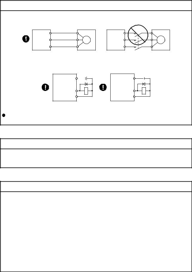
 :LUH WKH HTXLSPHQW FRUUHFWO\ DQG VHFXUHO\ 2WKHUZLVH WKH VHUYR PRWRU PD\ RSHUDWH XQH[SHFWHGO\
 'R QRW LQVWDOO D SRZHU FDSDFLWRU VXUJH NLOOHU RU UDGLR QRLVH ILOWHU )5 %,) RSWLRQ RQ WKH VHUYR DPSOLILHU RXWSXW VLGH 7R DYRLG D PDOIXQFWLRQ FRQQHFW WKH ZLUHV WR WKH FRUUHFW SKDVH WHUPLQDOV 8 9 DQG : RI WKH VHUYR
DPSOLILHU DQG VHUYR PRWRU
$
 &$87,21
 &RQQHFW WKH VHUYR DPSOLILHU SRZHU RXWSXW 8 9 DQG : WR WKH VHUYR PRWRU SRZHU LQSXW 8 9 DQG : GLUHFWO\ 'R QRW OHW D PDJQHWLF FRQWDFWRU HWF LQWHUYHQH 2WKHUZLVH LW PD\ FDXVH D PDOIXQFWLRQ
6HUYR DPSOLILHU |
8 |
6HUYR PRWRU |
6HUYR DPSOLILHU |
8 |
6HUYR PRWRU |
|
8 |
|
|
8 |
|
|
|
9 |
9 |
0 |
9 |
9 |
0 |
|
|
|
|
||||
: |
: |
|
: |
: |
|
|
|
|
|
|
|
 7KH VXUJH DEVRUELQJ GLRGH LQVWDOOHG WR WKH '& UHOD\ IRU FRQWURO RXWSXW VKRXOG EH ILWWHG LQ WKH VSHFLILHG GLUHFWLRQ 2WKHUZLVH WKH HPHUJHQF\ VWRS DQG RWKHU SURWHFWLYH FLUFXLWV PD\ QRW RSHUDWH
6HUYR DPSOLILHU |
9 '& |
|
'2&20 |
||
|
||
&RQWURO RXWSXW |
5$ |
|
VLJQDO |
||
|
||
',&20 |
|
|
)RU VLQN RXWSXW LQWHUIDFH |
||
|
6HUYR DPSOLILHU |
9 '& |
|
|
'2&20 |
|
|
|
|
|
|
|
&RQWURO RXWSXW |
5$ |
|
|
VLJQDO |
|
|
|
|
|
|
|
',&20 |
|
|
|
)RU VRXUFH RXWSXW LQWHUIDFH |
|
|
:KHQ WKH FDEOH LV QRW WLJKWHQHG HQRXJK WR WKH WHUPLQDO EORFN WKH FDEOH RU WHUPLQDO EORFN PD\ JHQHUDWH
KHDW EHFDXVH RI WKH SRRU FRQWDFW %H VXUH WR WLJKWHQ WKH FDEOH ZLWK VSHFLILHG WRUTXH
7HVW UXQ DQG DGMXVWPHQW
 &$87,21
 %HIRUH RSHUDWLRQ FKHFN WKH SDUDPHWHU VHWWLQJV ,PSURSHU VHWWLQJV PD\ FDXVH VRPH PDFKLQHV WR SHUIRUP XQH[SHFWHG RSHUDWLRQ
 1HYHU DGMXVW RU FKDQJH WKH SDUDPHWHU YDOXHV H[WUHPHO\ DV LW ZLOO PDNH RSHUDWLRQ XQVWDEOH
8VDJH
 &$87,21
 3URYLGH DQ H[WHUQDO HPHUJHQF\ VWRS FLUFXLW WR HQVXUH WKDW RSHUDWLRQ FDQ EH VWRSSHG DQG SRZHU VZLWFKHG RII LPPHGLDWHO\
 'R QRW GLVDVVHPEOH UHSDLU RU PRGLI\ WKH HTXLSPHQW
 %HIRUH UHVHWWLQJ DQ DODUP PDNH VXUH WKDW WKH UXQ VLJQDO RI WKH VHUYR DPSOLILHU LV RII LQ RUGHU WR SUHYHQW D VXGGHQ UHVWDUW 2WKHUZLVH LW PD\ FDXVH DQ DFFLGHQW
 8VH D QRLVH ILOWHU HWF WR PLQLPL]H WKH LQIOXHQFH RI HOHFWURPDJQHWLF LQWHUIHUHQFH (OHFWURPDJQHWLF LQWHUIHUHQFH PD\ EH JLYHQ WR WKH HOHFWURQLF HTXLSPHQW XVHG QHDU WKH VHUYR DPSOLILHU
 %XUQLQJ RU EUHDNLQJ D VHUYR DPSOLILHU PD\ FDXVH D WR[LF JDV 'R QRW EXUQ RU EUHDN LW
 8VH WKH VHUYR DPSOLILHU ZLWK WKH VSHFLILHG VHUYR PRWRU
 7KH HOHFWURPDJQHWLF EUDNH RQ WKH VHUYR PRWRU LV GHVLJQHG WR KROG WKH PRWRU VKDIW DQG VKRXOG QRW EH XVHG IRU RUGLQDU\ EUDNLQJ
 )RU VXFK UHDVRQV DV VHUYLFH OLIH DQG PHFKDQLFDO VWUXFWXUH H J ZKHUH D EDOO VFUHZ DQG WKH VHUYR PRWRU DUH FRXSOHG YLD D WLPLQJ EHOW WKH HOHFWURPDJQHWLF EUDNH PD\ QRW KROG WKH PRWRU VKDIW 7R HQVXUH VDIHW\
LQVWDOO D VWRSSHU RQ WKH PDFKLQH VLGH
$
&RUUHFWLYH DFWLRQV
 &$87,21
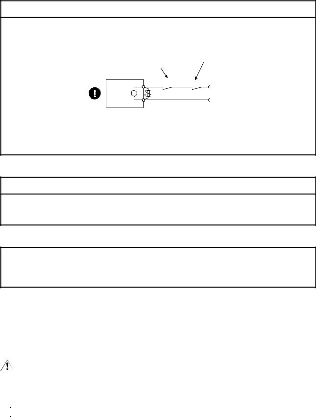
 :KHQ LW LV DVVXPHG WKDW D KD]DUGRXV FRQGLWLRQ PD\ RFFXU GXH WR D SRZHU IDLOXUH RU SURGXFW PDOIXQFWLRQ XVH D VHUYR PRWRU ZLWK DQ HOHFWURPDJQHWLF EUDNH RU H[WHUQDO EUDNH WR SUHYHQW WKH FRQGLWLRQ
  &RQILJXUH DQ HOHFWURPDJQHWLF EUDNH FLUFXLW VR WKDW LW LV DFWLYDWHG DOVR E\ DQ H[WHUQDO (0* VWRS VZLWFK
Contacts must be opened when CALM(And
&RQWDFWV PXVW EH RSHQHG ZKHQ$/0 &RQWDFWV PXVW EH RSHQHG malfunction)0DOIXQFWLRQor MBR(ElectromagneticU 0%5 B (OHFWURPDJQHWLFbrake ZLWK WKH (0* VWRS VZLWFK interlock)EUDNH LQWHUORFNB WXUQV RIIturns off.
6HUYR PRWRU |
|
5$ |
|
% |
9 '& |
(OHFWURPDJQHWLF EUDNH |
|
 :KHQ DQ\ DODUP KDV RFFXUUHG HOLPLQDWH LWV FDXVH HQVXUH VDIHW\ DQG GHDFWLYDWH WKH DODUP EHIRUH UHVWDUWLQJ RSHUDWLRQ
 3URYLGH DQ DGHTXDWH SURWHFWLRQ WR SUHYHQW XQH[SHFWHG UHVWDUW DIWHU DQ LQVWDQWDQHRXV SRZHU IDLOXUH
0DLQWHQDQFH LQVSHFWLRQ DQG SDUWV UHSODFHPHQW
 &$87,21
 :LWK DJH WKH HOHFWURO\WLF FDSDFLWRU RI WKH VHUYR DPSOLILHU ZLOO GHWHULRUDWH 7R SUHYHQW D VHFRQGDU\ DFFLGHQW GXH WR D PDOIXQFWLRQ LW LV UHFRPPHQG WKDW WKH HOHFWURO\WLF FDSDFLWRU EH UHSODFHG HYHU\ \HDUV
ZKHQ LW LV XVHG LQ JHQHUDO HQYLURQPHQW 3OHDVH FRQWDFW \RXU ORFDO VDOHV RIILFH
*HQHUDO LQVWUXFWLRQ
 7R LOOXVWUDWH GHWDLOV WKH HTXLSPHQW LQ WKH GLDJUDPV RI WKLV ,QVWUXFWLRQ 0DQXDO PD\ KDYH EHHQ GUDZQ ZLWKRXW FRYHUV DQG VDIHW\ JXDUGV :KHQ WKH HTXLSPHQW LV RSHUDWHG WKH FRYHUV DQG VDIHW\ JXDUGV PXVW EH LQVWDOOHG DV VSHFLILHG 2SHUDWLRQ PXVW EH SHUIRUPHG LQ DFFRUGDQFH ZLWK WKLV 6SHFLILFDWLRQV DQG
,QVWUXFWLRQ 0DQXDO
 ',6326$/ 2) :$67(
3OHDVH GLVSRVH D VHUYR DPSOLILHU EDWWHU\ SULPDU\ EDWWHU\ DQG RWKHU RSWLRQV DFFRUGLQJ WR \RXU ORFDO ODZV DQG
UHJXODWLRQV
((3 520 OLIH
7KH QXPEHU RI ZULWH WLPHV WR WKH ((3 520 ZKLFK VWRUHV SDUDPHWHU VHWWLQJV HWF LV OLPLWHG WR ,I
WKH WRWDO QXPEHU RI WKH IROORZLQJ RSHUDWLRQV H[FHHGV WKH VHUYR DPSOLILHU PD\ PDOIXQFWLRQ ZKHQ WKH
((3 520 UHDFKHV WKH HQG RI LWV XVHIXO OLIH
:ULWH WR WKH ((3 520 GXH WR SDUDPHWHU VHWWLQJ FKDQJHV
:ULWH WR WKH ((3 520 GXH WR GHYLFH FKDQJHV
$

672 IXQFWLRQ RI WKH VHUYR DPSOLILHU
:KHQ XVLQJ WKH 672 IXQFWLRQ RI WKH VHUYR DPSOLILHU UHIHU WR FKDSWHU )RU WKH 05-' VDIHW\ ORJLF XQLW UHIHU WR DSSHQGL[
&203/,$1&( :,7+ &( 0$5.,1*
5HIHU WR$SSHQGL[ IRU WKH FRPSOLDQFH ZLWK &( PDUNLQJ
&203/,$1&( :,7+ 8/ &6$67$1'$5'
5HIHU WR$SSHQGL[ IRU WKH FRPSOLDQFH ZLWK 8/ &6$VWDQGDUG
$ERXW WKH PDQXDOV!!
<RX PXVW KDYH WKLV ,QVWUXFWLRQ 0DQXDO DQG WKH IROORZLQJ PDQXDOV WR XVH WKLV VHUYR (QVXUH WR SUHSDUH
WKHP WR XVH WKH VHUYR VDIHO\
5HOHYDQW PDQXDOV
|
|
|
0DQXDO QDPH |
0DQXDO 1R |
|
|
0(/6(592-6HULHV ,QVWUXFWLRQV DQG &DXWLRQV IRU 6DIH 8VH RI$& 6HUYRV |
,% 1$ 5 |
|
|
|
3DFNHG ZLWK WKH VHUYR DPSOLILHU |
|
|
|
|
0(/6(592-6(592$03/,),(5 ,16758&7,21 0$18$/ 7528%/(6+227,1* |
6+ 1$ |
|
|
|
0(/6(592 6HUYR 0RWRU ,QVWUXFWLRQ 0DQXDO 9RO 1RWH |
6+ 1$ |
|
|
|
0(/6(592 /LQHDU 6HUYR 0RWRU ,QVWUXFWLRQ 0DQXDO 1RWH |
6+ 1$ |
|
|
|
0(/6(592 'LUHFW 'ULYH 0RWRU ,QVWUXFWLRQ 0DQXDO 1RWH |
6+ 1$ |
|
|
|
0(/6(592 /LQHDU (QFRGHU ,QVWUXFWLRQ 0DQXDO 1RWH |
6+ 1$ |
|
|
|
(0& ,QVWDOODWLRQ *XLGHOLQHV |
,% 1$ |
|
1RWH |
,W LV QHFHVVDU\ IRU XVLQJ D URWDU\ VHUYR PRWRU |
|
||
|
|
|||
|
|
,W LV QHFHVVDU\ IRU XVLQJ D OLQHDU VHUYR PRWRU |
|
|
|
|
,W LV QHFHVVDU\ IRU XVLQJ D GLUHFW GULYH PRWRU |
|
|
|
|
,W LV QHFHVVDU\ IRU XVLQJ D IXOO\ FORVHG ORRS V\VWHP |
|
|
|
|
|
|
|
:LULQJ!! |
|
|
|
|
:LUHV PHQWLRQHG LQ WKLV ,QVWUXFWLRQ 0DQXDO DUH VHOHFWHG EDVHG RQ WKH DPELHQW WHPSHUDWXUH RI &
)
8 6 FXVWRPDU\ XQLWV!!
8 6 FXVWRPDU\ XQLWV DUH QRW VKRZQ LQ WKLV PDQXDO &RQYHUW WKH YDOXHV LI QHFHVVDU\ DFFRUGLQJ WR WKH
IROORZLQJ WDEOH
4XDQWLW\ |
6, PHWULF XQLW |
8 6 FXVWRPDU\ XQLW |
0DVV |
>NJ@ |
>OE@ |
/HQJWK |
>PP@ |
>LQ@ |
7RUTXH |
>1 P@ |
>R] LQ@ |
0RPHQW RI LQHUWLD |
> NJ P @ |
>R] LQ @ |
/RDG WKUXVW ORDG D[LDO ORDG |
>1@ |
>OEI@ |
7HPSHUDWXUH |
1 > &@ |
1 > )@ |
$
|
|
|
|
|
|
CONTENTS |
|
|
|
||||||
1. FUNCTIONS AND CONFIGURATION |
1- 1 to 1-12 |
||||||
1.1 |
Summary |
........................................................................................................................................... |
|
|
1- 1 |
||
1.2 |
Function |
block diagram..................................................................................................................... |
1- 2 |
||||
1.3 |
Servo amplifier standard specifications ............................................................................................ |
1- 3 |
|||||
1.3.1 |
Integrated |
2-axiservo amplifier................................................................................................ |
1- 3 |
||||
1.3.2 |
Integrated |
3-axiservo amplifier................................................................................................ |
1- 5 |
||||
1.3.3 |
Combinations of servo amplifier and servo motor ..................................................................... |
1- 7 |
|||||
1.4 |
Function list...................................................................................................................................... |
|
1- 8 |
||||
1.5 |
Model |
designation........................................................................................................................... |
1- 9 |
||||
1.6 |
Parts |
identification............................................................................................................................ |
1-10 |
||||
1.7 |
Configuration |
including auxiliary equipment.................................................................................... |
1-11 |
||||
|
|
|
|||||
2. INSTALLATION |
|
2- 1 to 2- 6 |
|||||
2.1 |
Installation |
direction and clearances ................................................................................................ |
2- 1 |
||||
2.2 |
Keep out foreign materials................................................................................................................ |
2- 3 |
|||||
2.3 |
Encoder ablec stress ........................................................................................................................ |
2- 3 |
|||||
2.4 |
SSCNET III cable laying ................................................................................................................... |
2- 3 |
|||||
2.5 |
Inspection items............................................................................................................................... |
2- 5 |
|||||
2.6 |
Parts |
havingservice lives ................................................................................................................. |
2- 6 |
||||
|
|
||||||
3. SIGNALS AND WIRING |
3- 1 to 3-38 |
||||||
3.1 |
Input |
powersupply circuit ................................................................................................................. |
3- 2 |
||||
3.2 |
I/O signal connection example.......................................................................................................... |
3- 5 |
|||||
3.2.1 |
For |
sinkI/O interface.................................................................................................................. |
3- 5 |
||||
3.2.2 |
For |
sourceI/O interface ............................................................................................................. |
3- 7 |
||||
3.3 |
Explanation of power supply system ................................................................................................ |
3- 8 |
|||||
3.3.1 |
Signalexplanations .................................................................................................................... |
3- 8 |
|||||
3.3.2 |
Power-on sequence .................................................................................................................. |
3-10 |
|||||
3.3.3 |
Wiring |
CNP1,CNP2, and CNP3 ............................................................................................... |
3-11 |
||||
3.4 |
Connectors |
andpin assignment ...................................................................................................... |
3-13 |
||||
3.5 |
Signal |
(device) explanations............................................................................................................ |
3-15 |
||||
3.5.1 |
Inputdevice............................................................................................................................... |
3-15 |
|||||
3.5.2 |
Outputdevice ............................................................................................................................ |
3-16 |
|||||
3.5.3 |
Output signal ............................................................................................................................. |
3-18 |
|||||
3.5.4 |
Power supply............................................................................................................................. |
3-19 |
|||||
3.6 |
Forced stop deceleration function ................................................................................................... |
3-20 |
|||||
3.6.1 Forced stop deceleration function (SS1)................................................................................... |
3-20 |
||||||
3.6.2 |
Base circuit shut-off delay time function ................................................................................... |
3-22 |
|||||
3.6.3 Vertical axis freefall prevention function ................................................................................... |
3-23 |
||||||
3.6.4 Residual risks of the forced stop function (EM2) ...................................................................... |
3-23 |
||||||
3.7 |
Alarm |
occurrenc timing chart......................................................................................................... |
3-24 |
||||
3.7.1 |
When you use the forced stop deceleration function................................................................ |
3-24 |
|||||
3.7.2 When you do not use the forced stop deceleration function..................................................... |
3-25 |
||||||
3.8 |
Interfaces ......................................................................................................................................... |
|
|
3-26 |
|||
3.8.1 |
Internal |
connectiondiagram...................................................................................................... |
3-26 |
||||
3.8.2 |
Detailed description of interfaces.............................................................................................. |
3-27 |
|||||
1
3.8.3 |
Source I/Ointerfaces ................................................................................................................ |
3-28 |
||
3.9 |
SSCNET III cable connection .......................................................................................................... |
3-29 |
||
3.10 |
Servo motor with an electromagnetic brake .................................................................................. |
3-31 |
||
3.10.1 |
|
Safetyprecautions .................................................................................................................. |
3-31 |
|
3.10.2 |
|
Timing chart ............................................................................................................................ |
3-33 |
|
3.11 |
Grounding ...................................................................................................................................... |
3-38 |
||
|
|
|||
4. STARTUP |
4- 1 to 4-22 |
|||
4.1 |
Switching power on for the first time................................................................................................. |
4- 1 |
||
4.1.1 |
Startup procedure ...................................................................................................................... |
4- 2 |
||
4.1.2 |
Wiring check............................................................................................................................... |
4- 3 |
||
4.1.3 |
Surrounding environment........................................................................................................... |
4- 4 |
||
4.2 |
Startup ............................................................................................................................................. |
4- 4 |
||
4.3 |
Switch setting and display of the servo amplifier.............................................................................. |
4- 7 |
||
4.3.1 |
Switches ..................................................................................................................................... |
4- 7 |
||
4.3.2 |
Scrolling display ........................................................................................................................ |
4-13 |
||
4.3.3 |
Status display of an axis ........................................................................................................... |
4-14 |
||
4.4 |
Test |
operation .................................................................................................................................. |
4-16 |
|
4.5 |
Test |
operation mode........................................................................................................................ |
4-16 |
|
4.5.1 |
Test operation mode in MR Configurator2................................................................................ |
4-17 |
||
4.5.2 |
Motor-less operation in controller.............................................................................................. |
4-19 |
||
|
|
|||
5. PARAMETERS |
5- 1 to 5-4 |
|||
5.1 |
Parameter list.................................................................................................................................... |
5- 1 |
||
5.1.1 Basic setting parameters ([Pr. PA_ _ ])...................................................................................... |
5- 2 |
|||
5.1.2 Gain/filter setting parameters ([Pr. PB_ _ ]) ............................................................................... |
5- 3 |
|||
5.1.3 Extension setting parameters ([Pr. PC_ _ ]) .............................................................................. |
5- 4 |
|||
5.1.4 I/O setting parameters ([Pr. PD_ _ ]) ......................................................................................... |
5- 6 |
|||
5.1.5 Extension setting 2 parameters ([Pr. PE_ _ ])............................................................................ |
5- 7 |
|||
5.1.6 Extension setting 3 parameters ([Pr. PF_ _ ])............................................................................ |
5- 9 |
|||
5.1.7 Linear servo motor/DD motor setting parameters ([Pr. PL_ _ ]) ............................................... |
5-10 |
|||
5.2 |
Detailed list of parameters ............................................................................................................... |
5-12 |
||
5.2.1 Basic setting parameters ([Pr. PA_ _ ])..................................................................................... |
5-12 |
|||
5.2.2 Gain/filter setting parameters ([Pr. PB_ _ ]) .............................................................................. |
5-21 |
|||
5.2.3 Extension setting parameters ([Pr. PC_ _ ]) ............................................................................. |
5-34 |
|||
5.2.4 I/O setting parameters ([Pr. PD_ _ ]) ........................................................................................ |
5-38 |
|||
5.2.5 Extension setting 2 parameters ([Pr. PE_ _ ])........................................................................... |
5-42 |
|||
5.2.6 Extension setting 3 parameters ([Pr. PF_ _ ])........................................................................... |
5-44 |
|||
5.2.7 Linear servo motor/DD motor setting parameters ([Pr. PL_ _ ]) ............................................... |
5-45 |
|||
|
|
|||
6. NORMAL GAIN ADJUSTMENT |
6- 1 to 6-18 |
|||
6.1 |
Different adjustment methods........................................................................................................... |
6- 1 |
||
6.1.1 Adjustment on a single servo amplifier ...................................................................................... |
6- 1 |
|||
6.1.2 |
Adjustment using MR Configurator2 .......................................................................................... |
6- 2 |
||
6.2 |
One-touch tuning .............................................................................................................................. |
6- 3 |
||
6.2.1 |
One-touch uningt flowchart ........................................................................................................ |
6- 3 |
||
6.2.2 |
Display transition and operation procedure of one-touch tuning ............................................... |
6- 4 |
||
6.2.3 |
Caution forone-touch tuning...................................................................................................... |
6- 8 |
||
2
6.3 |
Autotuning........................................................................................................................................ |
|
6- 9 |
|
6.3.1 |
Autotuning mode ....................................................................................................................... |
6- 9 |
||
6.3.2 |
Auto uningt mode basis............................................................................................................. |
6-10 |
||
6.3.3 |
Adjustment |
procedure by auto tuning ....................................................................................... |
6-11 |
|
6.3.4 Response level setting in auto tuning mode ............................................................................. |
6-12 |
|||
6.4 |
Manualmode ................................................................................................................................... |
|
6-13 |
|
6.5 |
2 gain adjustment mode .................................................................................................................. |
6-17 |
||
|
|
|||
7. SPECIAL ADJUSTMENT FUNCTIONS |
7- 1 to 7-28 |
|||
7.1 |
Filtersetting ...................................................................................................................................... |
|
7- 1 |
|
7.1.1 |
Machine resonanc suppression filter ....................................................................................... |
7- 1 |
||
7.1.2 |
Adaptivefilter II........................................................................................................................... |
7- 4 |
||
7.1.3 |
Shaft resonance suppressionfilter............................................................................................. |
7- 6 |
||
7.1.4 |
Low-pass filter ........................................................................................................................... |
7- 7 |
||
7.1.5 |
Advanced |
vibrationsuppression control II ................................................................................. |
7-7 |
|
7.1.6 |
Command |
notch filter ................................................................................................................ |
7-12 |
|
7.2 |
Gain switching function.................................................................................................................... |
7-14 |
||
7.2.1 |
Applications............................................................................................................................... |
7-14 |
||
7.2.2 |
Functionblock diagram............................................................................................................. |
7-15 |
||
7.2.3 |
Parameter.................................................................................................................................. |
|
7-16 |
|
7.2.4 |
Gain switching procedure ......................................................................................................... |
7-19 |
||
7.3 |
Tough drive function ........................................................................................................................ |
7-22 |
||
7.3.1 |
Vibration ought drive function.................................................................................................... |
7-22 |
||
7.3.2 |
Instantaneous power failure tough drive function ..................................................................... |
7-24 |
||
|
|
|||
8. TROUBLESHOOTING |
8- 1 to 8-10 |
|||
8.1 |
Alarm and warning list ...................................................................................................................... |
8- 1 |
||
8.2 |
Troubleshootingat power on ........................................................................................................... |
8-10 |
||
|
|
|||
9. OUTLINE DRAWINGS |
9- 1 to 9- 6 |
|||
9.1 |
Servo amplifier .................................................................................................................................. |
|
9- 1 |
|
9.2 |
Connector ......................................................................................................................................... |
|
9- 4 |
|
|
|
|||
10. CHARACTERISTICS |
10- 1 to 10-8 |
|||
10.1 |
Overload protection characteristics .............................................................................................. |
10- 1 |
||
10.2 |
Power supply capacity and generated loss .................................................................................. |
10- 2 |
||
10.3 |
Dynamic brake characterist cs...................................................................................................... |
10- 5 |
||
10.3.1 |
Dynamic |
brake operation ....................................................................................................... |
10- 5 |
|
10.3.2 Permissible load to motor inertia when the dynamic brake is used....................................... |
10- 6 |
|||
10.4 |
Cablebending life ......................................................................................................................... |
10- 7 |
||
10.5 Inrush currents at power-on of main circuit and control circuit..................................................... |
10- 7 |
|||
|
|
|||
11. OPTIONS AND AUXILIARY EQUIPMENT |
11- 1 to 11-34 |
|||
11.1 Cable/connector sets ..................................................................................................................... |
11- 1 |
|||
11.1.1 |
Combinations ofcable/connector sets................................................................................... |
11- 1 |
||
11.1.2 |
SSCNETIII cable ................................................................................................................... |
11- 4 |
||
3
11.1.3 |
Battery cable/junction battery cable ....................................................................................... |
11- 6 |
|||
11.1.4 |
MR-D05UDL3M-BSTO cable................................................................................................ |
11- 7 |
|||
11.2 |
Regenerative options.................................................................................................................... |
11- 7 |
|||
11.2.1 |
Combination andregenerative power.................................................................................... |
11- 7 |
|||
11.2.2 |
Selection ofregenerative option ............................................................................................ |
11- 8 |
|||
11.2.3 |
Parameter setting.................................................................................................................. |
11-10 |
|||
11.2.4 |
Selection ofregenerative option ........................................................................................... |
11-11 |
|||
11.2.5 |
Dimensions ........................................................................................................................... |
11-12 |
|||
11.3 |
MR-BT6VCASE battery case and MR-BAT6V1 battery .............................................................. |
11-13 |
|||
11.4 |
MR Configurator2 ........................................................................................................................ |
11-14 |
|||
11.5 |
Selection |
example of wires.......................................................................................................... |
11-16 |
||
11.6 |
Molded case circuit breakers, fuses, magnetic contactors (recommended) .............................. |
11-18 |
|||
11.7 |
Power factor improving AC reactors............................................................................................ |
11-19 |
|||
11.8 |
Relays |
(recommended)............................................................................................................... |
11-20 |
||
11.9 |
Noise |
reduction techniques ......................................................................................................... |
11-21 |
||
11.10 |
Leakage current breaker ........................................................................................................... |
11-27 |
|||
11.11 |
EMC |
filter(recommended) ........................................................................................................ |
11-30 |
||
11.12 |
Junction terminalblock MR-TB26A ........................................................................................... |
11-33 |
|||
|
|
||||
12. ABSOLUTE POSITION DETECTION SYSTEM |
12- 1 to 12-8 |
||||
12.1 |
Features........................................................................................................................................ |
|
12- 1 |
||
12.2 |
Specifications................................................................................................................................ |
12- 2 |
|||
12.3 |
Assembling battery unit ............................................................................................................. |
12- 5 |
|||
12.3.1 |
Required items ....................................................................................................................... |
12- 5 |
|||
12.3.2 Disassembly and assembly of the battery case MR-BT6VCASE.......................................... |
12- 5 |
||||
12.3.3 |
Battery ablec removal ............................................................................................................ |
12- 7 |
|||
12.4 |
Confirmation of absolute position detection data ......................................................................... |
12- 8 |
|||
|
|
||||
13. USING STO FUNCTION |
13- 1 to 13-12 |
||||
13.1 |
Introduction ................................................................................................................................... |
13- 1 |
|||
13.1.1 |
Summary................................................................................................................................ |
13- 1 |
|||
13.1.2 |
Terms related to safety .......................................................................................................... |
13- 1 |
|||
13.1.3 |
Cautions ................................................................................................................................. |
13- 1 |
|||
13.1.4 Residual risks of the STO function......................................................................................... |
13- 2 |
||||
13.1.5 |
Specifications ......................................................................................................................... |
13- 3 |
|||
13.1.6 |
Maintenance........................................................................................................................... |
13- 4 |
|||
13.2 |
STO I/O signal connector (CN8) and pin assignment.................................................................. |
13- 4 |
|||
13.2.1 |
Pin |
assignment................................................................................................................... |
13- 4 |
||
13.2.2 |
Signal (device) explanations .................................................................................................. |
13- 5 |
|||
13.2.3 |
How to pull out the STO cable ............................................................................................... |
13- 5 |
|||
13.3 |
Connectionexample ..................................................................................................................... |
13- 6 |
|||
13.3.1 |
Connection examplefor CN8 connector................................................................................ |
13- 6 |
|||
13.3.2 External I/O signal connection example using an MR-J3-D05 safety logic unit..................... |
13- 7 |
||||
13.3.3 External I/O signal connection example using an external safety relay unit ......................... |
13- 8 |
||||
13.3.4 External I/O signal connection example using a motion controller........................................ |
13- 9 |
||||
13.4 |
Detailed |
description of interfaces ................................................................................................ |
13-10 |
||
13.4.1 |
Sink |
I/O interface................................................................................................................... |
13-10 |
||
13.4.2 |
Source I/Ointerface .............................................................................................................. |
13-11 |
|||
4
14. USING A LINEAR SERVO MOTOR |
14- 1 to 14-30 |
|||
14.1 |
Functions and configuration ......................................................................................................... |
14- 1 |
||
14.1.1 |
Summary................................................................................................................................ |
|
14- 1 |
|
14.1.2 Servo system with auxiliary equipment.................................................................................. |
14- 2 |
|||
14.2 |
Signalsand wiring......................................................................................................................... |
14- 3 |
||
14.3 |
Operationand functions................................................................................................................ |
14- 5 |
||
14.3.1 |
Startup.................................................................................................................................... |
|
14- 5 |
|
14.3.2 |
Magnetic |
pole detection ......................................................................................................... |
14- 7 |
|
14.3.3 |
Home position return............................................................................................................. |
14-15 |
||
14.3.4 |
Test operation mode in MR Configurator2............................................................................ |
14-19 |
||
14.3.5 |
Operation |
omfr controller ...................................................................................................... |
14-21 |
|
14.3.6 |
Function................................................................................................................................. |
|
14-23 |
|
14.3.7 |
Absolute |
position detection system....................................................................................... |
14-25 |
|
14.4 |
Characteristics |
............................................................................................................................. |
14-26 |
|
14.4.1 |
Overload |
protection characteristics ...................................................................................... |
14-26 |
|
14.4.2 Power supply capacity and generated loss .......................................................................... |
14-27 |
|||
14.4.3 |
Dynamic |
brake characterist cs.............................................................................................. |
14-29 |
|
14.4.4 Permissible load to motor mass ratio when the dynamic brake is used............................... |
14-30 |
|||
|
|
|||
15. USING A DIRECT DRIVE MOTOR |
15- 1 to 15-20 |
|||
15.1 |
Functions and configuration ......................................................................................................... |
15- 1 |
||
15.1.1 |
Summary................................................................................................................................ |
|
15- 1 |
|
15.1.2 Servo system with auxiliary equipment.................................................................................. |
15- 2 |
|||
15.2 |
Signalsand wiring......................................................................................................................... |
15- 3 |
||
15.3 |
Operationand functions................................................................................................................ |
15- 4 |
||
15.3.1 |
Startup procedure .................................................................................................................. |
15- 5 |
||
15.3.2 |
Magnetic |
pole detection ......................................................................................................... |
15- 6 |
|
15.3.3 |
Operation |
omfr controller ...................................................................................................... |
15-13 |
|
15.3.4 |
Function................................................................................................................................. |
|
15-15 |
|
15.4 |
Characteristics |
............................................................................................................................. |
15-17 |
|
15.4.1 |
Overload |
protection characteristics ...................................................................................... |
15-17 |
|
15.4.2 Power supply capacity and generated loss .......................................................................... |
15-18 |
|||
15.4.3 |
Dynamic |
brake characterist cs.............................................................................................. |
15-19 |
|
|
|
|||
16. FULLY CLOSED LOOP SYSTEM (available in the future) |
16- 1 to 16-24 |
|||
16.1 |
Functions and configuration ......................................................................................................... |
16- 1 |
||
16.1.1 |
Functionblock diagram.......................................................................................................... |
16- 1 |
||
16.1.2 |
Selecting |
procedur of control mode ..................................................................................... |
16- 3 |
|
16.1.3 |
System onfigurationc.............................................................................................................. |
16- 4 |
||
16.2 |
Load-side encoder ........................................................................................................................ |
16- 5 |
||
16.2.1 |
Linearencoder ....................................................................................................................... |
16- 5 |
||
16.2.2 |
Rotary encoder....................................................................................................................... |
16- 5 |
||
16.2.3 |
Configuration diagram of encoder cable................................................................................ |
16- 5 |
||
16.2.4 |
MR-J4FCCBL03M branchablec............................................................................................ |
16- 7 |
||
16.3 |
Operationand functions................................................................................................................ |
16- 8 |
||
16.3.1 |
Startup.................................................................................................................................... |
|
16- 8 |
|
16.3.2 |
Home position return............................................................................................................. |
16-14 |
||
16.3.3 |
Operation |
omfr controller ...................................................................................................... |
16-17 |
|
5
16.3.4 Fully closed loop control error detection functions................................................................ |
16-19 |
|
16.3.5 |
Absolute position detection system under fully closed loop system..................................... |
16-21 |
16.3.6 |
About MRConfigurator 2 ...................................................................................................... |
16-22 |
|
|
|
APPENDIX |
App.- 1 to App.-34 |
|
App. 1 Auxiliary equipment manufacturer (for reference)................................................................... |
App.- 1 |
|
App. 2 Handling of AC servo amplifier batteries for the United Nations Recommendations on the Transport
of Dangerous Goods........................................................................................................................... |
App.- 1 |
||
App. 3 Symbol for the new EU Battery Directive ................................................................................ |
App.- 3 |
||
App. 4 Compliance with the CE marking ............................................................................................ |
App.- 3 |
||
App. 5 Compliance with UL/CSA standard ......................................................................................... |
App.- 6 |
||
App. 6 Compliance with KC mark ....................................................................................................... |
App.- 9 |
||
App. 7 |
MR-J3-D05 Safety logic unit.................................................................................................... |
App.- 9 |
|
App. 8 |
EC declaration of conformity .................................................................................................. |
App.-28 |
|
App. 9 |
How to replace servo amplifier without magnetic pole detection ........................................... |
App.-29 |
|
App. 10 |
Two-wire type encoder cable for HG-MR/HG-KR ................................................................ |
App.-31 |
|
App. 11 |
SSCNET III cable (SC-J3BUS_M-C) manufactured by Mitsubishi Electric System & Service App.- |
||
31 |
|
|
|
App. 12 |
CNP_ crimping connector .................................................................................................... |
App.-32 |
|
App. 13 |
Recommended cable for servo amplifier power supply ....................................................... |
App.-33 |
|
6

1. FUNCTIONS AND CONFIGURATION
1. FUNCTIONS AND CONFIGURATION
1.1 Summary
The MELSERVO-J4 series of multi-axis servo amplifiers inherits the high performance, sophisticated functions, and usability of the MR-J4-B servo amplifiers, and ensures space saving, reduced wiring, and energy saving.
The MR-J4W_-B servo amplifier is connected to controllers, including a servo system controller, on the fast synchronization network, SSCNET III/H. The servo amplifier directly receives a command from a controller to drive a servo motor.
One MR-J4W_-B servo amplifier can drive two or three servo motors. The footprint of one MR-J4W_-B servo amplifier is considerably smaller than that of two or three MR-J4-B servo amplifiers. You can install MR- J4W_-B servo amplifiers without clearance between them. This makes your system more compact.
The multi-axis structure enables multiple axes to share the SSCNET III cable, control circuit power supply cable, and main circuit power supply cable. This ensures reduced wiring.
For the MR-J4W_-B servo amplifier, the parameter settings allows you to use a rotary servo motor, linear servo motor, and direct drive motor for each axis. The axes can be connected to a rotary servo motor, linear servo motor, and direct drive motor, which have different capacity. Using a linear servo motor or direct drive motor simplifies the system, and using the MR-J4W_-B servo amplifier downsizes the equipment, enhances the equipment performance, and ensures space saving.
Using regenerative energy generated when a servo motor decelerates ensures energy saving. Depending on the operating conditions, the regenerative option is not required.
As the MR-J4-B servo amplifier, the MR-J4W_-B servo amplifier supports the one-touch adjustment and the real-time auto tuning. This enables you to easily adjust the servo gain according to the machine.
The tough drive function and the drive recorder function, which are well-received in the MELSERVO-JN series, have been improved. The MR-J4W_-B servo amplifier supports the improved functions. Additionally, the preventive maintenance support function detects an error in the machine parts. This function provides strong support for the machine maintenance and inspection.
On the SSCNET III/H network, the stations are connected with a maximum distance of 100 m between them. This allows you to create a large system.
The MR-J4W_-B servo amplifier supports the Safe Torque Off (STO) function for safety. When the MR- J4W_-B servo amplifier is connected to a SSCNET III/H-compatible motion controller, in addition to the STO function, the servo amplifier also supports the Safe Stop 1 (SS1), Safe Stop 2 (SS2), Safe Operating Stop (SOS), Safely-Limited Speed (SLS), Safe Brake Control (SBC), and Safe Speed Monitor (SSM) functions. The MR-J4W_-B servo amplifier has a USB communication interface. Therefore, you can connect the servo amplifier to the personal computer with MR Configurator2 installed to perform the parameter setting, test operation, gain adjustment, and others.
1 - 1
1. FUNCTIONS AND CONFIGURATION
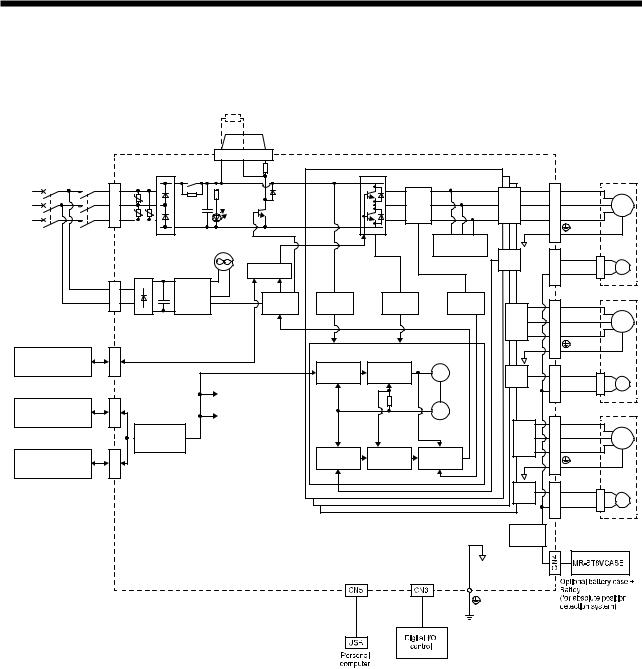
1.2 Function block diagram
The function block diagram of this servo is shown below.
MCCB
(Note 2) Power supply
STO switch
Controller or servo amplifier
Servo amplifier or cap
|
|
|
|
|
|
Regenerative |
|
|
|
|
||
|
|
|
|
|
|
option |
|
|
|
|
|
|
|
|
|
|
|
|
P+ |
C |
D |
|
|
|
|
|
|
|
|
|
|
CNP2 |
|
|
|
|
|
|
|
|
|
|
|
|
|
|
Built-in |
|
|
|
|
|
|
|
|
|
|
|
|
regenerative |
TRM(A) |
|
|
|
MC |
L1 |
|
|
|
|
|
|
resistor |
|
|
|
|
|
|
|
|
|
|
|
|
|
|
|
||
|
|
|
|
|
Regene- |
|
|
|
|
|
||
CNP1 |
|
U |
U |
|
+ |
|
|
Current |
A-axis |
|||
L3 U |
|
TR |
|
|
|
|||||||
|
L2 |
|
|
|
rative |
|
|
|||||
|
|
|
|
|
|
|
|
|
|
detector |
output |
|
|
|
|
|
|
CHARGE |
|
|
|
|
|
|
|
|
|
|
|
|
|
lamp |
|
|
|
|
Dynamic |
|
|
|
|
|
|
Cooling fan |
|
|
|
|
|
brake circuit (A) |
A-axis |
|
|
|
|
|
|
|
|
|
|
|
||
|
|
|
|
|
(Note 1) |
|
STO circuit |
|
|
|
F/B |
|
|
|
|
|
|
|
|
|
|
|
|
||
CNP2 |
L11 |
|
|
Control |
|
|
|
|
|
|
|
|
L21 |
|
+ |
circuit |
|
|
Base |
|
|
Current |
|
||
|
power |
|
|
Overvoltage |
Overcurrent |
|
||||||
|
|
|
|
detection |
|
|||||||
|
|
|
|
|
supply |
|
|
amplifier |
|
(A) |
(A) |
B-axis |
|
|
|
|
|
|
|
|
|
|
|
|
|
|
|
|
|
|
|
|
|
|
|
|
|
output |
CN8 |
|
|
|
|
|
|
|
|
Control (A-axis) |
|
Virtual |
|
|
|
|
|
|
|
|
|
|
motor |
|
||
|
|
|
|
|
|
|
|
|
|
|
||
|
|
|
|
|
|
|
|
Model position |
Model speed |
|
B-axis |
|
|
|
|
|
|
|
|
|
|
|
|||
|
|
|
|
|
|
|
|
|
control (A) |
control (A) |
|
|
|
|
|
|
|
|
|
|
|
|
F/B |
||
|
|
|
|
|
|
|
|
|
|
|
|
|
CN1A |
|
|
|
|
|
Control (B-axis) |
|
|
|
|
||
|
|
|
|
|
Control (C-axis) |
|
|
Virtual |
|
|||
|
|
|
|
|
|
|
|
|
||||
|
|
|
|
|
|
|
|
|
|
|
|
|
|
|
|
|
I/F |
|
|
|
|
|
|
encoder |
C-axis |
|
|
|
|
Control |
|
|
|
|
|
|
|
output |
CN1B |
|
|
|
|
|
|
|
|
Actual position |
Actual speed |
Current |
|
|
|
|
|
|
|
|
|
control (A) |
control (A) |
control (A) |
|
|
|
|
|
|
|
|
|
|
|
|
|||
|
|
|
|
|
|
|
|
|
|
|
|
C-axis |
|
|
|
|
|
|
|
|
|
|
|
|
F/B |
|
U |
A-axis Servo motor |
|
CNP3A |
V |
M |
|
W |
|||
|
|||
|
|
CN2A |
|
E |
|
|
|
||
|
U |
B-axis Servo motor |
|
CNP3B |
V |
M |
|
W |
|||
|
|||
|
|
||
CN2B |
|
E |
|
|
|
|
U |
C-axis Servo motor |
|
CNP3C |
V |
M |
|
W |
|||
|
|||
|
|
||
CN2C |
|
E |
|
|
|
Step-down
circuit
Note 1. The MR-J4W2-22B has no cooling fan.
2.For 1-phase 200 V AC to 240 V AC, connect the power supply to L1 and L3. Leave L2 open. For the power supply specifications, refer to section 1.3.
1 - 2

1. FUNCTIONS AND CONFIGURATION
1.3 Servo amplifier standard specifications 1.3.1 Integrated 2-axis servo amplifier
Model MR-J4W2- |
|
22B |
|
44B |
|
77B |
|
1010B |
|||
|
|
Rated voltage |
|
|
|
3-phase 170 V AC |
|
|
|
||
Output |
|
Rated current |
|
1.5 |
|
2.8 |
|
5.8 |
|
6.0 |
|
|
(each axis) |
[A] |
|
|
|
||||||
|
|
|
|
|
|
|
|
|
|||
|
|
Power supply |
|
3-phase or 1-phase 200 V AC to 240 V AC, 50/60 Hz |
|
3-phase 200 V AC to |
|||||
|
|
/Frequency |
|
|
240 V AC, 50/60 Hz |
||||||
|
|
|
|
|
|
|
|
|
|||
|
|
Rated current |
[A] |
2.9 |
|
5.2 |
|
7.5 |
|
9.8 |
|
Main circuit |
|
Permissible voltage |
|
3-phase or 1-phase 170 V AC to 264 V AC |
|
|
3-phase 170 V AC to |
||||
|
fluctuation |
|
|
|
|
264 V AC |
|||||
power supply |
|
|
|
|
|
|
|
|
|||
|
Permissible frequency |
|
|
|
|
|
|
|
|||
input |
|
|
|
Within ±5% |
|
|
|
||||
|
fluctuation |
|
|
|
|
|
|
||||
|
|
|
|
|
|
|
|
|
|
||
|
|
Power supply |
|
|
|
Refer to section 10.2. |
|
|
|||
|
|
capacity |
[kVA] |
|
|
|
|
||||
|
|
|
|
|
|
|
|
|
|||
|
|
Inrush current |
[A] |
|
|
Refer to section 10.5. |
|
|
|||
|
|
Power supply |
|
|
|
1-phase 200 V AC to 240 V AC, 50/60 Hz |
|
|
|||
|
|
/Frequency |
|
|
|
|
|
||||
|
|
|
|
|
|
|
|
|
|
||
|
|
Rated current |
[A] |
|
0.4 |
|
|
|
|||
Control circuit |
|
Permissible voltage |
|
|
1-phase 170 V AC to 264 V AC |
|
|
||||
|
fluctuation |
|
|
|
|
|
|||||
power supply |
|
|
|
|
|
|
|
|
|
|
|
|
Permissible frequency |
|
|
|
|
|
|
|
|||
input |
|
|
|
Within ±5% |
|
|
|
||||
|
fluctuation |
|
|
|
|
|
|
||||
|
|
|
|
|
|
|
|
|
|
||
|
|
Power consumption |
|
55 |
|
|
|
||||
|
|
|
|
[W] |
|
|
|
|
|||
|
|
|
|
|
|
|
|
|
|
|
|
|
|
Inrush current |
[A] |
|
|
Refer to section 10.5. |
|
|
|||
Interface |
|
Voltage/Frequency |
|
|
24 V DC ± 10% |
|
|
|
|||
|
Power supply |
|
|
|
|
|
|
|
|
||
power supply |
|
|
|
|
0.35 A (Note 1) |
|
|
|
|||
|
capacity |
|
|
|
|
|
|
||||
|
|
|
|
|
|
|
|
|
|
||
|
|
Reusable regenerative |
17 |
|
21 |
|
|
44 |
|||
|
|
energy (Note 2) |
[J] |
|
|
|
|||||
|
|
|
|
|
|
|
|
|
|||
|
|
Moment of inertia J |
|
|
|
|
|
|
|
||
|
|
equivalent to the |
|
|
|
|
|
|
|
||
|
|
permissible charging |
3.45 |
|
4.26 |
|
|
8.92 |
|||
|
|
amount (Note 3) |
|
|
|
|
|
|
|
||
Capacitor |
|
[× 10-4 kg • m2] |
|
|
|
|
|
|
|
||
regeneration |
|
Mass |
|
LM-H3 |
3.8 |
|
4.7 |
|
|
9.8 |
|
|
|
equivalent to |
|
|
|
|
|
|
|
|
|
|
|
the |
|
LM-F |
|
|
|
|
|
|
|
|
|
permissible |
|
|
|
|
|
|
|
|
|
|
|
|
LM-K2 |
8.5 |
|
10.5 |
|
|
22.0 |
||
|
|
charging |
|
|
|
|
|||||
|
|
|
LM-U2 |
|
|
|
|
|
|
|
|
|
|
amount |
|
|
|
|
|
|
|
|
|
|
|
(Note 4) [kg] |
|
|
|
|
|
|
|
|
|
Control method |
|
|
|
|
|
Sine-wave PWM control, current control method |
|||||
Built-in regenerative resistance |
[W] |
|
20 |
|
|
100 |
|||||
Dynamic brake |
|
|
|
|
|
Built-in |
|
|
|
||
Fully-closed loop control |
|
|
|
Available in the future |
|
|
|||||
Load-side encoder interface |
|
|
|
Mitsubishi serial interface(Note 6) |
|
|
|||||
Communication |
|
USB |
|
Connection to a personal computer or others (MR Configurator2-compatible) |
|||||||
function |
|
|
|
|
|
|
|
|
|
|
|
|
|
|
|
|
Overcurrent protection, regenerative overvoltage shut-off, overload shut-off (electronic |
||||||
Protective functions |
|
thermal), servo motor overheat protection, encoder error protection, regenerative error |
|||||||||
|
protection, undervoltage protection, instantaneous power failure protection, overspeed |
||||||||||
|
|
|
|
|
|||||||
|
|
|
|
|
|
|
protection, and error excessive protection |
|
|
||
1 - 3

1. FUNCTIONS AND CONFIGURATION
Model MR-J4W2- |
|
22B |
|
44B |
|
77B |
|
1010B |
||
Safety function |
|
|
|
|
STO (IEC/EN 61800-5-2)(Note 7) |
|
||||
|
|
Standards certified by |
EN ISO 13849-1 PL d (category 3), EN 61508 SIL 2, EN 62061 SIL CL2 |
|||||||
|
|
CB(Note 8) |
|
|||||||
|
|
|
|
|
|
|
|
|
|
|
Safety |
|
Response |
|
|
|
8 ms or less (STO input off |
energy shut off) |
|
||
performance |
|
performance |
|
|
|
|
||||
|
|
|
|
|
|
|
|
|
||
|
|
(Note 5) Test pulse |
|
|
Test pulse interval: 1 Hz to 25 Hz |
|
||||
|
|
input (STO) |
|
|
|
Test pulse off time: Up to 1 ms |
|
|||
|
|
|
|
|
|
LVD: EN 61800-5-1 |
|
|||
Compliance |
|
CE marking |
|
|
|
EMC: EN 61800-3 |
|
|||
to standards |
|
|
|
|
|
MD: EN ISO 13849-1, EN 61800-5-2, EN 62061 |
|
|||
|
|
UL standard |
|
|
|
UL 508C |
|
|
|
|
Structure (IP rating) |
|
Natural cooling, open |
Force cooling, open (IP20) |
|
||||||
|
(IP20) |
|
|
|||||||
|
|
|
|
|
|
|
|
|
|
|
Close mounting |
|
|
|
|
Possible |
|
|
|
||
|
|
Ambient |
Operation |
|
|
0 °C to 55 °C (non-freezing) |
|
|||
|
|
temperature |
Storage |
|
|
-20 °C to 65 °C (non-freezing) |
|
|||
|
|
Ambient |
Operation |
|
|
90% RH or less (non-condensing) |
|
|||
Environment |
|
humidity |
Storage |
|
|
|
||||
|
|
|
|
|
|
|
|
|||
|
|
Ambience |
|
Indoors (no direct sunlight), free from corrosive gas, flammable gas, oil mist, dust, and dirt |
||||||
|
|
Altitude |
|
|
|
Max. 1000 m above sea level |
|
|||
|
|
Vibration |
|
|
5.9 m/s2 or less at 10 Hz to 55 Hz (directions of X, Y and Z axes) |
|
||||
Mass |
|
[kg] |
|
1.5 |
|
2.0 |
|
|||
Note 1. 0.35 A is the value applicable when all I/O signals are used. The current capacity can be decreased by reducing the number of I/O points.
2.Regenerative energy is generated under the following conditions.
Rotary servo motor: Regenerative energy is generated when the machine, whose moment of inertia is equivalent to the permissible charging amount, decelerates from the rated speed to stop.
Linear servo motor: Regenerative energy is generated when the machine, whose mass is equivalent to the permissible charging amount, decelerates from the maximum speed to stop.
Direct drive motor: Regenerative energy is generated when the machine, whose moment of inertia is equivalent to the permissible charging amount, decelerates from the rated speed to stop.
3.Moment of inertia when the motor decelerates from the rated speed to stop Moment of inertia for two axes when two motors decelerate simultaneously
Moment of inertia for each axis when multiple motors do not decelerate simultaneously The values also apply to the direct drive motor.
4.Mass when the machine decelerates from the maximum speed to stop The primary-side (coil) mass is included.
Mass for two axes when two motors decelerate simultaneously
Mass for each axis when multiple motors do not decelerate simultaneously
5.This function diagnoses malfunction of contacts including an external circuit by shortly turning off signals from a controller to the servo amplifier at a constant period while input signals of the servo amplifier are on.
6.Not compatible with pulse train interface (A/B/Z-phase differential output type).
7.STO is common for all axes.
8.Some of the models are under application.
1 - 4

1. FUNCTIONS AND CONFIGURATION
1.3.2 Integrated 3-axis servo amplifier
Model MR-J4W3- |
|
222B |
|
444B |
|||
|
|
Rated voltage |
|
|
3-phase 170 V AC |
||
Output |
|
Rated current |
|
1.5 |
|
2.8 |
|
|
(each axis) |
[A] |
|
||||
|
|
|
|
|
|||
|
|
Power supply |
|
3-phase or 1-phase 200 V AC to 240 V AC, 50/60 Hz |
|||
|
|
/Frequency |
|
||||
|
|
|
|
|
|
||
|
|
Rated current |
[A] |
4.3 |
|
7.8 |
|
Main circuit |
|
Permissible voltage |
3-phase or 1-phase 170 V AC to 264 V AC, 50/60 Hz |
||||
|
fluctuation |
|
|||||
power supply |
|
|
|
|
|
||
|
Permissible frequency |
|
|
|
|||
input |
|
|
Within ±5% |
||||
|
fluctuation |
|
|
||||
|
|
|
|
|
|
||
|
|
Power supply |
|
|
Refer to section 10.2. |
||
|
|
capacity |
[kVA] |
|
|||
|
|
|
|
|
|||
|
|
Inrush current |
[A] |
|
Refer to section 10.5. |
||
|
|
Power supply |
|
|
1-phase 200 V AC to 240 V AC, 50/60 Hz |
||
|
|
/Frequency |
|
|
|||
|
|
|
|
|
|
||
|
|
Rated current |
[A] |
|
0.4 |
||
Control circuit |
|
Permissible voltage |
|
1-phase 170 V AC to 264 V AC |
|||
|
fluctuation |
|
|
||||
power supply |
|
|
|
|
|
|
|
|
Permissible frequency |
|
|
|
|||
input |
|
|
Within ±5% |
||||
|
fluctuation |
|
|
||||
|
|
|
|
|
|
||
|
|
Power consumption |
|
55 |
|||
|
|
|
|
[W] |
|
||
|
|
|
|
|
|
|
|
|
|
Inrush current |
[A] |
|
Refer to section 10.5. |
||
Interface |
|
Voltage/Frequency |
|
24 V DC ± 10% |
|||
|
Power supply |
|
|
|
|
||
power supply |
|
|
|
0.45 A (Note 1) |
|||
|
capacity |
|
|
||||
|
|
|
|
|
|
||
|
|
Reusable regenerative |
21 |
|
30 |
||
|
|
energy (Note 2) |
[J] |
|
|||
|
|
|
|
|
|||
|
|
Moment of inertia J |
|
|
|
||
|
|
equivalent to the |
|
|
|
||
|
|
permissible charging |
4.26 |
|
6.08 |
||
|
|
amount (Note 3) |
|
|
|
||
Capacitor |
|
[× 10-4 kg • m2] |
|
|
|
||
regeneration |
|
Mass |
|
LM-H3 |
4.7 |
|
6.7 |
|
|
equivalent to |
|
|
|
|
|
|
|
the |
|
LM-F |
|
|
|
|
|
permissible |
|
|
|
|
|
|
|
|
LM-K2 |
10.5 |
|
15.0 |
|
|
|
charging |
|
|
|||
|
|
|
LM-U2 |
|
|
|
|
|
|
amount |
|
|
|
|
|
|
|
(Note 4) [kg] |
|
|
|
|
|
Control method |
|
|
|
Sine-wave PWM control, current control method |
|||
Built-in regenerative resistance |
[W] |
30 |
|
100 |
|||
Dynamic brake |
|
|
|
|
Built-in |
||
Fully-closed loop control |
|
|
Not compatible |
||||
Communication |
|
USB |
|
Connection to a personal computer or others (MR Configurator2-compatible) |
|||
function |
|
|
|
|
|
|
|
|
|
|
|
|
Overcurrent protection, regenerative overvoltage shut-off, overload shut-off (electronic |
||
Protective functions |
|
thermal), servo motor overheat protection, encoder error protection, regenerative error |
|||||
|
protection, undervoltage protection, instantaneous power failure protection, overspeed |
||||||
|
|
|
|
|
|||
|
|
|
|
|
|
protection, and error excessive protection |
|
1 - 5

1. FUNCTIONS AND CONFIGURATION
Model MR-J4W3- |
|
222B |
|
444B |
||
Safety function |
|
|
|
STO (IEC/EN 61800-5-2) (Note 6) |
||
|
|
Standards certified by |
EN ISO 13849-1 PL d (category 3), EN 61508 SIL 2, EN 62061 SIL CL2 |
|||
|
|
CB (Note 7) |
|
|||
|
|
|
|
|
|
|
Safety |
|
Response |
|
8 ms or less (STO input off energy shut off) |
||
performance |
|
performance |
|
|||
|
|
|
|
|
||
|
|
(Note 5) Test pulse |
|
Test pulse interval: 1 Hz to 25 Hz |
||
|
|
input (STO) |
|
|
Test pulse off time: Up to 1 ms |
|
|
|
|
|
|
LVD: EN 61800-5-1 |
|
Compliance |
|
CE marking |
|
|
EMC: EN 61800-3 |
|
to standards |
|
|
|
MD: EN ISO 13849-1, EN 61800-5-2, EN 62061 |
||
|
|
UL standard |
|
|
UL 508C |
|
Structure (IP rating) |
|
|
Force cooling, open (IP20) |
|||
Close mounting |
|
|
|
Possible |
||
|
|
Ambient |
Operation |
|
0 °C to 55 °C (non-freezing) |
|
|
|
temperature |
Storage |
|
-20 °C to 65 °C (non-freezing) |
|
|
|
Ambient |
Operation |
|
90% RH or less (non-condensing) |
|
Environment |
|
humidity |
Storage |
|
||
|
|
|
|
|||
|
|
Ambience |
|
Indoors (no direct sunlight), free from corrosive gas, flammable gas, oil mist, dust, and dirt |
||
|
|
Altitude |
|
|
Max. 1000 m above sea level |
|
|
|
Vibration |
|
5.9 m/s2 or less at 10 Hz to 55 Hz (directions of X, Y and Z axes) |
||
Mass |
|
[kg] |
|
1.9 |
||
Note 1. 0.45 A is the value applicable when all I/O signals are used. The current capacity can be decreased by reducing the number of I/O points.
2.Regenerative energy is generated under the following conditions.
Rotary servo motor: Regenerative energy is generated when the machine, whose moment of inertia is equivalent to the permissible charging amount, decelerates from the rated speed to stop.
Linear servo motor: Regenerative energy is generated when the machine, whose mass is equivalent to the permissible charging amount, decelerates from the maximum speed to stop.
Direct drive motor: Regenerative energy is generated when the machine, whose moment of inertia is equivalent to the permissible charging amount, decelerates from the rated speed to stop.
3.Moment of inertia when the machine decelerates from the rated speed to stop Moment of inertia for three axes when three motors decelerate simultaneously Moment of inertia for each axis when multiple motors do not decelerate simultaneously The values also apply to the direct drive motor.
4.Mass when the machine decelerates from the maximum speed to stop The primary-side (coil) mass is included.
Mass for three axes when three motors decelerate simultaneously
Mass for each axis when multiple motors do not decelerate simultaneously
5.This function diagnoses malfunction of contacts including an external circuit by shortly turning off signals from a controller to the servo amplifier at a constant period while input signals of the servo amplifier are on.
6.STO is common for all axes.
7.Some of the models are under application.
1 - 6

1. FUNCTIONS AND CONFIGURATION
1.3.3 Combinations of servo amplifier and servo motor
(1) With MR-J4W2-B servo amplifier
Servo amplifier |
Rotary servo motor |
Linear servo motor |
Direct drive motor |
|
|
(primary side) |
|
MR-J4W2-22B |
HG-KR053, HG-KR13, |
LM-U2PAB-05M-0SS0 |
TM-RFM002C20 |
|
HG-KR23 |
LM-U2PBB-07M-1SS0 |
|
|
HG-MR053, HG-MR13, |
|
|
|
HG-MR23 |
|
|
MR-J4W2-44B |
HG-KR053, HG-KR13, |
LM-H3P2A-07P-BSS0 |
TM-RFM002C20 |
|
HG-KR23, HG-KR43 |
LM-H3P3A-12P-CSS0 |
TM-RFM004C20 |
|
HG-MR053, HG-MR13, |
LM-K2P1A-01M-2SS1 |
|
|
HG-MR23, HG-MR43 |
LM-U2PAB-05M-0SS0 |
|
|
LM-U2PAD-10M-0SS0 |
|
|
|
|
|
|
|
|
LM-U2PAF-15M-0SS0 |
|
|
|
LM-U2PBB-07M-1SS0 |
|
MR-J4W2-77B |
HG-KR43, HG-KR73 |
LM-H3P2A-07P-BSS0 |
TM-RFM004C20 |
|
HG-MR43, HG-MR73 |
LM-H3P3A-12P-CSS0 |
TM-RFM006C20 |
|
HG-SR51, HG-SR52 |
LM-H3P3B-24P-CSS0 |
TM-RFM006E20 |
|
|
LM-H3P3C-36P-CSS0 |
TM-RFM012E20 |
|
|
LM-H3P7A-24P-ASS0 |
TM-RFM012G20 |
|
|
LM-K2P1A-01M-2SS1 |
TM-RFM040J10 |
|
|
LM-K2P2A-02M-1SS1 |
|
|
|
LM-U2PAD-10M-0SS0 |
|
|
|
LM-U2PAF-15M-0SS0 |
|
|
|
LM-U2PBD-15M-1SS0 |
|
|
|
LM-U2PBF-22M-1SS0 |
|
MR-J4W2-1010B |
HG-KR43, HG-KR73 |
LM-H3P2A-07P-BSS0 |
TM-RFM004C20 |
|
HG-MR43, HG-MR73 |
LM-H3P3A-12P-CSS0 |
TM-RFM006C20 |
|
HG-SR51, HG-SR81, |
LM-H3P3B-24P-CSS0 |
TM-RFM006E20 |
|
HG-SR52, HG-SR102 |
LM-H3P3C-36P-CSS0 |
TM-RFM012E20 |
|
LM-H3P7A-24P-ASS0 |
TM-RFM018E20 |
|
|
|
||
|
|
LM-K2P1A-01M-2SS1 |
TM-RFM012G20 |
|
|
LM-K2P2A-02M-1SS1 |
TM-RFM040J10 |
|
|
LM-U2PAD-10M-0SS0 |
|
|
|
LM-U2PAF-15M-0SS0 |
|
|
|
LM-U2PBD-15M-1SS0 |
|
|
|
LM-U2PBF-22M-1SS0 |
|
(2) With MR-J4W3-B servo amplifier
Servo amplifier |
Rotary servo motor |
Linear servo motor |
Direct drive motor |
|
|
(primary side) |
|
MR-J4W3-222B |
HG-KR053, HG-KR13, |
LM-U2PAB-05M-0SS0 |
TM-RFM002C20 |
|
HG-KR23 |
LM-U2PBB-07M-1SS0 |
|
|
HG-MR053, HG-MR13, |
|
|
|
HG-MR23 |
|
|
MR-J4W3-444B |
HG-KR053, HG-KR13, |
LM-H3P2A-07P-BSS0 |
TM-RFM002C20 |
|
HG-KR23, HG-KR43 |
LM-H3P3A-12P-CSS0 |
TM-RFM004C20 |
|
HG-MR053, HG-MR13, |
LM-K2P1A-01M-2SS1 |
|
|
HG-MR23, HG-MR43 |
LM-U2PAB-05M-0SS0 |
|
|
LM-U2PAD-10M-0SS0 |
|
|
|
|
|
|
|
|
LM-U2PAF-15M-0SS0 |
|
|
|
LM-U2PBB-07M-1SS0 |
|
1 - 7
1. FUNCTIONS AND CONFIGURATION
1.4 Function list
The following table lists the functions of this servo. For details of the functions, refer to the reference field.
Function |
Description |
Detailed |
|
explanation |
|||
|
|
||
Position control mode |
This servo is used as a position control servo. |
|
|
Speed control mode |
This servo is used as a speed control servo. |
|
|
Torque control mode |
This servo is used as a torque control servo. |
|
|
High-resolution encoder |
High-resolution encoder of 4194304 pulses/rev is used as the encoder of the rotary |
|
|
servo motor compatible with the MELSERVO-J4 series. |
|
||
|
|
||
Absolute position detection |
Merely setting a home position once makes home position return unnecessary at |
Chapter 12 |
|
system |
every power-on. |
||
|
|||
Gain switching function |
Using an input device or gain switching conditions (including the servo motor |
Section 7.2 |
|
speed) switches gains. |
|||
|
|
||
Advanced vibration |
This function suppresses vibration at the arm end or residual vibration of the |
Section 7.1.5 |
|
suppression control II |
machine. |
||
|
|||
Adaptive filter II |
Servo amplifier detects mechanical resonance and sets filter characteristics |
Section 7.1.2 |
|
automatically to suppress mechanical vibration. |
|||
|
|
||
Low-pass filter |
Suppresses high-frequency resonance which occurs as servo system response is |
Section 7.1.4 |
|
increased. |
|||
|
|
||
|
Analyzes the frequency characteristic of the mechanical system by simply |
|
|
Machine analyzer function |
connecting a MR Configurator2 installed personal computer and servo amplifier. |
|
|
|
MR Configurator2 is necessary for this function. |
|
|
Robust filter |
This function provides better disturbance response in case low response level that |
[Pr. PE41] |
|
load to motor inertia ratio is high for such as roll send axes. |
|||
|
|
||
Slight vibration suppression |
Suppresses vibration of ±1 pulse produced at a servo motor stop. |
[Pr. PB24] |
|
control |
|
||
|
|
||
Auto tuning |
Automatically adjusts the gain to optimum value if load applied to the servo motor |
Chapter 6 |
|
shaft varies. |
|||
|
|
||
Regenerative option |
Used when the built-in regenerative resistor of the servo amplifier does not have |
Section 11.2 |
|
sufficient regenerative capability for the regenerative power generated. |
|||
|
|
||
Alarm history clear |
Alarm history is cleared. |
[Pr. PC21] |
|
Output signal selection |
The pins that output the output devices, including ALM (Malfunction) and DB |
[Pr. PD07] to |
|
(Device settings) |
(Dynamic brake interlock), can be assigned to certain pins of the CN3 connectors. |
[Pr. PD09] |
|
Output signal (DO) forced |
Output signal can be forced on/off independently of the servo status. |
Section 4.5.1 (1) |
|
output |
Use this function for output signal wiring check and others. |
(d) |
|
|
Jog operation, positioning operation, motor-less operation, DO forced output, and |
|
|
Test operation mode |
program operation |
Section 4.5 |
|
|
MR Configurator2 is necessary for this function. |
|
|
MR Configurator2 |
Using a personal computer, you can perform the parameter setting, test operation, |
Section 11.4 |
|
monitoring, and others. |
|||
|
|
||
|
One click on a certain button on MR Configurator2 adjusts the gains of the servo |
|
|
One-touch adjustment |
amplifier. |
Section 6.2 |
|
|
MR Configurator2 is necessary for this function. |
|
|
|
This function makes the equipment continue operating even under the condition |
|
|
Tough drive function |
that an alarm occurs. |
Section 7.3 |
|
The tough drive function includes two types: the vibration tough drive and the |
|||
|
|
||
|
instantaneous power failure tough drive. |
|
|
|
This function continuously monitors the servo status and records the status |
|
|
|
transition before and after an alarm for a fixed period of time. You can check the |
|
|
|
recorded data on the drive recorder window on MR Configurator2 by clicking the |
|
|
Drive recorder function |
"Graph" button. |
[Pr. PA23] |
|
However, the drive recorder will not operate on the following conditions. |
|||
|
|
||
|
1. You are using the graph function of MR Configurator2. |
|
|
|
2. You are using the machine analyzer function. |
|
|
|
3. [Pr. PF21] is set to "-1". |
|
|
STO function |
This function is a safety function that complies with IEC/EN 61800-5-2. You can |
Chapter 13 |
|
create a safety system for the equipment easily. |
|||
|
|
1 - 8
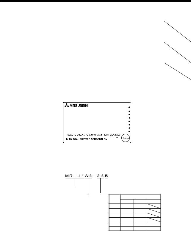
1. FUNCTIONS AND CONFIGURATION
Function |
Description |
Detailed |
|
explanation |
|||
|
|
||
|
You can check the cumulative energization time and the number of on/off times of |
|
|
Servo amplifier life diagnosis |
the inrush relay. Before the parts of the servo amplifier, including a capacitor and |
|
|
relay, malfunction, this function is useful for finding out the time for their |
|
||
function |
|
||
replacement. |
|
||
|
|
||
|
MR Configurator2 is necessary for this function. |
|
|
|
This function calculates the power running and the regenerative power from the |
|
|
Power monitoring function |
data, including the speed and current, in the servo amplifier. For the SSCNET III/H |
|
|
system, MR Configurator2 can display the data, including the power consumption. |
|
||
|
Since the servo amplifier can send the data to a motion controller, you can analyze |
|
|
|
the data and display the data on a display. |
|
|
|
From the data in the servo amplifier, this function estimates the friction and |
|
|
Machine diagnostic function |
vibrational component of the drive system in the equipment and recognizes an |
|
|
error in the machine parts, including a ball screw and bearing. |
|
||
|
|
||
|
MR Configurator2 is necessary for this function. |
|
1.5 Model designation
(1) Rating plate
|
|
|
|
|
|
|
|
|
AC SERVO |
|
|
|
|
|
|
|
|
|
|
|
|
|
|
|
|
SER.S21001001 |
|
|
|
|
|
6HULDO QXPEHU |
|
|
|
|
|
|
|
|
|
|
|
|
|
|
|
|||
MODEL MR-J4W3-222B |
|
|
|
|
|
0RGHO |
||||||||||
|
|
|
|
|
||||||||||||
|
POWER: |
200W×3 (A, B, C) |
|
|
|
|
|
&DSDFLW\ |
||||||||
|
|
|
|
|
|
|||||||||||
|
|
INPUT : 3AC/AC200-240V 4.3A/7.5A 50/60Hz |
|
|
|
|
|
$SSOLFDEOH SRZHU VXSSO\ |
||||||||
|
|
|
|
|
|
|
||||||||||
|
OUTPUT: 3PH170V 0-360Hz 1.5A×3 (A, B, C) |
|
|
|
|
|
5DWHG RXWSXW FXUUHQW |
|||||||||
|
|
|
|
|
|
|||||||||||
|
STD.: IEC/EN61800-5-1 MAN.: IB(NA)0300176 |
|
|
|
|
|
6WDQGDUG 0DQXDO QXPEHU |
|||||||||
|
|
|
|
|
|
|||||||||||
|
Max. Surrounding Air Temp.: 55°C |
|
|
|
|
|
$PELHQW WHPSHUDWXUH |
|||||||||
|
|
|
|
|
|
|||||||||||
|
IP20 (Except for fan finger guard) |
|
|
|
|
|
,3 UDWLQJ |
|||||||||
|
|
|
|
|
|
|||||||||||
|
|
|
|
|
|
|
|
|
|
|
|
|
|
|
|
7KH \HDU DQG PRQWK RI |
|
|
|
|
|
|
|
|
|
|
|
|
|
|
|
|
|
|
|
|
|
|
|
|
|
|
|
|
|
|
|
|
|
|
|
TOKYO 100-8310, JAPAN |
MADE IN JAPAN |
|
|
|
|
|
|
PDQXIDFWXUH |
|||||||
|
|
|
|
|||||||||||||
|
|
|
|
|
|
|
|
|
|
|
|
|
||||
|
|
|
|
|
|
|
|
|
|
|
|
|
|
|
|
|
(2)Model
The following describes what each block of a model name indicates. Not all combinations of the symbols are available.
Series
Number of axes
Symbol |
Number |
of axes |
|
W2 |
2 |
W3 |
3 |
 SSCNETIII/H interface
Rated output |
|
|
|
Symbol |
Rated output [kW] |
||
A-axis |
B-axis C-axis |
||
22 |
0.2 |
0.2 |
|
44 |
0.4 |
0.4 |
|
77 |
0.75 |
0.75 |
|
1010 |
1 |
1 |
|
222 |
0.2 |
0.2 |
0.2 |
444 |
0.4 |
0.4 |
0.4 |
1 - 9
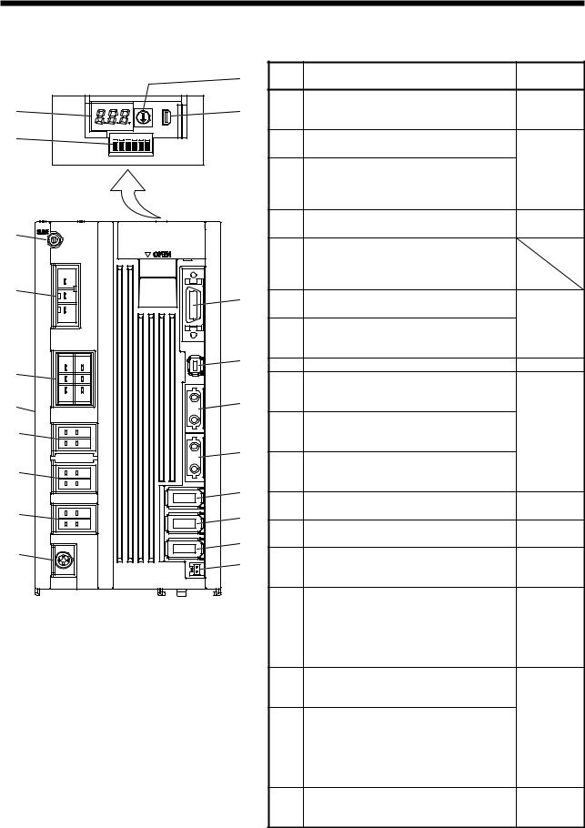
1. FUNCTIONS AND CONFIGURATION |
|
|
|||
1.6 Parts identification |
|
|
|
|
|
|
(2) |
No. |
Name/Application |
Detailed |
|
|
explanation |
||||
|
|
|
|
||
(1) |
(4) |
|
Display |
|
|
(1) |
The 3-digit, seven-segment LED shows the |
Section 4.3.2 |
|||
|
|
|
servo status and the alarm number. |
|
|
(3) |
|
(2) |
Axis selection rotary switch (SW1) |
|
|
|
|
Used to set the axis No. of servo amplifier. |
|
||
|
|
|
|
||
|
|
|
Control axis setting switch (SW2) |
Section 4.3 |
|
|
|
|
The test operation switch, the control axis |
||
|
|
(3) |
|
||
|
|
deactivation setting switch, and the auxiliary |
|
||
|
|
|
|
||
|
|
|
axis number setting switch are available. |
|
|
|
|
(4) |
USB communication connector (CN5) |
Section 11.4 |
|
(5) |
|
Connect with the personal computer. |
|||
|
|
|
|||
|
|
|
Charge lamp |
|
|
|
|
(5) |
Lit to indicate that the main circuit is charged. |
|
|
|
|
While this lamp is lit, do not reconnect the |
|
||
|
|
|
|
||
(6) |
|
|
cables. |
|
|
(13) |
|
Main circuit power supply connector (CNP1) |
|
||
|
(6) |
|
|||
|
|
Connect the input power supply. |
|
||
|
|
|
Section 3.1 |
||
|
|
|
Control circuit power supply connector (CNP2) |
||
|
|
|
Section 3.3 |
||
|
|
(7) |
Connect the control circuit power supply or |
||
|
|
|
|||
|
(14) |
|
regenerative option. |
|
|
|
(8) |
Rating plate |
Section 1.5 |
||
(7) |
|
||||
|
|
A-axis servo motor power supply connector |
|
||
|
|
|
|
||
|
(15) |
(9) |
(CNP3A) |
|
|
(8) |
|
Connect the A-axis servo motor. |
|
||
Side |
|
|
B-axis servo motor power supply connector |
Section 3.1 |
|
(9)view |
|
|
|||
|
(10) |
(CNP3B) |
|||
|
(16) |
|
Connect the B-axis servo motor. |
Section 3.3 |
|
|
|
|
|||
|
|
C-axis servo motor power supply connector |
|
||
(10) |
|
|
|
||
|
(11) |
(CNP3C) (Note) |
|
||
|
(17) |
|
Connect the C-axis servo motor. |
|
|
|
|
Protective earth (PE) terminal |
|
||
|
|
(12) |
Section 3.11 |
||
(11) |
(18) |
Grounding terminal |
|||
|
|
||||
|
|
I/O signal connector (CN3) |
Section 3.2 |
||
|
|
(13) |
|||
|
(19) |
Used to connect digital I/O signals. |
Section 3.4 |
||
(12) |
|
||||
(20) |
|
STO input signal connector (CN8) |
|
||
|
(14) |
Used to connect MR-J3-D05 safety logic unit |
Chapter 13 |
||
|
|
||||
|
|
|
and external safety relay. |
|
|
|
|
|
SSCNET III cable connector (CN1A) |
|
|
(15)Used to connect the servo system controller or
the previous axis servo amplifier. |
Section 3.2 |
SSCNET III cable connector (CN1B) |
Section 3.4 |
(16)Used to connect the next axis servo amplifier. For the final axis, put a cap.
A-axis encoder connector (CN2A)
(17)Used to connect the A-axis servo motor encoder.
|
B-axis encoder connector (CN2B) |
Section 3.1 |
|
(18) |
Used to connect the B-axis servo motor |
||
Section 3.3 |
|||
|
encoder. |
||
|
|
||
|
C-axis encoder connector (CN2C) (Note) |
|
(19)Used to connect the C-axis servo motor encoder.
(20) |
Battery connector (CN4) |
Section 11.3 |
|
Used to connect the battery unit for absolute |
|||
Chapter 12 |
|||
|
position data backup. |
||
|
|
Note. This figure shows the MR-J4 3-axis servo amplifier.
1 - 10
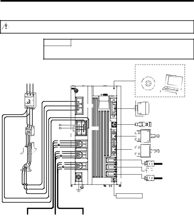
1. FUNCTIONS AND CONFIGURATION
1.7 Configuration including auxiliary equipment
CAUTION Connecting an inappropriate servo motor to the CNP3A, CNP3B, CNP3C, CN2A, CN2B, or CN2C will cause an unexpected operation or an alarm.
POINT
 Equipment other than the servo amplifier and servo motor are optional or recommended products.
Power supply R S T
Molded case
No-fuse breaker circuit breaker
(MCCB) or fuse
(MCCB) or fuse
Magnetic contactor (MC)
Power factor improving  reactor
  (FR-HAL)

Line noise filter (FR-BSF01) 
L21
L11
A-axis servo motor
|
|
Personal |
|
MR Configurator2 |
computer |
CN5 |
|
|
|
|
|
(under the cover) |
|
|
L1 |
|
|
L2 |
CNP1 |
|
L3 |
||
|
||
P+ |
|
|
C |
CNP2 |
|
D (Note 3) |
||
Regenerative |
||
option |
CNP3A |
|
U |
||
|
||
W |
|
|
V |
CNP3B |
|
U |
||
W |
||
V |
CNP3C (Note 1) |
|
|
U |
|
|
W |
|
|
V |
|
CN3 |
|
|
|
|
|
|
I/O signal |
|||||
|
|
|
|
|
|
|
|
|
|
|
|
|
|
|
|
|
|
|
|
|
|||||
CN8 |
|
|
Safety relay or |
|||||||||
|
|
|
|
|
|
|
|
|
|
|
MR-J3-D05 safety logic unit |
|
CN1A |
|
|
|
|
|
|
|
|
Servo system |
|||
|
|
|
|
|
|
|
|
|||||
|
|
|
|
|
|
|
|
|||||
|
|
|
|
controller or Front axis |
||||||||
CN1B |
|
servo amplifier CN1B |
||||||||||
|
||||||||||||
|
Rear servo amplifier |
|||||||||||
|
||||||||||||
|
||||||||||||
|
|
|
|
|
|
|
|
|
|
|
|
|
|
|
|
|
|
|
|
|
|
|
|
|
CN1A or Cap |
|
|
|
|
|
|
|
|
|
|
|
|
|
CN2A |
|
|||||||||||
|
|
|||||||||||
|
|
|||||||||||
CN2B
CN2C (Note 1) 


CN4
(Note 2) Battery unit
A-axis encoder B-axis encoder C-axis encoder
B-axis |
C-axis |
servo motor |
servo motor |
Note 1. For the MR-J4 3-axis servo amplifier
2.The battery unit consists of a battery case (MR-BT6VCASE) and up to 5 batteries (MR-BAT6V1). The battery unit is used in the absolute position detection system. (Refer to chapter 12.)
3.Always connect P+ and D. When using the regenerative option, refer to section 11.2.
1 - 11

)81&7,216$1' &21),*85$7,21
0(02
,167$//$7,21
,167$//$7,21

 :$51,1* 7R SUHYHQW HOHFWULF VKRFN JURXQG HDFK HTXLSPHQW VHFXUHO\
 6WDFNLQJ LQ H[FHVV RI WKH VSHFLILHG QXPEHU RI SURGXFW SDFNDJHV LV QRW DOORZHG
 ,QVWDOO WKH HTXLSPHQW RQ LQFRPEXVWLEOH PDWHULDO ,QVWDOOLQJ LW GLUHFWO\ RU FORVH WR FRPEXVWLEOHV ZLOO OHDG WR D ILUH
 ,QVWDOO WKH VHUYR DPSOLILHU DQG WKH VHUYR PRWRU LQ D ORDG EHDULQJ SODFH LQ DFFRUGDQFH ZLWK WKH ,QVWUXFWLRQ 0DQXDO
 'R QRW JHW RQ RU SXW KHDY\ ORDG RQ WKH HTXLSPHQW 2WKHUZLVH LW PD\ FDXVH LQMXU\
 8VH WKH HTXLSPHQW ZLWKLQ WKH VSHFLILHG HQYLURQPHQWDO UDQJH )RU WKH HQYLURQPHQW UHIHU WR VHFWLRQ
 3URYLGH DQ DGHTXDWH SURWHFWLRQ WR SUHYHQW VFUHZV DQG RWKHU FRQGXFWLYH PDWWHU RLO
 &$87,21
 DQG RWKHU FRPEXVWLEOH PDWWHU IURP HQWHULQJ WKH VHUYR DPSOLILHU'R QRW EORFN WKH LQWDNH DQG H[KDXVW DUHDV RI WKH VHUYR DPSOLILHU 2WKHUZLVH LW PD\ FDXVH D PDOIXQFWLRQ
 'R QRW GURS RU VWULNH WKH VHUYR DPSOLILHU ,VRODWH WKHP IURP DOO LPSDFW ORDGV
 'R QRW LQVWDOO RU RSHUDWH WKH VHUYR DPSOLILHU ZKLFK KDYH EHHQ GDPDJHG RU KDYH DQ\ SDUWV PLVVLQJ
 :KHQ WKH HTXLSPHQW KDV EHHQ VWRUHG IRU DQ H[WHQGHG SHULRG RI WLPH FRQWDFW \RXU ORFDO VDOHV RIILFH
 :KHQ KDQGOLQJ WKH VHUYR DPSOLILHU EH FDUHIXO DERXW WKH HGJHG SDUWV VXFK DV FRUQHUV RI WKH VHUYR DPSOLILHU
  7KH VHUYR DPSOLILHU PXVW EH LQVWDOOHG LQ WKH PHWDO FDELQHW
,QVWDOODWLRQ GLUHFWLRQ DQG FOHDUDQFHV
 7KH HTXLSPHQW PXVW EH LQVWDOOHG LQ WKH VSHFLILHG GLUHFWLRQ 2WKHUZLVH LW PD\
 &$87,21
 FDXVH D PDOIXQFWLRQ/HDYH VSHFLILHG FOHDUDQFHV EHWZHHQ WKH VHUYR DPSOLILHU DQG WKH FDELQHW ZDOOV RU
RWKHU HTXLSPHQW 2WKHUZLVH LW PD\ FDXVH D PDOIXQFWLRQ
:KHQ XVLQJ KHDW JHQHUDWLQJ HTXLSPHQW VXFK DV WKH UHJHQHUDWLYH RSWLRQ LQVWDOO WKHP ZLWK IXOO FRQVLGHUDWLRQ
RI KHDW JHQHUDWLRQ VR WKDW WKH VHUYR DPSOLILHU LV QRW DIIHFWHG
,QVWDOO WKH VHUYR DPSOLILHU RQ D SHUSHQGLFXODU ZDOO LQ WKH FRUUHFW YHUWLFDO GLUHFWLRQ

,167$//$7,21 |
|
|
|
|
|
,QVWDOODWLRQ RI RQH VHUYR DPSOLILHU |
|
|
&RQWURO ER[ |
|
&RQWURO ER[ |
PP |
|
|
RU PRUH |
:LULQJ |
|
6HUYR DPSOLILHU |
DOORZDQFH |
|
|
PP |
7RS |
PP |
PP |
|
RU PRUH |
RU PRUH |
|
|
|
|
|
|
%RWWRP |
PP |
|
|
RU PRUH |
|
|
,QVWDOODWLRQ RI WZR RU PRUH VHUYR DPSOLILHUV
32,17
 <RX FDQ LQVWDOO 05-:B % VHUYR DPSOLILHUV ZLWKRXW FOHDUDQFHV EHWZHHQ WKHP
/HDYH D ODUJH FOHDUDQFH EHWZHHQ WKH WRS RI WKH VHUYR DPSOLILHU DQG WKH FDELQHW ZDOOV DQG LQVWDOO D FRROLQJ
IDQ WR SUHYHQW WKH LQWHUQDO WHPSHUDWXUH RI WKH FDELQHW IURP H[FHHGLQJ WKH HQYLURQPHQW
:KHQ PRXQWLQJ WKH VHUYR DPSOLILHUV FORVHO\ OHDYH D FOHDUDQFH RI PP EHWZHHQ WKH DGMDFHQW VHUYR
DPSOLILHUV LQ FRQVLGHUDWLRQ RI PRXQWLQJ WROHUDQFHV
&RQWURO ER[ |
|
PP |
|
RU PRUH |
PP |
|
RU PRUH |
PP |
|
RU PRUH |
|
PP |
|
RU PRUH |
|
/HDYLQJ FOHDUDQFH |
|
|
&RQWURO ER[ |
|
PP |
|
RU PRUH |
PP |
PP |
|
7RS |
PP |
PP |
RU PRUH |
RU PRUH |
|
|
|
%RWWRP |
|
PP |
|
RU PRUH |
0RXQWLQJ FORVHO\ |
|

,167$//$7,21
.HHS RXW IRUHLJQ PDWHULDOV
:KHQ GULOOLQJ LQ WKH FDELQHW SUHYHQW GULOO FKLSV DQG ZLUH IUDJPHQWV IURP HQWHULQJ WKH VHUYR DPSOLILHU
3UHYHQW RLO ZDWHU PHWDOOLF GXVW HWF IURP HQWHULQJ WKH VHUYR DPSOLILHU WKURXJK RSHQLQJV LQ WKH FDELQHW RU D FRROLQJ IDQ LQVWDOOHG RQ WKH FHLOLQJ
:KHQ LQVWDOOLQJ WKH FDELQHW LQ D SODFH ZKHUH WR[LF JDV GLUW DQG GXVW H[LVW FRQGXFW DQ DLU SXUJH IRUFH FOHDQ DLU LQWR WKH FDELQHW IURP RXWVLGH WR PDNH WKH LQWHUQDO SUHVVXUH KLJKHU WKDQ WKH H[WHUQDO SUHVVXUH WR SUHYHQW VXFK PDWHULDOV IURP HQWHULQJ WKH FDELQHW
(QFRGHU FDEOH VWUHVV
7KH ZD\ RI FODPSLQJ WKH FDEOH PXVW EH IXOO\ H[DPLQHG VR WKDW IOH[LQJ VWUHVV DQG FDEOH V RZQ ZHLJKW VWUHVV DUH QRW DSSOLHG WR WKH FDEOH FRQQHFWLRQ
)RU XVH LQ DQ\ DSSOLFDWLRQ ZKHUH WKH VHUYR PRWRU PRYHV IL[ WKH FDEOHV IRU WKH HQFRGHU SRZHU VXSSO\ DQG EUDNH ZLWK KDYLQJ VRPH VODFN IURP WKH FRQQHFWRU FRQQHFWLRQ SDUW RI WKH VHUYR PRWRU WR DYRLG SXWWLQJ VWUHVV RQ WKH FRQQHFWRU FRQQHFWLRQ SDUW 8VH WKH RSWLRQDO HQFRGHU FDEOH ZLWKLQ WKH IOH[LQJ OLIH UDQJH 8VH WKH SRZHU VXSSO\ DQG EUDNH ZLULQJ FDEOHV ZLWKLQ WKH IOH[LQJ OLIH RI WKH FDEOHV
$YRLG DQ\ SUREDELOLW\ WKDW WKH FDEOH VKHDWK PLJKW EH FXW E\ VKDUS FKLSV UXEEHG E\ D PDFKLQH FRUQHU RU VWDPSHG E\ ZRUNHUV RU YHKLFOHV
)RU WKH FDEOH LQVWDOODWLRQ RQ D PDFKLQH ZKHUH WKH VHUYR PRWRU PRYHV WKH IOH[LQJ UDGLXV VKRXOG EH PDGH DV ODUJH DV SRVVLEOH 5HIHU WR VHFWLRQ IRU WKH IOH[LQJ OLIH
66&1(7 ,,, FDEOH OD\LQJ
66&1(7 ,,, FDEOH LV PDGH IURP RSWLFDO ILEHU ,I RSWLFDO ILEHU LV DGGHG D SRZHU VXFK DV D PDMRU VKRFN ODWHUDO
SUHVVXUH KDXO VXGGHQ EHQGLQJ RU WZLVW LWV LQVLGH GLVWRUWV RU EUHDNV DQG RSWLFDO WUDQVPLVVLRQ ZLOO QRW EH DYDLODEOH (VSHFLDOO\ DV RSWLFDO ILEHU IRU 05-%86B0 05-%86B0$LV PDGH RI V\QWKHWLF UHVLQ LW PHOWV GRZQ LI EHLQJ OHIW QHDU WKH ILUH RU KLJK WHPSHUDWXUH 7KHUHIRUH GR QRW PDNH LW WRXFKHG WKH SDUW ZKLFK EHFRPHV KLJK WHPSHUDWXUH VXFK DV UDGLDWRU RU UHJHQHUDWLYH RSWLRQ RI VHUYR DPSOLILHU 5HDG GHVFULEHG LWHP RI WKLV VHFWLRQ FDUHIXOO\ DQG KDQGOH LW ZLWK FDXWLRQ
0LQLPXP EHQG UDGLXV 0DNH VXUH WR OD\ WKH FDEOH ZLWK JUHDWHU UDGLXV WKDQ WKH PLQLPXP EHQG UDGLXV 'R QRW SUHVV WKH FDEOH WR HGJHV RI HTXLSPHQW RU RWKHUV )RU WKH 66&1(7 ,,, FDEOH WKH DSSURSULDWH OHQJWK VKRXOG EH VHOHFWHG ZLWK GXH FRQVLGHUDWLRQ IRU WKH GLPHQVLRQV DQG DUUDQJHPHQW RI WKH VHUYR DPSOLILHU :KHQ FORVLQJ WKH GRRU RI FDELQHW SD\ FDUHIXO DWWHQWLRQ IRU DYRLGLQJ WKH FDVH WKDW 66&1(7 ,,, FDEOH LV KHOG GRZQ E\ WKH GRRU DQG WKH FDEOH EHQG EHFRPHV VPDOOHU WKDQ WKH PLQLPXP EHQG UDGLXV )RU WKH PLQLPXP EHQG UDGLXV UHIHU WR VHFWLRQ

,167$//$7,21
3URKLELWLRQ RI YLQ\O WDSH XVH 0LJUDWLQJ SODVWLFL]HU LV XVHG IRU YLQ\O WDSH .HHS WKH 05-%86B0 DQG 05-%86B0$FDEOHV DZD\
IURP YLQ\O WDSH EHFDXVH WKH RSWLFDO FKDUDFWHULVWLF PD\ EH DIIHFWHG
|
66&1(7 ,,, FDEOH |
&RUG |
&DEOH |
|
|
05-%86B0 |
|
|
|
|
05-%86B0$ |
|
|
|
05-%86B0 % |
|
|
||
|
 3KWKDODWH HVWHU SODVWLFL]HU VXFK DV '%3 DQG '23 2SWLFDO FRUG &DEOH PD\ DIIHFW RSWLFDO FKDUDFWHULVWLF RI FDEOH
 &RUG DQG FDEOH DUH QRW DIIHFWHG E\ SODVWLFL]HU
3UHFDXWLRQV IRU PLJUDWLQJ SODVWLFL]HU DGGHG PDWHULDOV *HQHUDOO\ VRIW SRO\YLQ\O FKORULGH 39& SRO\HWK\OHQH UHVLQ 3( DQG IOXRULQH UHVLQ FRQWDLQ QRQ PLJUDWLQJ SODVWLFL]HU DQG WKH\ GR QRW DIIHFW WKH RSWLFDO FKDUDFWHULVWLF RI 66&1(7 ,,, FDEOH +RZHYHU VRPH ZLUH VKHDWKV DQG FDEOH WLHV ZKLFK FRQWDLQ PLJUDWLQJ SODVWLFL]HU SKWKDODWH HVWHU PD\ DIIHFW 05-%86B0 DQG 05-%86B0$FDEOHV
,Q DGGLWLRQ 05-%86B0 % FDEOH LV QRW DIIHFWHG E\ SODVWLFL]HU $FKHPLFDO VXEVWDQFH PD\ DIIHFW LWV RSWLFDO FKDUDFWHULVWLF 7KHUHIRUH SUHYLRXVO\ FKHFN WKDW WKH FDEOH LV QRW DIIHFWHG E\ WKH HQYLURQPHQW
%XQGOH IL[LQJ )L[ WKH FDEOH DW WKH FORVHVW SDUW WR WKH FRQQHFWRU ZLWK EXQGOH PDWHULDO LQ RUGHU WR SUHYHQW 66&1(7 ,,, FDEOH IURP SXWWLQJ LWV RZQ ZHLJKW RQ &1$&1 % FRQQHFWRU RI VHUYR DPSOLILHU 2SWLFDO FRUG VKRXOG EH JLYHQ ORRVH VODFN WR DYRLG IURP EHFRPLQJ VPDOOHU WKDQ WKH PLQLPXP EHQG UDGLXV DQG LW VKRXOG QRW EH WZLVWHG :KHQ EXQGOLQJ WKH FDEOH IL[ DQG KROG LW LQ SRVLWLRQ E\ XVLQJ FXVKLRQLQJ VXFK DV VSRQJH RU UXEEHU ZKLFK GRHV QRW FRQWDLQ PLJUDWDEOH SODVWLFL]HUV ,I DGKHVLYH WDSH IRU EXQGOLQJ WKH FDEOH LV XVHG ILUH UHVLVWDQW DFHWDWH FORWK DGKHVLYH WDSH ) 7HUDRND 6HLVDNXVKR &R /WG LV UHFRPPHQGHG
|
&RQQHFWRU |
|
2SWLFDO FRUG |
|
/RRVH VODFN |
|
|
%XQGOH PDWHULDO |
&DEOH |
|
|
5HFRPPHQGHG SURGXFW |
|
1. FODPS 63 W\SH |
|
1,; ,1& |
|
,167$//$7,21
7HQVLRQ ,I WHQVLRQ LV DGGHG RQ RSWLFDO FDEOH WKH LQFUHDVH RI WUDQVPLVVLRQ ORVV RFFXUV EHFDXVH RI H[WHUQDO IRUFH ZKLFK FRQFHQWUDWHV RQ WKH IL[LQJ SDUW RI RSWLFDO ILEHU RU WKH FRQQHFWLQJ SDUW RI RSWLFDO FRQQHFWRU 'RLQJ VR PD\ FDXVH WKH EUHDNDJH RI WKH RSWLFDO ILEHU RU GDPDJH RI WKH RSWLFDO FRQQHFWRU )RU FDEOH OD\LQJ KDQGOH ZLWKRXW SXWWLQJ IRUFHG WHQVLRQ )RU WKH WHQVLRQ VWUHQJWK UHIHU WR VHFWLRQ
/DWHUDO SUHVVXUH ,I ODWHUDO SUHVVXUH LV DGGHG RQ RSWLFDO FDEOH WKH RSWLFDO FDEOH LWVHOI GLVWRUWV LQWHUQDO RSWLFDO ILEHU JHWV VWUHVVHG DQG WKHQ WUDQVPLVVLRQ ORVV ZLOO LQFUHDVH 'RLQJ VR PD\ FDXVH WKH EUHDNDJH RI WKH RSWLFDO FDEOH$V WKH VDPH FRQGLWLRQ DOVR RFFXUV DW FDEOH OD\LQJ GR QRW WLJKWHQ XS RSWLFDO FDEOH ZLWK D WKLQJ VXFK DV Q\ORQ EDQG 7< 5$3 'R QRW WUDPSOH LW GRZQ RU WXFN LW GRZQ ZLWK WKH GRRU RI FDELQHW RU RWKHUV
7ZLVWLQJ ,I RSWLFDO ILEHU LV WZLVWHG LW ZLOO EHFRPH WKH VDPH VWUHVV DGGHG FRQGLWLRQ DV ZKHQ ORFDO ODWHUDO SUHVVXUH RU EHQG LV DGGHG &RQVHTXHQWO\ WUDQVPLVVLRQ ORVV LQFUHDVHV DQG WKH EUHDNDJH RI RSWLFDO ILEHU PD\ RFFXU
'LVSRVDO :KHQ LQFLQHUDWLQJ RSWLFDO FDEOH FRUG XVHG IRU 66&1(7 ,,, K\GURJHQ IOXRULGH JDV RU K\GURJHQ FKORULGH JDV ZKLFK LV FRUURVLYH DQG KDUPIXO PD\ EH JHQHUDWHG )RU GLVSRVDO RI RSWLFDO ILEHU UHTXHVW IRU VSHFLDOL]HG LQGXVWULDO ZDVWH GLVSRVDO VHUYLFHV ZKR KDV LQFLQHUDWLRQ IDFLOLW\ IRU GLVSRVLQJ K\GURJHQ IOXRULGH JDV RU K\GURJHQ FKORULGH JDV
,QVSHFWLRQ LWHPV
 %HIRUH VWDUWLQJ PDLQWHQDQFH DQG RU LQVSHFWLRQ WXUQ RII WKH SRZHU DQG ZDLW IRU PLQXWHV RU PRUH XQWLO WKH FKDUJH ODPS WXUQV RII 7KHQ FRQILUP WKDW WKH YROWDJH EHWZHHQ 3 DQG 1 LV VDIH ZLWK D YROWDJH WHVWHU RU RWKHUV 2WKHUZLVH DQ HOHFWULF
 :$51,1* VKRFN PD\ RFFXU ,Q DGGLWLRQ ZKHQ FRQILUPLQJ ZKHWKHU WKH FKDUJH ODPS LV RII RU QRW DOZD\V FRQILUP LW IURP WKH IURQW RI WKH VHUYR DPSOLILHU
  7R DYRLG DQ HOHFWULF VKRFN RQO\ TXDOLILHG SHUVRQQHO VKRXOG DWWHPSW LQVSHFWLRQV )RU UHSDLU DQG SDUWV UHSODFHPHQW FRQWDFW \RXU VDOHV UHSUHVHQWDWLYH
32,17
 'R QRW SHUIRUP LQVXODWLRQ UHVLVWDQFH WHVW RQ WKH VHUYR DPSOLILHU 2WKHUZLVH LW PD\ FDXVH D PDOIXQFWLRQ
 'R QRW GLVDVVHPEOH DQG RU UHSDLU WKH HTXLSPHQW RQ FXVWRPHU VLGH
,W LV UHFRPPHQGHG WR PDNH WKH IROORZLQJ FKHFNV SHULRGLFDOO\
&KHFN IRU ORRVH WHUPLQDO EORFN VFUHZV 5HWLJKWHQ DQ\ ORRVH VFUHZV
&KHFN WKH FDEOHV DQG ZLUHV IRU VFUDWFKHV DQG FUDFNV ,QVSHFW WKHP SHULRGLFDOO\ DFFRUGLQJ WR RSHUDWLQJ FRQGLWLRQV HVSHFLDOO\ ZKHQ WKH VHUYR PRWRU LV PRYDEOH
Loading...