


 Loading...
EDK94AZEX1
.>+{
Ä.>+{ä
L−force Drives
Montageanleitung
Mounting Instructions
Instructions de montage
Instrucciones para el montaje
Istruzioni per il montaggio
9400
E94AZEX100
DC Einspeisestelle
DC input module
Module d’alimentation CC
Punto de alimentación DC
Unità di collegamento per DC bus
l

,Lesen Sie zuerst diese Anleitung und die Dokumentation zum Grundgerät, bevor Sie mit den Arbeiten beginnen!
Beachten Sie die enthaltenen Sicherheitshinweise.
,Please read these instructions and the documentation of the standard device before you start working!
Observe the safety instructions given therein!
,Lire le présent fascicule et la documentation relative à l’appareil de base avant toute manipulation de l’équipement !
Respecter les consignes de sécurité fournies.
,Lea estas instrucciones y la documentación del equipo básico antes de empezar a trabajar.
Observe las instrucciones de seguridad indicadas.
,Prima di iniziare qualsiasi intervento, leggere le presenti istruzioni e la documentazione relativa al dispositivo di base.
Osservare le note di sicurezza.
E94AZEX001

Lieferumfang
Pos. Beschreibung
DC Einspeisestelle
Montageanleitung
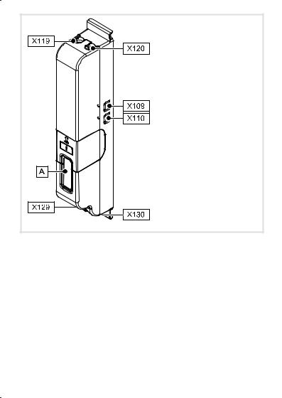
Elemente der DC Einspeisestelle
Pos. Beschreibung
0Typenschild
X109 Durchführung für Stromschiene +UG
X110 Durchführung für Stromschiene −UG
X119 Durchführung für Eingangsleitung +UG
X120 Durchführung für Eingangsleitung −UG
X129 Durchführung für Ausgangsleitung +UG
X130 Durchführung für Ausgangsleitung −UG
4 |
l EDK94AZEX1 DE/EN/FR/ES/IT 3.1 |

Gültigkeit
Diese Anleitung ist gültig für
ƒ DC Einspeisestelle E94AZEX100
Identifikation
L |
|
|
|
|
ERBMXXX011 |
Typenschlüssel |
|
|
|
• |
|
|
|
|
E94 |
A |
Z |
|
E |
X |
100 |
|
|
||||||
|
|
||||||
|
|
|
|
|
|
|
|
Produktreihe
Gerätegeneration
Zubehör
Typ
E = Einspeisestelle
Bemessungsstrom
100 = 100 A
Einsetzbarkeit
Die Verwendung dieser DC Einspeisestelle ist zulässig mit Grundgeräten der Produktreihe 9400 ab der Typenschildbezeichnung
Type |
HW |
SW |
|
E94AxxExxxx |
1A |
˘ |
|
EDK94AZEX1 DE/EN/FR/ES/IT 3.1 |
l |
5 |

i |
Inhalt |
|
1 |
Sicherheitshinweise . . . . . . . . . . . . . . . . . . . . . . . . . . . . . . . . . . . . . . . . . . . . . . . . |
7 |
|
Definition der verwendeten Hinweise . . . . . . . . . . . . . . . . . . . . . . . . . . . . . . . . . |
7 |
|
Restgefahren . . . . . . . . . . . . . . . . . . . . . . . . . . . . . . . . . . . . . . . . . . . . . . . . . . . . . . |
9 |
|
Sicherheitshinweise für die Installation nach UL oder UR . . . . . . . . . . . . . . . . . . |
9 |
2 |
Technische Daten . . . . . . . . . . . . . . . . . . . . . . . . . . . . . . . . . . . . . . . . . . . . . . . . . . |
10 |
|
Allgemeine Daten und Einsatzbedingungen . . . . . . . . . . . . . . . . . . . . . . . . . . . . |
10 |
|
Elektrische Daten . . . . . . . . . . . . . . . . . . . . . . . . . . . . . . . . . . . . . . . . . . . . . . . . . . |
11 |
|
Mechanische Daten . . . . . . . . . . . . . . . . . . . . . . . . . . . . . . . . . . . . . . . . . . . . . . . . |
12 |
3 |
Mechanische Installation . . . . . . . . . . . . . . . . . . . . . . . . . . . . . . . . . . . . . . . . . . . . |
13 |
|
Anordnung der Geräte . . . . . . . . . . . . . . . . . . . . . . . . . . . . . . . . . . . . . . . . . . . . . . |
13 |
|
Montageschritte . . . . . . . . . . . . . . . . . . . . . . . . . . . . . . . . . . . . . . . . . . . . . . . . . . . |
15 |
4 |
Elektrische Installation . . . . . . . . . . . . . . . . . . . . . . . . . . . . . . . . . . . . . . . . . . . . . . |
16 |
|
Anschlussplan . . . . . . . . . . . . . . . . . . . . . . . . . . . . . . . . . . . . . . . . . . . . . . . . . . . . . |
16 |
|
Anschlussdaten . . . . . . . . . . . . . . . . . . . . . . . . . . . . . . . . . . . . . . . . . . . . . . . . . . . . |
17 |
|
Montageschritte . . . . . . . . . . . . . . . . . . . . . . . . . . . . . . . . . . . . . . . . . . . . . . . . . . . |
18 |
6 |
l EDK94AZEX1 DE/EN/FR/ES/IT 3.1 |

Sicherheitshinweise 1
Definition der verwendeten Hinweise
Definition der verwendeten Hinweise
Um auf Gefahren und wichtige Informationen hinzuweisen, werden in dieser Dokumentation folgende Piktogramme und Signalwörter verwendet:
Sicherheitshinweise
Aufbau der Sicherheitshinweise:
}Gefahr!
(kennzeichnet die Art und die Schwere der Gefahr)
Hinweistext
(beschreibt die Gefahr und gibt Hinweise, wie sie vermieden werden kann)
Piktogramm und Signalwort |
Bedeutung |
|
|
Gefahr von Personenschäden durch gefährliche elektrische Span- |
|
{Gefahr! |
nung |
|
Hinweis auf eine unmittelbar drohende Gefahr, die den Tod oder |
|
|
schwere Verletzungen zur Folge haben kann, wenn nicht die |
|
|
|
entsprechenden Maßnahmen getroffen werden. |
|
|
|
|
|
Gefahr von Personenschäden durch eine allgemeine Gefahren- |
|
}Gefahr! |
quelle |
|
Hinweis auf eine unmittelbar drohende Gefahr, die den Tod oder |
|
|
schwere Verletzungen zur Folge haben kann, wenn nicht die |
|
|
|
entsprechenden Maßnahmen getroffen werden. |
|
|
|
|
( Stop! |
Gefahr von Sachschäden |
|
Hinweis auf eine mögliche Gefahr, die Sachschäden zur Folge |
|
|
haben kann, wenn nicht die entsprechenden Maßnahmen ge- |
|
|
|
troffen werden. |
|
Anwendungshinweise |
|
|
|
|
|
Piktogramm und Signalwort |
Bedeutung |
|
) Hinweis! |
Wichtiger Hinweis für die störungsfreie Funktion |
|
|
|
|
|
|
|
I Tipp! |
Nützlicher Tipp für die einfache Handhabung |
|
|
|
|
|
|
|
, |
Verweis auf andere Dokumentation |
|
|
|
|
|
|
|
EDK94AZEX1 DE/EN/FR/ES/IT 3.1 |
l |
7 |

1 Sicherheitshinweise
Definition der verwendeten Hinweise
 Spezielle Sicherheitshinweise und Anwendungshinweise für UL und UR
Piktogramm und Signalwort |
Bedeutung |
|
|
Sicherheitshinweis oder Anwendungshinweis für den Betrieb |
|
J Warnings! |
eines UL−approbierten Geräts in UL−approbierten Anlagen. |
|
Möglicherweise wird das Antriebssystem nicht UL−gerecht betrie- |
|
|
ben, wenn nicht die entsprechenden Maßnahmen getroffen |
|
|
|
werden. |
|
|
|
|
|
Sicherheitshinweis oder Anwendungshinweis für den Betrieb |
|
O Warnings! |
eines UR−approbierten Geräts in UL−approbierten Anlagen. |
|
Möglicherweise wird das Antriebssystem nicht UL−gerecht betrie- |
|
|
ben, wenn nicht die entsprechenden Maßnahmen getroffen |
|
|
|
werden. |
|
8 |
l EDK94AZEX1 DE/EN/FR/ES/IT 3.1 |

Sicherheitshinweise 1
Restgefahren
Restgefahren
{Gefahr!
Gefährliche elektrische Spannung
Während des Betriebs und bis zu 3 Minuten nach dem Netzabschalten können an den Anschlüssen der DC Einspeisestelle gefährliche elektrische Spannungen anliegen.
Mögliche Folgen:
ƒ Tod oder schwere Verletzungen beim Berühren der Anschlüsse.
Schutzmaßnahmen:
ƒVor allen Arbeiten an der Einspeisestelle alle Geräte im Zwischenkreisverbund vom Netz trennen.
ƒAlle Leistungsklemmen auf Spannungsfreiheit prüfen.
Sicherheitshinweise für die Installation nach UL oder UR
JWarnings!
ƒMaximum surrounding air temperature: 55 °C
ƒUse 60/70 °C copper wires only.
ƒUse appropriate listed (ZMVV) wire connectors and soldering lugs, suitable for current and voltage.
EDK94AZEX1 DE/EN/FR/ES/IT 3.1 |
l |
9 |

2 Technische Daten
Allgemeine Daten und Einsatzbedingungen
 Allgemeine Daten und Einsatzbedingungen
Normen |
|
|
|
|
Konformität |
CE |
Niederspannungsrichlinie (73/23/EWG) |
|
|
|
|
|
|
|
Approbation |
UL 508C |
Power Conversion Equipment (File−No. 132659) |
|
|
|
|
|
|
|
Schutz |
|
|
|
|
Schutzart |
EN 60529 |
IP 20 |
|
|
|
|
|
|
|
|
|
NEMA 250 |
Berührschutz nach Typ 1 |
|
|
|
|
|
|
Isolationsfestigkeit |
EN 61800−5−1 |
Überspannungskategorie III |
|
|
|
|
|
Reduzierung ab 2000 m: Überspannungskategorie II |
|
|
|
|
|
|
Umweltbedingungen |
|
|
|
|
Klima |
|
|
|
|
|
|
|
|
|
|
Lagerung |
IEC/EN 60721−3−1 |
1K3 (−25 ... +60 °C) |
|
|
|
|
|
|
|
Transport |
IEC/EN 60721−3−2 |
2K3 (−25 ... +70 °C) |
|
|
|
|
|
|
|
Betrieb |
IEC/EN 60721−3−3 |
3K3 (−10 ... +55 °C) |
|
|
|
|
Leistungsreduzierung von +45 ... +55 °C: 2,5 %/°C |
|
|
|
|
|
|
Aufstellhöhe |
|
0 ... 4000 m üNN |
|
|
|
|
|
Leistungsreduzierung von 1000 ... 4000 m üNN: |
|
|
|
|
5 %/1000 m |
|
Verschmutzung |
EN 61800−5−1 |
Verschmutzungsgrad 2 |
|
|
|
|
|
|
|
Rüttelfestigkeit |
Germanischer |
allgem. Bedingungen: beschleunigungsfest bis 0,7 g |
|
|
|
|
Lloyd |
|
|
10 |
l EDK94AZEX1 DE/EN/FR/ES/IT 3.1 |
|
|
|
|
|
|
Technische Daten 2 |
||||||
|
|
|
|
|
|
|
Elektrische Daten |
|||||
|
Elektrische Daten |
|
|
|
|
|
|
|
|
|
|
|
|
|
|
|
|
|
|
|
|
|
|
|
|
|
|
|
|
|
|
|
|
|
|
|
|
|
|
Grundlage der Daten |
|
|
|
|
|
|
|
|
|
|
|
|
Netz |
Nennspannung UDC Spannungsbereich UDC |
Frequenzbereich |
|
|
|||||||
|
|
|
||||||||||
|
|
[V] |
|
|
|
[V] |
[Hz] |
|
|
|
|
|
|
2/PE DC |
325 |
|
|
260 − 0 % ... 370 + 0 % |
− |
|
|
|
|
||
|
|
|
|
|
|
|
|
|
|
|
|
|
|
2/PE DC |
565 |
|
|
455 − 0 % ... 620 + 0 % |
− |
|
|
|
|
||
|
|
|
|
|
|
|
|
|
|
|
|
|
|
2/PE DC |
705 |
|
|
565 − 0 % ... 775 + 0 % |
− |
|
|
|
|
||
|
|
|
|
|
|
|
|
|
|
|||
|
|
Spannung |
Freq. |
|
Strom [A] |
Strom [A] |
Phasen- |
|
||||
|
Typ |
[V] |
[Hz] |
|
• max. +45° C • max. +55° C |
zahl |
|
|||||
|
|
|
|
|
|
|||||||
|
E94AZEX100 |
325/565/705 |
0 (DC) |
|
100/100/100 |
|
75/75/75 |
2 |
|
|
|
|
|
• Umgebungstemperatur im Schaltschrank |
|
|
|
|
|
|
|
|
|
|
|
EDK94AZEX1 DE/EN/FR/ES/IT 3.1 |
l |
11 |
2 Technische Daten
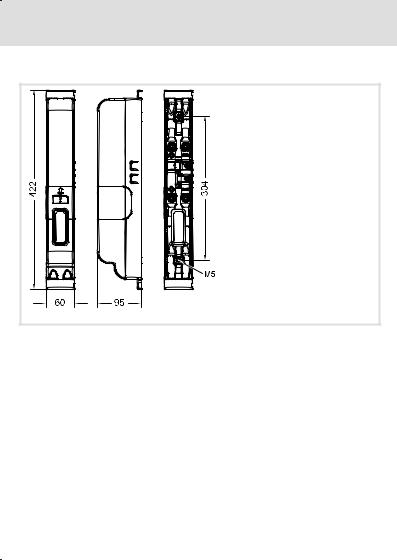
Mechanische Daten
 Mechanische Daten
E94AZEX004
Alle Maße in Millimeter.
Typ |
Masse [kg] |
|
E94AZEX100 |
0,9 |
|
12 |
l EDK94AZEX1 DE/EN/FR/ES/IT 3.1 |
Mechanische Installation 3
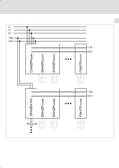
Anordnung der Geräte
Anordnung der Geräte
SSP94PN200
E94AZEX100 |
DC Einspeisestelle |
E94AZPPxxxx |
Montagesockel DC Versorgungsmodul 9400 |
E94AZPxxxxx |
Montagesockel Achsmodul 9400 |
EDK94AZEX1 DE/EN/FR/ES/IT 3.1 |
l |
13 |

3 Mechanische Installation
Anordnung der Geräte
) Hinweis!
Der Montageort und das Montagematerial muss die mechanische Verbindung dauerhaft gewährleisten.
Wir empfehlen zur Befestigung der DC Einspeisestelle, das Lochraster der Achsmodule einzuhalten. Der Lochabstand entspricht dem der Gerätegröße I. Weitere Informationen entnehmen Sie der Montageanleitung zum Achsmodul−Montagesockel (EDK94ZPM113).
14 |
l EDK94AZEX1 DE/EN/FR/ES/IT 3.1 |

Mechanische Installation 3
Montageschritte
Montageschritte
E94AZEX002
EDK94AZEX1 DE/EN/FR/ES/IT 3.1 |
l |
15 |
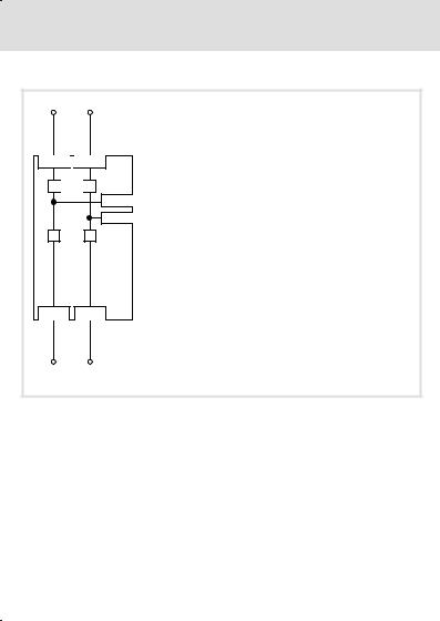
4 Elektrische Installation
Anschlussplan
 Anschlussplan
+UG -UG
X119
 X120
X120
+
 -
-
X109 +UG
X110 -UG
+ |
- |
|
X129 |
X130 |
E94AZEX100 |
+UG |
-UG |
|
E94AZEX006
16 |
l EDK94AZEX1 DE/EN/FR/ES/IT 3.1 |

|
|
|
|
|
|
|
|
|
|
|
|
|
|
|
|
|
|
|
|
Elektrische Installation 4 |
||
|
|
|
|
|
|
|
|
|
|
|
|
|
|
|
|
|
|
|
|
Anschlussdaten |
||
|
Anschlussdaten |
|
|
|
|
|||||||||||||||||
|
|
|
|
|
||||||||||||||||||
|
|
|
|
|
|
|
|
|
|
|
|
|
|
|
|
|
|
|
|
|
||
|
Klemme |
Beschriftung |
Beschreibung |
|
||||||||||||||||||
|
X119/X120/X129/X130 |
|
|
|
|
|||||||||||||||||
|
|
|
|
|
|
|
|
|
|
|
|
|
|
|
|
|
|
|
*/− |
Gewindebolzen zum Anschluss der Eingangs− und Aus- |
||
|
|
|
|
|
|
|
|
|
|
|
|
|
|
|
|
|
|
|
|
gangsleitung (+UG, −UG) mit M8−Ringkabelschuh |
||
|
|
|
|
|
|
|
|
|
|
|
|
|
|
|
|
|
|
|
|
|
|
|
|
|
|
|
|
|
|
|
|
|
|
|
|
|
|
|
|
|
|
|
|
|
|
|
|
|
|
|
|
|
|
|
|
|
|
|
|
|
|
|
|
|
|
|
|
|
|
|
|
|
|
|
|
|
|
|
|
|
|
|
|
|
|
|
|
|
|
|
|
E94AZEX007
Klemmendaten |
max. Leiterquerschnitt |
Anzugsmoment |
Schrauben- |
||
|
[mm2] |
[AWG] |
[Nm] |
[lb−in] |
antrieb |
|
|
||||
E94AZEX100 |
50 |
1 |
7 |
62 |
SW13 |
Klemme X109/X110 |
Beschriftung |
Beschreibung |
|
|
|
|
*/− |
Anschluss der Stromschiene (+UG, −UG) |
|
||
E94AZEX008 |
|
|
|
|
|
Klemmendaten |
max. Leiterquerschnitt |
Anzugsmoment |
Schrauben- |
||
|
[mm2] |
[AWG] |
[Nm] |
[lb−in] |
antrieb |
|
|
||||
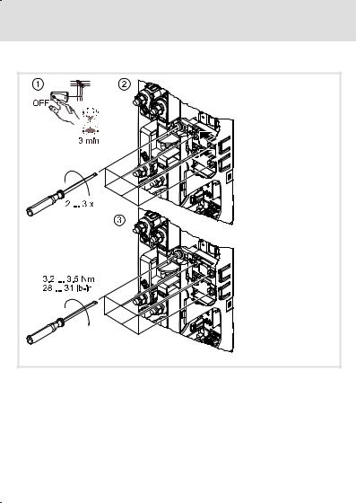
E94AZEX100 |
˘ |
˘ |
3,2 ... 3,5 |
28 ... 31 |
PH2 |
EDK94AZEX1 DE/EN/FR/ES/IT 3.1 |
l |
17 |
4 Elektrische Installation
Montageschritte
 Montageschritte
E94AZEX003
18 |
l EDK94AZEX1 DE/EN/FR/ES/IT 3.1 |

Elektrische Installation 4
Montageschritte
E94AZEX005
EDK94AZEX1 DE/EN/FR/ES/IT 3.1 |
l |
19 |
Scope of supply
Pos. Description
DC input module
Mounting Instructions
DC input module components
Pos. Description
0Nameplate
X109 +UG busbar input
X110 −UG busbar input
X119 +UG cable input
X120 −UG cable input
X129 +UG cable output
X130 −UG cable output
20 |
l EDK94AZEX1 DE/EN/FR/ES/IT 3.1 |
Validity
These instructions are valid for ƒ DC input module E94AZEX100
Identification
L |
|
|
|
|
ERBMXXX011 |
Type code |
|
|
|
• |
|
|
|
|
E94 |
A |
Z |
|
E |
X |
100 |
|
|
||||||
|
|
||||||
|
|
|
|
|
|
|
|
Product range
Device generation
Accessories
Type
E = input module
Rated current 100 = 100 A
Application range
This DC input module can be used with basic devices of the 9400 series as of nameplate designation
Type |
HW |
SW |
|
E94AxxExxxx |
1A |
˘ |
|
EDK94AZEX1 DE/EN/FR/ES/IT 3.1 |
l |
21 |

i |
Contents |
|
1 |
Safety instructions . . . . . . . . . . . . . . . . . . . . . . . . . . . . . . . . . . . . . . . . . . . . . . . . . |
23 |
|
Definition of notes used . . . . . . . . . . . . . . . . . . . . . . . . . . . . . . . . . . . . . . . . . . . . . |
23 |
|
Residual hazards . . . . . . . . . . . . . . . . . . . . . . . . . . . . . . . . . . . . . . . . . . . . . . . . . . . |
25 |
|
Safety instructions for the installation according to UL oder UR . . . . . . . . . . . . . |
25 |
2 |
Technical data . . . . . . . . . . . . . . . . . . . . . . . . . . . . . . . . . . . . . . . . . . . . . . . . . . . . . |
26 |
|
General data and operating conditions . . . . . . . . . . . . . . . . . . . . . . . . . . . . . . . . . |
26 |
|
Electrical data . . . . . . . . . . . . . . . . . . . . . . . . . . . . . . . . . . . . . . . . . . . . . . . . . . . . . |
27 |
|
Mechanical data . . . . . . . . . . . . . . . . . . . . . . . . . . . . . . . . . . . . . . . . . . . . . . . . . . . |
28 |
3 |
Mechanical installation . . . . . . . . . . . . . . . . . . . . . . . . . . . . . . . . . . . . . . . . . . . . . |
29 |
|
Arrangement of the devices . . . . . . . . . . . . . . . . . . . . . . . . . . . . . . . . . . . . . . . . . . |
29 |
|
Mounting steps . . . . . . . . . . . . . . . . . . . . . . . . . . . . . . . . . . . . . . . . . . . . . . . . . . . . |
31 |
4 |
Electrical installation . . . . . . . . . . . . . . . . . . . . . . . . . . . . . . . . . . . . . . . . . . . . . . . |
32 |
|
Connection plan . . . . . . . . . . . . . . . . . . . . . . . . . . . . . . . . . . . . . . . . . . . . . . . . . . . |
32 |
|
Connection data . . . . . . . . . . . . . . . . . . . . . . . . . . . . . . . . . . . . . . . . . . . . . . . . . . . |
33 |
|
Mounting steps . . . . . . . . . . . . . . . . . . . . . . . . . . . . . . . . . . . . . . . . . . . . . . . . . . . . |
34 |
22 |
l EDK94AZEX1 DE/EN/FR/ES/IT 3.1 |

Safety instructions 1
Definition of notes used
Definition of notes used
The following pictographs and signal words are used in this documentation to indicate dangers and important information:
Safety instructions
Structure of safety instructions:
}Danger!
(characterises the type and severity of danger)
Note
(describes the danger and gives information about how to prevent dangerous situations)
Pictograph and signal word |
Meaning |
|
{Danger! |
Danger of personal injury through dangerous electrical voltage. |
|
Reference to an imminent danger that may result in death or |
|
|
serious personal injury if the corresponding measures are not |
|
|
|
taken. |
|
|
|
|
}Danger! |
Danger of personal injury through a general source of danger. |
|
Reference to an imminent danger that may result in death or |
|
|
serious personal injury if the corresponding measures are not |
|
|
|
taken. |
|
|
|
|
( Stop! |
Danger of property damage. |
|
Reference to a possible danger that may result in property |
|
|
damage if the corresponding measures are not taken. |
|
|
|
|
|
Application notes |
|
|
|
|
|
Pictograph and signal word |
Meaning |
|
) Note! |
Important note to ensure troublefree operation |
|
|
|
|
|
|
|
I Tip! |
Useful tip for simple handling |
|
|
|
|
|
|
|
, |
Reference to another documentation |
|
|
|
|
|
|
|
EDK94AZEX1 DE/EN/FR/ES/IT 3.1 |
l |
23 |

1 Safety instructions
Definition of notes used
Special safety instructions and application notes for UL and UR
|
|
Pictograph and signal word |
Meaning |
|
|
||
|
|
|
|
Safety or application note for the operation of a UL−approved
J device in UL−approved systems.
Warnings! Possibly the drive system is not operated in compliance with UL if the corresponding measures are not taken.
Safety or application note for the operation of a UR−approved
O device in UL−approved systems.
Warnings! Possibly the drive system is not operated in compliance with UL if the corresponding measures are not taken.
24 |
l EDK94AZEX1 DE/EN/FR/ES/IT 3.1 |

Safety instructions 1
Residual hazards
Residual hazards
{Danger!
Hazardous electrical voltage
During operation and up to 3 minutes after power−off, hazardous electrical voltages may occur at the DC input module connections.
Possible consequences:
ƒ Death or serious injuries when touching the connections.
Protective measures:
ƒDisconnect all devices in the DC−bus connection from the mains before working on the input module.
ƒCheck if no voltage is applied to the power terminals.
Safety instructions for the installation according to UL oder UR
JWarnings!
ƒMaximum surrounding air temperature: 55 °C
ƒUse 60/70 °C copper wires only.
ƒUse appropriate listed (ZMVV) wire connectors and soldering lugs, suitable for current and voltage.
EDK94AZEX1 DE/EN/FR/ES/IT 3.1 |
l |
25 |

2 |
Technical data |
|
|
|
|||
|
|
|
General data and operating conditions |
||||
|
|
General data and operating conditions |
|||||
|
|
|
|
|
|
|
|
|
|
Standards |
|
|
|
|
|
|
|
Conformity |
CE |
Low−Voltage Directive (73/23/EEC) |
|||
|
|
|
|
|
|
|
|
|
|
Approval |
UL 508C |
Power Conversion Equipment (file no. 132659) |
|||
|
|
|
|
|
|
|
|
|
|
Protection |
|
|
|
|
|
|
|
Enclosure |
EN 60529 |
IP 20 |
|||
|
|
|
|
|
|
|
|
|
|
|
|
NEMA 250 |
Protection against accidental contact acc. to type 1 |
||
|
|
|
|
|
|
|
|
|
|
Insulation resistance |
EN 61800−5−1 |
Overvoltage category III |
|||
|
|
|
|
|
Reduction from 2000 m: Overvoltage category II |
||
|
|
|
|
|
|
|
|
|
|
Environmental conditions |
|
|
|
||
|
|
Climate |
|
|
|
|
|
|
|
|
|
|
|
|
|
|
|
|
Storage |
IEC/EN 60721−3−1 |
1K3 (−25 ... +60 °C) |
||
|
|
|
|
|
|
|
|
|
|
|
Transport |
IEC/EN 60721−3−2 |
2K3 (−25 ... +70 °C) |
||
|
|
|
|
|
|
|
|
|
|
|
Operation |
IEC/EN 60721−3−3 |
3K3 (−10 ... +55 °C) |
||
|
|
|
|
|
Power derating at +45 ... +55 °C: 2.5 %/°C |
||
|
|
|
|
|
|
||
|
|
Site altitude |
|
0 ... 4000 m amsl |
|||
|
|
|
|
|
Power derating at 1000 ... 4000 m amsl: 5 %/1000 m |
||
|
|
|
|
|
|
||
|
|
Pollution |
EN 61800−5−1 |
Pollution degree 2 |
|||
|
|
|
|
|
|
||
|
|
Vibration resistance |
Germanischer |
General conditions: acceleration resistant up to 0.7 g |
|||
|
|
|
|
Lloyd |
|
|
|
26 |
l EDK94AZEX1 DE/EN/FR/ES/IT 3.1 |
Loading...