


 Loading...
 Show/Hide Bookmarks
EDB2102EN
!POn
Ä!POnä
Operating Instructions
LECOM A/ B |
Fieldbus module type 2102
RS232, RS485, optical fibre

 Show/Hide Bookmarks
qЬЙлЙ lйЙк~нбеЦ fелнкмЕнбзел ~кЙ о~дбЗ Сзк СбЙдЗДмл гзЗмдЙл пбнЬ нЬЙ СзддзпбеЦ е~гЙйд~нЙлW
2102 |
IB. |
2x. |
3x. |
V001 |
(RS232, RS485) |
2102 |
IB. |
2x. |
3x. |
V002 |
(RS485) |
2102 |
IB. |
2x. |
3x. |
V003 |
(Optical fibre) |
fе ЕзееЙЕнбзе пбнЬ нЬЙ мебн лЙкбЙл ~л Скзг нЬЙ е~гЙйд~нЙ З~н~W
820X |
E. |
2x. |
1x. |
|
(8201 - 8204) |
820X |
E./C. |
2x. |
1x. |
Vxxx |
(8201 - 8204) |
821X |
E. |
2x. |
2x. |
|
(8211 - 8218) |
821X |
E./C. |
2x. |
2x. |
Vxxx |
(8211 - 8218) |
822X |
E. |
1x. |
1x. |
|
(8221 - 8225) |
822X |
E. |
1x. |
1x. |
Vxxx |
(8221 - 8227) |
824X |
E. |
1x. |
1x. |
|
(8241 - 8246) |
824X |
E./C. |
1x. |
1x. |
Vxxx |
(8241 - 8246) |
82EV |
|
VA |
0x |
|
8200 vector |
82EV |
|
1x |
0x |
|
8200 vector |
93XX |
E. |
2x. |
1x. |
|
(9321 - 9333) |
93XX |
E./C. |
2x. |
1x. |
Vxxx |
(9321 - 9333) |
Type
Design:
E = Built-in unit IP20
IB = Module
Hardware level and index
Software level and index
Version
Explanation
Important:
These Operating Instructions are only valid together with the corresponding Instructions for 82XX, 8200 vector or 93XX controllers.
|
|
|
|
Edition of: |
01.10.2003 |
|
|
|
|
|
|
E 2002 Lenze Drive Systems GmbH
Without written approval of Lenze Drive Systems GmbH this documentation or part of it may not be copied or passed on to third parties.
All information given in this documentation have been checked for compliance with the hardware and software described. Nevertheless, deviations and mistakes cannot be ruled out. We do not take any responsibility or liability for damages which might possibly occur. Necessary corrections will be included in the next edition.
Version |
2.0 |
10/03 |
 Show/Hide Bookmarks
Contents
1 Preface and general information . . . . . . . . . . . . . . . . . . . . . . . . . . . . . . . . . . . . . . . . . . . |
1-1 |
||
1.1 |
About these Operating Instructions . . . . . . . . . . . . . . . . . . . . . . . . . . . . . . . . . . . . . . . . . . . . . . . . . . . . |
1-1 |
|
|
1.1.1 |
Terminology used . . . . . . . . . . . . . . . . . . . . . . . . . . . . . . . . . . . . . . . . . . . . . . . . . . . . . . . . . |
1-1 |
|
1.1.2 |
What is new? . . . . . . . . . . . . . . . . . . . . . . . . . . . . . . . . . . . . . . . . . . . . . . . . . . . . . . . . . . . . |
1-1 |
1.2 |
Packing list . . . . . . . . . . . . . . . . . . . . . . . . . . . . . . . . . . . . . . . . . . . . . . . . . . . . . . . . . . . . . . . . . . . . . |
1-1 |
|
|
1.2.1 |
Legal regulations . . . . . . . . . . . . . . . . . . . . . . . . . . . . . . . . . . . . . . . . . . . . . . . . . . . . . . . . . . |
1-2 |
2 Safety information . . . . . . . . . . . . . . . . . . . . . . . . . . . . . . . . . . . . . . . . . . . . . . . . . . . . . . |
2-1 |
|
2.1 |
Persons responsible for safety . . . . . . . . . . . . . . . . . . . . . . . . . . . . . . . . . . . . . . . . . . . . . . . . . . . . . . . |
2-1 |
2.2 |
General safety information . . . . . . . . . . . . . . . . . . . . . . . . . . . . . . . . . . . . . . . . . . . . . . . . . . . . . . . . . . |
2-1 |
2.3 |
Layout of the safety information . . . . . . . . . . . . . . . . . . . . . . . . . . . . . . . . . . . . . . . . . . . . . . . . . . . . . . |
2-2 |
3 Technical data . . . . . . . . . . . . . . . . . . . . . . . . . . . . . . . . . . . . . . . . . . . . . . . . . . . . . . . . . |
3-1 |
|
3.1 |
Features of the 2102 fieldbus module . . . . . . . . . . . . . . . . . . . . . . . . . . . . . . . . . . . . . . . . . . . . . . . . . . |
3-1 |
3.2 |
General data and application conditions . . . . . . . . . . . . . . . . . . . . . . . . . . . . . . . . . . . . . . . . . . . . . . . . |
3-1 |
3.3 |
Rated data . . . . . . . . . . . . . . . . . . . . . . . . . . . . . . . . . . . . . . . . . . . . . . . . . . . . . . . . . . . . . . . . . . . . . . |
3-2 |
3.4 |
Dimensions . . . . . . . . . . . . . . . . . . . . . . . . . . . . . . . . . . . . . . . . . . . . . . . . . . . . . . . . . . . . . . . . . . . . . |
3-2 |
3.5 |
Communication times . . . . . . . . . . . . . . . . . . . . . . . . . . . . . . . . . . . . . . . . . . . . . . . . . . . . . . . . . . . . . |
3-3 |
4 Installation |
. . . . . . . . . . . . . . . . . . . . . . . . . . . . . . . . . . . . . . . . . . . . . . . . . . . . . . . . . . . . |
4-1 |
|
4.1 |
Connections of the 2102 fieldbus module . . . . . . . . . . . . . . . . . . . . . . . . . . . . . . . . . . . . . . . . . . . . . . . |
4-1 |
|
|
4.1.1 |
Overview . . . . . . . . . . . . . . . . . . . . . . . . . . . . . . . . . . . . . . . . . . . . . . . . . . . . . . . . . . . . . . . . |
4-1 |
|
4.1.2 |
Female plug for 9-pole SubD plug (LECOM-A/B) . . . . . . . . . . . . . . . . . . . . . . . . . . . . . . . . . . . |
4-2 |
|
4.1.3 |
Plug-in terminal for 4-pole male plug (LECOM-B) . . . . . . . . . . . . . . . . . . . . . . . . . . . . . . . . . . |
4-2 |
|
4.1.4 |
Plug-in terminal for 2-pole male plug (external voltage supply) . . . . . . . . . . . . . . . . . . . . . . . . |
4-2 |
4.2 |
Mechanical installation . . . . . . . . . . . . . . . . . . . . . . . . . . . . . . . . . . . . . . . . . . . . . . . . . . . . . . . . . . . . . |
4-3 |
|
4.3 |
Electrical installation . . . . . . . . . . . . . . . . . . . . . . . . . . . . . . . . . . . . . . . . . . . . . . . . . . . . . . . . . . . . . . |
4-3 |
|
4.4 |
Wiring to a host . . . . . . . . . . . . . . . . . . . . . . . . . . . . . . . . . . . . . . . . . . . . . . . . . . . . . . . . . . . . . . . . . . |
4-4 |
|
|
4.4.1 |
Wiring via RS232 (LECOM-A) . . . . . . . . . . . . . . . . . . . . . . . . . . . . . . . . . . . . . . . . . . . . . . . . . |
4-5 |
|
4.4.2 |
Wiring via RS485 (LECOM-B) . . . . . . . . . . . . . . . . . . . . . . . . . . . . . . . . . . . . . . . . . . . . . . . . . |
4-6 |
|
4.4.3 |
Wiring via optical fibres (LECOM-LI) . . . . . . . . . . . . . . . . . . . . . . . . . . . . . . . . . . . . . . . . . . . . |
4-8 |
L |
BA2102EN |
i |
 Show/Hide Bookmarks
Contents
5 |
Commissioning . . . . . . . . . . . . . . . . . . . . . . . . . . . . . . . . . . . . . . . . . . . . . . . . . . . . . . . . |
5-1 |
||
6 |
Parameter setting . . . . . . . . . . . . . . . . . . . . . . . . . . . . . . . . . . . . . . . . . . . . . . . . . . . . . . |
6-1 |
||
|
6.1 |
Parameter sets . . . . . . . . . . . . . . . . . . . . . . . . . . . . . . . . . . . . . . . . . . . . . . . . . . . . . . . . . . . . . . . . . . |
6-1 |
|
|
|
6.1.1 |
82XX parameter sets . . . . . . . . . . . . . . . . . . . . . . . . . . . . . . . . . . . . . . . . . . . . . . . . . . . . . . . |
6-1 |
|
|
6.1.2 |
Parameter sets for 8200 vector . . . . . . . . . . . . . . . . . . . . . . . . . . . . . . . . . . . . . . . . . . . . . . . |
6-1 |
|
|
6.1.3 |
Parameter sets for 93XX . . . . . . . . . . . . . . . . . . . . . . . . . . . . . . . . . . . . . . . . . . . . . . . . . . . . |
6-1 |
|
6.2 |
Meaning of individual parameters . . . . . . . . . . . . . . . . . . . . . . . . . . . . . . . . . . . . . . . . . . . . . . . . . . . . . |
6-2 |
|
|
|
6.2.1 |
Operating mode . . . . . . . . . . . . . . . . . . . . . . . . . . . . . . . . . . . . . . . . . . . . . . . . . . . . . . . . . . . |
6-2 |
|
|
6.2.2 |
LECOM unit address (C0009) . . . . . . . . . . . . . . . . . . . . . . . . . . . . . . . . . . . . . . . . . . . . . . . . . |
6-3 |
|
6.3 |
Special features when using the 82XX controller . . . . . . . . . . . . . . . . . . . . . . . . . . . . . . . . . . . . . . . . . . |
6-4 |
|
|
|
6.3.1 |
Start with Ctrl. inhibit instead of QSP . . . . . . . . . . . . . . . . . . . . . . . . . . . . . . . . . . . . . . . . . . . |
6-4 |
|
|
6.3.2 |
Reduction of the response time of the interface . . . . . . . . . . . . . . . . . . . . . . . . . . . . . . . . . . . |
6-4 |
|
|
6.3.3 |
Communication monitoring . . . . . . . . . . . . . . . . . . . . . . . . . . . . . . . . . . . . . . . . . . . . . . . . . . |
6-4 |
|
6.4 |
Special features when using the 820X controllers . . . . . . . . . . . . . . . . . . . . . . . . . . . . . . . . . . . . . . . . . |
6-5 |
|
|
|
6.4.1 |
Relative setpoint selection C0141 (parameter channel) . . . . . . . . . . . . . . . . . . . . . . . . . . . . . . |
6-5 |
|
|
6.4.2 |
Special features when using the 820X V1.2 controller . . . . . . . . . . . . . . . . . . . . . . . . . . . . . . . |
6-5 |
|
6.5 |
Special notes for 821X, 822X, 824X controllers . . . . . . . . . . . . . . . . . . . . . . . . . . . . . . . . . . . . . . . . . . . |
6-6 |
|
|
6.6 |
Special notes when using 8200 vector controllers . . . . . . . . . . . . . . . . . . . . . . . . . . . . . . . . . . . . . . . . . |
6-6 |
|
7 Troubleshooting and fault elimination . . . . . . . . . . . . . . . . . . . . . . . . . . . . . . . . . . . . . . . |
7-1 |
|||
8 |
Appendix . |
. . . . . . . . . . . . . . . . . . . . . . . . . . . . . . . . . . . . . . . . . . . . . . . . . . . . . . . . . . . . |
8-1 |
|
|
8.1 |
Accessories . . . . . . . . . . . . . . . . . . . . . . . . . . . . . . . . . . . . . . . . . . . . . . . . . . . . . . . . . . . . . . . . . . . . . |
8-1 |
|
|
|
8.1.1 |
Accessories for a host . . . . . . . . . . . . . . . . . . . . . . . . . . . . . . . . . . . . . . . . . . . . . . . . . . . . . . |
8-1 |
|
|
8.1.2 |
Accessories for RS232 (LECOM-A) . . . . . . . . . . . . . . . . . . . . . . . . . . . . . . . . . . . . . . . . . . . . . |
8-1 |
|
|
8.1.3 |
Accessories for RS485 (LECOM-B) . . . . . . . . . . . . . . . . . . . . . . . . . . . . . . . . . . . . . . . . . . . . . |
8-2 |
|
|
8.1.4 |
Accessories for optical fibres (LECOM-LI) . . . . . . . . . . . . . . . . . . . . . . . . . . . . . . . . . . . . . . . . |
8-2 |
|
8.2 |
Code table . . . . . . . . . . . . . . . . . . . . . . . . . . . . . . . . . . . . . . . . . . . . . . . . . . . . . . . . . . . . . . . . . . . . . . |
8-3 |
|
|
8.3 |
LECOM-A/B protocol . . . . . . . . . . . . . . . . . . . . . . . . . . . . . . . . . . . . . . . . . . . . . . . . . . . . . . . . . . . . . . |
8-16 |
|
|
|
8.3.1 |
General . . . . . . . . . . . . . . . . . . . . . . . . . . . . . . . . . . . . . . . . . . . . . . . . . . . . . . . . . . . . . . . . . |
8-16 |
|
|
8.3.2 |
RECEIVE . . . . . . . . . . . . . . . . . . . . . . . . . . . . . . . . . . . . . . . . . . . . . . . . . . . . . . . . . . . . . . . . |
8-21 |
|
|
8.3.3 |
SEND . . . . . . . . . . . . . . . . . . . . . . . . . . . . . . . . . . . . . . . . . . . . . . . . . . . . . . . . . . . . . . . . . . |
8-23 |
|
|
8.3.4 |
BROADCAST / MULTICAST . . . . . . . . . . . . . . . . . . . . . . . . . . . . . . . . . . . . . . . . . . . . . . . . . . . |
8-24 |
|
|
8.3.5 |
Monitoring of the slave response . . . . . . . . . . . . . . . . . . . . . . . . . . . . . . . . . . . . . . . . . . . . . . |
8-24 |
|
|
8.3.6 |
Transmission faults . . . . . . . . . . . . . . . . . . . . . . . . . . . . . . . . . . . . . . . . . . . . . . . . . . . . . . . . |
8-24 |
|
8.4 |
List of abbreviations . . . . . . . . . . . . . . . . . . . . . . . . . . . . . . . . . . . . . . . . . . . . . . . . . . . . . . . . . . . . . . . |
8-25 |
|
|
8.5 |
Glossary |
. . . . . . . . . . . . . . . . . . . . . . . . . . . . . . . . . . . . . . . . . . . . . . . . . . . . . . . . . . . . . . . . . . . . . . . |
8-26 |
|
8.6 |
Index . . |
. . . . . . . . . . . . . . . . . . . . . . . . . . . . . . . . . . . . . . . . . . . . . . . . . . . . . . . . . . . . . . . . . . . . . . . |
8-27 |
ii |
BA2102EN |
L |

 Show/Hide Bookmarks
Preface and general information
1 Preface and general information
1.1About these Operating Instructions
•These Operating Instructions are intended for safety-relevant operations on and with the 2102 fieldbus module. They contain safety information which must be observed.
•All personnel working on and with the 2102 fieldbus module must have these Operating Instructions available and observe the information and notes relevant for them.
•The Operating Instructions must always be complete and perfectly readable.
These Operating Instructions inform about the most important technical data and the installation of the 2102 fieldbus module. They are only valid in combination with the Operating Instructions of the corresponding controller.
1.1.1Terminology used
Controller |
In the following, the term ”controller” is used for ”93XX servo inverters” or ”82XX frequency inverters”. |
Drive system |
In the following the term ”drive system” is used for drive systems with fieldbus modules and other Lenze |
|
drive components. |
|
|
Fieldbus module |
In the following text the term ”fieldbus module” is used for ”fieldbus module type 2102 RS232, RS485, |
|
optical fibre”. |
|
|
Cxxx/y |
Subcode y of code Cxxx (e.g. C0410/3 = subcode 3 of code C0410) |
L-Cxxx/y |
Lenze code |
Xk/y |
Terminal strip Xk/terminal y (e.g. X3/28 = terminal 28 on terminal strip X3) |
( xx-yyy) |
Cross reference (chapter - page) |
1.1.2What is new?
Ident. no. |
edition of |
Important |
Contents |
|
391 845 |
08/1996 |
1st edition |
|
|
394 448 |
02/1997 |
replaces 391 845 |
• extended by 2102.V904, 2102.V905, 2102.V906 |
|
|
|
|
• |
Chapter 6.3 |
|
|
|
• |
Editorially reviewed |
404 788 |
11/1998 |
replaces 394 448 |
Format change to DIN A4 |
|
417 816 |
10/2000 |
replaces 404 788 |
Adaptation to 8200 vector (all chapters) |
|
474 677 |
10/2003 |
replaces 417 816 |
Change of company name |
|
1.2Packing list
Packing list |
Important |
|
• 1 |
2102 fieldbus module with housing (enclosure IP20) |
After the delivery has received, check immediately whether the items |
• 1 |
M3 fixing screw |
supplied match the accompanying papers. Lenze does not accept any |
• 1 two-pole male connector for voltage supply |
liability for deficiencies claimed subsequently. |
|
• 1 |
Short Instructions |
Claim |
|
|
• visible transport damage immediately to the forwarder |
|
|
• visible deficiencies/incompleteness immediately to your Lenze |
|
|
representative. |
|
|
|
L |
_^ONMObk |
1-1 |

 Show/Hide Bookmarks
Preface and general information
1.2.1Legal regulations
Labelling |
Nameplate |
CE identification |
Manufacturer |
|
Lenze 2102 fieldbus modules are |
In compliance with to the EC Low Voltage |
Lenze Drive Systems GmbH |
|
unambiguously identified by their nameplates. |
Directive |
Postfach 10 13 52 |
|
|
|
D-31763 Hameln |
Application as |
2102 fieldbus module |
|
|
directed |
• Operate the fieldbus module only under the conditions prescribed in these Operating Instructions. |
||
|
• The fieldbus module is an additional module and can be optionally attached to the Lenze controller series 820X, 821X, 822X, 8200 vector |
||
|
and 93XX. The 2102 fieldbus module links these Lenze controllers to superimposed hosts (PLC or PC) using the Lenze LECOM A/B/LI |
||
|
fieldbuses. |
|
|
|
• The fieldbus module must be attached and electrically connected so that it complies with its function and does not cause any hazards when |
||
|
attached and operated as instructed. |
|
|
|
• Observe all notes given in chapter “Safety information“ ( 2-1). |
|
|
|
• Please observe all information given in these Operating Instructions. This means: |
|
|
|
– Read these Operating Instructions carefully before you start to work with the system. |
|
|
|
– These Operating Instructions must always be available during operation of the fieldbus module. |
||
|
Any other use shall be deemed inappropriate! |
|
|
Liability |
• The information, data, and notes in these instructions met the state of the art at the time of printing. Claims referring to drive systems |
||
|
which have already been supplied cannot be derived from the information, illustrations, and descriptions given in these Operating |
||
|
Instructions. |
|
|
|
• The specifications, processes, and circuitry described in these Operating Instructions are for guidance only and must be adapted to your |
||
|
own specific application. Lenze does not take responsibility for the suitability of the process and circuit proposals. |
||
|
• The indications given in these Operating Instructions describe the features of the product without warranting them. |
||
|
• Lenze does not accept any liability for damage and operating interference caused by: |
|
|
|
– disregarding these Instructions |
|
|
|
– unauthorized modifications to the controller |
|
|
|
– operating faults |
|
|
|
– improper working on and with the controller |
|
|
|
|
|
|
Warranty |
• Warranty conditions: see Sales and Delivery Conditions of Lenze Drive Systems GmbH. |
|
|
|
• Warranty claims must be made immediately after detecting defects or faults. |
|
|
|
• The warranty is void in all cases where liability claims cannot be made. |
|
|
Disposal |
Material |
recycle |
dispose |
|
Metal |
D |
- |
|
Plastic |
D |
- |
|
Printed-board assemblies |
- |
D |
|
Operating Instructions |
D |
|
1-2 |
_^ONMObk |
L |

 Show/Hide Bookmarks
Safety information
2 Safety information
2.1Persons responsible for safety
Operator
•An operator is any natural or legal person who uses the drive system or on behalf of whom the drive system is used.
•The operator or his safety personnel is obliged
–to ensure the compliance with all relevant regulations, instructions and legislation.
–to ensure that only skilled personnel works on and with the2102IB fieldbus module.
–to ensure that the personnel has the Operating Instructions available for all corresponding work.
–to ensure that all unqualified personnel are prohibited from working on and with the drive system.
Qualified personnel
Qualified personnel are persons who - because of their education, experience, instructions, and knowledge about corresponding standards and regulations, rules for the prevention of accidents, and operating conditions - are authorized by the person responsible for the safety of the plant to perform the required actions and who are able to recognize potential hazards.
(Definition for qualified personnel to VDE 105 or IEC 364)
2.2General safety information
•These safety notes do not claim to be complete. In case of questions and problems please contact your Lenze representative.
•At the time of delivery the fieldbus module meets the state of the art and ensures basically safe operation.
•The indications given in these Operating Instructions refer to the stated hardware and software versions of the fieldbus modules.
•The fieldbus module is hazardous if:
–unqualified personnel works on and with the fieldbus module.
–the fieldbus module is used inappropriately.
•The processing notes and circuit sections shown in these Operating Instructions are proposals which cannot be transferred to other applications without being tested and checked.
•Ensure by appropriate measures that neither personal injury nor damage to property may occur in the event of failure of the fieldbus module.
•The drive system must only be operated when no faults occur.
•Retrofittings, modifications, or redesigns are basically prohibited.Lenze must be contacted in all cases.
•The fieldbus module is electrical equipment intended for use in industrial high-power plants. The fieldbus module must be tightly screwed to the corresponding controller during operation. In addition, all measures described in the Operating Instructions of the controller used must be taken. Example: Fasten covers to ensure protection against contact.
L |
_^ONMObk |
2-1 |
 Show/Hide Bookmarks
Safety information
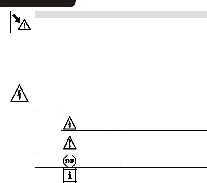
2.3Layout of the safety information
•All safety information have a uniform layout:
–The icon characterizes the type of danger.
–The signal word characterizes the severity of danger.
–The note text describes the danger and gives information on how to prevent dangerous situations.
Signal word
Note
|
Icons used |
Signal words |
|
Warning of |
Warning of |
Danger! |
Warns of impending danger. |
damage to |
hazardous electrical |
|
Consequences if disregarded: |
persons |
voltage |
|
Death or severe injuries. |
|
Warning of a general |
Warning! |
Warns of potential, very hazardous situations. |
|
danger |
|
Possible consequences if disregarded: |
|
|
|
Death or severe injuries. |
|
|
Caution! |
Warns of potential, hazardous situations. |
|
|
|
Possible consequences if disregarded: |
|
|
|
Light or minor injuries. |
Warning of |
|
Stop! |
Warns of potential damage to material. |
damage to |
|
|
Possible consequences if disregarded: |
material |
|
|
Damage of the controller/drive system or its environmentK |
Other notes |
|
Tip! |
This note designates general, useful notes. |
|
|
|
If you observe it, handling of the controller/drive system is made |
|
|
|
easier. |
2-2 |
_^ONMObk |
L |
 Show/Hide Bookmarks
Technical data
3 Technical data
3.1Features of the 2102 fieldbus module
The 2102 fieldbus module has the following features:
•Different communication media:
–RS232 (LECOM-A)
–RS485 (LECOM-B)
–Optical fibre (LECOM-LI)
•LECOM protocol V2.0
•The baud rate can be set to 1200, 2400, 4800, 9600 or 19200 baud (bit/s).
•Parameter setting via controller code numbers
•3 Diagnostic LEDs
•Electrical isolation between control stage and power stage
•Electrical isolation of the I/O terminals of 821X, 8200 vector, 822X and 93XX
•Easy installation
3.2General data and application conditions
Field |
Values |
|
|
|
|
Communication media |
RS232 (LECOM-A): copper conductor |
|
|
||
|
RS485 (LECOM-B): copper conductor |
|
|
||
|
(LECOM-LI): optical fibre |
|
|
|
|
|
|
|
|
|
|
Protocol |
LECOM-A/B V2.0 |
|
|
|
|
Character |
7 bit ASCII |
|
|
|
|
Format |
1 Stop bit |
|
|
|
|
|
1 Start bit |
|
|
|
|
|
1 Parity bit (even) |
|
|
|
|
Baud rate [bits/s] |
1200, 2400, 4800, 9600, 19200 |
|
|
|
|
|
|
|
|
|
|
Ambient temperature |
During operation: |
0 |
to |
+50 C |
|
|
Transport: |
–25 |
to |
+70 C |
|
|
Storage: |
–25 |
to |
+55 C |
|
Permissible moisture |
Class 3K3 to EN 50178 (without condensation, average relative humidity 85%) |
|
|||
|
|
|
|||
24-V-DC- |
• 820X / 8200 vector (observe chapter 4.3): |
only external supply |
|||
Voltage supply |
• 821X / 822X / 8200 vector (observe chapter 4.3) / 93XX: |
internal or external supply |
|||
|
|
|
|
|
|
L |
_^ONMObk |
3-1 |
 Show/Hide Bookmarks
Technical data
3.3Rated data
|
|
2102IB.V001 |
|
2102IB.V002 |
2102IB.V003 |
|
Communication media |
|
RS232 (LECOM-A) |
|
RS485 (LECOM-B) |
Optical fibre |
|
|
|
RS485 (LECOM-B) |
|
|
(LECOM-LI) |
|
|
|
|
|
|
|
|
Current consumption |
|
|
80 mA |
|
60 mA |
70 mA |
External supply |
V = 24 V DC |
|
|
|
|
|
(terminals 39/59) |
VRMS = 15 |
TO 30 |
V DC; W = 5 % |
|
|
|
|
VRMS = 20 |
TO 25 |
V DC; W = 48 %; VSS 35 V |
|
|
|
2102IB.V001 / 2102IB.V002 / 2102IB.V003:
|
|
|
|
Rated insulation voltage |
|
Type of insulation |
|
|
|
|
|
|
|
|
• |
to PE |
|
50 V AC |
|
no electrical isolation |
|
• for external supply (terminals 39/59) |
- |
|
no electrical isolation |
||
|
|
|
|
|
|
|
|
• |
for power stage |
|
|
|
|
|
|
– 820X / 821X |
|
270 V AC |
|
basic insulation |
|
|
|
|
|||
|
|
– 822X / 8200 vector |
|
270 V AC |
|
double basic insulation |
|
|
– 93XX |
|
270 V AC |
|
double basic insulation |
Insulation voltages |
|
|
|
|
|
|
• |
for control terminals |
|
|
|
|
|
for bus systems |
|
– 820X / 8200 vector |
|
- |
|
no electrical isolation |
|
|
|
||||
|
|
|
|
|||
|
|
(with internal supply) |
|
|
|
|
|
|
– 8200 vector |
|
100 V AC |
|
basic insulation |
|
|
(with external supply) |
|
|
|
|
|
|
– 821X |
|
50 V AC |
|
electrical isolation |
|
|
– 822X |
|
270 V AC |
|
basic insulation |
|
|
– 93XX |
|
270 V AC |
|
basic insulation |
|
|
|
|
|
|
|
|
• |
for external bus systems |
|
50 V AC |
|
electrical isolation |
|
|
|
|
|
|
|
Degree of pollution |
VDE 0110 part 2 pollution degree 2 |
|
|
|
|
|
|
|
|
|
|
|
|
3.4Dimensions
|
|
|
|
|
|
|
|
|
|
|
|
|
|
|
|
|
|
|
|
|
|
|
|
|
|
|
|
|
|
|
|
|
|
|
|
|
|
|
|
|
|
|
|
|
|
|
|
|
|
|
|
|
|
|
|
|
|
|
|
|
|
|
|
|
|
|
|
|
|
|
|
|
|
|
|
|
|
|
|
|
|
|
|
|
|
|
|
|
|
|
|
|
|
|
|
|
|
|
|
|
|
|
|
|
|
|
|
|
|
|
|
|
|
|
|
|
|
|
|
|
|
|
|
|
|
|
|
|
|
|
|
|
|
|
|
|
|
|
|
|
|
|
|
|
|
|
|
|
|
|
|
|
|
|
|
|
|
|
|
|
|
|
|
|
|
|
|
|
|
|
|
|
|
|
|
|
|
|
|
|
|
|
|
|
|
|
|
|
|
|
|
|
|
|
|
|
|
|
|
|
|
|
|
|
|
|
|
|
|
|
|
|
|
|
|
|
|
|
|
|
|
|
|
|
|
|
|
|
|
|
|
|
|
|
|
|
|
|
|
|
|
|
|
|
|
|
|
|
|
|
|
|
|
|
|
|
|
|
|
|
|
|
|
|
|
|
|
|
|
|
|
|
|
|
|
|
|
|
|
|
|
|
|
|
|
|
|
|
|
|
|
|
|
|
|
|
|
|
|
|
|
|
|
|
|
|
|
|
|
|
|
|
|
|
|
|
|
|
|
|
|
|
|
|
|
|
|
|
|
|
|
|
|
|
|
|
|
|
|
|
|
|
|
|
|
|
|
|
|
|
|
|
|
|
|
|
|
|
|
|
|
|
|
|
|
|
|
|
|
|
|
|
|
|
|
|
|
|
|
|
|
|
|
|
|
|
|
|
|
|
|
|
|
|
|
|
|
|
|
|
|
|
|
|
|
|
|
|
|
|
|
|
|
|
|
|
|
|
|
|
|
|
|
|
|
|
|
|
|
|
|
|
|
|
|
|
|
|
|
|
|
|
|
|
|
|
|
|
|
|
|
|
|
|
|
|
|
|
|
|
|
|
|
|
|
|
|
|
|
|
|
|
|
|
|
|
|
|
|
|
|
|
|
|
|
|
|
|
|
|
|
|
|
|
|
|
|
|
|
|
|
|
|
|
|
|
|
|
|
|
|
|
|
|
|
|
|
|
|
|
|
|
|
|
|
|
|
|
|
|
|
|
|
|
|
|
|
|
|
|
|
|
|
|
|
|
|
|
|
|
|
|
|
|
|
|
|
|
|
|
|
|
|
|
|
|
|
|
|
|
|
|
|
|
|
|
|
|
|
|
|
|
|
|
|
|
|
|
|
|
|
|
|
|
|
|
|
|
|
|
|
|
|
|
|
|
|
|
|
|
|
|
|
|
|
|
|
|
|
|
|
|
|
|
|
|
|
|
|
|
|
|
|
|
|
|
|
|
|
|
|
|
|
|
|
|
|
|
|
|
|
|
|
|
|
|
|
|
|
|
|
|
|
|
|
|
|
|
|
|
|
|
|
|
|
|
|
|
|
|
|
|
|
|
|
|
|
|
|
|
|
|
|
|
|
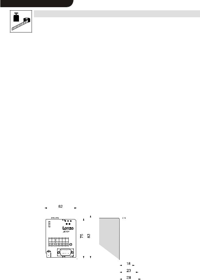
Fig. 3-1 |
Dimensions of the 2102 fieldbus module (all dimensions in mm) |
|
|
|
|
|
|
|
||||||||||||||||||||
3-2 |
_^ONMObk |
L |
 Show/Hide Bookmarks
Technical data
3.5Communication times
The time required for communication can be displayed as a sequence of processing steps (with corresponding times).
Step |
Explanation |
t0 |
User program in host starts request to the controller (e.g. controller enable with C0040=1) |
t1 |
Software driver (e.g. LECOM-S5) in host converts request data into LECOM-A/B protocol V2.0 and starts the transmission. |
|
|
t2 |
Serial data transfer to the controller (telegram time) |
t3 |
Data receipt of the controller: Processing of request and start of response |
|
|
t4 |
Response data to host are being transmitted (telegram time) |
t5 |
Software driver in host evaluates the response, i.e. the response is converted into the format of the user program. |
t6 |
Application program in host gets the result |
The time sections t2, t4 and t3 are described in detail in the following:
Telegram time (t2 + t4)
The telegram time comprises the serial communication from the host to the controller (t2) and the corresponding response from the controller (t4). The time depends on the telegram type and the baud rate set under C0125.
|
|
Baud rate [bits/s] (C0125) |
|
||
|
1200 |
2400 |
4800 |
9600 |
19200 |
Single character transmission time [ms] |
8.4 |
4.2 |
2.1 |
1 |
0.52 |
(1 character = 10 bit; see chapter 3.2) |
|
|
|
|
|
|
|
|
|
|
|
Telegram type SEND (sends data to drive):
|
|
Baud rate [bits/s] (C0125) |
|
||
|
1200 |
2400 |
4800 |
9600 |
19200 |
t2: Standard [ms] (parameter value = 9 characters) |
150 |
75 |
37.5 |
18.8 |
9.4 |
|
|
|
|
|
|
Addition for extended addressing [ms] |
41.6 |
20.8 |
10.4 |
5.2 |
2.6 |
Telegram type RECEIVE (reads data from drive):
|
|
|
Baud rate [bits/s] |
|
|
||
|
1200 |
2400 |
|
4800 |
|
9600 |
19200 |
Standard [= t4] |
166.7 |
83.3 |
|
41.7 |
|
20.8 |
10.4 |
(Parameter value = 9 characters) [ms] |
|
|
|
|
|
|
|
|
|
|
|
|
|
|
|
Addition for extended addressing [ms] |
83.3 |
41.7 |
|
20.8 |
|
10.4 |
5.2 |
If more or fewer than 9 characters are transmitted as telegram data, take the corresponding character-transmission times into account.
L |
_^ONMObk |
3-3 |
 Show/Hide Bookmarks
Technical data
Processing time in the controller (t3)
The processing time in the controller depends on the controller type and the code numbers. This is shown in the following table:
Code numbers |
|
Processing time (2102 + controller) [ms] |
|
||
|
|
|
Series |
|
|
|
820X |
|
821X/8200 vector/822X |
|
93XX |
|
|
|
|||
C0046, C0135 |
35 1) |
|
20 |
|
20 3) |
C0050, C0150 |
35 |
|
20 |
|
20 |
C0068 |
70 |
|
30 |
|
30 |
|
|
|
|
|
|
Write other code numbers |
230 |
|
20 2) |
|
20 4) |
Read other code numbers |
55 |
|
20 |
|
20 |
1)35 ms is valid for C0001 = 3. If C0001 = 1 and you write under C0046, access is also possible. However, the processing time is prolonged to 70 ms.
2)For immediately following write-access procedures, the response times may be up to 50ms.
3)The code number C0046 can only be read. Use a free code number (e. g. C0141) to select a setpoint. For this, refer to the 93XX Manual.
4)This is a typical value. For some codes, the processing times may be longer. For this, refer to the 93XX Manual.
3-4 |
_^ONMObk |
L |
 Show/Hide Bookmarks
Installation
4 Installation
4.1Connections of the 2102 fieldbus module
4.1.1Overview
UOMM оЙЕнзк |
UOuu
VPuu
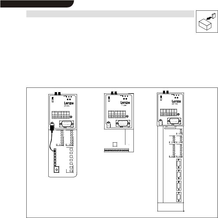
Fig. 4-1 |
82XX, 8200 vector and 93XX controllers (with fieldbus module 2102) |
L |
_^ONMObk |
4-1 |
 Show/Hide Bookmarks
Installation
|
Pos. |
Name/Meaning |
|
Note |
|
|
|
|
|
|
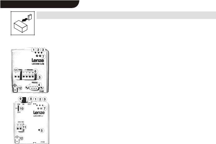
1 |
Green bus LED (voltage supply) |
|
|
|
|
ON: |
Fieldbus module has connected with the controller. |
|
|
|
BLINKING: |
2102 fieldbus module is supplied with voltage but is |
|
|
|
not connected to the controller (controller is switched off, in |
|
|
|
|
initialization or not available). |
|
|
|
|
|
|
|
|
2 |
Yellow RxD-LED For receiving signal: |
|
|
|
|
BLINKING: |
Drive unit receives telegram |
|
|
|
|
|
|
|
3 |
Yellow TxD-LED For sending signal: |
|
|
|
|
BLINKING: |
Drive unit transmits response |
|
|
|
|
|
|
|
4 |
9-pole SubD female plug for the RS232/RS485 interface |
only with 2102IB.V901/2102.V904 |
|
|
|
|
|
|
|
5 |
Fixing screw |
|
|
|
|
|
|
|
|
6 |
4-pole clamp-plug connection for RS485 interface |
only with 2102IB.V901/2102.V904 and |
|
|
|
|
|
2102IB.V902/2102.V905 |
|
|
|
|
|
|
7 |
Operating status display for the controller |
|
|
|
|
|
|
|
|
8 |
Optical-fibre transmitter (white) |
only with 2102IB.V903/2102.V906 |
|
|
|
|
|
|
|
9 |
Optical-fibre receiver (black) |
only with 2102IB.V903/2102.V906 |
|
|
|
|
|
|
|
10 |
Switch S1 for optical-fibre transmission rate: |
only with 2102IB.V903/2102.V906 |
|
|
|
OFF: |
normal transmission rate (0 to 40m) |
|
|
|
ON: |
= high transmission rate (10 to 66m) |
|
|
|
|
|
|
|
11 |
Connection for external voltage supply (24 V DC ± 10 %) |
|
|
|
|
|
|
|
|
12 |
PE connection (only for 82XX) |
|
|
|
|
|
|
|
Fig. 4-2 |
- |
RS 485 cable (no drawing) |
only with 2102IB.V901/2102.V904 and |
|
|
|
|
|
2102IB.V902/2102.V905 |
|
|
|
|
|
4.1.2Female plug for 9-pole SubD plug (LECOM-A/B)
Pin |
Name |
Input/output |
Explanation |
1 |
- |
- |
Not assigned |
2 |
RxD |
Input |
Data receiving wire RS232 |
|
|
|
|
3 |
TxD |
Output |
Data transmitting wire RS232 |
4 |
DTR |
Output |
Transmission control RS232 |
5 |
GND |
- |
Reference potential |
|
|
|
|
6 |
DSR |
Input |
Not assigned RS232 |
7 |
T/R(A) |
Input/output |
RS485 |
8 |
T/R(B) |
Input/output |
RS485 |
|
|
|
|
9 |
Vcc5 |
Output |
Supply +5 V / 10 mA |
4.1.3Plug-in terminal for 4-pole male plug (LECOM-B)
Pin |
Name |
Input/output |
Explanation |
71 |
T/R(B) |
Input/output |
RS485 |
72 |
T/R(A) |
Input/output |
RS485 |
|
|
|
|
88 |
S-C |
- |
Capacitive screening to PE |
89 |
S |
- |
Direct screening to PE |
4.1.4Plug-in terminal for 2-pole male plug (external voltage supply)
Pin |
Name |
Input/output |
Explanation |
39/− |
GND24 |
- |
Reference potential for external supply |
59/+ |
Vcc24 |
Input |
External supply 15 to 30 V DC (see chapter 4.3) |
4-2 |
_^ONMObk |
L |
 Show/Hide Bookmarks
Installation
4.2Mechanical installation
•Remove the keypad from the front of the controller if it is attached.
•Attach the 2101 fieldbus module to the front of the controller. Use the fixing screw, which is part of the delivery package, to secure the fieldbus module (see Fig. 4-1, pos. 3) ( 1-1).
Stop!
Tighten the fixing screw to ensure adequate PE connection of the 2102 fieldbus module.
4.3Electrical installation
•The communication of controllers 820X and 821X may be disturbed by electromagnetic radiation. Use an additional PE cable to ensure safe communication (see Fig. 4-1 pos. 13). This is not necessary with the controllers 822X and 93XX.
Caution!
The bus system continues operation even if the 2102 fieldbus system is disconnected from the power supply because of an error.
If this is the case, the controller cannot be reached by the host.
Stop!
The polarity of the voltage supply must not be reversed, otherwise, the 2102 fieldbus module will be destroyed !
•Voltage supply:
–external 24 V (15 to 30 V) via plug-in connectors 39 (-) / 59 (+) or
–internal via the controller (connection by plugging it on).
With 820X it is not possible to have an internal voltage supply via the controller.
L |
_^ONMObk |
4-3 |
 Show/Hide Bookmarks
Installation
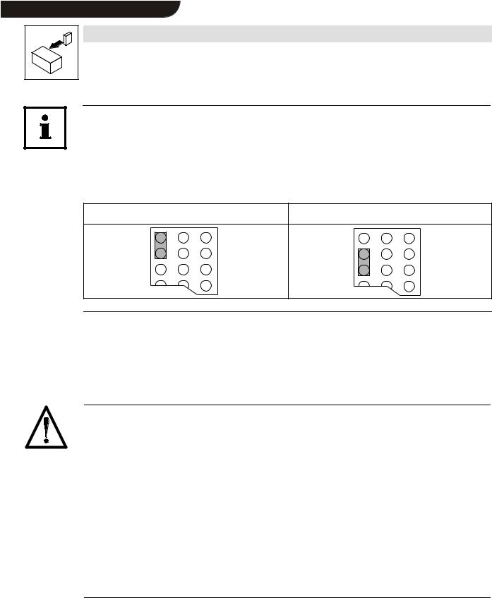
Note!
Internal voltage supply of the fieldbus module connected to a 8200 vector
Controllers with an extended AIF interface (front of the 8200 vector) can be internally supplied. The part of the drawing highlighted with grey shows the jumper position.
In Lenze setting, the fieldbus module is not internally supplied.
For internal voltage supply, put the jumper in the position indicated below.
Lenze setting |
Internal voltage supply |
(only external voltage supply)
4.4Wiring to a host
This chapter informs you about networking the 2102 fieldbus module using the bus systems RS232 (LECOM-A), RS485 (LECOM-B) or optical fibres (LECOM-LI).
The accessories requires are listed in chapter 8.1.
Danger!
•An additional electrical isolation is required if
–a 820X, 821X or 8200 vector controller will be connected to a host
–a safe electrical isolation (double basic insulation) to VDE 0160 is required.
•Please observe the following:
–RS232:
The electrical isolation of the RS232 interface (LECOM-A) can be achieved by two 2101IB level converters or another RS232 electrical isolation.
–RS485:
With RS485 (LECOM-B), the 2101IB level converter should be installed to the host if it is not equipped with an appropriately isolated interface.
–Optical fibres:
If two controllers are connected via optical fibres (LECOM-LI) they are always isolated.
•For wiring, the electrical isolation of the supply voltage must be taken into account.
The controllers 822X and 93XX are equipped with a double basic insulation to VDE 0160, additional electrical isolation is therefore not necessary.
4-4 |
_^ONMObk |
L |
 Show/Hide Bookmarks
Installation
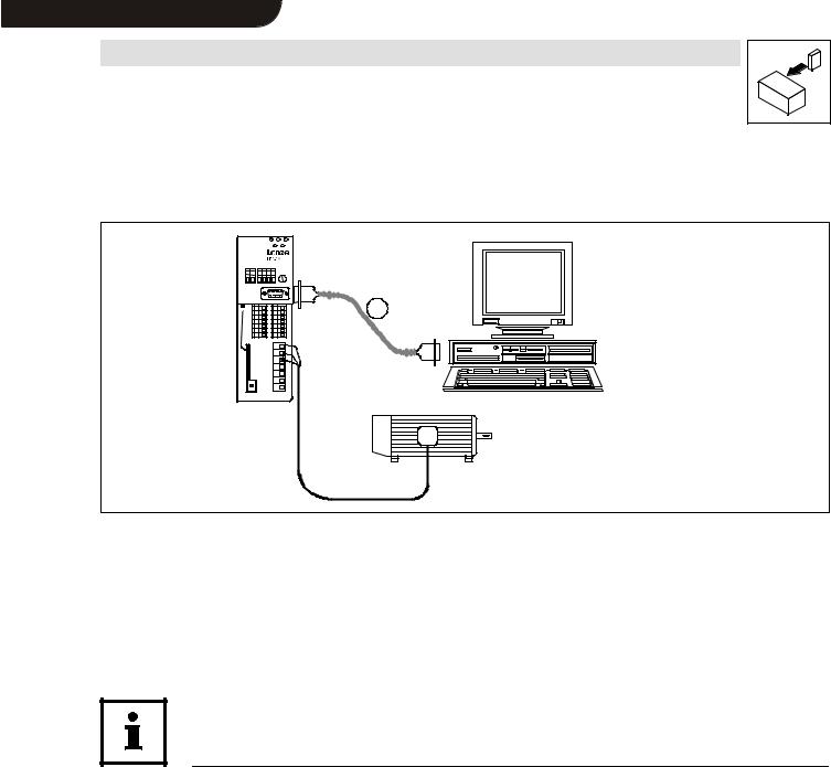
4.4.1Wiring via RS232 (LECOM-A)
The following figure schematically shows the connection to a host (here: PC)via RS232 (LECOM-A).
S1
LEMOC
1
PC system cable
Fig. 4-3 |
Wiring for RS232 (LECOM-A) |
Wiring features for RS232 (LECOM-A):
Type |
2102IB.V001 |
|
Communication media |
RS232 |
|
Network topology |
Point-to-point |
|
Possible number of controllers |
1 |
|
Maximum cable length |
15 m |
|
Maximum baud rate |
19200 bit/s |
|
|
|
|
Note!
We recommend the use of ready-made PC system cables for wiring (see chapter 8.1.2).
Wire the PC system cables as described:
1.Use metallic SubD connector shells and connect both ends of the screen to the connector shells.
2.Connect the pins as follows:
Unit |
Connection element |
|
|
Pin-No. (name) |
|
|||
|
|
|
|
|
|
|
|
|
2102 fieldbus module |
9-pole SubD plug |
2 |
(RxD) |
|
3 |
(TxD) |
|
5 (GND) |
|
|
|
|
|
|
|
|
|
Host (PC, PLC, etc.) |
9-pole SubD female plug |
3 |
(TxD) |
|
2 |
(RxD) |
|
5 (GND) |
|
|
|
|
|
|
|
|
|
25-pole SubD female plug. |
2 |
(TxD) |
|
3 |
(RxD) |
|
7 (GND) |
|
|
|
|
||||||
|
|
|
|
|
|
|
|
|
L |
_^ONMObk |
4-5 |

 Show/Hide Bookmarks
Installation
4.4.2Wiring via RS485 (LECOM-B)
The following figure schematically shows the connection to a host (PC or PLC) via RS485 (LECOM-B).
|
|
|
|
|
RS232 |
|
|
|
|
|
|
|
RS485 |
|
|
|
|
|
|
|
|
3 |
|
S1 |
|
S1 |
|
S1 |
2a |
4 |
|
|
RS485 |
|
RS485 |
|
RS485 |
||
5939 7172889 |
5939 71728889 |
5939 71728889 |
2101IB |
||||
|
|
|
|||||
|
|
|
|
1 |
1 |
2b |
|
|
|
|
|
|
|
|
Fig. 4-4 |
Wiring for RS485 (LECOM-B) |
|
|
|||
|
|
|||||
Interface cable RS485
Optional host connection
a)directly RS485
b)RS232 via interface converter 2101IB
PC system cable
2101IB interface converter
Note!
• We recommend the use of appropriate accessories (see chapter 8.1.3).
•Please do not use any other but a shielded and twisted cable for wiring the RS485 interface cable.
Wiring features for RS485 (LECOM-B):
Type |
2102IB.V002 |
|
|
Communication media |
RS485 (2 wires) |
|
|
Network topology |
Line |
|
|
Possible number of controllers |
31 |
|
|
Maximum cable length |
1200 m |
|
|
Maximum baud rate |
19200 bit/s |
|
|
4-6 |
_^ONMObk |
L |
 Show/Hide Bookmarks
Installation
PC/PLC
T/R/(A)
T/R/(B)
PE
71 72 88 89 |
71 |
72 88 |
2102 |
|
2102 |
Controller |
Controller |
|
1 |
2 |
|
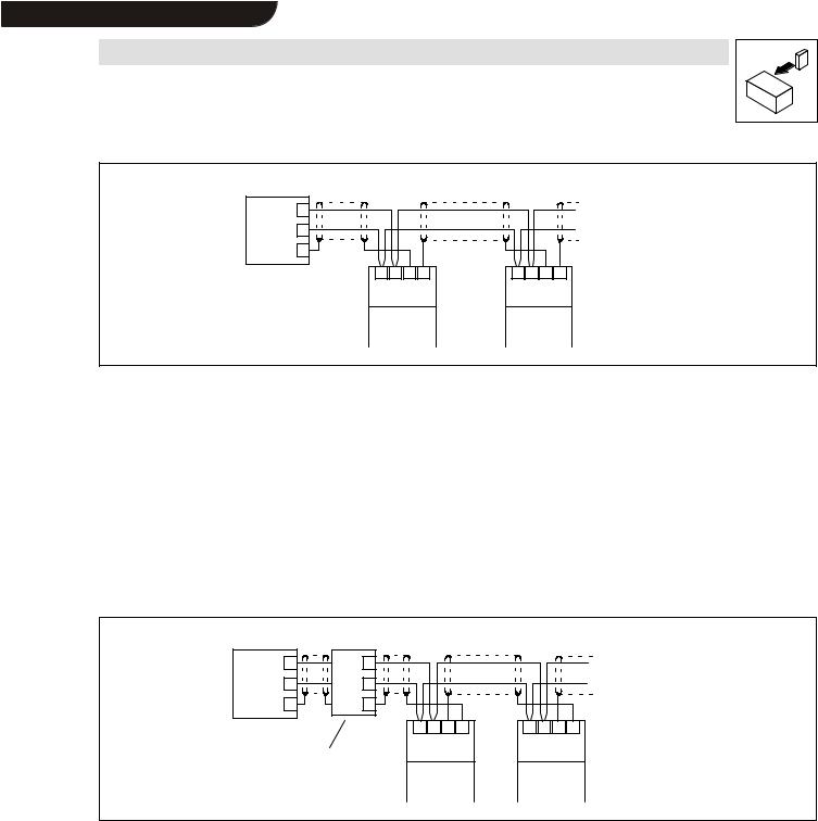
Fig. 4-5 |
Connection to the host (PC/PLC) |
Connection between two controllers (cable 1 in Fig. 4-4):
•Connect the cable shield with terminal 89 (direct PE) of one fieldbus module and terminal 88 (capacitive PE) of the other fieldbus module (Fig. 4-5).
This method prevents currents flowing through the cable screens.
•Connect the terminals 71 and 72 between the fieldbus modules via paired cables (e.B. green and yellow).
Direct connection to the host (cable 2a in Fig. 4-4)
•Connect the host cable screen to PE and the controller cable screen to terminal 88. This method prevents currents flowing through the cable screens.
Connection to the 201IB interface converter (cable 2b in Fig. 4-4):
PC/PLC |
|
|
|
RxD |
72 |
|
|
TxD |
71 |
|
|
PE |
88 |
|
|
|
|
71 72 88 89 |
71 72 88 89 |
2101IB interface converter |
2102 |
2102 |
|
|
|
||
|
|
Controller |
Controller |
|
|
1 |
2 |
Fig. 4-6 Connection to the 2101IB interface converter
•Connect the cable shield with terminal 89 (direct PE) of the last controller and terminal 88 (capacitive PE) of the interface converter (Fig. 4-6).
This method prevents currents flowing through the cable screens.
L |
_^ONMObk |
4-7 |
Loading...