


 Loading...
Inverter
8400 |
E84AVSCxxxxx... |
Inverter Drives 8400 StateLine C _ _ _ _ _ _ _ _ _ _ _ _ _ |
Operating Instructions |
EN |
Ä.H)oä 13390878
L
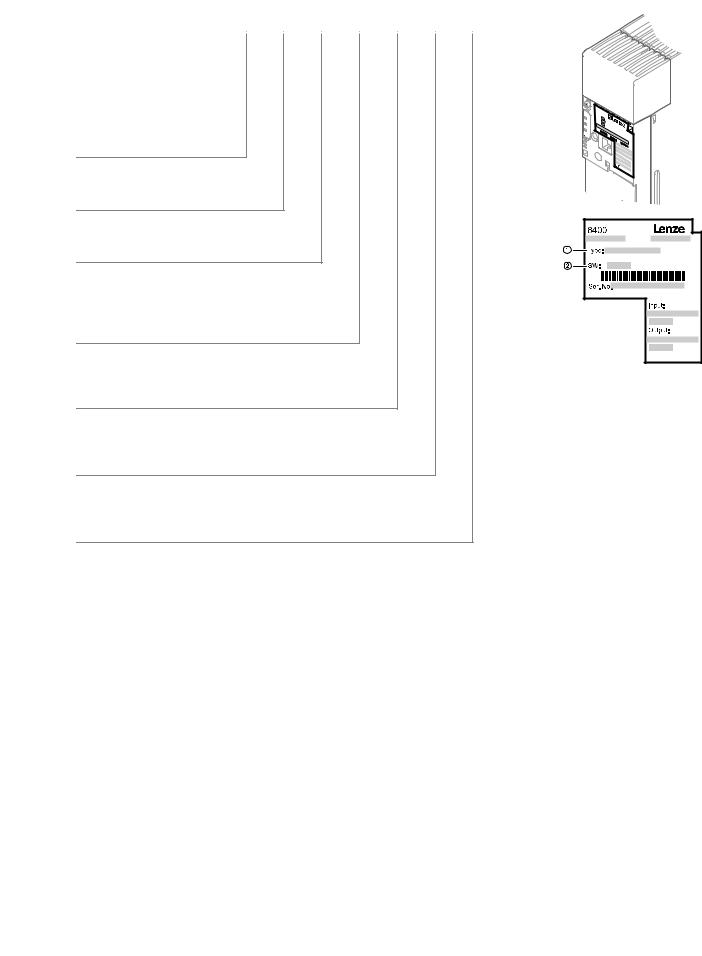
Product key
_ _ _ _ _ _ _ _ _ _ _ _ _ _ _ _ _ _ _ _ _ _ _ _ _ _ _ _ _ _ _ _ _ _ _ _ _ _ _ _ _ _ _ _ _ _ _ _ _ _ _ _ _ _ _ _ _ _ _ _ _ _ _ _
Product key: |
Nameplate: |
|
E84 |
A |
V |
SC |
x |
xxx |
x |
x |
x |
x |
||
Product range |
|
|
|
|
|
|
|
|
|
|
|
|
|
|
|
|
|
|
|
|
|
|
|
|
|
8400 Inverter Drives |
|
|
|
|
|
|
|
|
|
|
||
Generation |
|
|
|
|
|
|
|
|
|
|
||
|
|
|
|
|
|
|
|
|
|
|
||
A = 1. generation |
|
|
|
|
|
|
|
|
|
|
||
Type
V = vector-controlled inverter
Version
SC = StateLine C
Mounting type
E = installation
D = Push-trough technique
C = cold-plate technique
Power e.g.
251 = 25 x 101 W = 0.25 kW 222 = 22 x 102 W = 2.2 kW
Voltage class
2 = 230/240 V, 1/N/PE AC (0.25 ... 2.2 kW) 4 = 400/500 V, 3/PE AC (0.37 ... 45 kW)
Ambient conditions
S = standard industrial environment IE33 according to IEC 60721-3-3
V = rough environment (coated printed circuit boards)
Safety system
X = without safety technology
B = with drive-based safety "safe torque off (STO)"
The product key serves to identify delivered products by nameplate data.
The product catalogue provides information on the possible configuration to order the products.
Type designation Software version
Tip!
Current instructions for the contents of the product CD and information and tools for the Lenze products are provided in the internet:
http://www.Lenze.com Download
2 |
Lenze · 8400 StateLine · Operating instructions · from Firmware V06.00 · DMS 1.2 EN · 12/2012 · TD05 |
Contents
_ _ _ _ _ _ _ _ _ _ _ _ _ _ _ _ _ _ _ _ _ _ _ _ _ _ _ _ _ _ _ _ _ _ _ _ _ _ _ _ _ _ _ _ _ _ _ _ _ _ _ _ _ _ _ _ _ _ _ _ _ _ _ _
1 |
About this documentation _ _ _ _ _ _ _ _ _ _ _ _ _ _ _ _ _ _ _ _ _ _ _ _ _ _ _ _ _ _ _ _ _ _ _ _ _ _ _ |
4 |
||||
2 |
Safety instructions _ _ _ _ _ _ _ _ _ _ _ _ _ _ _ _ _ _ _ _ _ _ _ _ _ _ _ _ _ _ _ _ _ _ _ _ _ _ _ _ _ _ _ _ |
5 |
||||
2.1 |
General safety and application notes for Lenze controllers _ _ _ _ _ _ _ _ _ _ _ _ _ _ _ _ _ _ _ _ _ _ |
5 |
||||
2.2 |
General safety and application notes for Lenze motors _ _ _ _ _ _ _ _ _ _ _ _ _ _ _ _ _ _ _ _ _ _ _ _ |
7 |
||||
2.3 |
Residual hazards _ _ _ _ _ _ _ _ _ _ _ _ _ _ _ _ _ _ _ _ _ _ _ _ _ _ _ _ _ _ _ _ _ _ _ _ _ _ _ _ _ _ _ _ _ |
8 |
||||
3 |
Overview of terminals _ _ _ _ _ _ _ _ _ _ _ _ _ _ _ _ _ _ _ _ _ _ _ _ _ _ _ _ _ _ _ _ _ _ _ _ _ _ _ _ _ _ |
9 |
||||
4 |
Connection/wiring of the controller _ _ _ _ _ _ _ _ _ _ _ _ _ _ _ _ _ _ _ _ _ _ _ _ _ _ _ _ _ _ _ _ _ _ |
11 |
||||
5 |
Before commissioning _ _ _ _ _ _ _ _ _ _ _ _ _ _ _ _ _ _ _ _ _ _ _ _ _ _ _ _ _ _ _ _ _ _ _ _ _ _ _ _ _ _ |
12 |
||||
5.1 |
Selection of the appropriate commissioning tool _ _ _ _ _ _ _ _ _ _ _ _ _ _ _ _ _ _ _ _ _ _ _ _ _ _ _ |
12 |
||||
5.2 |
General notes on parameters _ _ _ _ _ _ _ _ _ _ _ _ _ _ _ _ _ _ _ _ _ _ _ _ _ _ _ _ _ _ _ _ _ _ _ _ _ _ |
14 |
||||
|
5.2.1 |
Changing the parameterisation with the keypad _ _ _ _ _ _ _ _ _ _ _ _ _ _ _ _ _ _ _ _ _ _ |
14 |
|||
|
5.2.2 |
Change parameter settings with PC and Lenze software _ _ _ _ _ _ _ _ _ _ _ _ _ _ _ _ _ _ |
18 |
|||
|
5.2.3 |
Save parameter settings in the memory module safe against mains failure _ _ _ _ _ _ _ _ |
19 |
|||
|
5.2.4 |
User menu for quick access to frequently used parameters _ _ _ _ _ _ _ _ _ _ _ _ _ _ _ _ _ |
20 |
|||
5.3 |
General notes on applications |
_ _ _ _ _ _ _ _ _ _ _ _ _ _ _ _ _ _ _ _ _ _ _ _ _ _ _ _ _ _ _ _ _ _ _ _ _ |
21 |
|||
|
5.3.1 |
Select control mode |
_ _ _ _ _ _ _ _ _ _ _ _ _ _ _ _ _ _ _ _ _ _ _ _ _ _ _ _ _ _ _ _ _ _ _ _ _ _ |
22 |
||
5.4 |
Frequently used device commands _ _ _ _ _ _ _ _ _ _ _ _ _ _ _ _ _ _ _ _ _ _ _ _ _ _ _ _ _ _ _ _ _ _ _ |
24 |
||||
5.5 |
Check software version (firmware version) _ _ _ _ _ _ _ _ _ _ _ _ _ _ _ _ _ _ _ _ _ _ _ _ _ _ _ _ _ _ |
25 |
||||
6 |
Commissioning _ _ _ _ _ _ _ _ _ _ _ _ _ _ _ _ _ _ _ _ _ _ _ _ _ _ _ _ _ _ _ _ _ _ _ _ _ _ _ _ _ _ _ _ _ |
26 |
||||
6.1 |
Drive behaviour by default (Lenze setting) _ _ _ _ _ _ _ _ _ _ _ _ _ _ _ _ _ _ _ _ _ _ _ _ _ _ _ _ _ _ _ |
26 |
||||
6.2 |
Quick commissioning with the keypad _ _ _ _ _ _ _ _ _ _ _ _ _ _ _ _ _ _ _ _ _ _ _ _ _ _ _ _ _ _ _ _ _ |
27 |
||||
6.3 |
Adapting the most important parameters to the drive task |
_ _ _ _ _ _ _ _ _ _ _ _ _ _ _ _ _ _ _ _ _ |
33 |
|||
|
6.3.1 |
Basic settings _ _ _ _ _ _ _ _ _ _ _ _ _ _ _ _ _ _ _ _ _ _ _ _ _ _ _ _ _ _ _ _ _ _ _ _ _ _ _ _ _ _ |
34 |
|||
|
6.3.2 |
Application parameters _ _ _ _ _ _ _ _ _ _ _ _ _ _ _ _ _ _ _ _ _ _ _ _ _ _ _ _ _ _ _ _ _ _ _ _ |
37 |
|||
|
6.3.3 |
Motor control parameters _ _ _ _ _ _ _ _ _ _ _ _ _ _ _ _ _ _ _ _ _ _ _ _ _ _ _ _ _ _ _ _ _ _ _ |
41 |
|||
7 |
Diagnostics & troubleshooting _ _ _ _ _ _ _ _ _ _ _ _ _ _ _ _ _ _ _ _ _ _ _ _ _ _ _ _ _ _ _ _ _ _ _ _ _ |
44 |
||||
7.1 |
LED status displays for device status _ _ _ _ _ _ _ _ _ _ _ _ _ _ _ _ _ _ _ _ _ _ _ _ _ _ _ _ _ _ _ _ _ _ |
44 |
||||
7.2 |
Diagnostics using the »EASY Starter« _ _ _ _ _ _ _ _ _ _ _ _ _ _ _ _ _ _ _ _ _ _ _ _ _ _ _ _ _ _ _ _ _ |
45 |
||||
7.3 |
Diagnostic/Display parameters _ _ _ _ _ _ _ _ _ _ _ _ _ _ _ _ _ _ _ _ _ _ _ _ _ _ _ _ _ _ _ _ _ _ _ _ _ |
46 |
||||
7.4 |
Monitoring _ _ _ _ _ _ _ _ _ _ _ _ _ _ _ _ _ _ _ _ _ _ _ _ _ _ _ _ _ _ _ _ _ _ _ _ _ _ _ _ _ _ _ _ _ _ _ _ |
47 |
||||
7.5 |
Error messages _ _ _ _ _ _ _ _ _ _ _ _ _ _ _ _ _ _ _ _ _ _ _ _ _ _ _ _ _ _ _ _ _ _ _ _ _ _ _ _ _ _ _ _ _ _ |
48 |
||||
7.6 |
Maloperation of the drive _ _ _ _ _ _ _ _ _ _ _ _ _ _ _ _ _ _ _ _ _ _ _ _ _ _ _ _ _ _ _ _ _ _ _ _ _ _ _ _ |
53 |
||||
8 |
Adapting the application individually _ _ _ _ _ _ _ _ _ _ _ _ _ _ _ _ _ _ _ _ _ _ _ _ _ _ _ _ _ _ _ _ _ |
55 |
||||
8.1 |
Function block interconnection of the "Actuating drive speed" application _ _ _ _ _ _ _ _ _ _ _ _ _ |
55 |
||||
8.2 |
Activating additional functions in the signal flow _ _ _ _ _ _ _ _ _ _ _ _ _ _ _ _ _ _ _ _ _ _ _ _ _ _ _ |
58 |
||||
|
8.2.1 |
Speed limit values |
_ _ _ _ _ _ _ _ _ _ _ _ _ _ _ _ _ _ _ _ _ _ _ _ _ _ _ _ _ _ _ _ _ _ _ _ _ _ _ |
59 |
||
|
8.2.2 |
Speed blocking zones |
_ _ _ _ _ _ _ _ _ _ _ _ _ _ _ _ _ _ _ _ _ _ _ _ _ _ _ _ _ _ _ _ _ _ _ _ _ |
60 |
||
|
8.2.3 |
Ramp smoothing _ _ _ _ _ _ _ _ _ _ _ _ _ _ _ _ _ _ _ _ _ _ _ _ _ _ _ _ _ _ _ _ _ _ _ _ _ _ _ _ |
61 |
|||
8.3 |
Implementing more additional functions in the signal flow |
_ _ _ _ _ _ _ _ _ _ _ _ _ _ _ _ _ _ _ _ _ |
62 |
|||
|
8.3.1 |
Pre-assignment of the input and output interfaces |
_ _ _ _ _ _ _ _ _ _ _ _ _ _ _ _ _ _ _ _ _ |
63 |
||
|
8.3.2 |
Motor potentiometer |
_ _ _ _ _ _ _ _ _ _ _ _ _ _ _ _ _ _ _ _ _ _ _ _ _ _ _ _ _ _ _ _ _ _ _ _ _ |
65 |
||
|
8.3.3 |
Process controller |
_ _ _ _ _ _ _ _ _ _ _ _ _ _ _ _ _ _ _ _ _ _ _ _ _ _ _ _ _ _ _ _ _ _ _ _ _ _ _ |
68 |
||
|
8.3.4 |
Parameter change-over _ _ _ _ _ _ _ _ _ _ _ _ _ _ _ _ _ _ _ _ _ _ _ _ _ _ _ _ _ _ _ _ _ _ _ _ |
72 |
|||
|
Index |
_ _ _ _ _ _ _ _ _ _ _ _ _ _ _ _ _ _ _ _ _ _ _ _ _ _ _ _ _ _ _ _ _ _ _ _ _ _ _ _ _ _ _ _ _ _ _ _ _ _ _ |
74 |
|||
Lenze · 8400 StateLine · Operating instructions · from Firmware V06.00 · DMS 1.2 EN · 12/2012 · TD05 |
3 |
1 About this documentation
_ _ _ _ _ _ _ _ _ _ _ _ _ _ _ _ _ _ _ _ _ _ _ _ _ _ _ _ _ _ _ _ _ _ _ _ _ _ _ _ _ _ _ _ _ _ _ _ _ _ _ _ _ _ _ _ _ _ _ _ _ _ _ _
1 |
About this documentation |
This documentation applies to the 8400 StateLine C controller with the following nameplate data:
Product range |
Type designation |
from software version |
8400 StateLine C |
E84AVSCxxxxx |
06.00 |
|
|
|
•The documentation contains important technical information on how to commission and operate the 8400 StateLine C controller.
•The documentation applies to the "simple" "speed-controlled" operation preset by Lenze by default. The most important settings for commissioning will be explained so that many applications using the 8400 StateLine C controller and the preset application "actuating drive speed" can be solved quickly.
•The documentation supplements the mounting instructions, the hardware manual and the reference manual for the 8400 StateLine C controller.
•The hardware and reference manual are included in the scope of supply. in electronic format.
Definition of the notes used
The following signal words and symbols are used in this documentation to indicate dangers and important information:
Symbol |
Signal word |
Meaning |
|
Danger! |
Danger of personal injury through dangerous electrical voltage |
|
Reference to an imminent danger that may result in death or serious personal injury |
|
|
if the corresponding measures are not taken. |
|
|
Danger! |
Danger of personal injury through a general source of danger |
|
Reference to an imminent danger that may result in death or serious personal injury |
|
|
if the corresponding measures are not taken. |
|
|
Stop! |
Danger of property damage |
|
Reference to a possible danger that may result in property damage if the |
|
|
corresponding measures are not taken. |
|
|
Note! |
Important note to ensure trouble-free operation |
4 |
Lenze · 8400 StateLine · Operating instructions · from Firmware V06.00 · DMS 1.2 EN · 12/2012 · TD05 |

2 Safety instructions
2.1General safety and application notes for Lenze controllers
_ _ _ _ _ _ _ _ _ _ _ _ _ _ _ _ _ _ _ _ _ _ _ _ _ _ _ _ _ _ _ _ _ _ _ _ _ _ _ _ _ _ _ _ _ _ _ _ _ _ _ _ _ _ _ _ _ _ _ _ _ _ _ _
2Safety instructions
Danger!
Sticker with warning note must be displayed prominently and close to the device!
Description of the warning signs
Long discharge time!
All power terminals remain live for some minutes after mains disconnection! The time is given below the warning symbol on the device.
High leakage current!
Carry out fixed installation and PE connection in accordance with EN 61800-5-1!
Electrostatic sensitive devices!
Before working on the device, the staff must ensure to be free of electrostatic charge!
HotRisksurface!of burns!
Hot surfaces should not be touched without wearing protective gloves.
2.1General safety and application notes for Lenze controllers
(according to Low-Voltage Directive 2006/95/EG)
For your personal safety
Disregarding the following safety measures can lead to severe injury to persons and damage to material assets:
•Only use the product as directed.
•Never commission the product in the event of visible damage.
•Never commission the product before assembly has been completed.
•Do not carry out any technical changes on the product.
•Only use the accessories approved for the product.
•Only use original spare parts from Lenze.
•Observe all regulations for the prevention of accidents, directives and laws applicable on site.
•Transport, installation, commissioning and maintenance work must only be carried out by qualified personnel.
–Observe IEC 364 and CENELEC HD 384 or DIN VDE 0100 and IEC report 664 or DIN VDE 0110 and all national regulations for the prevention of accidents.
–According to this basic safety information, qualified, skilled personnel are persons who are familiar with the assembly, installation, commissioning, and operation of the product and who have the qualifications necessary for their occupation.
•Observe all specifications in this documentation.
–This is the condition for safe and trouble-free operation and the achievement of the specified product features.
–The procedural notes and circuit details described in this documentation are only proposals. It's up to the user to check whether they can be transferred to the particular applications. Lenze Drives GmbH does not accept any liability for the suitability of the procedures and circuit proposals described.
•Depending on their degree of protection, some parts of the Lenze controllers (frequency inverters, servo inverters, DC speed controllers) and their accessory components can be live, moving and rotating during operation. Surfaces can be hot.
–Non-authorised removal of the required cover, inappropriate use, incorrect installation or operation, creates the risk of severe injury to persons or damage to material assets.
–For more information, please see the documentation.
•High amounts of energy are produced in the controller. Therefore it is required to wear personal protective equipment (body protection, headgear, eye protection, ear protection, hand guard).
Lenze · 8400 StateLine · Operating instructions · from Firmware V06.00 · DMS 1.2 EN · 12/2012 · TD05 |
5 |
2 Safety instructions
2.1General safety and application notes for Lenze controllers
_ _ _ _ _ _ _ _ _ _ _ _ _ _ _ _ _ _ _ _ _ _ _ _ _ _ _ _ _ _ _ _ _ _ _ _ _ _ _ _ _ _ _ _ _ _ _ _ _ _ _ _ _ _ _ _ _ _ _ _ _ _ _ _
Application as directed
Controllers are components which are designed for installation in electrical systems or machines. They are not to be used as domestic appliances, but only for industrial purposes according to EN 61000-3-2.
When controllers are installed into machines, commissioning (i.e. starting of the operation as directed) is prohibited until it is proven that the machine complies with the regulations of the EC Directive 2006/42/EC (Machinery Directive); EN 60204 must be observed.
Commissioning (i.e. starting of the operation as directed) is only allowed when there is compliance with the EMC Directive (2004/108/EC).
The controllers meet the requirements of the Low-Voltage Directive 2006/95/EC. The harmonised standard EN 61800-5-1 applies to the controllers.
The technical data and supply conditions can be obtained from the nameplate and the documentation. They must be strictly observed.
Warning: Controllers are products which can be installed in drive systems of category C2 according to EN 61800-3. These products can cause radio interferences in residential areas. In this case, special measures can be necessary.
Transport, storage
Please observe the notes on transport, storage, and appropriate handling. Observe the climatic conditions according to the technical data.
Installation
The controllers must be installed and cooled according to the instructions given in the corresponding documentation.
The ambient air must not exceed degree of pollution 2 according to EN 61800-5-1.
Ensure proper handling and avoid excessive mechanical stress. Do not bend any components and do not change any insulation distances during transport or handling. Do not touch any electronic components and contacts.
Controllers contain electrostatic sensitive devices which can easily be damaged by inappropriate handling. Do not damage or destroy any electrical components since this might endanger your health!
Electrical connection
When working on live controllers, observe the applicable national regulations for the prevention of accidents (e.g. VBG 4).
The electrical installation must be carried out according to the appropriate regulations (e.g. cable cross-sections, fuses, PE connection). Additional information can be obtained from the documentation.
This documentation contains information on installation in compliance with EMC (shielding, earthing, filter, and cables). These notes must also be observed for CE-marked controllers. The manufacturer of the system is responsible for compliance with the limit values demanded by EMC legislation. The controllers must be installed in housings (e.g. control cabinets) to meet the limit values for radio interferences valid at the site of installation. The housings must enable an EMC-compliant installation. Observe in particular that e.g. the control cabinet doors have a circumferential metal connection to the housing. Reduce housing openings and cutouts to a minimum.
Lenze controllers may cause a DC current in the PE conductor. If a residual current device (RCD) is used for protection against direct or indirect contact for a controller with three-phase supply, only a residual current device (RCD) of type B is permissible on the supply side of the controller. If the controller has a single-phase supply, a residual current device (RCD) of type A is also permissible. Apart from using a residual current device
(RCD), other protective measures can be taken as well, e.g. electrical isolation by double or reinforced insulation or isolation from the supply system by means of a transformer.
Operation
If necessary, systems including controllers must be equipped with additional monitoring and protection devices according to the valid safety regulations (e.g. law on technical equipment, regulations for the prevention of accidents). The controllers can be adapted to your application. Please observe the corresponding information given in the documentation.
After the controller has been disconnected from the supply voltage, all live components and power terminals must not be touched immediately because capacitors can still be charged. Please observe the corresponding stickers on the controller.
All protection covers and doors must be shut during operation.
Notes for UL-approved systems with integrated controllers:
UL warnings are notes that only apply to UL systems. The documentation contains special UL notes.
Certain controller versions support safety functions (e.g. "Safe torque off", formerly "Safe standstill") according to the requirements of the EC Directive 2006/42/EC. The notes on the integrated safety system provided in this documentation must be observed.
Maintenance and servicing
The controllers do not require any maintenance if the prescribed operating conditions are observed.
Disposal
Recycle metal and plastic materials. Ensure professional disposal of assembled PCBs.
The product-specific safety and application notes given in these instructions must be observed!
6 |
Lenze · 8400 StateLine · Operating instructions · from Firmware V06.00 · DMS 1.2 EN · 12/2012 · TD05 |
2 Safety instructions
2.2General safety and application notes for Lenze motors
_ _ _ _ _ _ _ _ _ _ _ _ _ _ _ _ _ _ _ _ _ _ _ _ _ _ _ _ _ _ _ _ _ _ _ _ _ _ _ _ _ _ _ _ _ _ _ _ _ _ _ _ _ _ _ _ _ _ _ _ _ _ _ _
2.2General safety and application notes for Lenze motors
(according to Low-Voltage Directive 2006/95/EG)
General
Lowvoltage machines have hazardous live and rotating parts and possibly also hot surfaces.
Synchronous machines induce voltages at open terminals during operation.
All operations concerning transport, connections, commissioning and maintenance must be carried out by qualified, skilled personnel (EN 501101 (VDE 0105100) and IEC 60364 must be observed). Inappropriate use creates the risk of severe injury to persons and damage to material assets.
Lowvoltage machines may only be operated under the conditions that are indicated in the section "Application as directed".
The conditions at the place of installation must comply with the data given on the nameplate and in the documentation.
Application as directed
Lowvoltage machines are intended for commercial installations. They comply with the harmonised standards of the series EN 60034 (VDE 0530). Their use in potentially explosive atmospheres is prohibited unless they are expressly intended for such use (follow additional instructions).
Lowvoltage machines are components for installation into machines as defined in the Machinery Directive 2006/42/EC. Commissioning is prohibited until the conformity of the end product with this directive has been established (follow i. a. EN 602041).
Lowvoltage machines with IP23 protection or less are only intended for outdoor use when applying special protective features.
The integrated brakes must not be used as safety brakes. It cannot be ruled out that factors which cannot be influenced, such as oil ingress due to a defective Aside shaft seal, cause a brake torque reduction.
Transport, storage
Damages must be reported immediately upon receipt to the forwarder; if required, commissioning must be excluded. Tighten screwedin ring bolts before transport. They are designed for the weight of the lowvoltage machines, do not apply extra loads. If necessary, use suitable and adequately dimensioned means of transport (e. g. rope guides).
Remove transport locking devices before commissioning. Reuse them for further transport. When storing lowvoltage machines, ensure a dry, dustfree and lowvibration (veff ≤ 0.2 mm/s) environment (bearing damage while being stored).
Installation
Ensure an even surface, solid foot/flange mounting and exact alignment if a direct clutch is connected. Avoid resonances with the rotational frequency and double mains frequency which may be caused by the assembly. Turn rotor by hand, listen for unusual slipping noises. Check the direction of rotation when the clutch is not active (observe section "Electrical connection").
Use appropriate means to mount or remove belt pulleys and clutches (heating) and cover them with a touch guard. Avoid impermissible belt tensions.
The machines are half-key balanced. The clutch must be half-key balanced, too. This visible jutting out part of the key must be removed.
If required, provide pipe connections.
Designs with shaft end at bottom must be protected with a cover which prevents the ingress of foreign particles into the fan. Free circulation of the cooling air must be ensured. The exhaust air - als the exhaust air of other machines next to the drive system - must not be taken in immediately.
Electrical connection
All operations must only be carried out by qualified and skilled personnel on the low-voltage machine at standstill and deenergised and provided with a safe guard to prevent an unintentional restart.This also applies to auxiliary circuits (e. g. brake, encoder, blower).
Check safe isolation from supply!
If the tolerances specified in EN 60034-1; IEC 34 (VDE 0530-1) - voltage ±5 %, frequency ±2 %, waveform, symmetry - are exceeded, more heat will be generated and the electromagnetic compatibility will be affected.
Observe the data on the nameplate, operating notes, and the connection diagram in the terminal box.
The connection must ensure a continuous and safe electrical supply (no loose wire ends); use appropriate cable terminals. The connection to the PE conductor must be safe. The plug-in connectors must be bolt tightly (to stop).
The clearances between blank, live parts and to earth must not fall below 8 mm at Vr ≤ 550 V, 10 mm at Vr ≤ 725 V, 14 mm at Vr ≤ 1000 V.
The terminal box must be free of foreign particles, dirt and moisture. All unused cable entries and the box itself must be sealed against dust and water.
Commissioning and operation
Before commissioning after longer storage periods, measure insulation resistance. In case of values ≤ 1 kΩ per volt of rated voltage, dry winding.
For trial run without output elements, lock the featherkey. Do not deactivate the protective devices, not even in a trial run.
Check the correct operation of the brake before commissioning low-voltage machines with brakes.
Integrated thermal detectors do not provide full protection for the machine. If necessary, limit the maximum current. Parameterise the controller so that the motor will be switched off with I > Ir after a few seconds of operation, especially at the risk of blocking.
Vibrational severities veff ≤ 3.5 mm/s (PN ≤ 15 kW) or 4.5 mm/s (PN > 15 kW) are acceptable if the clutch is activated.
If deviations from normal operation occur, e.g. increased temperatures, noises, vibrations, find the cause and, if required, contact the manufacturer. In case of doubt, switch off the lowvoltage machine.
If the machine is exposed to dirt, clean the air paths regularly. Shaft sealing rings and roller bearings have a limited service life.
Regrease bearings with relubricating devices while the lowvoltage machine is running. Only use the grease recommended by the manufacturer. If the grease drain holes are sealed with a plug, (IP54 drive end; IP23 drive and non-drive end), remove plug before commissioning. Seal bore holes with grease. Replace prelubricated bearings (2Z bearing) after approx. 10,000 h - 20,000 h, at the latest however after 3 - 4 years.
The product-specific safety and application notes given in these instructions must be observed!
Lenze · 8400 StateLine · Operating instructions · from Firmware V06.00 · DMS 1.2 EN · 12/2012 · TD05 |
7 |
2 Safety instructions
2.3Residual hazards
_ _ _ _ _ _ _ _ _ _ _ _ _ _ _ _ _ _ _ _ _ _ _ _ _ _ _ _ _ _ _ _ _ _ _ _ _ _ _ _ _ _ _ _ _ _ _ _ _ _ _ _ _ _ _ _ _ _ _ _ _ _ _ _
2.3Residual hazards
Protection of persons
Before working on the controller, check if no voltage is applied to the power terminals because
•- depending on the device - the power terminals U, V, W, +UG, - UG, Rb1 and Rb2 remain live for at least 3 ... 20 minutes after disconnecting the mains.
•the power terminals L1, L2, L3; U, V, W, +UG, - UG, Rb1 and Rb2 remain live when the motor is stopped.
Device protection
Connect/disconnect all pluggable terminals only in deenergised condition!
Detach the controller from the installation, e.g. from the rear panel of the control cabinet, only in deenergised condition!
Motor protection
With some settings of the controller, the connected motor can be overheated.
•E.g. longer operation of the DC injection brake.
•Longer operation of self-ventilated motors at low speed.
Protection of the machine/plant
Drives can reach dangerous overspeeds (e. g. setting of high output frequencies in connection with motors and machines not suitable for this purpose)! The drive controllers do not provide protection against such operating conditions. For this purpose, use additional components.
Switch contactors in the motor cable only if the controller is inhibited. When switching contactors in the motor cable while the controller is enabled, you can activate monitoring functions of the controller. If no monitoring function is activated, switching is permissible.
Parameter set transfer
During the parameter set transfer, control terminals of the controllers can adopt undefined states! Therefore it is required to disable the terminal X4 (digital input signals) before the transfer starts. This ensures that the controller is inhibited and all control terminals have the firmly defined ”LOW” status.
8 |
Lenze · 8400 StateLine · Operating instructions · from Firmware V06.00 · DMS 1.2 EN · 12/2012 · TD05 |

3 Overview of terminals
_ _ _ _ _ _ _ _ _ _ _ _ _ _ _ _ _ _ _ _ _ _ _ _ _ _ _ _ _ _ _ _ _ _ _ _ _ _ _ _ _ _ _ _ _ _ _ _ _ _ _ _ _ _ _ _ _ _ _ _ _ _ _ _
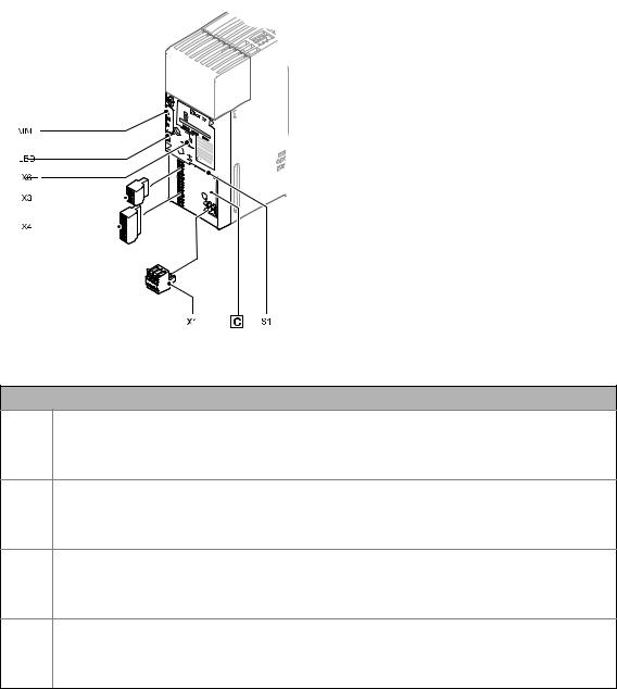
3 |
Overview of terminals |
|
|
|
|
|
|
|
|
|
|
|
|
|
|
|
|
|
|
|
|
|
|
|
|
|
|
|
|
|
|
|
|
|
|
|
|
|
|
|
|
|
|
|
|
|
|
|
|
|
|
|
|||||||||||||||||||||||||||||||
|
Power terminals |
|
|
|
|
|
|
|
|
|
|
|
|
|
|
|
|
|
|
|
|
|
|
|
|
|
|
|
|
|
|
|
|
|
|
|
|
|
|
|
|
|
|
|
|
|
|
|
|
|
|
|
|
|
|
|
|
|
|
|
|||||||||||||||||||||||
|
|
|
|
|
|
|
|
|
|
|
|
|
|
|
|
|
|
|
|
|
|
|
|
|
|
|
|
|
|
|
|
|
|
|
|
|
|
|
|
|
|
|
|
|
|
|
|
|
|
|
|
|
|
|
|
|
|
|
|
|
|
|
|
|
|
|
|
|
|
|
|
|
|
|
|
|
|
|
|
|
|
|
|
|
|
|
|
|
Power range 0.25 |
... |
|
3 kW |
|
|
|
|
|
|
|
|
|
|
|
|
|
|
Power range 3 ... |
22 kW |
|||||||||||||||||||||||||||||||||||||||||||||||||||||||||||
|
|
|
|
|
|
|
|
(Device sizes 1 ... |
3) |
|
|
|
|
|
|
|
|
|
|
|
|
|
|
|
|
|
|
|
|
|
(Device sizes 4 ... |
6) |
|
|
|
|
|
|
|
|
|
|
|
|
|
|
|
|
|
|
|
|
|
|
|
|
|
|
|||||||||||||||||||||||||
|
|
|
|
|
|
|
|
|
|
|
|
|
|
|
|
|
|
|
|
|
|
|
|
|
|
|
|
|
|
|
|
|
|
|
|
|
|
|
|
|
|
|
|
|
|
|
|
|
|
|
|
|
|
|
|
|
|
|
|
|
|
|
|
|
|
|
|
|
|
|
|
|
|
|
|
|
|
|
|
|
|
|
|
|
|
|
|
|
|
|
|
|
|
|
|
|
|
|
|
|
|
|
|
|
|
|
|
|
|
|
|
|
|
|
|
|
|
|
|
|
|
|
|
|
|
|
|
|
|
|
|
|
|
|
|
|
|
|
|
|
|
|
|
|
|
|
|
|
|
|
|
|
|
|
|
|
|
|
|
|
|
|
|
|
|
|
|
|
|
|
|
|
|
|
|
|
|
|
|
|
|
|
|
|
|
|
|
|
|
|
|
|
|
|
|
|
|
|
|
|
|
|
|
|
|
|
|
|
|
|
|
|
|
|
|
|
|
|
|
|
|
|
|
|
|
|
|
|
|
|
|
|
|
|
|
|
|
|
|
|
|
|
|
|
|
|
|
|
|
|
|
|
|
|
|
|
|
|
|
|
|
|
|
|
|
|
|
|
|
|
|
|
|
|
|
|
|
|
|
|
|
|
|
|
|
|
|
|
|
|
|
|
|
|
|
|
|
|
|
|
|
|
|
|
|
|
|
|
|
|
|
|
|
|
|
|
|
|
|
|
|
|
|
|
|
|
|
|
|
|
|
|
|
|
|
|
|
|
|
|
|
|
|
|
|
|
|
|
|
|
|
|
|
|
|
|
|
|
|
|
|
|
|
|
|
|
|
|
|
|
|
|
|
|
|
|
|
|
|
|
|
|
|
|
|
|
|
|
|
|
|
|
|
|
|
|
|
|
|
|
|
|
|
|
|
|
|
|
|
|
|
|
|
|
|
|
|
|
|
|
|
|
|
|
|
|
|
|
|
|
|
|
|
|
|
|
|
|
|
|
|
|
|
|
|
|
|
|
|
|
|
|
|
|
|
|
|
|
|
|
|
|
|
|
|
|
|
|
|
|
|
|
|
|
|
|
|
|
|
|
|
|
|
|
|
|
|
|
|
|
|
|
|
|
|
|
|
|
|
|
|
|
|
|
|
|
|
|
|
|
|
|
|
|
|
|
|
|
|
|
|
|
|
|
|
|
|
|
|
|
|
|
|
|
|
|
|
|
|
|
|
|
|
|
|
|
|
|
|
|
|
|
|
|
|
|
|
|
|
|
|
|
|
|
|
|
|
|
|
|
|
|
|
|
|
|
|
|
|
|
|
|
|
|
|
|
|
|
|
|
|
|
|
|
|
|
|
|
|
|
|
|
|
|
|
|
|
|
|
|
|
|
|
|
|
|
|
|
|
|
|
|
|
|
|
|
|
|
|
|
|
|
|
|
|
|
|
|
|
|
|
|
|
|
|
|
|
|
|
|
|
|
|
|
|
|
|
|
|
|
|
|
|
|
|
|
|
|
|
|
|
|
|
|
|
|
|
|
|
|
|
|
|
|
|
|
|
|
|
|
|
|
|
|
|
|
|
|
|
|
|
|
|
|
|
|
|
|
|
|
|
|
|
|
|
|
|
|
|
|
|
|
|
|
|
|
|
|
|
|
|
|
|
|
|
|
|
|
|
|
|
|
|
|
|
|
|
|
|
|
|
|
|
|
|
|
|
|
|
|
|
|
|
|
|
|
|
|
|
|
|
|
|
|
|
|
|
|
|
|
|
|
|
|
|
|
|
|
|
|
|
|
|
|
|
|
|
|
|
|
|
|
|
|
|
|
|
|
|
|
|
|
|
|
|
|
|
|
|
|
|
|
|
|
|
|
|
|
|
|
|
|
|
|
|
|
|
|
|
|
|
|
|
|
|
|
|
|
|
|
|
|
|
|
|
|
|
|
|
|
|
|
|
|
|
|
|
|
|
|
|
|
|
|
|
|
|
|
|
|
|
|
|
|
|
|
|
|
|
|
|
|
|
|
|
|
|
|
|
|
|
|
|
|
|
|
|
|
|
|
|
|
|
|
|
|
|
|
|
|
|
|
|
|
|
|
|
|
|
|
|
|
|
|
|
|
|
|
|
|
|
|
|
|
|
|
|
|
|
|
|
|
|
|
|
|
|
|
|
|
|
|
|
|
|
|
|
|
|
|
|
|
|
|
|
|
|
|
|
|
|
|
|
|
|
|
|
|
|
|
|
|
|
|
|
|
|
|
|
|
|
|
|
|
|
|
|
|
|
|
|
|
|
|
|
|
|
|
|
|
|
|
|
|
|
|
|
|
|
|
|
|
|
|
|
|
|
|
|
|
|
|
|
|
|
|
|
|
|
|
|
|
|
|
|
|
|
|
|
|
|
|
|
|
|
|
|
|
|
|
|
|
|
|
|
|
|
|
|
|
|
|
|
|
|
|
|
|
|
|
|
|
|
|
|
|
|
|
|
|
|
|
|
|
|
|
|
|
|
|
|
|
|
|
|
|
|
|
|
|
|
|
|
|
|
|
|
|
|
|
|
|
|
|
|
|
|
|
|
|
|
|
|
|
|
|
|
|
|
|
|
|
|
|
|
|
|
|
|
|
|
|
|
|
|
|
|
|
|
|
|
|
|
|
|
|
|
|
|
|
|
|
|
|
|
|
|
|
|
|
|
|
|
|
|
|
|
|
|
|
|
|
|
|
|
|
|
|
|
|
|
|
|
|
|
|
|
|
|
|
|
|
|
|
|
|
|
|
|
|
|
|
|
|
|
|
|
|
|
|
|
|
|
|
|
|
|
|
|
|
|
|
|
|
|
|
|
|
|
|
|
|
|
|
|
|
|
|
|
|
|
|
|
|
|
|
|
|
|
|
|
|
|
|
|
|
|
|
|
|
|
|
|
|
|
|
|
|
|
|
|
|
|
|
|
|
|
|
|
|
|
|
|
|
|
|
|
|
|
|
|
|
|
|
|
|
|
|
|
|
|
|
|
|
|
|
|
|
|
|
|
|
|
|
|
|
|
|
|
|
|
|
|
|
|
|
|
|
|
|
|
|
|
|
|
|
|
|
|
|
|
|
|
|
|
|
|
|
|
|
|
|
|
|
|
|
|
|
|
|
|
|
|
|
|
|
|
|
|
|
|
|
|
|
|
|
|
|
|
|
|
|
|
|
|
|
|
|
|
|
|
|
|
|
|
|
|
|
|
|
|
|
|
|
|
|
|
|
|
|
|
|
|
|
|
|
|
|
|
|
|
|
|
|
|
|
|
|
|
|
|
|
|
|
|
|
|
|
|
|
|
|
|
|
|
|
|
|
|
|
|
|
|
|
|
|
|
|
|
|
|
|
|
|
|
|
|
|
|
|
|
|
|
|
|
|
|
|
|
|
|
|
|
|
|
|
|
|
|
|
|
|
|
|
|
|
|
|
|
|
|
|
|
|
|
|
|
|
|
|
|
|
|
|
|
|
|
|
|
|
|
|
|
|
|
|
|
|
|
|
|
|
|
|
|
|
|
|
|
|
|
|
|
|
|
|
|
|
|
|
|
|
|
|
|
|
|
|
|
|
|
|
|
|
|
|
|
|
|
|
|
|
|
|
|
|
|
|
|
|
|
|
|
|
|
|
|
|
|
|
|
|
|
|
|
|
|
|
|
|
|
|
|
|
|
|
|
|
|
|
|
|
|
|
|
|
|
|
|
|
|
|
|
|
|
|
|
|
|
|
|
|
|
|
|
|
|
|
|
|
|
|
|
|
|
|
|
|
|
|
|
|
|
|
|
|
|
|
|
|
|
|
|
|
|
|
|
|
|
|
|
|
|
|
|
|
|
|
|
|
|
|
|
|
|
|
|
|
|
|
|
|
|
|
|
|
|
|
|
|
|
|
|
|
|
|
|
|
|
|
|
|
|
|
|
|
|
|
|
|
|
|
|
|
|
|
|
|
|
|
|
|
|
|
|
|
|
|
|
|
|
|
|
|
|
|
|
|
|
|
|
|
|
|
|
|
|
|
|
|
|
|
|
|
|
|
|
|
|
|
|
|
|
|
|
|
|
|
|
|
|
|
|
|
|
|
|
|
|
|
|
|
|
|
|
|
|
|
|
|
|
|
|
|
|
|
|
|
|
|
|
|
|
|
|
|
|
|
|
|
|
|
|
|
|
|
|
|
|
|
|
|
|
|
|
|
|
|
|
|
|
|
|
|
|
|
|
|
|
|
|
|
|
|
|
|
|
|
|
|
|
|
|
|
|
|
|
|
|
|
|
|
|
|
|
|
|
|
|
|
|
|
|
|
|
|
|
|
|
|
|
|
|
|
|
|
|
|
|
|
|
|
|
|
|
|
|
|
|
|
|
|
|
|
|
|
|
|
|
|
|
|
|
|
|
|
|
|
|
|
|
|
|
|
|
|
|
|
|
|
|
|
|
|
|
|
|
|
|
|
|
|
|
|
|
|
|
|
|
|
|
|
|
|
|
|
|
|
|
|
|
|
|
|
|
|
|
|
|
|
|
|
|
|
|
|
|
|
|
|
|
|
|
|
|
|
|
|
|
|
|
|
|
|
|
|
|
|
|
|
|
|
|
|
|
|
|
|
|
|
|
|
|
|
|
|
|
|
|
|
|
|
|
|
|
|
|
|
|
|
|
|
|
|
|
|
|
|
|
|
|
|
|
|
|
|
|
|
|
|
|
|
|
|
|
|
|
|
|
|
|
|
|
|
|
|
|
|
|
|
|
|
|
|
|
|
|
|
|
|
|
|
|
|
|
|
|
|
|
|
|
|
|
|
|
|
|
|
|
|
|
|
|
|
|
|
|
|
|
|
|
|
|
|
|
|
|
|
|
|
|
|
|
|
|
|
|
|
|
|
|
|
|
|
|
|
|
|
|
|
|
|
|
|
|
|
|
|
|
|
|
|
|
|
|
|
|
|
|
|
|
|
|
|
|
|
|
|
|
|
|
|
|
|
|
|
|
|
|
|
|
|
|
|
|
|
|
|
|
|
|
|
|
|
|
|
|
|
|
|
|
|
|
|
|
|
|
|
|
|
|
|
|
|
|
|
|
|
|
|
|
|
|
|
|
|
|
|
|
|
|
|
|
|
|
|
|
|
|
|
|
|
|
|
|
|
|
|
|
|
|
|
|
|
|
|
|
|
|
|
|
|
|
|
|
|
|
|
|
|
|
|
|
|
|
|
|
|
|
|
|
|
|
|
|
|
|
|
|
|
|
|
|
|
|
|
|
|
|
|
|
|
|
|
|
|
|
|
|
|
|
|
|
|
|
|
|
|
|
|
|
|
|
|
|
|
|
|
|
|
|
|
|
|
|
|
|
|
|
|
|
|
|
|
|
|
|
|
|
|
|
|
|
|
|
|
|
|
|
|
|
|
|
|
|
|
|
|
|
|
|
|
|
|
|
|
|
|
|
|
|
|
|
|
|
|
|
|
|
|
|
|
|
|
|
Power range 30 ... 45 kW |
X80 |
Terminal strip for drive-based safety "safe torque |
(Device size 7) |
|
off (STO)" (option) |
|
X100 |
Mains/DC-bus voltage for 400 V devices |
|
X101 |
Relay output |
|
|
• AC 250 V, 3 A |
|
|
• DC 24V, 2A |
|
|
• DC 240 V, 0.16 A |
|
X105 |
Motor/external brake resistor |
|
X106 |
Motor temperature monitoring |
|
IT |
Contact screws for interference suppression (on |
|
|
the supply side and on the on the motor side) |
|
|
• Before using the controller in the IT system, |
|
|
loose both contact screws. |
|
|
• Please observe the notes in the hardware |
|
|
manual and in mounting instructions of the |
|
|
controller and filters. |
|
MCI |
Slot for communication module |
|
|
• MCI = abbreviation for "Module |
|
|
Communication Interface" |
|
Sticker with warning |
|
|
|
|
|
|
|
|
|
|
|
|
|
9 |
|
|
|
|
|
|
|
|
|
|
|
|
|
Lenze · 8400 StateLine · Operating instructions · from Firmware V06.00 · DMS 1.2 EN · 12/2012 · TD05 |
||||||||||||
3 Overview of terminals
_ _ _ _ _ _ _ _ _ _ _ _ _ _ _ _ _ _ _ _ _ _ _ _ _ _ _ _ _ _ _ _ _ _ _ _ _ _ _ _ _ _ _ _ _ _ _ _ _ _ _ _ _ _ _ _ _ _ _ _ _ _ _ _
Control terminals
|
|
|
|
|
|
|
|
|
|
|
|
|
|
|
|
|
|
|
|
|
|
|
|
|
|
|
|
|
|
|
|
|
|
|
|
|
X1 |
CANopen connection |
||
|
|
|
|
|
|
|
|
|
|
|
|
|
|
|
|
|
|
|
|
|
|
|
|
|
|
|
|
|
|
|
|
|
|
|
|
|
||||
|
|
|
|
|
|
|
|
|
|
|
|
|
|
|
|
|
|
|
|
|
|
|
|
|
|
|
|
|
|
|
|
|
|
|
|
|
|
|
|
|
|
|
|
|
|
|
|
|
|
|
|
|
|
|
|
|
|
|
|
|
|
|
|
|
|
|
|
|
|
|
|
|
|
|
|
|
|
S1 |
CANopen settings |
||
|
|
|
|
|
|
|
|
|
|
|
|
|
|
|
|
|
|
|
|
|
|
|
|
|
|
|
|
|
|
|
|
|
|
|
|
|
|
(Bus terminating resistor, baud rate and node |
||
|
|
|
|
|
|
|
|
|
|
|
|
|
|
|
|
|
|
|
|
|
|
|
|
|
|
|
|
|
|
|
|
|
|
|
|
|
|
address) |
||
|
|
|
|
|
|
|
|
|
|
|
|
|
|
|
|
|
|
|
|
|
|
|
|
|
|
|
|
|
|
|
|
|
|
|
|
|
X3 |
|
• Analog inputs/outputs |
|
|
|
|
|
|
|
|
|
|
|
|
|
|
|
|
|
|
|
|
|
|
|
|
|
|
|
|
|
|
|
|
|
|
|
|
|
|
|
|
• 10 V reference voltage |
|
|
|
|
|
|
|
|
|
|
|
|
|
|
|
|
|
|
|
|
|
|
|
|
|
|
|
|
|
|
|
|
|
|
|
|
|
|
|
|||
|
|
|
|
|
|
|
|
|
|
|
|
|
|
|
|
|
|
|
|
|
|
|
|
|
|
|
|
|
|
|
|
|
|
|
|
|
|
Note: Voltage input A1U and current input A1I |
||
|
|
|
|
|
|
|
|
|
|
|
|
|
|
|
|
|
|
|
|
|
|
|
|
|
|
|
|
|
|
|
|
|
|
|
|
|
|
|||
|
|
|
|
|
|
|
|
|
|
|
|
|
|
|
|
|
|
|
|
|
|
|
|
|
|
|
|
|
|
|
|
|
|
|
|
|
|
must not be used simultaneously! |
||
|
|
|
|
|
|
|
|
|
|
|
|
|
|
|
|
|
|
|
|
|
|
|
|
|
|
|
|
|
|
|
|
|
|
|
|
|
X4 |
|
• Digital inputs/outputs |
|
|
|
|
|
|
|
|
|
|
|
|
|
|
|
|
|
|
|
|
|
|
|
|
|
|
|
|
|
|
|
|
|
|
|
|
|
|
|
|
(according to IEC 61131-2, type 1) |
|
|
|
|
|
|
|
|
|
|
|
|
|
|
|
|
|
|
|
|
|
|
|
|
|
|
|
|
|
|
|
|
|
|
|
|
|
|
|
|||
|
|
|
|
|
|
|
|
|
|
|
|
|
|
|
|
|
|
|
|
|
|
|
|
|
|
|
|
|
|
|
|
|
|
|
|
|
|
|
• External 24 V supply voltage |
|
|
|
|
|
|
|
|
|
|
|
|
|
|
|
|
|
|
|
|
|
|
|
|
|
|
|
|
|
|
|
|
|
|
|
|
|
|
|
|||
|
|
|
|
|
|
|
|
|
|
|
|
|
|
|
|
|
|
|
|
|
|
|
|
|
|
|
|
|
|
|
|
|
|
|
|
|
|
|
(for control electronics) |
|
|
|
|
|
|
|
|
|
|
|
|
|
|
|
|
|
|
|
|
|
|
|
|
|
|
|
|
|
|
|
|
|
|
|
|
|
|
|
|||
|
|
|
|
|
|
|
|
|
|
|
|
|
|
|
|
|
|
|
|
|
|
|
|
|
|
|
|
|
|
|
|
|
|
|
|
|
|
|
• 24 V voltage output |
|
|
|
|
|
|
|
|
|
|
|
|
|
|
|
|
|
|
|
|
|
|
|
|
|
|
|
|
|
|
|
|
|
|
|
|
|
|
X6 |
Diagnostic interface (DIAG) |
||
|
|
|
|
|
|
|
|
|
|
|
|
|
|
|
|
|
|
|
|
|
|
|
|
|
|
|
|
|
|
|
|
|
|
|
|
|
|
|
• For keypad ( 14) or PC connection ( 18) |
|
|
|
|
|
|
|
|
|
|
|
|
|
|
|
|
|
|
|
|
|
|
|
|
|
|
|
|
|
|
|
|
|
|
|
|
|
|
|
|||
|
|
|
|
|
|
|
|
|
|
|
|
|
|
|
|
|
|
|
|
|
|
|
|
|
|
|
|
|
|
|
|
|
|
|
|
|
MMI |
Slot for memory module ( 19) |
||
|
|
|
|
|
|
|
|
|
|
|
|
|
|
|
|
|
|
|
|
|
|
|
|
|
|
|
|
|
|
|
|
|
|
|
|
|
|
|
• MMI = abbreviation for "Memory Module |
|
|
|
|
|
|
|
|
|
|
|
|
|
|
|
|
|
|
|
|
|
|
|
|
|
|
|
|
|
|
|
|
|
|
|
|
|
|
|
|
Interface" |
|
|
|
|
|
|
|
|
|
|
|
|
|
|
|
|
|
|
|
|
|
|
|
|
|
|
|
|
|
|
|
|
|
|
|
|
|
|
|
|
|
|
|
|
|
|
|
|
|
|
|
|
|
|
|
|
|
|
|
|
|
|
|
|
|
|
|
|
|
|
|
|
|
|
|
|
|
|
|
LED |
Status displays of the device status ( 44) |
||
|
|
|
|
|
|
|
|
|
|
|
|
|
|
|
|
|
|
|
|
|
|
|
|
|
|
|
|
|
|
|
|
|
|
|
|
|
|
|
|
&$1 581 |
|
|
|
|
|
|
|
|
|
|
|
|
|
|
|
|
|
|
|
|
|
|
|
|
|
|
|
|
|
|
|
|
|
|
|
|
|
|
|
|
|
|
|
|
|
|
|
|
|
|
|
|
|
|
|
|
|
|
|
|
|
|
|
|
|
|
|
|
|
|
|
|
|
|
|
|
|
|
|
|
|
&$1 (55 |
|
|
|
|
|
|
|
|
|
|
|
|
|
|
|
|
|
|
|
|
|
|
|
|
|
|
|
|
|
|
|
|
|
|
|
|
|
|
|
|
|
|
|
|
|
|
|
|
|
|
|
|
|
|
|
|
|
|
|
|
|
|
|
|
|
|
|
|
|
|
|
|
|
|
|
|
|
|
|
|||
|
|
|
|
|
|
|
|
|
|
|
|
|
|
|
|
|
|
|
|
|
|
|
|
|
|
|
|
|
|
|
|
|
|
|
|
|
|
|
|
'59 5'< |
|
|
|
|
|
|
|
|
|
|
|
|
|
|
|
|
|
|
|
|
|
|
|
|
|
|
|
|
|
|
|
|
|
|
|
|
|
|
|
|
|
|
|
|
|
|
|
|
|
|
|
|
|
|
|
|
|
|
|
|
|
|
|
|
|
|
|
|
|
|
|
|
|
|
|
|
|
|
|
|
|
'59 (55 |
|
|
|
|
|
|
|
|
|
|
|
|
|
|
|
|
|
|
|
|
|
|
|
|
|
|
|
|
|
|
|
|
|
|
|
|
|
|
|
|
|
Description of the warning signs
Long discharge time!
All power terminals remain live for some minutes after mains disconnection! The time is given below the warning symbol on the device.
High leakage current!
Carry out fixed installation and PE connection in accordance with EN 61800-5-1!
Electrostatic sensitive devices!
Before working on the device, the staff must ensure to be free of electrostatic charge!
HotRisksurface!of burns!
Hot surfaces should not be touched without wearing protective gloves.
10 |
Lenze · 8400 StateLine · Operating instructions · from Firmware V06.00 · DMS 1.2 EN · 12/2012 · TD05 |
4 Connection/wiring of the controller
_ _ _ _ _ _ _ _ _ _ _ _ _ _ _ _ _ _ _ _ _ _ _ _ _ _ _ _ _ _ _ _ _ _ _ _ _ _ _ _ _ _ _ _ _ _ _ _ _ _ _ _ _ _ _ _ _ _ _ _ _ _ _ _
4 |
Connection/wiring of the controller |
|
|
1/N/PE AC 230 V |
|
|
|
3/PE AC 400 V/500 V |
|
|
|||||||||
L1 |
|
|
|
|
|
|
|
|
L1 |
|
|
|
|
|
|
|
|
N |
|
|
|
|
|
|
|
|
L2 |
|
|
|
|
|
|
|
|
PE |
|
|
|
|
|
|
|
|
L3 |
|
|
|
|
|
|
|
|
|
|
|
|
|
|
|
|
|
N |
|
|
|
|
|
|
|
|
|
|
|
|
|
|
|
|
|
PE |
|
|
|
|
|
|
|
|
|
|
|
|
|
F1 |
|
|
|
|
|
|
F1…F3 |
|
|
|
||
|
F2 |
|
|
|
K |
|
|
|
|
F4 |
|
|
|
K |
|
|
|
|
|
|
|
|
Z |
|
|
|
|
|
|
|
|
Z |
|
|
|
|
O |
|
|
|
|
|
|
|
|
O |
|
|
|
|
|
|
|
K |
I |
PE |
|
|
|
L1 |
N |
|
K |
I |
PE |
|
|
|
L1 L2 |
L3 +UG -UG |
|
|
|
|
|
|
|
X100 |
|
|
|
|
|
|
|
|
X100 |
|
|
|
Rb |
|
|
|
|
|
|
|
|
Rb |
|
|
|
|
|
|
|
|
|
|
E84AVSCxxxx2... |
|
|
|
|
E84AVSCxxxx4... |
|
||||||||
|
K |
|
|
|
|
|
|
|
|
K |
|
|
|
|
|
|
|
|
|
X105 |
|
|
X106 |
|
|
X105 |
|
|
X106 |
||||||
|
|
Rb1 Rb2 |
U |
V |
W |
PE |
T1 |
T2 |
|
|
Rb1 Rb2 |
U |
V |
W |
PE |
T1 |
T2 |
|
|
|
|
|
|
|
|
|
|
|
|
|
|
|
|
|
|
|
|
|
|
|
|
|
|
|
|
|
|
|
|
|
|
||
|
|
Rb1 Rb2 |
|
|
|
|
|
|
|
|
Rb1 Rb2 |
|
|
|
|
|
|
|
|
Rb |
|
|
|
|
|
|
|
|
Rb |
|
|
|
|
|
|
|
|
|
|
|
|
|
|
|
|
|
|
|
|
|
|
|
|
|
|
|
|
|
|
|
|
|
|
|
|
|
|
|
|
||
|
|
M |
|
|
|
|
|
|
M |
|
|
|
|
||||
|
|
3~ |
|
|
|
|
|
|
3~ |
|
|
|
|
||||
|
|
|
|
|
|
|
|
|
|
|
|
|
|
|
|
||
|
|
|
|
|
|
|
|
|
|
|
|
|
|
|
|
||
|
|
|
|
PTC |
|
|
|
|
|
|
|
|
PTC |
|
|
|
|
|
|
|
M |
|
|
|
|
|
|
|
M |
|
|
|
|
||
|
|
|
3~ |
|
|
|
|
|
|
|
3~ |
|
|
|
|
||
|
|
|
|
|
|
|
|
|
|
|
|
|
|
|
|
||
|
|
|
|
|
|
|
|
|
|
|
|
|
|
|
|
|
|
[4-1] Wiring of the power and motor terminals of 230V devices (on the left) and 400V devices (on the right)
($96&[[[[[ |
|
X3 - Analog terminals |
|||
|
|
|
|||
|
9 P$ |
; |
|
A1U |
Main speed setpoint |
|
$5 |
|
N |
|
10 V ≡ 100 % reference speed ≡ 1500 rpm |
|
$8 |
|
9 |
|
(applies to 4-pole asynchronous motors) |
|
$, |
|
|
||
|
|
|
|
||
|
*$ |
|
|
O1U |
Actual speed value |
*1'$ |
2 8 |
|
|
|
10 V ≡ 100 % reference speed ≡ 1500 rpm |
|
|
|
|
|
|
9 |
|
; |
|
X4 - Digital terminals |
|
( |
9 '& |
|
|
||
|
24E |
External supply - control electronics (optional) |
|||
|
|
||||
|
, |
|
|
||
|
|
|
|
|
|
|
5)5 |
|
|
RFR |
Controller enable / Reset of error message |
|
', |
|
|
DI1 |
Fixed speed setpoint 1 (40 % of the reference speed) |
|
', |
|
|
||
|
', |
|
|
DI2 |
Fixed speed setpoint 2 (60 % of the reference speed) |
|
', |
|
|
||
|
|
|
|
|
|
|
'2 |
|
|
DI3 |
Manual DC-injection braking |
|
*,2 |
|
|
DI4 |
Change of direction of rotation |
|
|
|
|
||
*1' ,2 |
; |
|
DO1 |
Status "Drive is ready" |
|
|
&20 |
|
X101 - relay output |
||
|
1& |
|
|
||
|
12 |
|
|
COM/NO |
Status "Error is pending" |
|
|
|
|
||
[4-2] Wiring of the control terminals / preconfigured assignment (Lenze setting)
Lenze · 8400 StateLine · Operating instructions · from Firmware V06.00 · DMS 1.2 EN · 12/2012 · TD05 |
11 |

5 Before commissioning
5.1Selection of the appropriate commissioning tool
_ _ _ _ _ _ _ _ _ _ _ _ _ _ _ _ _ _ _ _ _ _ _ _ _ _ _ _ _ _ _ _ _ _ _ _ _ _ _ _ _ _ _ _ _ _ _ _ _ _ _ _ _ _ _ _ _ _ _ _ _ _ _ _
5 Before commissioning
Being a component of a machine which includes a speed-variable drive system, the controller needs to be adjusted to its drive task. The controller is adjusted by changing parameters which are saved in the memory module. The parameters can be accessed by keypad, by the »EASY Starter« or by the »Engineer«. Access is also possible by a master control via fieldbus communication, e.g. via CAN bus.
Danger!
In general, changing a parameter causes an immediate response in the controller!
This may lead to undesirable behaviour on the motor shaft if the controller has been enabled! Setpoint sources, for instance, may switch over all of a sudden (e.g. when configuring the signal source for the main setpoint).
Certain device commands or settings which may cause critical states of drive behaviour constitute exceptions. Such parameter changes are only possible if the controller is inhibited. Otherwise, a corresponding error message will be issued.
5.1Selection of the appropriate commissioning tool
There are several possibilities for commissioning the 8400 StateLine controller:
Commissioning with keypad X400 (diagnosis terminal X400)
The keypad is an alternative to the PC for the local operation, parameterisation, and diagnostics in a simple manner. The keypad is especially suitable for test or demonstration purposes and if only a few parameters have to be adapted.
Commissioning with PC and »EASY Starter«
The »EASY Starter« is a Lenze tool for easy online diagnostics, parameter setting and commissioning of the controller.
Commissioning with PC and »Engineer«
The »Engineer« is a Lenze engineering software for parameter setting across all devices, configuring and diagnosing individual components (as for instance controllers, industrial PCs, motors, I/O systems) and machine control systems.
12 |
Lenze · 8400 StateLine · Operating instructions · from Firmware V06.00 · DMS 1.2 EN · 12/2012 · TD05 |
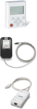
5 Before commissioning
5.1Selection of the appropriate commissioning tool
_ _ _ _ _ _ _ _ _ _ _ _ _ _ _ _ _ _ _ _ _ _ _ _ _ _ _ _ _ _ _ _ _ _ _ _ _ _ _ _ _ _ _ _ _ _ _ _ _ _ _ _ _ _ _ _ _ _ _ _ _ _ _ _
Tip!
The Engineering tools »EASY Starter« and »Engineer StateLevel« are provided free of charge in the internet:
http://www.Lenze.com Download Software downloads
For communication between PC and controller, the USB diagnostic adapter can be used for instance (see the following accessories overview).
Accessories for commissioning
Version |
Features |
Product key |
|
Keypad X400 |
• Menu navigation |
EZAEBK1001 |
|
|
• Backlighted graphic display for comfortably representing |
|
|
|
information |
|
|
|
• 4 navigation keys, 2 context-sensitive keys |
|
|
|
• Adjustable RUN/STOP function |
|
|
|
• Hot-plug capable |
|
|
|
• Can be used for L-force Inverter Drives 8400 and Servo |
|
|
|
Drives 9400 |
|
|
|
|
|
|
Diagnosis terminal X400 |
• Keypad X400 in a robust housing |
EZAEBK2001 |
|
|
• Also suitable for installation into the control cabinet door |
|
|
|
• incl. 2.5 m cable |
|
|
|
• Enclosure IP20, in case of front installation in control |
|
|
|
cabinet IP65 |
|
|
|
|
|
|
USB diagnostic adapter |
• Input-side voltage supply via USB connection from PC |
E94AZCUS |
|
|
• Output-side voltage supply via the diagnostic interface of |
|
|
|
the controller |
|
|
|
• Diagnostic LED |
|
|
|
• Electrical isolation of PC and controller |
|
|
|
• Hot-plug capable |
|
|
|
|
|
|
Connecting cable for |
2.5 m length |
EWL0070 |
|
USB diagnostic adapter |
|
|
|
5 m length |
EWL0071 |
||
|
|||
|
|
|
|
|
10 m length |
EWL0072 |
|
|
|
|
Lenze · 8400 StateLine · Operating instructions · from Firmware V06.00 · DMS 1.2 EN · 12/2012 · TD05 |
13 |
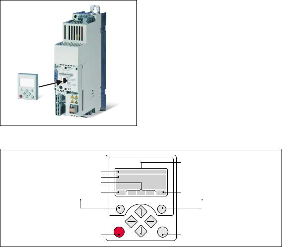
5 Before commissioning
5.2General notes on parameters
_ _ _ _ _ _ _ _ _ _ _ _ _ _ _ _ _ _ _ _ _ _ _ _ _ _ _ _ _ _ _ _ _ _ _ _ _ _ _ _ _ _ _ _ _ _ _ _ _ _ _ _ _ _ _ _ _ _ _ _ _ _ _ _
5.2General notes on parameters
All parameters for controller parameterising or monitoring are saved as so-called "codes".
•The codes are numbered and indicated by the prefix "C" before the code, e.g. "C00002".
•Moreover, each code has a name and specific attributes, as for example access type (reading, writing), data type, limit values and default setting ("Lenze setting").
•For the sake of clarity, some codes contain "subcodes" for saving parameters. This Manual uses a slash "/" as a separator between code and subcode, e.g. C00118/3".
•According to their functionality, the parameters are divided into three groups:
•Setting parameters: For specifying setpoints and for setting device / monitoring functions.
•Configuration parameters: For configuring signal connections and terminal assignments.
•Diagnostic/display parameters: For displaying device-internal process factors, current actual values and status messages.
5.2.1Changing the parameterisation with the keypad
The keypad is simply plugged on the diagnostic interface X6 ("DIAG") at the front of the standard device.
Plugging and unplugging the keypad is possible during operation.
Keypad display and control elements
|
|
|
/&' GLVSOD\ |
+HDGOLQH |
|
|
|
7ULSOH OLQH GLVSOD\ |
|
|
|
'HYLFH VWDWH |
|
|
|
&XUUHQW IXQFWLRQ |
|
|
&XUUHQW IXQFWLRQ |
OHIW IXQFWLRQ NH\ |
|
|
ULJKW IXQFWLRQ NH\ |
,Q PDQXDO FRQWURO PRGH |
WXST |
VYR |
,Q PDQXDO FRQWURO PRGH |
6WRS PRWRU |
|
|
6WDUW PRWRU |
14 |
Lenze · 8400 StateLine · Operating instructions · from Firmware V06.00 · DMS 1.2 EN · 12/2012 · TD05 |
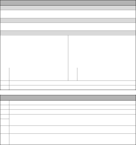
5 Before commissioning
5.2General notes on parameters
_ _ _ _ _ _ _ _ _ _ _ _ _ _ _ _ _ _ _ _ _ _ _ _ _ _ _ _ _ _ _ _ _ _ _ _ _ _ _ _ _ _ _ _ _ _ _ _ _ _ _ _ _ _ _ _ _ _ _ _ _ _ _ _
LCD display
Headline
In the menu level: Menu name
In the parameter level: Parameter name
Three-part display
In the menu level: List of available menus
In the parameter level: Code/subcode and setting or actual value
Device status
|
Controller is switched on |
|
Pulse inhibit is active |
|
Controller is enabled |
|
System fault is active |
|
Controller is inhibited |
|
"Fault" device status is active |
|
Quick stop is active |
|
Device status "Trouble" active |
|
Current limit exceeded |
|
Device status "TroubleQSP" active |
|
Speed controller 1 in the limitation |
|
A warning is indicated |
Function - left function key |
Function - right function key |
||
Change parameter setting |
Accept change in the controller |
||
|
(change to editing mode) |
|
(no saving with mains failure protection ) |
Back to main menu |
Abort (discard change) |
||
Parameter can only be changed when the controller is inhibited.
Save all parameter settings in the memory module safe against mains failure
Control elements
Execute the function assigned to the function key (see LCD display)
Execute the stop function set in C00469 (Lenze setting: Inhibit controller)
Deactivate stop function again (Lenze setting: Enable controller again)
In the menu level: Select menu/submenu
In the parameter level: Select parameter
In the editing mode: Change marked digits or select list entry
In the menu level: Select submenu/change to parameter level In the editing mode: Cursor to the right
In the menu level: One menu level higher (if available) In the parameter level: Back to menu level
In the editing mode: Cursor to the left
Menu structure
In the keypad, the parameters are classified into various menus and submenus.
•The USER menu includes a selection of frequently used parameters. ( 20)
•The Code list contains all parameters.
•The Go to param function enables you to reach the corresponding parameter directly.
•The Logbook logs all errors and their chronological history.
•The Diagnostics menu contains diagnostic/display parameters for displaying device-internal process factors, current actual values and status messages.
Lenze · 8400 StateLine · Operating instructions · from Firmware V06.00 · DMS 1.2 EN · 12/2012 · TD05 |
15 |

5 Before commissioning
5.2General notes on parameters
_ _ _ _ _ _ _ _ _ _ _ _ _ _ _ _ _ _ _ _ _ _ _ _ _ _ _ _ _ _ _ _ _ _ _ _ _ _ _ _ _ _ _ _ _ _ _ _ _ _ _ _ _ _ _ _ _ _ _ _ _ _ _ _
General operation |
|
|
|
|
1. |
Par1 8400 StateLine C |
|
1. Use the / navigation keys to select the |
|
|
|
|
desired menu. |
|
|
USER - Menu |
|
|
• Use the / navigation keys to reach a |
|
Code list |
|
|
|
|
Go To Param |
|
|
higher/lower menu level. |
|
SAVE |
|
|
• Use the function key to return to the |
|
|
|
|
main menu. |
|
Load Lenze setting |
|
2. |
2. Use the / navigation keys to select the |
|
C00002/001 |
|
|
|
|
|
|
|
parameter to be set within a submenu. |
|
Off / Finished |
|
|
3. In order to select another subcode in case of a |
|
EDIT |
|
|
parameter with subcodes: |
|
|
|
|
• Press the navigation key to change tot he |
|
Fixed setpoint 1 |
|
|
editing mode for the subcode. |
|
C00039/001 |
|
3. |
• Use the navigation keys to set the desired |
|
40.00 % |
|
|
subcode. |
|
|
|
|
|
|
EDIT |
|
|
4. Use the function key to switch over to the |
|
|
|
|
editing mode. |
|
Fixed setpoint 2 |
|
|
5. Use the navigation keys to set the desired value. |
|
C00039/002 |
|
|
6. Use the function key to accept the change |
|
|
|
|
|
|
60.00 % |
|
|
and to leave the editing mode. |
4. EDIT |
|
|
• Use the function key to leave the editing |
|
|
|
|
|
mode without accepting the change. |
|
Fixed setpoint 2 |
|
|
|
|
C00039/002 |
|
5. |
|
|
60.00 % |
|
|
|
|
ESC |
OK |
|
|
|
|
|
6. |
|
[5-1] Example: Change parameter with the keypad |
|
|
||
16 |
Lenze · 8400 StateLine · Operating instructions · from Firmware V06.00 · DMS 1.2 EN · 12/2012 · TD05 |

5 Before commissioning
5.2General notes on parameters
_ _ _ _ _ _ _ _ _ _ _ _ _ _ _ _ _ _ _ _ _ _ _ _ _ _ _ _ _ _ _ _ _ _ _ _ _ _ _ _ _ _ _ _ _ _ _ _ _ _ _ _ _ _ _ _ _ _ _ _ _ _ _ _
Multilingualism
All texts displayed in the keypad are in English.
From version 11.00.00 onwards, the most important menus as well as diagnostic and configuration parameters can are also available in German and French. To set a different language, select the Language selection menu item in the main menu of the keypad.
Language |
|
|
• The multilingual texts are stored in the |
|
|
controller and do not have to be loaded into the |
|
|
|
|
|
English |
|
|
device. |
|
|
||
Deutsch |
|
|
• For reasons of disc space, only the most |
Français |
|
|
|
|
|
||
ESC |
OK |
important menus and parameters as well as the |
|
|
|
|
error messages are available in several |
|
|
|
languages. |
|
|
|
|
User level
From version 12.00.00, the extension of the menus, submenus and codes shown in the keypad can be adapted by selecting the "user level" in C00001/1:
•Standard user level (Lenze setting): Only the most important menus and codes are displayed in the keypad.
•Expert user level: All menus and codes are displayed in the keypad.
•Service user level: Only for the purpose of service (Lenze Service).
After changing the user level, the menus in the keypad are restructured according to the selected user level. The parameters of plugged-in communication module are always shown completely independent of the set user level.
Lenze · 8400 StateLine · Operating instructions · from Firmware V06.00 · DMS 1.2 EN · 12/2012 · TD05 |
17 |

5 Before commissioning
5.2General notes on parameters
_ _ _ _ _ _ _ _ _ _ _ _ _ _ _ _ _ _ _ _ _ _ _ _ _ _ _ _ _ _ _ _ _ _ _ _ _ _ _ _ _ _ _ _ _ _ _ _ _ _ _ _ _ _ _ _ _ _ _ _ _ _ _ _
5.2.2Change parameter settings with PC and Lenze software
The USB diagnostic adapter, for instance, can be used for the communication between the PC (including the »EASY Starter« or » Engineer« software) and the controller, see the following illustration. The USB diagnostic adapter is the connection between the PC (free USB port) and the controller (X6 diagnostic interface).
[5-2] Exemplary constellation for parameterising the controller
The All parameters tab in the »EASY Starter« and the »Engineer« provides a quick access to all parameters of the controller.
The given categories ( ) and subcategories ( ) correspond 1:1 to the menus and submenus of the keypad:
[5-3] All parameters tab in the »EASY Starter«
Moreover, the »Engineer« provides a commissioning interface on the Application parameters tab where you can commission the application in a few steps.
Detailed information on how to handle the »Engineer« can be found in the integrated online help that you can call with the [F1] function key.
18 |
Lenze · 8400 StateLine · Operating instructions · from Firmware V06.00 · DMS 1.2 EN · 12/2012 · TD05 |

5 Before commissioning
5.2General notes on parameters
_ _ _ _ _ _ _ _ _ _ _ _ _ _ _ _ _ _ _ _ _ _ _ _ _ _ _ _ _ _ _ _ _ _ _ _ _ _ _ _ _ _ _ _ _ _ _ _ _ _ _ _ _ _ _ _ _ _ _ _ _ _ _ _
5.2.3Save parameter settings in the memory module safe against mains failure
Controller parameter changes via the EASY Starter /»Engineer«, the keypad, or a master control via fieldbus communication will be lost after mains switching of the controller unless the settings have been explicitly saved to the integrated memory module.
General information
•In the delivery state, the Lenze setting of the parameters has been saved to the integrated memory module.
•When the device or the external 24 V voltage supply is switched on, all parameters are automatically loaded from the memory module into the main memory of the controller.
•Full functionality of the memory module is even provided if the power supply has been switched off and only the electronic components of the controller are externally supplied by a 24 V DC voltage, e.g. via the X4/24E terminal.
Save parameters
•Using the keypad, you can press function key to save the parameter settings.
•The »EASY Starter«/»Engineer« serves to execute the saving via the icon  in the toolbar or via the device command "Save all parameter sets" (C00002/11 = "1: On / start").
•The storage process may take a couple of seconds. After the device command has been called in C00002/11, dynamic status information ("Work in progress 20%" "Work in progress 40%" "Work in progress 60%", etc.) is returned.
Note!
In order to prevent data inconsistencies during the saving process:
•Do not switch off the supply voltage!
•Do not remove the memory module from the device!
Lenze · 8400 StateLine · Operating instructions · from Firmware V06.00 · DMS 1.2 EN · 12/2012 · TD05 |
19 |

5 Before commissioning
5.2General notes on parameters
_ _ _ _ _ _ _ _ _ _ _ _ _ _ _ _ _ _ _ _ _ _ _ _ _ _ _ _ _ _ _ _ _ _ _ _ _ _ _ _ _ _ _ _ _ _ _ _ _ _ _ _ _ _ _ _ _ _ _ _ _ _ _ _
5.2.4User menu for quick access to frequently used parameters
When a system is installed, parameters must be changed time and again until the system runs satisfactorily. The user menu of a device contains a selection of frequently used parameters to be able to access and change these parameters quickly.
|
Parameter |
Name |
Lenze setting |
|
|
C00051 |
Display of actual speed value |
- |
|
|
C00053 |
Display of DC-bus voltage |
- |
|
|
C00054 |
Display of motor current |
- |
|
|
C00061 |
Display of heatsink temperature |
- |
|
|
C00137 |
Display of device status |
- |
|
|
C00166/3 |
Display of current error message |
- |
|
|
C00011 |
Reference speed |
1500 rpm |
|
|
|
|
|
|
|
C00039/1 |
Fixed setpoint 1 |
40.00 % |
|
|
|
|
|
|
menu |
C00039/2 |
Fixed setpoint 2 |
60.00 % |
|
|
|
|
||
C00012 |
Acceleration time - main setpoint |
2.000 s |
||
|
|
|
||
User |
C00013 |
Deceleration time - main setpoint |
2.000 s |
|
|
|
|
||
C00015 |
V/f base frequency |
50 Hz |
||
|
||||
|
|
|
|
|
|
C00016 |
Vmin boost |
1.60 % |
|
|
|
|
|
|
|
C00022 |
Imax in motor mode |
depending on the device power |
|
|
|
|
|
|
|
C00120 |
Setting of motor overload (I2xt) |
100.00 % |
|
|
C00087 |
Rated motor speed |
1460 rpm |
|
|
|
|
|
|
|
C00099 |
Display of firmware version |
- |
|
|
C00200 |
Display of firmware product type |
- |
|
|
C00105 |
Decel. time - quick stop |
2.000 s |
|
|
|
|
|
|
|
C00173 |
Mains voltage |
0: "3ph 400V / 1ph 230V" |
|
|
|
|
|
Highlighted in grey = display parameter
Tip!
The user menu can be freely configured in C00517.
In the »Engineer«, you can configure the user menu comfortably via the User menu tab (see »Engineer« online help).
The password protection serves to restrict the access to the parameters of the user menu. Then, all other parameters cannot be accessed without knowing the password and thus protected against unwanted changes.
20 |
Lenze · 8400 StateLine · Operating instructions · from Firmware V06.00 · DMS 1.2 EN · 12/2012 · TD05 |
5 Before commissioning
5.3General notes on applications
_ _ _ _ _ _ _ _ _ _ _ _ _ _ _ _ _ _ _ _ _ _ _ _ _ _ _ _ _ _ _ _ _ _ _ _ _ _ _ _ _ _ _ _ _ _ _ _ _ _ _ _ _ _ _ _ _ _ _ _ _ _ _ _
5.3General notes on applications
The technology applications integrated in the drive controller provide the main signal flow for the implementation of a general or a special drive solution.
Technology application "Actuating drive speed"
This technology application preset in C00005 serves to solve speed-controlled drive tasks, e.g. conveyor drives (interconnected), extruders, test benches, vibrators, travelling drives, presses, machining systems, metering units.
Technology application "actuating drive speed (AC Drive profile)"
This technology application selectable from version 13.00.00 in C00005, enables a speed or torque control via "AC Drive profile". The fieldbuses EtherNet/IP™ and system bus (CANopen) are supported.
"Switch-off positioning" technology application
This technology application to be selected in C00005 is used to solve speed-controlled drive tasks which require a pre-switch off or stopping at certain positions, e.g. roller conveyors and conveying belts.
Detailed information on each application can be found in the reference manual of the 8400 StateLine in the "Technology application"chapter .
Basic components of a drive solution
A drive solution consists of the following basic components:
•Signal inputs (for control and setpoint signals)
•Signal flow of the technology application
•Signal outputs (for status and actual value signals)
Signal |
... |
|
|
Signal |
inputs |
Switch-off positioning |
|
|
outputs |
|
|
|
|
|
|
Actuating drive speed |
|
|
|
|
|
Setpoint |
Motion |
|
|
M |
generator |
Control |
|
|
|
Kernel |
|
|
|
|
|
|
|
|
|
|
|
|
|
|
|
n |
|
|
|
Process |
|
t |
|
|
|
|
|
|
|
controller |
|
|
|
|
Device |
Motor |
M |
|
|
control |
control |
|
[5-4] Basic components of a drive solution
Lenze · 8400 StateLine · Operating instructions · from Firmware V06.00 · DMS 1.2 EN · 12/2012 · TD05 |
21 |
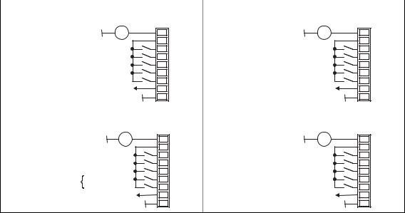
5 Before commissioning
5.3General notes on applications
_ _ _ _ _ _ _ _ _ _ _ _ _ _ _ _ _ _ _ _ _ _ _ _ _ _ _ _ _ _ _ _ _ _ _ _ _ _ _ _ _ _ _ _ _ _ _ _ _ _ _ _ _ _ _ _ _ _ _ _ _ _ _ _
5.3.1Select control mode
Different control modes can be selected for every application in C00007. By selecting the control mode you set the way the technology application should be controlled, e.g. via terminals or via a fieldbus.
C00007 |
|
|
|
Control mode |
|
|
|
|
|
|
|
|
Selection list (Lenze setting printed in bold) |
Info |
|
|
0 |
Wiring has changed |
This display appears if the FB interconnection has been |
|
|
|
changed in the preconfigured I/O interconnection. |
|
10 |
Terminals 0 |
The technology application is controlled via the digital |
|
12 |
Terminals 2 |
and analog input terminals of the controller. |
|
• For a short overview of the preconfigured terminal |
||
|
14 |
Terminals 11 |
|
|
assignment, see the following segment. |
||
|
16 |
Terminal 16 |
|
|
20 |
Keypad |
The technology application is controlled via the keypad. |
|
21 |
PC |
See reference manual. |
|
30 |
CAN |
|
|
40 |
MCI |
|
|
|
|
|
Pre-assignment of the digital terminals in the control modes "Terminals 0/2/11/16"
The four control modes "Terminals 0/2/11/16" only differ in the assignment of the digital terminals to the control inputs of the application:
Control mode "Terminals 0": |
Control mode "Terminals 2": |
External supply 24 V DC |
X4 |
External supply 24 V DC |
X4 |
|
= + |
= + |
|||
24E |
24E |
|||
|
24I |
|
24I |
|
Controller enable / reset error |
RFR |
Controller enable / reset error |
RFR |
|
Fixed setpoint 1/3 |
DI1 |
Fixed setpoint 1/3 |
DI1 |
|
Fixed setpoint 2/3 |
DI2 |
Fixed setpoint 2/3 |
DI2 |
|
DC brake |
DI3 |
Quickstop |
DI3 |
|
Change of direction of rotation |
DI4 |
Change of direction of rotation |
DI4 |
|
DriveReady |
DO1 |
DriveReady |
DO1 |
|
|
GIO |
|
GIO |
Control mode "Terminals 11": |
Control mode "Terminals 16": |
External supply 24 V DC |
X4 |
External supply 24 V DC |
X4 |
||
|
= + |
= + |
|||
|
24E |
24E |
|||
|
|
24I |
|
24I |
|
Controller enable / reset error |
RFR |
Controller enable / reset error |
RFR |
||
Change of direction of rotation |
DI1 |
Fixed setpoint 1/3 |
DI1 |
||
|
DC brake active |
DI2 |
Fixed setpoint 2/3 |
DI2 |
|
Motor potentiometer |
Speed higher |
DI3 |
Cw rotation quick stop |
DI3 |
|
Speed lower |
DI4 |
Ccw rotation quick stop |
DI4 |
||
|
|||||
|
DriveReady |
DO1 |
DriveReady |
DO1 |
|
|
|
GIO |
|
GIO |
|
22 |
Lenze · 8400 StateLine · Operating instructions · from Firmware V06.00 · DMS 1.2 EN · 12/2012 · TD05 |
5 Before commissioning
5.3General notes on applications
_ _ _ _ _ _ _ _ _ _ _ _ _ _ _ _ _ _ _ _ _ _ _ _ _ _ _ _ _ _ _ _ _ _ _ _ _ _ _ _ _ _ _ _ _ _ _ _ _ _ _ _ _ _ _ _ _ _ _ _ _ _ _ _
Comparison of the control modes "Terminals 0/2/11/16"
The following table shows which functions of the preset application "actuating drive speed" have been preconfigured in the prevailing control mode for a control via terminals (Lenze setting printed in bold):
Control mode "terminals"... |
Function of the application |
Info |
|
|
|||
0 |
2 |
11 |
16 |
"actuating drive speed" |
|
|
|
|
|
|
|
||||
DI1 |
DI1 |
- |
DI1 |
Overriding fixed setpoints |
Alternatively to the speed selection via the analog |
||
DI2 |
DI2 |
|
DI2 |
|
input, "fixed setpoints" (JOG values" can also be |
||
|
|
|
|
|
activated via the digital terminals. |
||
|
|
|
|
|
|
|
|
|
|
|
|
|
DI1 |
DI2 |
Speed selection |
|
|
|
|
|
LOW |
LOW |
Via analog input 1 |
|
|
|
|
|
|
|
(Terminal A1U) |
|
|
|
|
|
|
|
|
|
|
|
|
|
HIGH |
LOW |
Fixed setpoint 1 |
|
|
|
|
|
|
|
(C00039/1: 40 %) |
|
|
|
|
|
|
|
|
|
|
|
|
|
LOW |
HIGH |
Fixed setpoint 2 |
|
|
|
|
|
|
|
(C00039/2: 60 %) |
|
|
|
|
|
|
|
|
|
|
|
|
|
HIGH |
HIGH |
Fixed setpoint 3 |
|
|
|
|
|
|
|
(C00039/3: 80 %) |
DI3 |
- |
DI2 |
- |
Manual |
Manual DC-injection braking allows the drive to be |
||
|
|
|
|
DC-injection braking |
quickly braked to a standstill without the need to use |
||
|
|
|
|
|
an external brake resistor. |
||
- |
DI3 |
- |
- |
Quick stop |
The quick stop function decouples the motor control |
||
|
|
|
|
|
from the setpoint selection. The motor is braked to |
||
|
|
|
|
|
standstill with the adjustable ramp time (nact= 0). |
||
DI4 |
DI4 |
DI1 |
- |
Change of direction of |
|
|
|
|
|
|
|
rotation |
|
|
|
- |
- |
- |
DI3 |
Fail-safe |
DI3 |
DI4 |
Selection of direction of |
|
|
|
DI4 |
selection of direction of |
|
|
rotation |
|
|
|
|
rotation |
LOW |
LOW |
Quick stop |
|
|
|
|
|
|||
|
|
|
|
|
|
|
|
|
|
|
|
|
HIGH |
LOW |
Clockwise rotation |
|
|
|
|
|
|
|
|
|
|
|
|
|
LOW |
HIGH |
Counter-clockwise rotation |
|
|
|
|
|
|
|
|
|
|
|
|
|
HIGH |
HIGH |
No change |
- |
- |
DI3 |
- |
Motor potentiometer |
This motor potentiometer function replaces a |
||
|
|
DI4 |
|
|
hardware motor potentiometer and can be used as |
||
|
|
|
|
|
an alternative setpoint source which is controlled via |
||
|
|
|
|
|
two inputs. Motor potentiometer ( 65) |
||
|
|
|
|
|
DI3 |
DI4 |
Function |
|
|
|
|
|
LOW |
LOW |
No change |
|
|
|
|
|
|
|
|
|
|
|
|
|
HIGH |
LOW |
Increase speed |
|
|
|
|
|
|
|
|
|
|
|
|
|
LOW |
HIGH |
Decrease speed |
|
|
|
|
|
|
|
|
|
|
|
|
|
HIGH |
HIGH |
No change |
- |
- |
- |
- |
Process controller |
If required, the process controller can be |
||
|
|
|
|
|
implemented in the signal flow of the application via |
||
|
|
|
|
|
configuration parameters. Process controller |
||
|
|
|
|
|
( 68) |
|
|
Lenze · 8400 StateLine · Operating instructions · from Firmware V06.00 · DMS 1.2 EN · 12/2012 · TD05 |
23 |
Loading...