


 Loading...
Automation Systems
Controller-based
Automation
EtherCAT®_ _ _ _ _ _ _ _ _ _ _ _ _ _ _ _ _ _ _ _ _ _ _ _ _ _ _ _ _ _ _ _ _ |
Communication Manual |
EN |
Ä.O5ôä 13462095
L
Contents
_ _ _ _ _ _ _ _ _ _ _ _ _ _ _ _ _ _ _ _ _ _ _ _ _ _ _ _ _ _ _ _ _ _ _ _ _ _ _ _ _ _ _ _ _ _ _ _ _ _ _ _ _ _ _ _ _ _ _ _ _ _ _ _
1 |
About this documentation _ _ _ _ _ _ _ _ _ _ _ _ _ _ _ _ _ _ _ _ _ _ _ _ _ _ _ _ _ _ _ _ _ _ _ _ _ _ _ |
6 |
||||
1.1 |
Document history |
_ _ _ _ _ _ _ _ _ _ _ _ _ _ _ _ _ _ _ _ _ _ _ _ _ _ _ _ _ _ _ _ _ _ _ _ _ _ _ _ _ _ _ _ |
8 |
|||
1.2 |
Conventions used |
_ _ _ _ _ _ _ _ _ _ _ _ _ _ _ _ _ _ _ _ _ _ _ _ _ _ _ _ _ _ _ _ _ _ _ _ _ _ _ _ _ _ _ _ |
9 |
|||
1.3 |
Terminology used |
_ _ _ _ _ _ _ _ _ _ _ _ _ _ _ _ _ _ _ _ _ _ _ _ _ _ _ _ _ _ _ _ _ _ _ _ _ _ _ _ _ _ _ _ |
10 |
|||
1.4 |
Definition of the notes used _ _ _ _ _ _ _ _ _ _ _ _ _ _ _ _ _ _ _ _ _ _ _ _ _ _ _ _ _ _ _ _ _ _ _ _ _ _ |
12 |
||||
2 |
Safety instructions _ _ _ _ _ _ _ _ _ _ _ _ _ _ _ _ _ _ _ _ _ _ _ _ _ _ _ _ _ _ _ _ _ _ _ _ _ _ _ _ _ _ _ _ |
13 |
||||
3 |
Controller-based Automation: Central motion control |
_ _ _ _ _ _ _ _ _ _ _ _ _ _ _ _ _ _ _ _ _ _ _ _ |
14 |
|||
4 |
The Lenze automation system with EtherCAT _ _ _ _ _ _ _ _ _ _ _ _ _ _ _ _ _ _ _ _ _ _ _ _ _ _ _ _ _ |
17 |
||||
4.1 |
Brief description of EtherCAT _ _ _ _ _ _ _ _ _ _ _ _ _ _ _ _ _ _ _ _ _ _ _ _ _ _ _ _ _ _ _ _ _ _ _ _ _ _ |
17 |
||||
|
4.1.1 |
Structure of the EtherCAT bus system _ _ _ _ _ _ _ _ _ _ _ _ _ _ _ _ _ _ _ _ _ _ _ _ _ _ _ _ |
18 |
|||
|
4.1.2 |
Communication _ _ _ _ _ _ _ _ _ _ _ _ _ _ _ _ _ _ _ _ _ _ _ _ _ _ _ _ _ _ _ _ _ _ _ _ _ _ _ _ |
19 |
|||
|
|
4.1.2.1 |
The EtherCAT state machine _ _ _ _ _ _ _ _ _ _ _ _ _ _ _ _ _ _ _ _ _ _ _ _ _ _ _ |
20 |
||
|
|
4.1.2.2 |
Addressing of the slaves |
_ _ _ _ _ _ _ _ _ _ _ _ _ _ _ _ _ _ _ _ _ _ _ _ _ _ _ _ _ |
22 |
|
|
|
4.1.2.3 |
Working counter _ _ _ _ _ _ _ _ _ _ _ _ _ _ _ _ _ _ _ _ _ _ _ _ _ _ _ _ _ _ _ _ _ _ |
23 |
||
4.2 |
Required hardware components _ _ _ _ _ _ _ _ _ _ _ _ _ _ _ _ _ _ _ _ _ _ _ _ _ _ _ _ _ _ _ _ _ _ _ _ |
24 |
||||
|
4.2.1 |
Field devices _ _ _ _ _ _ _ _ _ _ _ _ _ _ _ _ _ _ _ _ _ _ _ _ _ _ _ _ _ _ _ _ _ _ _ _ _ _ _ _ _ _ |
24 |
|||
|
4.2.2 |
The Lenze Controller - the central component _ _ _ _ _ _ _ _ _ _ _ _ _ _ _ _ _ _ _ _ _ _ _ _ |
25 |
|||
|
4.2.3 |
EtherCAT product codes _ _ _ _ _ _ _ _ _ _ _ _ _ _ _ _ _ _ _ _ _ _ _ _ _ _ _ _ _ _ _ _ _ _ _ _ |
26 |
|||
|
4.2.4 |
The EtherCAT interface of the Lenze Controller |
_ _ _ _ _ _ _ _ _ _ _ _ _ _ _ _ _ _ _ _ _ _ _ |
28 |
||
4.3 |
Lenze Engineering tools _ _ _ _ _ _ _ _ _ _ _ _ _ _ _ _ _ _ _ _ _ _ _ _ _ _ _ _ _ _ _ _ _ _ _ _ _ _ _ _ _ |
29 |
||||
4.4 |
Interaction of the components _ _ _ _ _ _ _ _ _ _ _ _ _ _ _ _ _ _ _ _ _ _ _ _ _ _ _ _ _ _ _ _ _ _ _ _ _ |
30 |
||||
|
4.4.1 |
The state machine of the Lenze control technology _ _ _ _ _ _ _ _ _ _ _ _ _ _ _ _ _ _ _ _ _ |
30 |
|||
|
4.4.2 |
Communication between the Engineering PC and the field devices _ _ _ _ _ _ _ _ _ _ _ _ |
32 |
|||
|
|
4.4.2.1 |
EtherCAT bus not in operation _ _ _ _ _ _ _ _ _ _ _ _ _ _ _ _ _ _ _ _ _ _ _ _ _ _ |
32 |
||
|
|
4.4.2.2 |
EtherCAT bus in operation (gateway function) _ _ _ _ _ _ _ _ _ _ _ _ _ _ _ _ _ |
33 |
||
5 |
Technical data _ _ _ _ _ _ _ _ _ _ _ _ _ _ _ _ _ _ _ _ _ _ _ _ _ _ _ _ _ _ _ _ _ _ _ _ _ _ _ _ _ _ _ _ _ _ |
34 |
||||
5.1 |
General data _ _ _ _ _ _ _ _ _ _ _ _ _ _ _ _ _ _ _ _ _ _ _ _ _ _ _ _ _ _ _ _ _ _ _ _ _ _ _ _ _ _ _ _ _ _ _ |
34 |
||||
5.2 |
EtherCAT interface of the Lenze Controller |
_ _ _ _ _ _ _ _ _ _ _ _ _ _ _ _ _ _ _ _ _ _ _ _ _ _ _ _ _ _ |
34 |
|||
5.3 |
Communication times and drive-specific data _ _ _ _ _ _ _ _ _ _ _ _ _ _ _ _ _ _ _ _ _ _ _ _ _ _ _ _ _ |
35 |
||||
6 |
Synchronisation with "Distributed clocks" (DC) _ _ _ _ _ _ _ _ _ _ _ _ _ _ _ _ _ _ _ _ _ _ _ _ _ _ _ _ |
36 |
||||
6.1 |
Synchronous communication _ _ _ _ _ _ _ _ _ _ _ _ _ _ _ _ _ _ _ _ _ _ _ _ _ _ _ _ _ _ _ _ _ _ _ _ _ _ |
37 |
||||
6.2 |
Test of DC synchronicity _ _ _ _ _ _ _ _ _ _ _ _ _ _ _ _ _ _ _ _ _ _ _ _ _ _ _ _ _ _ _ _ _ _ _ _ _ _ _ _ _ |
38 |
||||
2 |
Lenze · Controller-based Automation · EtherCAT® Communication Manual · DMS 6.4 EN · 04/2014 · TD17 |
Contents
_ _ _ _ _ _ _ _ _ _ _ _ _ _ _ _ _ _ _ _ _ _ _ _ _ _ _ _ _ _ _ _ _ _ _ _ _ _ _ _ _ _ _ _ _ _ _ _ _ _ _ _ _ _ _ _ _ _ _ _ _ _ _ _
7 |
Commissioning of the system _ _ _ _ _ _ _ _ _ _ _ _ _ _ _ _ _ _ _ _ _ _ _ _ _ _ _ _ _ _ _ _ _ _ _ _ _ |
39 |
||||||||
7.1 |
Sample projects (Application Samples) _ _ _ _ _ _ _ _ _ _ _ _ _ _ _ _ _ _ _ _ _ _ _ _ _ _ _ _ _ _ _ _ _ |
39 |
||||||||
7.2 |
Overview of the commissioning steps |
_ _ _ _ _ _ _ _ _ _ _ _ _ _ _ _ _ _ _ _ _ _ _ _ _ _ _ _ _ _ _ _ _ |
40 |
|||||||
7.3 |
Detailed description of the commissioning steps |
_ _ _ _ _ _ _ _ _ _ _ _ _ _ _ _ _ _ _ _ _ _ _ _ _ _ _ |
42 |
|||||||
|
7.3.1 |
Planning the bus topology _ _ _ _ _ _ _ _ _ _ _ _ _ _ _ _ _ _ _ _ _ _ _ _ _ _ _ _ _ _ _ _ _ _ _ |
42 |
|||||||
|
7.3.2 |
Installing field devices _ _ _ _ _ _ _ _ _ _ _ _ _ _ _ _ _ _ _ _ _ _ _ _ _ _ _ _ _ _ _ _ _ _ _ _ _ |
43 |
|||||||
|
7.3.3 |
Create a project folder _ _ _ _ _ _ _ _ _ _ _ _ _ _ _ _ _ _ _ _ _ _ _ _ _ _ _ _ _ _ _ _ _ _ _ _ _ |
43 |
|||||||
|
7.3.4 |
Commissioning the i700 servo inverter _ _ _ _ _ _ _ _ _ _ _ _ _ _ _ _ _ _ _ _ _ _ _ _ _ _ _ _ |
44 |
|||||||
|
|
7.3.4.1 |
i700 parameter management in the Controller-based Automation |
|
||||||
|
|
|
system _ _ _ _ _ _ _ _ _ _ _ _ _ _ _ _ _ _ _ _ _ _ _ _ _ _ _ _ _ _ _ _ _ _ _ _ _ _ _ |
45 |
||||||
|
|
7.3.4.2 |
i700 parameter management in »EASY Starter« |
_ _ _ _ _ _ _ _ _ _ _ _ _ _ _ _ |
49 |
|||||
|
|
7.3.4.3 |
Exchanging i700 parameter sets between »PLC Designer« and |
|
||||||
|
|
|
»EASY Starter« _ _ _ _ _ _ _ _ _ _ _ _ _ _ _ _ _ _ _ _ _ _ _ _ _ _ _ _ _ _ _ _ _ _ _ |
51 |
||||||
|
|
7.3.4.4 |
Overview of the commissioning steps |
_ _ _ _ _ _ _ _ _ _ _ _ _ _ _ _ _ _ _ _ _ _ |
52 |
|||||
|
|
7.3.4.5 |
Checking the wiring _ _ _ _ _ _ _ _ _ _ _ _ _ _ _ _ _ _ _ _ _ _ _ _ _ _ _ _ _ _ _ _ |
53 |
||||||
|
|
7.3.4.6 |
Entering motor and controller settings |
_ _ _ _ _ _ _ _ _ _ _ _ _ _ _ _ _ _ _ _ _ |
54 |
|||||
|
|
7.3.4.7 |
Setting the feedback system for servo control _ _ _ _ _ _ _ _ _ _ _ _ _ _ _ _ _ _ |
57 |
||||||
|
|
7.3.4.8 |
Integrating the L_SMC_AxisBasicControl function block _ _ _ _ _ _ _ _ _ _ _ _ |
59 |
||||||
|
|
7.3.4.9 |
Executing manual control _ _ _ _ _ _ _ _ _ _ _ _ _ _ _ _ _ _ _ _ _ _ _ _ _ _ _ _ _ |
65 |
||||||
|
|
7.3.4.10 |
Optimising control |
_ _ _ _ _ _ _ _ _ _ _ _ _ _ _ _ _ _ _ _ _ _ _ _ _ _ _ _ _ _ _ _ |
67 |
|||||
|
7.3.5 |
Commissioning other Lenze field devices |
_ _ _ _ _ _ _ _ _ _ _ _ _ _ _ _ _ _ _ _ _ _ _ _ _ _ |
70 |
||||||
|
7.3.6 |
Creating a PLC program with a target system (Logic/Motion) _ _ _ _ _ _ _ _ _ _ _ _ _ _ _ _ |
71 |
|||||||
|
7.3.7 |
Configuring the communication parameters |
_ _ _ _ _ _ _ _ _ _ _ _ _ _ _ _ _ _ _ _ _ _ _ _ |
73 |
||||||
|
7.3.8 |
Determining the physical EtherCAT configuration (fieldbus scan) _ _ _ _ _ _ _ _ _ _ _ _ _ |
75 |
|||||||
|
7.3.9 |
Importing missing devices / device description files _ _ _ _ _ _ _ _ _ _ _ _ _ _ _ _ _ _ _ _ _ |
78 |
|||||||
|
7.3.10 |
Creating a control configuration (adding field devices) _ _ _ _ _ _ _ _ _ _ _ _ _ _ _ _ _ _ _ |
79 |
|||||||
|
7.3.11 |
Creating a task _ _ _ _ _ _ _ _ _ _ _ _ _ _ _ _ _ _ _ _ _ _ _ _ _ _ _ _ _ _ _ _ _ _ _ _ _ _ _ _ _ |
82 |
|||||||
|
7.3.12 |
Setting a DC synchronisation |
_ _ _ _ _ _ _ _ _ _ _ _ _ _ _ _ _ _ _ _ _ _ _ _ _ _ _ _ _ _ _ _ _ |
87 |
||||||
|
7.3.13 |
Setting SoftMotion parameters _ _ _ _ _ _ _ _ _ _ _ _ _ _ _ _ _ _ _ _ _ _ _ _ _ _ _ _ _ _ _ _ |
92 |
|||||||
|
7.3.14 |
Processing EtherCAT I/O mapping _ _ _ _ _ _ _ _ _ _ _ _ _ _ _ _ _ _ _ _ _ _ _ _ _ _ _ _ _ _ |
95 |
|||||||
|
|
7.3.14.1 |
Entering the settings for PDO mapping |
_ _ _ _ _ _ _ _ _ _ _ _ _ _ _ _ _ _ _ _ _ |
96 |
|||||
|
|
7.3.14.2 |
Configuring individual PDO mapping |
_ _ _ _ _ _ _ _ _ _ _ _ _ _ _ _ _ _ _ _ _ _ |
97 |
|||||
|
|
7.3.14.3 |
PDO mapping for logic devices _ _ _ _ _ _ _ _ _ _ _ _ _ _ _ _ _ _ _ _ _ _ _ _ _ _ |
100 |
||||||
|
|
7.3.14.4 |
Using PDO mapping settings from »Engineer« |
_ _ _ _ _ _ _ _ _ _ _ _ _ _ _ _ _ |
101 |
|||||
|
7.3.15 |
Compiling the PLC program code _ _ _ _ _ _ _ _ _ _ _ _ _ _ _ _ _ _ _ _ _ _ _ _ _ _ _ _ _ _ _ |
103 |
|||||||
|
7.3.16 |
Logging in on the controller with the »PLC Designer« _ _ _ _ _ _ _ _ _ _ _ _ _ _ _ _ _ _ _ _ |
103 |
|||||||
|
7.3.17 |
Starting the PLC program |
_ _ _ _ _ _ _ _ _ _ _ _ _ _ _ _ _ _ _ _ _ _ _ _ _ _ _ _ _ _ _ _ _ _ _ |
103 |
||||||
|
7.3.18 |
Start parameters of the Servo Drives 9400 HighLine CiA 402 _ _ _ _ _ _ _ _ _ _ _ _ _ _ _ _ |
103 |
|||||||
|
7.3.19 |
Optimising the task utilisation _ _ _ _ _ _ _ _ _ _ _ _ _ _ _ _ _ _ _ _ _ _ _ _ _ _ _ _ _ _ _ _ |
104 |
|||||||
7.4 |
State diagram for commissioning |
_ _ _ _ _ _ _ _ _ _ _ _ _ _ _ _ _ _ _ _ _ _ _ _ _ _ _ _ _ _ _ _ _ _ _ |
105 |
|||||||
8 |
Mixed operation - EtherCAT with other bus systems |
_ _ _ _ _ _ _ _ _ _ _ _ _ _ _ _ _ _ _ _ _ _ _ _ _ |
106 |
|||||||
8.1 |
CANopen and EtherCAT _ _ _ _ _ _ _ _ _ _ _ _ _ _ _ _ _ _ _ _ _ _ _ _ _ _ _ _ _ _ _ _ _ _ _ _ _ _ _ _ _ |
107 |
||||||||
8.2 |
PROFIBUS as the logic bus and EtherCAT as a logic bus or motion bus _ _ _ _ _ _ _ _ _ _ _ _ _ _ _ _ |
108 |
||||||||
8.3 |
EtherCAT and PROFINET _ _ _ _ _ _ _ _ _ _ _ _ _ _ _ _ _ _ _ _ _ _ _ _ _ _ _ _ _ _ _ _ _ _ _ _ _ _ _ _ _ |
109 |
||||||||
Lenze · Controller-based Automation · EtherCAT® Communication Manual · DMS 6.4 EN · 04/2014 · TD17 |
3 |
Contents
_ _ _ _ _ _ _ _ _ _ _ _ _ _ _ _ _ _ _ _ _ _ _ _ _ _ _ _ _ _ _ _ _ _ _ _ _ _ _ _ _ _ _ _ _ _ _ _ _ _ _ _ _ _ _ _ _ _ _ _ _ _ _ _
9 |
Function library L_IODrvEtherCAT.lib |
_ _ _ _ _ _ _ _ _ _ _ _ _ _ _ _ _ _ _ _ _ _ _ _ _ _ _ _ _ _ _ _ _ |
110 |
|||||
9.1 |
Overview of functions and function blocks |
_ _ _ _ _ _ _ _ _ _ _ _ _ _ _ _ _ _ _ _ _ _ _ _ _ _ _ _ _ _ |
114 |
|||||
9.2 |
CoE Interface _ _ _ _ _ _ _ _ _ _ _ _ _ _ _ _ _ _ _ _ _ _ _ _ _ _ _ _ _ _ _ _ _ _ _ _ _ _ _ _ _ _ _ _ _ _ _ |
115 |
||||||
|
9.2.1 |
Reading and writing parameters |
_ _ _ _ _ _ _ _ _ _ _ _ _ _ _ _ _ _ _ _ _ _ _ _ _ _ _ _ _ _ _ |
115 |
||||
|
|
9.2.1.1 |
Reading parameters (SDO upload) _ _ _ _ _ _ _ _ _ _ _ _ _ _ _ _ _ _ _ _ _ _ _ _ |
116 |
||||
|
|
9.2.1.2 |
Writing parameters (SDO download) _ _ _ _ _ _ _ _ _ _ _ _ _ _ _ _ _ _ _ _ _ _ |
120 |
||||
|
9.2.2 |
L_ETC_CoE_SdoRead (FB) _ _ _ _ _ _ _ _ _ _ _ _ _ _ _ _ _ _ _ _ _ _ _ _ _ _ _ _ _ _ _ _ _ _ _ |
125 |
|||||
|
9.2.3 |
L_ETC_CoE_SdoRead4 (FB) |
_ _ _ _ _ _ _ _ _ _ _ _ _ _ _ _ _ _ _ _ _ _ _ _ _ _ _ _ _ _ _ _ _ _ |
127 |
||||
|
9.2.4 |
L_ETC_CoE_SdoReadEx (FB) _ _ _ _ _ _ _ _ _ _ _ _ _ _ _ _ _ _ _ _ _ _ _ _ _ _ _ _ _ _ _ _ _ _ |
129 |
|||||
|
9.2.5 |
L_ETC_CoE_SdoWrite (FB) _ _ _ _ _ _ _ _ _ _ _ _ _ _ _ _ _ _ _ _ _ _ _ _ _ _ _ _ _ _ _ _ _ _ _ |
131 |
|||||
|
9.2.6 |
L_ETC_CoE_SdoWrite4 (FB) |
_ _ _ _ _ _ _ _ _ _ _ _ _ _ _ _ _ _ _ _ _ _ _ _ _ _ _ _ _ _ _ _ _ _ |
133 |
||||
|
9.2.7 |
L_ETC_CoE_SdoWriteEx (FB) |
_ _ _ _ _ _ _ _ _ _ _ _ _ _ _ _ _ _ _ _ _ _ _ _ _ _ _ _ _ _ _ _ _ |
135 |
||||
9.3 |
Device Interface |
_ _ _ _ _ _ _ _ _ _ _ _ _ _ _ _ _ _ _ _ _ _ _ _ _ _ _ _ _ _ _ _ _ _ _ _ _ _ _ _ _ _ _ _ _ |
137 |
|||||
|
9.3.1 |
ETCSlave (FB) _ _ _ _ _ _ _ _ _ _ _ _ _ _ _ _ _ _ _ _ _ _ _ _ _ _ _ _ _ _ _ _ _ _ _ _ _ _ _ _ _ _ |
137 |
|||||
|
9.3.2 |
L_ETC_GetSlave (FUN) _ _ _ _ _ _ _ _ _ _ _ _ _ _ _ _ _ _ _ _ _ _ _ _ _ _ _ _ _ _ _ _ _ _ _ _ _ |
138 |
|||||
|
9.3.3 |
L_ETC_IoControl (FUN) |
_ _ _ _ _ _ _ _ _ _ _ _ _ _ _ _ _ _ _ _ _ _ _ _ _ _ _ _ _ _ _ _ _ _ _ _ |
139 |
||||
|
9.3.4 |
L_IODrvEtherCAT (FB) |
_ _ _ _ _ _ _ _ _ _ _ _ _ _ _ _ _ _ _ _ _ _ _ _ _ _ _ _ _ _ _ _ _ _ _ _ _ |
140 |
||||
9.4 |
Diagnostic Interface _ _ _ _ _ _ _ _ _ _ _ _ _ _ _ _ _ _ _ _ _ _ _ _ _ _ _ _ _ _ _ _ _ _ _ _ _ _ _ _ _ _ _ |
141 |
||||||
|
9.4.1 |
L_ETC_GetEmergency (FB) _ _ _ _ _ _ _ _ _ _ _ _ _ _ _ _ _ _ _ _ _ _ _ _ _ _ _ _ _ _ _ _ _ _ _ |
141 |
|||||
|
9.4.2 |
L_ETC_GetErrorString (FUN) _ _ _ _ _ _ _ _ _ _ _ _ _ _ _ _ _ _ _ _ _ _ _ _ _ _ _ _ _ _ _ _ _ _ |
143 |
|||||
|
9.4.3 |
L_ETC_GetMasterDiagnostic (FB) _ _ _ _ _ _ _ _ _ _ _ _ _ _ _ _ _ _ _ _ _ _ _ _ _ _ _ _ _ _ _ |
144 |
|||||
|
9.4.4 |
L_ETC_ReadErrCnt (FB) |
_ _ _ _ _ _ _ _ _ _ _ _ _ _ _ _ _ _ _ _ _ _ _ _ _ _ _ _ _ _ _ _ _ _ _ _ |
145 |
||||
|
9.4.5 |
L_ETC_ResetErrCnt (FB) _ _ _ _ _ _ _ _ _ _ _ _ _ _ _ _ _ _ _ _ _ _ _ _ _ _ _ _ _ _ _ _ _ _ _ _ |
146 |
|||||
9.5 |
FoE interface _ _ _ _ _ _ _ _ _ _ _ _ _ _ _ _ _ _ _ _ _ _ _ _ _ _ _ _ _ _ _ _ _ _ _ _ _ _ _ _ _ _ _ _ _ _ _ |
147 |
||||||
|
9.5.1 |
L_ETC_FoE_Read (FB) |
|
_ _ _ _ _ _ _ _ _ _ _ _ _ _ _ _ _ _ _ _ _ _ _ _ _ _ _ _ _ _ _ _ _ _ _ _ _ |
147 |
|||
|
9.5.2 |
L_ETC_FoE_Write (FB) |
_ _ _ _ _ _ _ _ _ _ _ _ _ _ _ _ _ _ _ _ _ _ _ _ _ _ _ _ _ _ _ _ _ _ _ _ _ |
149 |
||||
9.6 |
State Machine Interface _ _ _ _ _ _ _ _ _ _ _ _ _ _ _ _ _ _ _ _ _ _ _ _ _ _ _ _ _ _ _ _ _ _ _ _ _ _ _ _ _ |
151 |
||||||
|
9.6.1 |
L_ETC_GetMasterState (FB) _ _ _ _ _ _ _ _ _ _ _ _ _ _ _ _ _ _ _ _ _ _ _ _ _ _ _ _ _ _ _ _ _ _ |
151 |
|||||
|
9.6.2 |
L_ETC_GetSlaveState (FB) _ _ _ _ _ _ _ _ _ _ _ _ _ _ _ _ _ _ _ _ _ _ _ _ _ _ _ _ _ _ _ _ _ _ _ |
152 |
|||||
|
9.6.3 |
L_ETC_SetMasterState (FB) |
_ _ _ _ _ _ _ _ _ _ _ _ _ _ _ _ _ _ _ _ _ _ _ _ _ _ _ _ _ _ _ _ _ _ |
153 |
||||
|
9.6.4 |
L_ETC_SetSlaveState (FB) _ _ _ _ _ _ _ _ _ _ _ _ _ _ _ _ _ _ _ _ _ _ _ _ _ _ _ _ _ _ _ _ _ _ _ |
154 |
|||||
9.7 |
Data types _ _ _ _ _ _ _ _ _ _ _ _ _ _ _ _ _ _ _ _ _ _ _ _ _ _ _ _ _ _ _ _ _ _ _ _ _ _ _ _ _ _ _ _ _ _ _ _ |
155 |
||||||
|
9.7.1 |
L_ETC_COE_EMERGENCY _ _ _ _ _ _ _ _ _ _ _ _ _ _ _ _ _ _ _ _ _ _ _ _ _ _ _ _ _ _ _ _ _ _ _ |
155 |
|||||
|
9.7.2 |
L_ETC_COE_EMERGENCY_BUFFER_DATA _ _ _ _ _ _ _ _ _ _ _ _ _ _ _ _ _ _ _ _ _ _ _ _ _ _ |
155 |
|||||
|
9.7.3 |
L_ETC_COE_FLAGS _ _ _ _ _ _ _ _ _ _ _ _ _ _ _ _ _ _ _ _ _ _ _ _ _ _ _ _ _ _ _ _ _ _ _ _ _ _ _ |
155 |
|||||
|
9.7.4 |
L_ETC_DIAGNOSTIC |
_ _ _ _ _ _ _ _ _ _ _ _ _ _ _ _ _ _ _ _ _ _ _ _ _ _ _ _ _ _ _ _ _ _ _ _ _ _ |
156 |
||||
|
9.7.5 |
L_ETC_EVTPARAM_PARAMETERTRANSFER _ _ _ _ _ _ _ _ _ _ _ _ _ _ _ _ _ _ _ _ _ _ _ _ _ _ |
156 |
|||||
|
9.7.6 |
L_ETC_ERRORCODE |
_ _ _ _ _ _ _ _ _ _ _ _ _ _ _ _ _ _ _ _ _ _ _ _ _ _ _ _ _ _ _ _ _ _ _ _ _ _ |
157 |
||||
|
9.7.7 |
L_ETC_IOCTLOPARMS |
_ _ _ _ _ _ _ _ _ _ _ _ _ _ _ _ _ _ _ _ _ _ _ _ _ _ _ _ _ _ _ _ _ _ _ _ _ |
157 |
||||
|
9.7.8 |
L_ETC_LANGUAGE _ _ _ _ _ _ _ _ _ _ _ _ _ _ _ _ _ _ _ _ _ _ _ _ _ _ _ _ _ _ _ _ _ _ _ _ _ _ _ |
157 |
|||||
|
9.7.9 |
L_ETC_SLAVE_PORTS |
|
_ _ _ _ _ _ _ _ _ _ _ _ _ _ _ _ _ _ _ _ _ _ _ _ _ _ _ _ _ _ _ _ _ _ _ _ _ |
157 |
|||
|
9.7.10 |
L_ETC_PARAMETERTRANSFERSERVICE_CODE _ _ _ _ _ _ _ _ _ _ _ _ _ _ _ _ _ _ _ _ _ _ _ _ |
158 |
|||||
|
9.7.11 |
L_ETC_STATE (EtherCAT status) _ _ _ _ _ _ _ _ _ _ _ _ _ _ _ _ _ _ _ _ _ _ _ _ _ _ _ _ _ _ _ _ |
158 |
|||||
4 |
Lenze · Controller-based Automation · EtherCAT® Communication Manual · DMS 6.4 EN · 04/2014 · TD17 |
Contents
_ _ _ _ _ _ _ _ _ _ _ _ _ _ _ _ _ _ _ _ _ _ _ _ _ _ _ _ _ _ _ _ _ _ _ _ _ _ _ _ _ _ _ _ _ _ _ _ _ _ _ _ _ _ _ _ _ _ _ _ _ _ _ _
10 |
Restarting the EtherCAT fieldbus _ _ _ _ _ _ _ _ _ _ _ _ _ _ _ _ _ _ _ _ _ _ _ _ _ _ _ _ _ _ _ _ _ _ _ _ |
159 |
|||||
11 |
Defining the cycle time of the PLC project |
_ _ _ _ _ _ _ _ _ _ _ _ _ _ _ _ _ _ _ _ _ _ _ _ _ _ _ _ _ _ _ |
160 |
||||
11.1 |
Determining the task utilisation of the application _ _ _ _ _ _ _ _ _ _ _ _ _ _ _ _ _ _ _ _ _ _ _ _ _ _ |
160 |
|||||
11.2 |
Optimising the system |
_ _ _ _ _ _ _ _ _ _ _ _ _ _ _ _ _ _ _ _ _ _ _ _ _ _ _ _ _ _ _ _ _ _ _ _ _ _ _ _ _ |
162 |
||||
12 |
Diagnostics _ _ _ _ _ _ _ _ _ _ _ _ _ _ _ _ _ _ _ _ _ _ _ _ _ _ _ _ _ _ _ _ _ _ _ _ _ _ _ _ _ _ _ _ _ _ _ _ |
163 |
|||||
12.1 |
Diagnostics with the »PLC Designer« _ _ _ _ _ _ _ _ _ _ _ _ _ _ _ _ _ _ _ _ _ _ _ _ _ _ _ _ _ _ _ _ _ _ |
163 |
|||||
|
12.1.1 |
Representation in the online mode _ _ _ _ _ _ _ _ _ _ _ _ _ _ _ _ _ _ _ _ _ _ _ _ _ _ _ _ _ _ |
163 |
||||
|
12.1.2 |
Diagnostic tabs of the EtherCAT master _ _ _ _ _ _ _ _ _ _ _ _ _ _ _ _ _ _ _ _ _ _ _ _ _ _ _ |
164 |
||||
|
12.1.3 |
Display window for EtherCAT logbook messages _ _ _ _ _ _ _ _ _ _ _ _ _ _ _ _ _ _ _ _ _ _ |
165 |
||||
|
12.1.4 |
Visualisation of the function block L_ETC_GetMasterDiagnostic _ _ _ _ _ _ _ _ _ _ _ _ _ _ |
166 |
||||
12.2 |
Diagnostic codes in the »WebConfig« |
_ _ _ _ _ _ _ _ _ _ _ _ _ _ _ _ _ _ _ _ _ _ _ _ _ _ _ _ _ _ _ _ _ |
169 |
||||
12.3 |
Logbook of the Lenze Controller in the »WebConfig« _ _ _ _ _ _ _ _ _ _ _ _ _ _ _ _ _ _ _ _ _ _ _ _ _ |
170 |
|||||
12.4 |
Error counters of the EtherCAT slaves |
_ _ _ _ _ _ _ _ _ _ _ _ _ _ _ _ _ _ _ _ _ _ _ _ _ _ _ _ _ _ _ _ _ |
172 |
||||
|
12.4.1 |
Error types "Errors" and "Forwarded Errors" |
_ _ _ _ _ _ _ _ _ _ _ _ _ _ _ _ _ _ _ _ _ _ _ _ _ |
172 |
|||
|
12.4.2 |
Error counter reset from the application _ _ _ _ _ _ _ _ _ _ _ _ _ _ _ _ _ _ _ _ _ _ _ _ _ _ _ |
173 |
||||
12.5 |
Error scenarios _ _ _ _ _ _ _ _ _ _ _ _ _ _ _ _ _ _ _ _ _ _ _ _ _ _ _ _ _ _ _ _ _ _ _ _ _ _ _ _ _ _ _ _ _ _ |
174 |
|||||
|
12.5.1 |
The EtherCAT bus does not assume the "Pre-Operational" state. _ _ _ _ _ _ _ _ _ _ _ _ _ _ |
175 |
||||
|
12.5.2 |
The EtherCAT bus does not assume the "Operational" state _ _ _ _ _ _ _ _ _ _ _ _ _ _ _ _ |
176 |
||||
|
12.5.3 |
Messages: WKC Error / Not all slaves "Operational" / SyncManager Watchdog _ _ _ _ _ _ |
177 |
||||
|
12.5.4 |
Error during process data transfer |
_ _ _ _ _ _ _ _ _ _ _ _ _ _ _ _ _ _ _ _ _ _ _ _ _ _ _ _ _ _ |
178 |
|||
|
12.5.5 |
Message: EtherCAT cable not connected / connected _ _ _ _ _ _ _ _ _ _ _ _ _ _ _ _ _ _ _ _ |
180 |
||||
|
12.5.6 Message: Frame Response Error _ _ _ _ _ _ _ _ _ _ _ _ _ _ _ _ _ _ _ _ _ _ _ _ _ _ _ _ _ _ _ _ |
180 |
|||||
|
12.5.7 |
Shafts make clicking noises _ _ _ _ _ _ _ _ _ _ _ _ _ _ _ _ _ _ _ _ _ _ _ _ _ _ _ _ _ _ _ _ _ _ |
181 |
||||
|
12.5.8 |
Shafts do not rotate _ _ _ _ _ _ _ _ _ _ _ _ _ _ _ _ _ _ _ _ _ _ _ _ _ _ _ _ _ _ _ _ _ _ _ _ _ _ |
182 |
||||
12.6 |
System error messages |
_ _ _ _ _ _ _ _ _ _ _ _ _ _ _ _ _ _ _ _ _ _ _ _ _ _ _ _ _ _ _ _ _ _ _ _ _ _ _ _ _ |
183 |
||||
|
12.6.1 |
General error codes (L_ETC_ERRORCODE) |
_ _ _ _ _ _ _ _ _ _ _ _ _ _ _ _ _ _ _ _ _ _ _ _ _ _ |
183 |
|||
|
12.6.2 Lenze Controller logbook messages _ _ _ _ _ _ _ _ _ _ _ _ _ _ _ _ _ _ _ _ _ _ _ _ _ _ _ _ _ _ |
190 |
|||||
|
12.6.3 |
SDO abort codes _ _ _ _ _ _ _ _ _ _ _ _ _ _ _ _ _ _ _ _ _ _ _ _ _ _ _ _ _ _ _ _ _ _ _ _ _ _ _ _ |
195 |
||||
13 |
Parameter reference _ _ _ _ _ _ _ _ _ _ _ _ _ _ _ _ _ _ _ _ _ _ _ _ _ _ _ _ _ _ _ _ _ _ _ _ _ _ _ _ _ _ _ |
196 |
|||||
|
Index _ _ _ _ _ _ _ _ _ _ _ _ _ _ _ _ _ _ _ _ _ _ _ _ _ _ _ _ _ _ _ _ _ _ _ _ _ _ _ _ _ _ _ _ _ _ _ _ _ _ _ |
201 |
|||||
|
Your opinion is important to us _ _ _ _ _ _ _ _ _ _ _ _ _ _ _ _ _ _ _ _ _ _ _ _ _ _ _ _ _ _ _ _ _ _ _ _ _ |
204 |
|||||
Lenze · Controller-based Automation · EtherCAT® Communication Manual · DMS 6.4 EN · 04/2014 · TD17 |
5 |
1 About this documentation
_ _ _ _ _ _ _ _ _ _ _ _ _ _ _ _ _ _ _ _ _ _ _ _ _ _ _ _ _ _ _ _ _ _ _ _ _ _ _ _ _ _ _ _ _ _ _ _ _ _ _ _ _ _ _ _ _ _ _ _ _ _ _ _
1 |
About this documentation |
This documentation ...
•contains detailed information about the commissioning, configuration, and diagnostics of the EtherCAT® bus system as part of the Lenze automation system "Controller-based Automation".
•is part of the "Controller-based Automation" manual collection. It consists of the following sets of documentation:
Documentation type |
Subject |
System manuals |
System overview/sample topologies |
|
• Controller-based Automation |
|
• Visualising |
Communication manuals |
Bus systems |
Online helps |
• Controller-based Automation EtherCAT® |
|
• Controller-based Automation CANopen® |
|
• Controller-based Automation PROFIBUS® |
|
• Controller-based Automation PROFINET® |
Reference manuals |
Lenze Controller: |
Online helps |
• Controller 3200 C |
|
• Controller c300 |
|
• Controller p300 |
|
• Controller p500 |
Software manuals |
Lenze Engineering Tools: |
Online helps |
• »PLC Designer«: Programming |
|
• »Engineer«: Inverter configuration |
|
• »VisiWinNET® Smart«: Visualisation |
|
• »Backup & Restore«: Back up/restore data |
|
|
6 |
Lenze · Controller-based Automation · EtherCAT® Communication Manual · DMS 6.4 EN · 04/2014 · TD17 |

1 About this documentation
_ _ _ _ _ _ _ _ _ _ _ _ _ _ _ _ _ _ _ _ _ _ _ _ _ _ _ _ _ _ _ _ _ _ _ _ _ _ _ _ _ _ _ _ _ _ _ _ _ _ _ _ _ _ _ _ _ _ _ _ _ _ _ _
More technical documentation for Lenze components
Further information on Lenze products which can be used in conjunction with Controller-based Automation can be found in the following sets of documentation:
Mounting & wiring
Mounting instructions
•Controller
•Communication cards (MC-xxx)
•I/O system 1000 (EPM-Sxxx)
•Inverter, Servo Drives
•Communication modules
Operating instructions
•Controller
•Servo system ECS (ECSxE, ECSxM)
Sample applications/Using application templates
Online help/software manuals
•Application Sample i700
•Application Samples
•ApplicationTemplate
Parameter setting, configuration, commissioning
Online help/reference manuals
•L-force Controller
•Inverter, Servo Drives
•I/O system 1000 (EPM-Sxxx)
Online help/communication manuals
•Bus systems
•Communication modules
Operating instructions
•Servo system ECS (ECSxE, ECSxM)
Symbols:
Printed documentation
Online help in the Lenze Engineering Tool (also available as PDF file at www.lenze.com.)
Tip!
Current documentation and software updates with regard to Lenze products can be found in the download area at:
www.lenze.com
Target group
This documentation is intended for persons who plan, install, commission and maintain the networking of devices as part of the Lenze automation system "Controller-based Automation".
Information on validity
The information provided in this documentation is valid for the Lenze automation system "Controller-based Automation" from version 3.
Screenshots/application examples
All screenshots in this documentation are application examples. Depending on the firmware version of the field devices and the software version of the Engineering tools installed (e.g. »PLC Designer« ), screenshots in this documentation may differ from the representation on the screen.
Lenze · Controller-based Automation · EtherCAT® Communication Manual · DMS 6.4 EN · 04/2014 · TD17 |
7 |
1 About this documentation
1.1Document history
_ _ _ _ _ _ _ _ _ _ _ _ _ _ _ _ _ _ _ _ _ _ _ _ _ _ _ _ _ _ _ _ _ _ _ _ _ _ _ _ _ _ _ _ _ _ _ _ _ _ _ _ _ _ _ _ _ _ _ _ _ _ _ _
1.1Document history
Version |
|
|
Description |
|
1.0 |
|
09/2008 |
TD17 |
First edition |
2.0 |
|
05/2009 |
TD17 |
General revision |
3.0 |
|
10/2009 |
TD17 |
General revision |
4.0 |
|
10/2010 |
TD17 |
Commissioning and configuration with the Lenze »PLC Designer« V3.x |
4.1 |
|
03/2011 |
TD17 |
• Special features for the ECS servo system added. |
|
|
|
|
• References to Lenze sample projects for EtherCAT logic field devices (device |
|
|
|
|
application + PLC program) added. |
|
|
|
|
Commissioning of the system ( 39) |
4.2 |
|
12/2011 |
TD17 |
• Revision on the Lenze automation system"Controller-based Automation", |
|
|
|
|
Release 3.2 |
|
|
|
|
• Chapter Function library L_IODrvEtherCAT.lib ( 110) updated. |
5.0 |
|
08/2012 |
TD17 |
• Revision on the Lenze automation system"Controller-based Automation", |
|
|
|
|
Release 3.3 |
|
|
|
|
• Information on the Servo-Inverter i700 added. |
|
|
|
|
• Information on the ECS servo system and »GDC« removed. |
6.0 |
|
11/2012 |
TD17 |
• General corrections |
|
|
|
|
• New layout |
6.1 |
|
12/2012 |
TD17 |
New function block L_ETC_GetEmergency (FB) ( 141) in the Lenze automation |
|
|
|
|
system "Controller-based Automation", Release 3.4 |
6.3 |
|
11/2013 |
TD17 |
Revision on the Lenze automation system"Controller-based Automation", |
|
|
|
|
release 3.6 |
6.4 |
|
04/2014 |
TD17 |
Revision on the Lenze automation system"Controller-based Automation", |
|
|
|
|
release 3.8 |
|
|
|
|
|
8 |
Lenze · Controller-based Automation · EtherCAT® Communication Manual · DMS 6.4 EN · 04/2014 · TD17 |
1 About this documentation
1.2Conventions used
_ _ _ _ _ _ _ _ _ _ _ _ _ _ _ _ _ _ _ _ _ _ _ _ _ _ _ _ _ _ _ _ _ _ _ _ _ _ _ _ _ _ _ _ _ _ _ _ _ _ _ _ _ _ _ _ _ _ _ _ _ _ _ _
1.2Conventions used
This documentation uses the following conventions to distinguish different types of information:
Type of information |
Identification |
Examples/notes |
|
Numbers |
|
|
|
Decimal |
Normal spelling |
Example: 1234 |
|
Decimal separator |
Point |
In general, the decimal point is used. |
|
|
|
Example: 1234.56 |
|
Hexadecimal |
0x[0 ... 9, A ... F] |
Example: 0x60F4 |
|
Binary |
0b[0, 1] |
Example: ’0b0110’ |
|
• Nibble |
|
Example: ’0b0110.0100’ |
|
Text |
|
|
|
Program name |
» « |
PC software |
|
|
|
Example: Lenze »Engineer« |
|
Window |
italics |
The message window... / The Options dialog box ... |
|
Variable name |
|
Setting bEnable to TRUE... |
|
Control element |
Bold |
The OK button ... / The Copy command ... / The Properties |
|
|
|
tab ... / The Name input field ... |
|
Sequence of menu |
|
If several successive commands are required for |
|
commands |
|
executing a function, the individual commands are |
|
|
|
separated from each other by an arrow: Select the |
|
|
|
command File Open to... |
|
Shortcut |
<Bold> |
Use <F1> to open the online help. |
|
|
|
|
|
|
|
If a key combination is required for a command, a "+" is |
|
|
|
placed between the key identifiers: With |
|
|
|
<Shift>+<ESC>... |
|
Program code |
Courier |
IF var1 < var2 THEN |
|
Keyword |
Courier bold |
a = a + 1 |
|
END IF |
|||
|
|
||
Hyperlink |
Underlined |
Optically highlighted reference to another topic. Can be |
|
|
|
activated with a mouse-click in this documentation. |
|
Icons |
|
|
|
Page reference |
( 9) |
Optically highlighted reference to another page. Can be |
|
|
|
activated with a mouse-click in this documentation. |
|
Step-by-step instructions |
|
Step-by-step instructions are marked by a pictograph. |
Lenze · Controller-based Automation · EtherCAT® Communication Manual · DMS 6.4 EN · 04/2014 · TD17 |
9 |

1 About this documentation
1.3Terminology used
_ _ _ _ _ _ _ _ _ _ _ _ _ _ _ _ _ _ _ _ _ _ _ _ _ _ _ _ _ _ _ _ _ _ _ _ _ _ _ _ _ _ _ _ _ _ _ _ _ _ _ _ _ _ _ _ _ _ _ _ _ _ _ _
1.3Terminology used
Term |
Meaning |
CAN |
CAN (Controller Area Network) is an asynchronous, serial fieldbus system. |
|
CANopen® is a communication protocol based on CAN. The Lenze system bus (CAN on board) |
|
operates with a subset of this communication protocol. |
|
CANopen® is a registered Community Trade Mark of the CAN User Organisation CiA® (CAN |
|
in Automation e. V.). |
Code |
Parameter for parameterising or monitoring the field device. The term is also referred to as |
|
"index" in common usage. |
CoE |
CANopen over EtherCAT |
Controller |
The controller is the central component of the automation system which controls the Logic |
|
and Motion functionalities (by means of the runtime software). |
|
The controller communicates with the field devices via the fieldbus. |
DC |
Distributed clocks (distributed synchronised clocks) |
Engineering PC |
The Engineering PC and the Engineering tools installed serve to configure and parameterise |
|
the system. |
|
The Engineering PC communicates with the controller via Ethernet. |
Engineering tools |
Lenze software solutions for simply engineering in all phases: |
|
• »EASY Starter« |
|
• »Engineer« |
|
• »PLC Designer« |
|
• »WebConfig« |
|
• »VisiWinNET®« |
|
• »IPC Backup & Restore« |
|
Lenze Engineering tools ( 29) |
|
EtherCAT® (Ethernet for Controller and Automation Technology) is an Ethernet-based |
|
fieldbus system which meets the application profile for industrial real-time systems. |
|
EtherCAT® is a registered trademark and patented technology, licensed by Beckhoff |
|
Automation GmbH, Germany. |
FB |
Function block (contained in a function library) |
Fieldbus stations |
Controller (PLC) and inverter integrated in the bus system (EtherCAT) |
Field device |
|
FoE |
File Access over EtherCAT |
FUN |
Function (contained in a function library) |
Index |
Each object has a unique index for addressing purposes. |
|
In this documentation, the index is shown as a hexadecimal value preceded by "0x", e.g. |
|
"0x1000". |
Inverter |
Generic term for Lenze frequency inverters, servo inverters |
PLC |
Programmable Logic Controller |
|
(German designation: SPS - Speicherprogrammierbare Steuerung) |
|
PROFIBUS® (Process Fieldbus) is a common fieldbus system for the automation of machines |
|
and production lines. |
|
PROFIBUS® is a registered trademark and patented technology licensed by the PROFIBUS & |
|
PROFINET International user organisation (PI). |
|
PROFINET® (Process Field Network) is a real-time capable fieldbus system based on Ethernet. |
|
PROFINET® is a registered trademark and patented technology licensed by the PROFIBUS & |
|
PROFINET International (PI) user organisation. |
Object |
"Container" for one or more parameters with which you can parameterise or monitor the |
|
fieldbus node. |
|
|
10 |
Lenze · Controller-based Automation · EtherCAT® Communication Manual · DMS 6.4 EN · 04/2014 · TD17 |
1 About this documentation
1.3Terminology used
_ _ _ _ _ _ _ _ _ _ _ _ _ _ _ _ _ _ _ _ _ _ _ _ _ _ _ _ _ _ _ _ _ _ _ _ _ _ _ _ _ _ _ _ _ _ _ _ _ _ _ _ _ _ _ _ _ _ _ _ _ _ _ _
Term |
Meaning |
Subcode |
If a code contains several parameters, they are stored in so-called "subcodes". |
|
This manual uses a slash "/" as a separator between code and subcode (e.g. "C00118/3"). |
|
In normal usage, the term is also referred to as "Subindex". |
Subindex |
If a code contains several parameters, they are stored in so-called "subindices". |
|
In this documentation, the slash "/" is used as a separator between an index and subindex, |
|
e.g. "0x1018/1". |
|
|
Lenze · Controller-based Automation · EtherCAT® Communication Manual · DMS 6.4 EN · 04/2014 · TD17 |
11 |

1 About this documentation
1.4Definition of the notes used
_ _ _ _ _ _ _ _ _ _ _ _ _ _ _ _ _ _ _ _ _ _ _ _ _ _ _ _ _ _ _ _ _ _ _ _ _ _ _ _ _ _ _ _ _ _ _ _ _ _ _ _ _ _ _ _ _ _ _ _ _ _ _ _
1.4Definition of the notes used
The following signal words and symbols are used in this documentation to indicate dangers and important information:
Safety instructions
Layout of the safety instructions:
Pictograph and signal word!
(characterises the type and severity of danger)
Note
(describes the danger and suggests how to prevent dangerous situations)
Pictograph |
Signal word |
Meaning |
|
Danger! |
Danger of personal injury through dangerous electrical voltage |
|
Reference to an imminent danger that may result in death or serious personal injury |
|
|
if the corresponding measures are not taken. |
|
|
Danger! |
Danger of personal injury through a general source of danger |
|
Reference to an imminent danger that may result in death or serious personal injury |
|
|
if the corresponding measures are not taken. |
|
|
Stop! |
Danger of damage to material assets |
|
Reference to a possible danger that may result in damage to material assets if the |
|
|
corresponding measures are not taken. |
|
Application notes |
|
|
|
|
|
Pictograph |
Signal word |
Meaning |
|
|
|
Note! Important note to ensure trouble-free operation
Tip! Useful tip for easy handling
|
Reference to other documentation |
|
12 |
Lenze · Controller-based Automation · EtherCAT® Communication Manual · DMS 6.4 EN · 04/2014 · TD17 |

2 Safety instructions
_ _ _ _ _ _ _ _ _ _ _ _ _ _ _ _ _ _ _ _ _ _ _ _ _ _ _ _ _ _ _ _ _ _ _ _ _ _ _ _ _ _ _ _ _ _ _ _ _ _ _ _ _ _ _ _ _ _ _ _ _ _ _ _
2 |
Safety instructions |
Observe the following safety instructions if you want to commission an inverter or a system with the Lenze Controller.
Read the documentation supplied with the system components carefully before you start commissioning the devices and the Lenze Controller!
The system manual contains safety instructions which must be observed!
Danger!
Risk of injury
There is risk of injury by ...
•unpredictable motor movements (e.g. an unintended direction of rotation, too high speeds, or jerky movement);
•impermissible operating states during the parameterisation while there is an active online connection to the device.
Possible consequences
Death or severe injuries
Protective measures
•If required, provide systems with installed inverters with additional monitoring and protective devices according to the safety regulations valid in each case (e.g. law on technical equipment, regulations for the prevention of accidents).
•During commissioning, maintain an adequate safety distance to the motor or the machine parts driven by the motor.
Stop!
Damage or destruction of machine parts
Damage or destruction of machine parts can be caused by ...
•unpredictable motor movements (e.g. an unintended direction of rotation, too high speeds, or jerky movement);
•impermissible operating states during the parameterisation while there is an active online connection to the device.
Possible consequences
Damage or destruction of machine parts
Protective measures
If required, provide systems with installed inverters with additional monitoring and protective devices according to the safety regulations valid in each case (e.g. law on technical equipment, regulations for the prevention of accidents).
Lenze · Controller-based Automation · EtherCAT® Communication Manual · DMS 6.4 EN · 04/2014 · TD17 |
13 |
3 Controller-based Automation: Central motion control
_ _ _ _ _ _ _ _ _ _ _ _ _ _ _ _ _ _ _ _ _ _ _ _ _ _ _ _ _ _ _ _ _ _ _ _ _ _ _ _ _ _ _ _ _ _ _ _ _ _ _ _ _ _ _ _ _ _ _ _ _ _ _ _
3 |
Controller-based Automation: Central motion control |
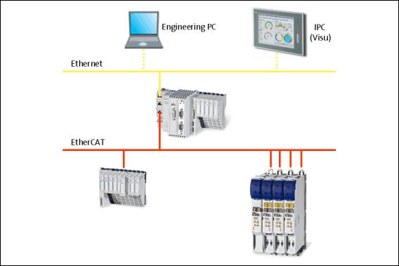
The Lenze automation system "Controller-based Automation" serves to create complex automation solutions with central motion control. Here, the Controller is the control centre of the system.
System structure of the Controller-based Automation: "All from one single source"
[3-1] Example: EtherCAT bus system with a 3231 C controller, a 1000 I/O system and an i700 servo inverter
14 |
Lenze · Controller-based Automation · EtherCAT® Communication Manual · DMS 6.4 EN · 04/2014 · TD17 |
3 Controller-based Automation: Central motion control
_ _ _ _ _ _ _ _ _ _ _ _ _ _ _ _ _ _ _ _ _ _ _ _ _ _ _ _ _ _ _ _ _ _ _ _ _ _ _ _ _ _ _ _ _ _ _ _ _ _ _ _ _ _ _ _ _ _ _ _ _ _ _ _
Lenze provides especially coordinated system components:
•Engineering software
The Lenze Engineering tools ( 29) on your Engineering PC (Windows operating system ) serve to parameterise, configure and diagnose the system. The Engineering PC communicates with the Controller via Ethernet.
•Controller
The Lenze Controller is available as Panel Controller with integrated touch display and as Cabinet Controller in control cabinet design.
Cabinet Controllers provide a direct coupling of the I/O system 100 via the integrated backplane bus.
The runtime software of the Lenze Controllers provides the control and/or visualisation of motion sequences. The following software versions are available:
•"Logic": Sequence control in the Controller, motion control in the inverter
•"Motion": Sequence control and motion control in the Controller, inverter as actuating drive
•"Visu": Optional visualisation of the automation system, can be used separately or in addition to "Logic" or "Motion"
An external monitor panel/display can be connected to the Cabinet Controller 3231 C/ 3241 C.
•Without software: Controller as single component with operating system only
•Bus systems
EtherCAT is a standard "on board" bus system of the Controller-based Automation. EtherCAT enables the control of all nodes (Motion/Logic) on one common fieldbus.
Optionally, CANopen, PROFIBUS and PROFINET can be used as extended topologies.
The Controllers c300/p300 have a CANopen interface "on board" as well (in addition to EtherCAT).
•Inverter (e.g. Servo Inverter i700)
"Logic & Motion" runtime software
The "Controller-based Automation" system allows for the central control of devices for Logic and Motion applications. The runtime software runs on the Controller.
In case of Logic applications, the sequence control is carried out in the Controller and the motion control is carried out in the inverter.
In case of Motion applications , the sequence control and motion control are carried out in the Controller. The inverter is used as actuating drive.
•Motion applications make special demands on the cycle time and real-time capability of the bus system between the Controller and the subordinate fieldbus nodes.
•this is for instance the case if the field devices, for example, are to move in a synchronised way or if position setpoints are to be transmitted.
Lenze · Controller-based Automation · EtherCAT® Communication Manual · DMS 6.4 EN · 04/2014 · TD17 |
15 |

3 Controller-based Automation: Central motion control
_ _ _ _ _ _ _ _ _ _ _ _ _ _ _ _ _ _ _ _ _ _ _ _ _ _ _ _ _ _ _ _ _ _ _ _ _ _ _ _ _ _ _ _ _ _ _ _ _ _ _ _ _ _ _ _ _ _ _ _ _ _ _ _
Fieldbus communication
The Lenze Controllers have different interfaces for fieldbus communication:
Area |
|
Cabinet Controller |
|
Panel Controller |
||
|
c300 |
3221 C |
3231 C |
3241 C |
p300 |
p500 |
Interfaces (on board) |
|
|
|
|
|
|
Ethernet |
1 |
|
2 |
|
1 |
2 |
EtherCAT |
1 1) |
|
1 |
|
1 1) |
1 |
CANopen |
1 2) |
|
- |
|
1 2) |
- |
Optional interfaces (communication cards) |
|
|
|
|
||
CANopen |
- |
|
|
|
- |
|
MC-CAN2 |
|
|
|
|
|
|
PROFIBUS master |
- |
|
|
|
- |
|
MC-PBM |
|
|
|
|
|
|
PROFIBUS slave |
- |
|
|
|
- |
|
MC-PBS |
|
|
|
|
|
|
PROFINET device |
- |
|
|
|
- |
|
MC-PND |
|
|
|
|
|
|
|
|
|
|
|
|
|
1)In preparation
2)Only the CAN master functionality is supported.
The Ethernet interface serves to connect the Engineering PC or to create line topologies (no integrated switch for Controller c300/p300).
More information on the bus systems and configuration can be found in the communication manuals:
•Controller-based Automation EtherCAT®
•Controller-based Automation CANopen®
•Controller-based Automation PROFIBUS®
•Controller-based Automation PROFINET®
16 |
Lenze · Controller-based Automation · EtherCAT® Communication Manual · DMS 6.4 EN · 04/2014 · TD17 |
4 The Lenze automation system with EtherCAT
4.1Brief description of EtherCAT
_ _ _ _ _ _ _ _ _ _ _ _ _ _ _ _ _ _ _ _ _ _ _ _ _ _ _ _ _ _ _ _ _ _ _ _ _ _ _ _ _ _ _ _ _ _ _ _ _ _ _ _ _ _ _ _ _ _ _ _ _ _ _ _
4 |
The Lenze automation system with EtherCAT |
This chapter provides basic information about ...
•the structure of the Lenze automation system using the EtherCAT bus system;
•the Lenze Engineering tools required for commissioning;
•the interaction of the components.
4.1Brief description of EtherCAT
Tip!
Detailed information on EtherCAT is provided on the Internet website of the EtherCAT Technology Group:
www.ethercat.org
Product features
•EtherCAT is a high-performance bus system based on Ethernet.
•Due to its integrated synchronisation mechanisms based on "distributed clocks", EtherCAT possesses outstanding real time characteristics.
Synchronisation with "Distributed clocks" (DC) ( 36)
•EtherCAT provides a higher bandwidth compared to CANopen:
•This enables motion and logic applications to be operated by the same fieldbus.
•The number of the nodes to be controlled is higher.
•The maximally possible bus length is longer.
•EtherCAT can access all field devices via a common interface. Therefore, unlike for the Lenze CANopen control technology, a division into Logic bus and Motion bus is not required.
•The "Modular Device Profile for IPC" (MDP) is based on the "Modular Device Profile Specification" of the EtherCAT Technology Group. All (software and hardware) components of the Lenze Controller or Embedded PC are divided into modules. The list of the modules available is generated dynamically, depending on the physically available components. The Lenze I/O system 1000 with the EPM-S130 head end supports the "Modular Device Profile".
Lenze · Controller-based Automation · EtherCAT® Communication Manual · DMS 6.4 EN · 04/2014 · TD17 |
17 |
4 The Lenze automation system with EtherCAT
4.1Brief description of EtherCAT
_ _ _ _ _ _ _ _ _ _ _ _ _ _ _ _ _ _ _ _ _ _ _ _ _ _ _ _ _ _ _ _ _ _ _ _ _ _ _ _ _ _ _ _ _ _ _ _ _ _ _ _ _ _ _ _ _ _ _ _ _ _ _ _
4.1.1Structure of the EtherCAT bus system
Basic structure
[4-1] Example: EtherCAT bus system with 3231 C controller and i700 servo inverter
Physical structure
An EtherCAT master can communicate with one or more nodes (slaves).
Internally, the EtherCAT bus has a ring topology. Since Ethernet cables are provided with a feed conductor and a return conductor within one cable, for the installer the topology seems to be a line. The last slave closes the ring.
Switches, hubs, or other infrastructure components known from the Ethernet standard must not be used because they impair the real-time performance.
18 |
Lenze · Controller-based Automation · EtherCAT® Communication Manual · DMS 6.4 EN · 04/2014 · TD17 |
4 The Lenze automation system with EtherCAT
4.1Brief description of EtherCAT
_ _ _ _ _ _ _ _ _ _ _ _ _ _ _ _ _ _ _ _ _ _ _ _ _ _ _ _ _ _ _ _ _ _ _ _ _ _ _ _ _ _ _ _ _ _ _ _ _ _ _ _ _ _ _ _ _ _ _ _ _ _ _ _
4.1.2Communication
Compared with conventional Ethernet, the collision-free transfer of telegrams on the fieldbus makes EtherCAT a real-time capable bus system.
Communication is always initiated by the EtherCAT master, i.e. the Lenze Controller. A telegram sent by the master passes through all EtherCAT slaves. The last slave of the communication chain sends the telegram back to the EtherCAT master. On the way back, the telegram is directly sent to the EtherCAT master, without being processed in the slaves.
When EtherCAT is used, data are transferred in so-called "EtherCAT frames". The fieldbus nodes only remove the data intended for them and do so while the EtherCAT frame is passing through the device. Output data are inserted into the frame at the same time. Read and write access is always carried out on a small section of the overall EtherCAT frame – the datagrams. This means that a frame does not have to be received completely before it is processed. Each datagram is passed on with minimal delay.
Lenze · Controller-based Automation · EtherCAT® Communication Manual · DMS 6.4 EN · 04/2014 · TD17 |
19 |

4 The Lenze automation system with EtherCAT
4.1Brief description of EtherCAT
_ _ _ _ _ _ _ _ _ _ _ _ _ _ _ _ _ _ _ _ _ _ _ _ _ _ _ _ _ _ _ _ _ _ _ _ _ _ _ _ _ _ _ _ _ _ _ _ _ _ _ _ _ _ _ _ _ _ _ _ _ _ _ _
4.1.2.1The EtherCAT state machine
Before communication via EtherCAT is possible, the fieldbus is scanned by the EtherCAT state machine when the installation is being powered up. The following illustration shows the possible status changes from the point of view of an EtherCAT slave.
Init
Pre-Operational
Safe-Operational
Operational
E94AYCET009
[4-2] EtherCAT state machine
State |
Description |
Init |
• Initialisation phase |
|
• No SDO/PDO communication with the slaves |
|
• Device can be detected by fieldbus scan |
Pre-operational |
• The fieldbus is active. |
|
• SDO communication (mailbox communication) is possible. |
|
• No PDO communication |
Safe-operational |
• SDO communication (mailbox communication) is possible. |
|
• PDO communication: |
|
• The input data in the process image are updated. |
|
• The output data from the process image are not transferred to the slaves. |
Operational |
Normal operation |
|
• SDO communication |
|
• PDO communication |
|
• Fieldbus synchronisation has been successful (if used) |
|
|
Note!
•A fieldbus scan is possible in any EtherCAT state.
Determining the physical EtherCAT configuration (fieldbus scan) ( 75)
•The SDO communication via the EtherCAT bus is only possible if at least the "PreOperational" state has been reached.
•Only in the transitional phases between states can bus nodes be in different states.
20 |
Lenze · Controller-based Automation · EtherCAT® Communication Manual · DMS 6.4 EN · 04/2014 · TD17 |
4 The Lenze automation system with EtherCAT
4.1Brief description of EtherCAT
_ _ _ _ _ _ _ _ _ _ _ _ _ _ _ _ _ _ _ _ _ _ _ _ _ _ _ _ _ _ _ _ _ _ _ _ _ _ _ _ _ _ _ _ _ _ _ _ _ _ _ _ _ _ _ _ _ _ _ _ _ _ _ _
AL Status Code
Possible errors during transitions between states are entered in the EtherCAT register "AL Status Code" (address 0x0134:0x0135).
AL Status Code |
Description |
[hex] |
|
0x0000 |
No error |
0x0011 |
Invalid status change requested |
0x0012 |
Unknown status requested |
0x0013 |
"Bootstrap" status is not supported |
0x0016 |
Invalid mailbox configuration "Pre-operational" |
0x001A |
Synchronisation error |
0x001B |
Sync manager watchdog |
0x001D |
Invalid output data configuration |
0x001E |
Invalid input data configuration |
0x002B |
Invalid input and output data |
0x0030 |
Invalid configuration of DC synchronisation |
0x9001 |
Firmware watchdog error |
0x9002 |
Mapping error |
|
|
Lenze · Controller-based Automation · EtherCAT® Communication Manual · DMS 6.4 EN · 04/2014 · TD17 |
21 |
4 The Lenze automation system with EtherCAT
4.1Brief description of EtherCAT
_ _ _ _ _ _ _ _ _ _ _ _ _ _ _ _ _ _ _ _ _ _ _ _ _ _ _ _ _ _ _ _ _ _ _ _ _ _ _ _ _ _ _ _ _ _ _ _ _ _ _ _ _ _ _ _ _ _ _ _ _ _ _ _
4.1.2.2Addressing of the slaves
The EtherCAT system uses two types of addressing for the slaves:
Auto-increment addressing
The auto-increment addressing is used by the master during the initialisation phase of the fieldbus. When the "Pre-Operational" state has been reached, the master uses the Fixed-Address addressing.
Fixed-address addressing
With the fixed-address addressing, the slaves are addressed via the station address distributed by the master during the start-up phase.
In the EtherCAT bus topology in »PLC Designer«, the first slave is given the address ’1001’, the second the address ’1002’ and so on. The EtherCAT addresses cannot be changed.
The EtherCAT address of the master is ’0’. Access to master objects with the address ’0’ is possible.
Example
The first slave of a configuration is given the following addresses ...
•’0’ due to the automatic incrementation procedure;
•’1001’ due to the fixed addressing procedure.
22 |
Lenze · Controller-based Automation · EtherCAT® Communication Manual · DMS 6.4 EN · 04/2014 · TD17 |
4 The Lenze automation system with EtherCAT
4.1Brief description of EtherCAT
_ _ _ _ _ _ _ _ _ _ _ _ _ _ _ _ _ _ _ _ _ _ _ _ _ _ _ _ _ _ _ _ _ _ _ _ _ _ _ _ _ _ _ _ _ _ _ _ _ _ _ _ _ _ _ _ _ _ _ _ _ _ _ _
4.1.2.3Working counter
Each EtherCAT datagram contains a working counter (WKC) which is incremented by each slave after the data have been processed successfully.
The working counter (WKC) can be used as a diagnostics option to check the processing of the EtherCAT telegrams by the slaves.
In each cycle, the Lenze Controller compares the expected value of the working counter with the value read back via the fieldbus. If the read-back value is smaller than the expected value, not all addressed slaves have been reached. The controller detects this and reports an error.
Messages: WKC Error / Not all slaves "Operational" / SyncManager Watchdog ( 177)
Example
•10 slaves read/write process data in the "Operational" state Expected value of the WKC: 10
•A cable break between the 8th and 9th slave causes the master to be unable to access slave 9 and slave 10:
•Value of the restored WKC: 8
•An error response is initiated in the Lenze Controller.
•The EtherCAT bus changes to the state "Pre-Operational".
Lenze · Controller-based Automation · EtherCAT® Communication Manual · DMS 6.4 EN · 04/2014 · TD17 |
23 |
4 The Lenze automation system with EtherCAT
4.2Required hardware components
_ _ _ _ _ _ _ _ _ _ _ _ _ _ _ _ _ _ _ _ _ _ _ _ _ _ _ _ _ _ _ _ _ _ _ _ _ _ _ _ _ _ _ _ _ _ _ _ _ _ _ _ _ _ _ _ _ _ _ _ _ _ _ _
4.2Required hardware components
4.2.1Field devices
The Lenze automation system supports the following EtherCAT-capable logic and motion components:
Field devices |
|
|
EtherCAT |
|
|
|
Logic |
|
Motion |
Controller |
Controller 32xx C |
|
|
|
|
|
|
|
|
|
Controller c300 |
|
|
|
|
|
|
|
|
|
Controller p300 |
|
|
|
|
|
|
|
|
|
Controller p500 |
|
|
|
i700 servo inverter |
Single axis |
|
|
|
|
|
|
|
|
|
Double axis |
|
|
|
Servo Drives 9400 1) |
HighLine |
|
|
|
|
|
|
|
|
|
Highline with CiA402 |
|
|
|
|
|
|
|
|
|
PLC |
|
|
|
|
|
|
|
|
|
Regenerative power supply |
|
|
|
|
module |
|
|
|
Inverter Drives 8400 2) |
StateLine |
|
|
|
|
|
|
|
|
|
HighLine |
|
|
|
|
|
|
|
|
|
TopLine |
|
|
|
I/O-System 1000 |
EPM-Sxxx |
|
|
|
|
|
|
|
|
1)With EtherCAT E94AYCET communication module
2)With EtherCAT E84AYCET communication module
Field devices of other manufacturers can be integrated as Logic nodes if they provide a standardcompliant EtherCAT device description.
24 |
Lenze · Controller-based Automation · EtherCAT® Communication Manual · DMS 6.4 EN · 04/2014 · TD17 |

4 The Lenze automation system with EtherCAT
4.2Required hardware components
_ _ _ _ _ _ _ _ _ _ _ _ _ _ _ _ _ _ _ _ _ _ _ _ _ _ _ _ _ _ _ _ _ _ _ _ _ _ _ _ _ _ _ _ _ _ _ _ _ _ _ _ _ _ _ _ _ _ _ _ _ _ _ _
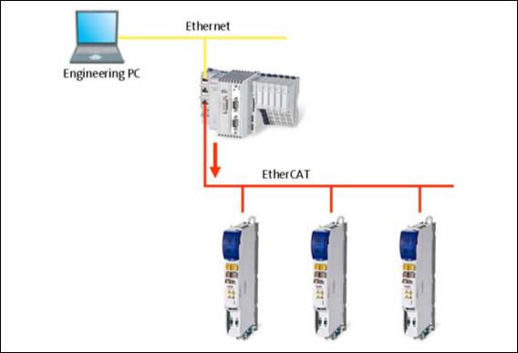
4.2.2The Lenze Controller - the central component
[4-3] Example: EtherCAT bus system with 3231 C controller as gateway and i700 servo inverter
The Lenze Controller is the central component in the EtherCAT bus system:
•The controller is the EtherCAT master.
•The Lenze Controllers have an EtherCAT interface "on-board".
•The controller acts as an EtherCAT gateway in order to enable access to the field devices from the Engineering PC via Ethernet and EtherCAT.
•The devices are interconnected successively in line. For correct operation, it is necessary that the physical sequence of the EtherCAT field devices matches the bus topology created in »PLC Designer«.
Otherwise the system will not become "Operational". (An error message indicates which slave (product code) is expected at what position.)
•Each EtherCAT slave has two EtherCAT ports.
In contrast to Ethernet, one port is assigned as input, the other one as output. The inputs (IN) and outputs (OUT) must be correctly wired to each other
•A bus termination at the last slave is not required since the bus system at the last slave is terminated automatically.
Lenze · Controller-based Automation · EtherCAT® Communication Manual · DMS 6.4 EN · 04/2014 · TD17 |
25 |

4 The Lenze automation system with EtherCAT
4.2Required hardware components
_ _ _ _ _ _ _ _ _ _ _ _ _ _ _ _ _ _ _ _ _ _ _ _ _ _ _ _ _ _ _ _ _ _ _ _ _ _ _ _ _ _ _ _ _ _ _ _ _ _ _ _ _ _ _ _ _ _ _ _ _ _ _ _
4.2.3 |
EtherCAT product codes |
|
|
|
|||||||
|
Device descriptions can be assigned to the corresponding devices with the help of the product |
||||||||||
|
codes. In »PLC Designer«, you can install device descriptions with the menu command Tools |
||||||||||
|
Device repository.... |
|
|
|
|
|
|||||
|
Importing missing devices / device description files ( 78) |
||||||||||
|
Structure of the device ID: <Manufacturer ID>_<Productcode><Revision number |
||||||||||
|
|
|
|
|
|
|
|
|
|
|
|
|
Identification |
|
|
|
|
|
|
Meaning |
|||
|
Manufacturer ID |
|
|
|
|
|
Unique identification for the manufacturer, for Lenze devices: 0x3B (59) |
||||
|
Product code |
|
|
|
|
|
|
Product code of the product range/the device |
|||
|
Revision number |
|
|
|
|
|
Revision number |
||||
|
If, for instance, a device available at the fieldbus without an installed device description is detected |
||||||||||
|
during a Determining the physical EtherCAT configuration (fieldbus scan) ( 75) a message with the |
||||||||||
|
device ID as hexadecimal value is displayed: |
||||||||||
|
In this example, the device description for a Lenze Servo Drive 9400 HighLine, actuating drive - |
||||||||||
|
speed, is not installed (0x38079CD9 = 940023001). |
||||||||||
|
Product codes for Servo Drives 9400 |
||||||||||
|
|
|
|
|
|
|
|
|
|
|
|
|
Product code [dec] |
|
|
|
|
Meaning |
|||||
|
9 |
4 |
0 |
0 |
2 |
1 |
x |
x |
x |
Servo Drive 9400 in general |
|
|
9 |
4 |
0 |
0 |
2 |
2 |
x |
x |
x |
Servo Drive 9400 StateLine |
|
|
9 |
4 |
0 |
0 |
2 |
3 |
x |
x |
x |
Servo Drive 9400 HighLine |
|
|
9 |
4 |
0 |
0 |
2 |
4 |
x |
x |
x |
Servo Drive 9400 TopLine |
|
|
9 |
4 |
0 |
0 |
2 |
5 |
x |
x |
x |
Servo Drive 9400 PLC |
|
|
9 |
4 |
0 |
0 |
2 |
6 |
x |
x |
x |
Servo Drive 9400 V/R (regenerative power supply module) |
|
|
|
|
|
|
|
|
|
|
|
|
|
|
|
|
|
|
|
|
|
|
|
Applications: |
|
|
|
|
|
|
|
|
|
|
|
|
|
|
|
|
|
|
|
|
0 |
0 |
0 |
Empty application |
|
|
|
|
|
|
|
|
0 |
0 |
1 |
Actuating drive - speed |
|
|
|
|
|
|
|
|
0 |
0 |
2 |
Actuating drive - torque |
|
|
|
|
|
|
|
|
0 |
0 |
3 |
Electronic gearbox |
|
|
|
|
|
|
|
|
0 |
0 |
4 |
Synchronism with mark synchronisation |
|
|
|
|
|
|
|
|
0 |
0 |
5 |
Table positioning |
|
|
|
|
|
|
|
|
0 |
0 |
6 |
Positioning sequence control |
|
|
|
|
|
|
|
|
0 |
0 |
7 |
PLC application |
|
|
|
|
|
|
|
|
0 |
0 |
8 |
Reserved |
|
|
|
|
|
|
|
|
|
... |
|
... |
|
|
|
|
|
|
|
|
0 |
9 |
9 |
Reserved |
|
|
|
|
|
|
|
|
1 |
x |
x |
Reserved for device profiles |
|
|
|
|
|
|
|
|
1 |
0 |
1 |
CiA402 |
|
|
|
|
|
|
|
|
2 |
x |
x |
Reserved for Lenze applications |
|
|
|
|
|
|
|
|
2 |
0 |
1 |
Regenerative power supply module application |
|
|
|
|
|
|
|
|
|
|
|
|
|
26 |
Lenze · Controller-based Automation · EtherCAT® Communication Manual · DMS 6.4 EN · 04/2014 · TD17 |
4 The Lenze automation system with EtherCAT
4.2Required hardware components
_ _ _ _ _ _ _ _ _ _ _ _ _ _ _ _ _ _ _ _ _ _ _ _ _ _ _ _ _ _ _ _ _ _ _ _ _ _ _ _ _ _ _ _ _ _ _ _ _ _ _ _ _ _ _ _ _ _ _ _ _ _ _ _
Product codes for Inverter Drives 8400
Product code [dec] |
|
Meaning |
||||
8 |
4 |
0 |
0 |
2 |
2 |
Inverter Drive 8400 StateLine |
8 |
4 |
0 |
0 |
2 |
3 |
Inverter Drive 8400 HighLine |
8 |
4 |
0 |
0 |
2 |
4 |
Inverter Drive 8400 TopLine |
Product codes for i700 servo inverter |
||||||
Product code [hex] |
|
|
|
|
|
Meaning |
|||||
1 |
7 |
6 |
2 |
0 |
|
6 |
6 |
4 |
3 |
3 |
Single axis |
1 |
7 |
6 |
2 |
0 |
|
6 |
6 |
4 |
3 |
4 |
Double axis |
Product codes for the I/O system 1000 |
|||||||||||
|
|
|
|
|
|
|
|
|
|
|
|
Product code |
Meaning |
|
|
|
|
||||||
[dec] |
|
|
|
|
|
|
|
|
|
|
|
1 |
3 |
0 |
0 |
I/O system EPM-S130 |
|
||||||
|
|
|
|
|
|
|
|
|
|
|
|
Lenze · Controller-based Automation · EtherCAT® Communication Manual · DMS 6.4 EN · 04/2014 · TD17 |
27 |

4 The Lenze automation system with EtherCAT
4.2Required hardware components
_ _ _ _ _ _ _ _ _ _ _ _ _ _ _ _ _ _ _ _ _ _ _ _ _ _ _ _ _ _ _ _ _ _ _ _ _ _ _ _ _ _ _ _ _ _ _ _ _ _ _ _ _ _ _ _ _ _ _ _ _ _ _ _
4.2.4The EtherCAT interface of the Lenze Controller
The EtherCAT interface links the controller to an EtherCAT network.
Note!
In the case of a correct connection to the field devices, the LEDs of the EtherCAT interface are lit.
EtherCAT interface of the Lenze Controller ( 34)
Example
ETC1: EtherCAT network connection
[4-4] EtherCAT interface at the 3231 C controller
28 |
Lenze · Controller-based Automation · EtherCAT® Communication Manual · DMS 6.4 EN · 04/2014 · TD17 |
4 The Lenze automation system with EtherCAT
4.3Lenze Engineering tools
_ _ _ _ _ _ _ _ _ _ _ _ _ _ _ _ _ _ _ _ _ _ _ _ _ _ _ _ _ _ _ _ _ _ _ _ _ _ _ _ _ _ _ _ _ _ _ _ _ _ _ _ _ _ _ _ _ _ _ _ _ _ _ _
4.3Lenze Engineering tools
The Lenze Engineering tools enable the configuration and operation of controller-based Lenze automation systems according to individual requirements.
Use the corresponding Engineering tool applicable to the field device.
 »EASY Navigator«: Starting the suitable Engineering tool
The Lenze Engineering software consists of the Engineering tools optimised for the respective Engineering stage.
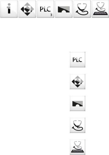
The »EASY Navigator« represents the Lenze Engineering tools installed on the Engineering PC. Start the desired Engineering tool via the corresponding button:
The »EASY Navigator« ...
•simplifies orientation for selecting the suitable Engineering tool;
•allows for the simple start of the required Engineering tool (depending on the application):
What would you like to do? |
Button |
Engineering tool |
Programming |
|
»PLC Designer« |
• Program the controller |
|
|
• Parameterise/commission the Servo-Inverter i700 |
|
|
• Parameterise the I/O system 1000 |
|
|
|
|
|
Parameterising/configuring the inverter |
|
»Engineer« |
• Parameterising and configuring the automation/drive |
|
|
system |
|
|
• Parameterising Inverter Drives 8400/Servo Drives 9400 |
|
|
|
|
|
Visualising |
|
»VisiWinNET« |
• Visualising the applications of the automation system |
|
|
• Creating the visualisation/user interfaces |
|
|
|
|
|
Online diagnostics |
|
»EASY Starter« |
• Easy online diagnostics of the controllers (from »EASY |
|
(reading parameters) |
Starter« V1.2) and other Lenze devices |
|
|
|
|
|
Online parameterisation |
|
»EASY Starter« |
• Online parameterisation/commissioning of Lenze |
|
(reading/writing |
devices |
|
parameters) |
• Direct online parameterisation when the online |
|
|
connection to the Lenze devices is active. |
|
|
|
|
|
Further Engineering tools that are not called via the »EASY Navigator« are:
•»WebConfig« (web-based parameterisation, configuration, and online diagnostics)
•»Backup & Restore« (data backup/recovery, software update).
Lenze · Controller-based Automation · EtherCAT® Communication Manual · DMS 6.4 EN · 04/2014 · TD17 |
29 |

4 The Lenze automation system with EtherCAT
4.4Interaction of the components
_ _ _ _ _ _ _ _ _ _ _ _ _ _ _ _ _ _ _ _ _ _ _ _ _ _ _ _ _ _ _ _ _ _ _ _ _ _ _ _ _ _ _ _ _ _ _ _ _ _ _ _ _ _ _ _ _ _ _ _ _ _ _ _
4.4Interaction of the components
4.4.1The state machine of the Lenze control technology
In the Lenze control technology, the states of the PLC and the EtherCAT bus are coupled. The PLC controls the fieldbus.
After switch-on, the system automatically powers up if the following conditions are fulfilled:
•There is an executable PLC boot project on the controller (»PLC Designer« project).
•The slaves that are on the fieldbus and have been configured in »PLC Designer« are accessible.
The following illustration shows the linkage of the states in the state machine of the Lenze control technology when the conditions for the automatic acceleration of the system are fulfilled (boot project with EtherCAT configuration):
[4-5] States in the Lenze control technology
Legend
|
Transitional state, automatic change to next state |
|
Stationary state, change to next state by external actions |
PLC |
State of the PLC |
|
|
EtherCAT |
State of the EtherCAT bus |
|
|
30 |
Lenze · Controller-based Automation · EtherCAT® Communication Manual · DMS 6.4 EN · 04/2014 · TD17 |
Loading...