


E84DGFCR
Table of contents
 Loading...
L
EDS84DMOTPNET
13395074
Ä.HSkä
Communication Manual
E84DGFCRxxx
PROFINET Communication Unit
8400 motec
L-force Communication

2 L EDS84DMOTPNET EN 2.0 - 11/2011

EDS84DMOTPNET EN 2.0 - 11/2011 L 3
Communication manual 8400 motec PROFINET
Contents
Contents
1 About this documentation . . . . . . . . . . . . . . . . . . . . . . . . . . . . . . . . . . . . . . . . . . . . . . . . . . . . . . . . . 5
1.1 Document history
. . . . . . . . . . . . . . . . . . . . . . . . . . . . . . . . . . . . . . . . . . . . . . . . . . . . . . . . . . . . . . . 7
1.2 Conventions used
. . . . . . . . . . . . . . . . . . . . . . . . . . . . . . . . . . . . . . . . . . . . . . . . . . . . . . . . . . . . . . . 8
1.3 Terminology used
. . . . . . . . . . . . . . . . . . . . . . . . . . . . . . . . . . . . . . . . . . . . . . . . . . . . . . . . . . . . . . . 9
1.4 Notes used
. . . . . . . . . . . . . . . . . . . . . . . . . . . . . . . . . . . . . . . . . . . . . . . . . . . . . . . . . . . . . . . . . . . . . . 10
2 Safety instructions
. . . . . . . . . . . . . . . . . . . . . . . . . . . . . . . . . . . . . . . . . . . . . . . . . . . . . . . . . . . . . . . .11
2.1 General safety and application notes
. . . . . . . . . . . . . . . . . . . . . . . . . . . . . . . . . . . . . . . . . . . . . 11
2.2 Device- and application-specific safety instructions
. . . . . . . . . . . . . . . . . . . . . . . . . . . . . . . 12
2.3 Residual hazards
. . . . . . . . . . . . . . . . . . . . . . . . . . . . . . . . . . . . . . . . . . . . . . . . . . . . . . . . . . . . . . . . 12
3 Product description
. . . . . . . . . . . . . . . . . . . . . . . . . . . . . . . . . . . . . . . . . . . . . . . . . . . . . . . . . . . . . . . 13
3.1 Application as directed
. . . . . . . . . . . . . . . . . . . . . . . . . . . . . . . . . . . . . . . . . . . . . . . . . . . . . . . . . . 13
3.2 Features and variants
. . . . . . . . . . . . . . . . . . . . . . . . . . . . . . . . . . . . . . . . . . . . . . . . . . . . . . . . . . . 14
3.3 Connections and interfaces
. . . . . . . . . . . . . . . . . . . . . . . . . . . . . . . . . . . . . . . . . . . . . . . . . . . . . . 15
4 Technical data
. . . . . . . . . . . . . . . . . . . . . . . . . . . . . . . . . . . . . . . . . . . . . . . . . . . . . . . . . . . . . . . . . . . . 17
4.1 General data and operating conditions
. . . . . . . . . . . . . . . . . . . . . . . . . . . . . . . . . . . . . . . . . . . 17
4.2 Protocol data
. . . . . . . . . . . . . . . . . . . . . . . . . . . . . . . . . . . . . . . . . . . . . . . . . . . . . . . . . . . . . . . . . . . 18
4.3 Communication time
. . . . . . . . . . . . . . . . . . . . . . . . . . . . . . . . . . . . . . . . . . . . . . . . . . . . . . . . . . . . 18
4.4 Internal switch latency
. . . . . . . . . . . . . . . . . . . . . . . . . . . . . . . . . . . . . . . . . . . . . . . . . . . . . . . . . . 19
5 Installation
. . . . . . . . . . . . . . . . . . . . . . . . . . . . . . . . . . . . . . . . . . . . . . . . . . . . . . . . . . . . . . . . . . . . . . . 20
5.1 Mechanical installation
. . . . . . . . . . . . . . . . . . . . . . . . . . . . . . . . . . . . . . . . . . . . . . . . . . . . . . . . . . 21
5.2 Electrical installation
. . . . . . . . . . . . . . . . . . . . . . . . . . . . . . . . . . . . . . . . . . . . . . . . . . . . . . . . . . . . 22
5.2.1 Network topology
. . . . . . . . . . . . . . . . . . . . . . . . . . . . . . . . . . . . . . . . . . . . . . . . . . . . . . . 22
5.2.2 PROFINET connection
. . . . . . . . . . . . . . . . . . . . . . . . . . . . . . . . . . . . . . . . . . . . . . . . . . . . 24
5.2.3 External voltage supply
. . . . . . . . . . . . . . . . . . . . . . . . . . . . . . . . . . . . . . . . . . . . . . . . . . 25
6 Commissioning
. . . . . . . . . . . . . . . . . . . . . . . . . . . . . . . . . . . . . . . . . . . . . . . . . . . . . . . . . . . . . . . . . . . 26
6.1 Before initial switch-on
. . . . . . . . . . . . . . . . . . . . . . . . . . . . . . . . . . . . . . . . . . . . . . . . . . . . . . . . . . 26
6.2 Configuring the PROFINET IO controller
. . . . . . . . . . . . . . . . . . . . . . . . . . . . . . . . . . . . . . . . . . 27
6.3 Setting the station name
. . . . . . . . . . . . . . . . . . . . . . . . . . . . . . . . . . . . . . . . . . . . . . . . . . . . . . . . 28
6.4 Setting the IP configuration
. . . . . . . . . . . . . . . . . . . . . . . . . . . . . . . . . . . . . . . . . . . . . . . . . . . . . . 30
6.4.1 Settings via the PROFINET configurator of the »Engineer«
. . . . . . . . . . . . . . . . . . 31
6.4.2 Setting via codes in the »Engineer«
. . . . . . . . . . . . . . . . . . . . . . . . . . . . . . . . . . . . . . . 33
6.5 Establishing an online connection via PROFINET with the Lenze »Engineer«
. . . . . . . . 35
6.6 Initial switch-on
. . . . . . . . . . . . . . . . . . . . . . . . . . . . . . . . . . . . . . . . . . . . . . . . . . . . . . . . . . . . . . . . . 37

Communication manual 8400 motec PROFINET
Contents
4 L EDS84DMOTPNET EN 2.0 - 11/2011
7 Data transfer . . . . . . . . . . . . . . . . . . . . . . . . . . . . . . . . . . . . . . . . . . . . . . . . . . . . . . . . . . . . . . . . . . . . . 38
8 Process data transfer
. . . . . . . . . . . . . . . . . . . . . . . . . . . . . . . . . . . . . . . . . . . . . . . . . . . . . . . . . . . . . . 39
8.1 Access to process data / PDO mapping
. . . . . . . . . . . . . . . . . . . . . . . . . . . . . . . . . . . . . . . . . . . 39
8.2 Port interconnection of the process data objects (PDO)
. . . . . . . . . . . . . . . . . . . . . . . . . . . . 40
8.3 Process input data AI/DI (Slot2)
. . . . . . . . . . . . . . . . . . . . . . . . . . . . . . . . . . . . . . . . . . . . . . . . . . 44
9 Parameter data transfer
. . . . . . . . . . . . . . . . . . . . . . . . . . . . . . . . . . . . . . . . . . . . . . . . . . . . . . . . . . . 45
9.1 The acyclic channel (PROFIdrive profile)
. . . . . . . . . . . . . . . . . . . . . . . . . . . . . . . . . . . . . . . . . . . 45
9.1.1 Connection establishment of an I/O controller to an I/O device
. . . . . . . . . . . . 45
9.1.2 Acyclic data transmission process
. . . . . . . . . . . . . . . . . . . . . . . . . . . . . . . . . . . . . . . . . 46
9.1.3 Structure of the PROFINET data telegram
. . . . . . . . . . . . . . . . . . . . . . . . . . . . . . . . . 47
9.2 Reading parameters from the controller
. . . . . . . . . . . . . . . . . . . . . . . . . . . . . . . . . . . . . . . . . . 48
9.2.1 Response after a correct read request
. . . . . . . . . . . . . . . . . . . . . . . . . . . . . . . . . . . . . 49
9.2.2 Response after a read error
. . . . . . . . . . . . . . . . . . . . . . . . . . . . . . . . . . . . . . . . . . . . . . . 50
9.2.3 Telegram example: Read request
. . . . . . . . . . . . . . . . . . . . . . . . . . . . . . . . . . . . . . . . . 51
9.3 Writing parameters to the controller
. . . . . . . . . . . . . . . . . . . . . . . . . . . . . . . . . . . . . . . . . . . . . 53
9.3.1 Response after a correct write request
. . . . . . . . . . . . . . . . . . . . . . . . . . . . . . . . . . . . 55
9.3.2 Response after a write error
. . . . . . . . . . . . . . . . . . . . . . . . . . . . . . . . . . . . . . . . . . . . . . 55
9.3.3 Telegram example: Write request
. . . . . . . . . . . . . . . . . . . . . . . . . . . . . . . . . . . . . . . . 57
9.4 Error information (error)
. . . . . . . . . . . . . . . . . . . . . . . . . . . . . . . . . . . . . . . . . . . . . . . . . . . . . . . . . 59
9.5 Consistent parameter data
. . . . . . . . . . . . . . . . . . . . . . . . . . . . . . . . . . . . . . . . . . . . . . . . . . . . . . 61
10 Monitoring
. . . . . . . . . . . . . . . . . . . . . . . . . . . . . . . . . . . . . . . . . . . . . . . . . . . . . . . . . . . . . . . . . . . . . . . 62
10.1 Interruption of PROFINET communication
. . . . . . . . . . . . . . . . . . . . . . . . . . . . . . . . . . . . . . . . 62
10.2 Internal communication fault
. . . . . . . . . . . . . . . . . . . . . . . . . . . . . . . . . . . . . . . . . . . . . . . . . . . . 63
11 Diagnostics
. . . . . . . . . . . . . . . . . . . . . . . . . . . . . . . . . . . . . . . . . . . . . . . . . . . . . . . . . . . . . . . . . . . . . . . 64
11.1 LED status displays
. . . . . . . . . . . . . . . . . . . . . . . . . . . . . . . . . . . . . . . . . . . . . . . . . . . . . . . . . . . . . . 64
11.2 Diagnostics with the »Engineer«
. . . . . . . . . . . . . . . . . . . . . . . . . . . . . . . . . . . . . . . . . . . . . . . . . 66
11.3 Diagnostic data
. . . . . . . . . . . . . . . . . . . . . . . . . . . . . . . . . . . . . . . . . . . . . . . . . . . . . . . . . . . . . . . . . 67
12 Error messages
. . . . . . . . . . . . . . . . . . . . . . . . . . . . . . . . . . . . . . . . . . . . . . . . . . . . . . . . . . . . . . . . . . . 68
12.1 Short overview of the PROFINET error messages
. . . . . . . . . . . . . . . . . . . . . . . . . . . . . . . . . . 68
12.2 Possible causes and remedies
. . . . . . . . . . . . . . . . . . . . . . . . . . . . . . . . . . . . . . . . . . . . . . . . . . . . 69
13 Parameter reference
. . . . . . . . . . . . . . . . . . . . . . . . . . . . . . . . . . . . . . . . . . . . . . . . . . . . . . . . . . . . . . . 73
13.1 Communication-relevant parameters of the operating system
. . . . . . . . . . . . . . . . . . . . . 73
13.2 Parameters relevant for PROFINET communication
. . . . . . . . . . . . . . . . . . . . . . . . . . . . . . . . 74
13.3 Table of attributes
. . . . . . . . . . . . . . . . . . . . . . . . . . . . . . . . . . . . . . . . . . . . . . . . . . . . . . . . . . . . . . 85
14 Index
. . . . . . . . . . . . . . . . . . . . . . . . . . . . . . . . . . . . . . . . . . . . . . . . . . . . . . . . . . . . . . . . . . . . . . . . . . . . 87

EDS84DMOTPNET EN 2.0 - 11/2011 L 5
Communication manual 8400 motec PROFINET
About this documentation
1 About this documentation
Contents
This documentation exclusively contains descriptions of the PROFINET bus system for the
Inverter Drive 8400 motec.
The properties and functions of PROFINET for Inverter Drives 8400 motec are described in
detail.
Examples illustrate typical applications.
This documentation also contains...
the most important technical data for PROFINET communication;
Information on the installation and commissioning of the PROFINET network;
Information on the PROFINET data transfer;
information on monitoring functions and troubleshooting as well as fault elimination.
The theoretical concepts are only explained to the level of detail required to understand
the function of PROFINET communication with Inverter Drives 8400 motec.
Depending on the software version of the controller and of the installed »Engineer«
software, the screenshots in this documentation may vary from the »Engineer« depiction.
This documentation does not describe any software provided by other manufacturers. No
liability can be accepted for corresponding data provided in this documentation. For
information on how to use the software, please refer to the host (master) documents.
All product names mentioned in this documentation are trademarks of their
corresponding owners.
Tip!
Detailed information on PROFINET can be found on the homepage of the PROFIBUS
user organisation which also develops the PROFINET communication technology:
www.profibus.com
Note!
This documentation supplements the mounting instructions and the "Inverter
Drives 8400 motec" hardware manual supplied with the controller.

Communication manual 8400 motec PROFINET
About this documentation
6 L EDS84DMOTPNET EN 2.0 - 11/2011
Target group
This documentation is aimed at people involved in configuring, installing, commissioning,
and maintaining the networking and remote maintenance of a machine.
Tip!
Information and software updates for Lenze products can be found in the
download area at:
www.Lenze.com
Validity information
The information in this documentation applies to the following devices:
Features and variants
( 14)
Product series Type designation Variant
Inverter Drives 8400 motec
PROFINET Communication Unit
E84DGFCRxNx PROFINET
E84DGFCRxJx PROFINET + Safety

EDS84DMOTPNET EN 2.0 - 11/2011 L 7
Communication manual 8400 motec PROFINET
About this documentation
Document history
1.1 Document history
Your opinion is important to us!
These instructions were created to the best of our knowledge and belief to give you the
best possible support for handling our product.
Perhaps we have not succeeded in achieving this objective in every respect. If you have
suggestions for improvement, please e-mail us to:
feedback-docu@Lenze.de
Thank you very much for your support.
Your Lenze documentation team
version Description
1.0 06/2011 TD17 First edition
2.0 11/2011 TD17 General revision
Communication manual 8400 motec PROFINET
About this documentation
Conventions used
8 L EDS84DMOTPNET EN 2.0 - 11/2011
1.2 Conventions used
This documentation uses the following conventions to distinguish different types of
information:
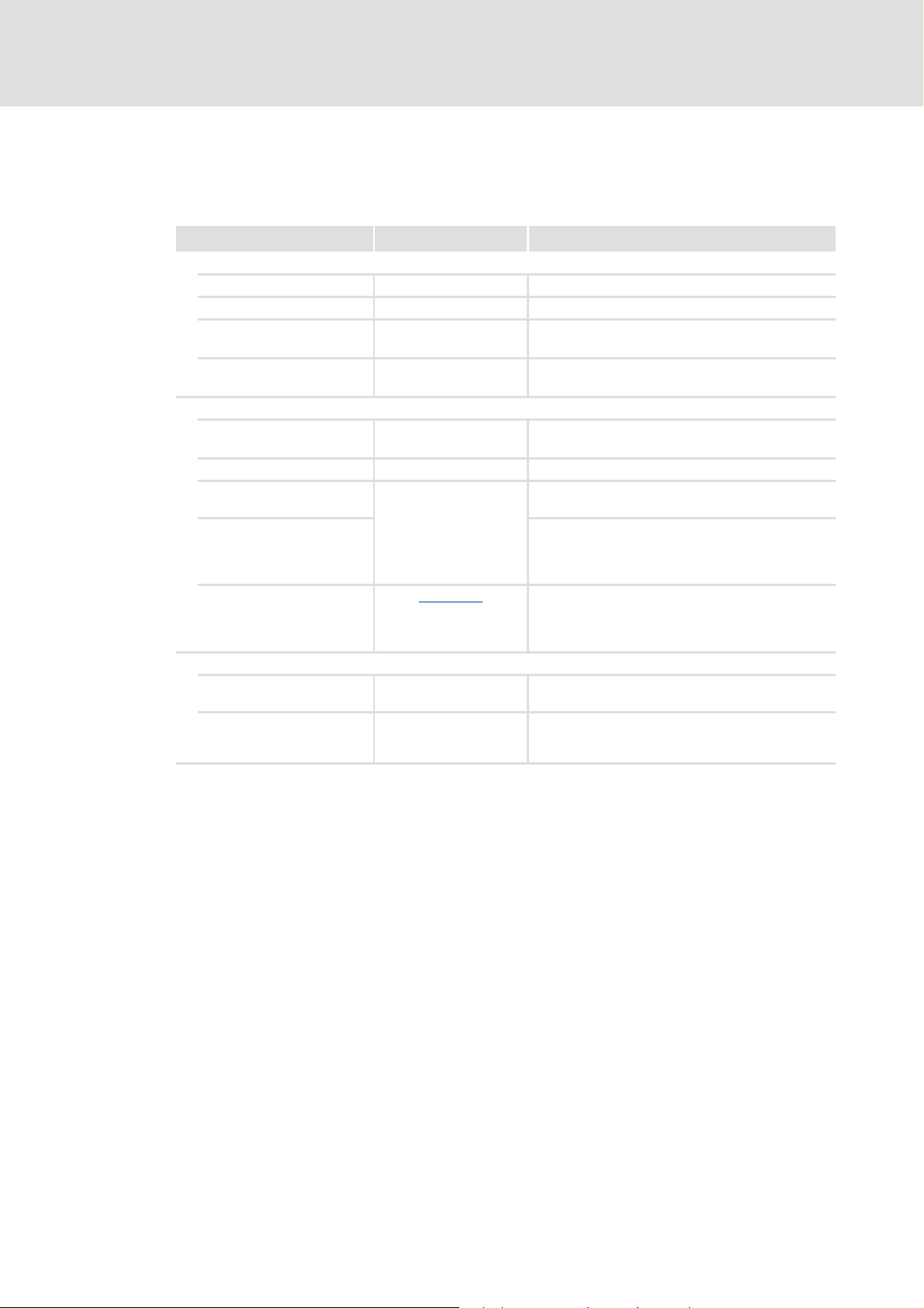
Type of information Writing Examples/notes
Numbers
Decimal Standard notation Example: 1234
Hexadecimal 0x[0 ... 9, A ... F] Example: 0x60F4
Binary
• Nibble
In inverted commas
Point
Example: ’100’
Example: ’0110.0100’
Decimal separator Point The decimal point is generally used.
Example: 1234.56
Text
Program name » « PC software
Example: Lenze »Engineer«
Window Italics The Message window... / The Options dialog box...
Control element Bold The OK button... / The Copy command... / The
Properties tab... / The Name input field...
Sequence of menu
commands
If the execution of a function requires several
successive commands, the individual commands are
separated from each other by an arrow: Select the
command File
Open to...
Hyperlink Underlined
Optically highlighted reference to another subject
which is activated with a mouse-click.
Symbols
Page reference ( 8) Optically highlighted reference to another page
which is activated with a mouse-click.
Step-by-step instructions
Step-by-step instructions are indicated by a
pictograph.

EDS84DMOTPNET EN 2.0 - 11/2011 L 9
Communication manual 8400 motec PROFINET
About this documentation
Terminology used
1.3 Terminology used
Term Meaning
Controller Lenze frequency inverter of the "Inverter Drives 8400 motec" product series
Standard device
Drive Unit
Communication Unit
Wiring Unit
The controller 8400 motec consists of the following modules: "Drive Unit",
"Communication Unit" and "Wiring Unit".
• The Drive Unit is available in various power classes.
• The Communication Unit is available in the following versions:
–No fieldbus
–AS-i option
–CANopen option
–PROFIBUS option
–PROFINET option
–EtherCAT option
• The Wiring Unit provides flexible connection options for an easy integration
into the power supply of the machine.
»Engineer« PC software from Lenze which supports you in "engineering" (parameter setting,
diagnosing, and configuring) during the entire life cycle, i.e. from planning to
maintenance of the commissioned machine.
Code Parameter which serves to parameterise and monitor the controller. In normal
usage, the term is usually referred to as "Index".
Subcode If a code contains several parameters they are stored in so-called "subcodes".
In the documentation the forward slash "/" is used as a separator between the
designation of the code and the subcode (e.g. "C00118/3").
In normal usage, the term is also referred to as "Subindex".
Lenze setting These are settings with which the device is preconfigured ex works.
Basic setting
HW Hardware
SW Software
I/O controller PROFINET master
The I/O controller takes over the master function for data communication of the
decentralised field devices. The I/O controller usually is the communication
interface of a PLC.
I/O device PROFINET slave
IO supervisor Engineering and diagnostics tools
The IO supervisor can access process data, diagnostic data, and alarm data.

Communication manual 8400 motec PROFINET
About this documentation
Notes used
10 L EDS84DMOTPNET EN 2.0 - 11/2011
1.4 Notes used
The following pictographs and signal words are used in this documentation to indicate
dangers and important information:
Safety instructions
Structure of the safety instructions:
Application notes
Pictograph and signal word!
(characterise the type and severity of danger)
Note
(describes the danger and gives information about how to prevent dangerous
situations)
Pictograph Signal word Meaning
Danger! Danger of personal injury through dangerous electrical voltage
Reference to an imminent danger that may result in death or serious
personal injury if the corresponding measures are not taken.
Danger! Danger of personal injury through a general source of danger
Reference to an imminent danger that may result in death or serious
personal injury if the corresponding measures are not taken.
Stop! Danger of damage to material assets
Reference to a possible danger that may result in damage to material assets
if the corresponding measures are not taken.
Pictograph Signal word Meaning
Note! Important note to ensure trouble-free operation
Tip! Useful tip for simple handling
Reference to another documentation

EDS84DMOTPNET EN 2.0 - 11/2011 L 11
Communication manual 8400 motec PROFINET
Safety instructions
General safety and application notes
2 Safety instructions
2.1 General safety and application notes
Lenze drive and automation components ...
– may only be used as directed.
Application as directed
( 13)
– must never be commissioned if they display any signs of damage.
– must never be technically modified.
– must never be commissioned if they are not fully mounted.
– must never be operated without the required covers.
– can - depending on their degree of protection - have live, movable or rotating parts
during operation and after operation. Surfaces can be hot.
For Lenze drive components ...
– Only use permissible accessories.
– use only original spare parts from the manufacturer.
Observe all the specifications contained in the enclosed and related documentation.
– This is the precondition for safe and trouble-free operation and for achieving the
specified product features.
Features and variants
( 14)
– The procedural notes and circuit details described in this document are only
proposals. It is up to the user to check whether they can be adapted to the particular
applications. Lenze does not take any responsibility for the suitability of the
procedures and circuit proposals described.
Note!
Always observe the specified safety measures to avoid severe injury to persons
and damage to property!
Always keep this documentation to hand in the vicinity of the product during
operation.
Danger!
Disregarding the following basic safety measures may lead to severe personal
injury and damage to material assets.

Communication manual 8400 motec PROFINET
Safety instructions
Device- and application-specific safety instructions
12 L EDS84DMOTPNET EN 2.0 - 11/2011
Only qualified personnel may work with and on Lenze drive and automation
components. In accordance with IEC 60364 and CENELEC HD 384, these are persons ...
– who are familiar with installing, mounting, commissioning, and operating the
product.
– who have the qualifications necessary for their occupation.
– who know all regulations for the prevention of accidents, directives and laws
applicable on site and are able to apply them.
2.2 Device- and application-specific safety instructions
During operation, the Communication Unit must be connected to the Wiring Unit and
the Drive Unit.
In case of external voltage supply, always use a separate power supply unit, safely
separated in accordance with EN 61800-5-1 in every control cabinet ("SELV" / "PELV").
2.3 Residual hazards
Device protection
The Communication Unit contains electronic components that can be damaged or
destroyed by electrostatic discharge.
Installation
( 20)
Documentation for "Inverter Drives 8400 motec", control system, plant/
machine
All the other measures prescribed in this documentation must also be
implemented. Observe the safety instructions and application notes stated in
this manual.

EDS84DMOTPNET EN 2.0 - 11/2011 L 13
Communication manual 8400 motec PROFINET
Product description
Application as directed
3 Product description
3.1 Application as directed
The PROFINET Communication Unit ...
is a unit that can only be used in conjunction with the following modules:
is an item of equipment intended for use in industrial power systems.
may only be operated under the operating conditions specified in this documentation.
may only be used in PROFINET networks.
can also be used without being connected to the PROFINET network.
Any other use shall be deemed inappropriate!
Product series Type designation
Inverter Drives 8400 motec
Drive Unit
E84DGDVxxxxxxxx
Inverter Drives 8400 motec
Wiring Unit
E84DGVNxx

Communication manual 8400 motec PROFINET
Product description
Features and variants
14 L EDS84DMOTPNET EN 2.0 - 11/2011
3.2 Features and variants
The PROFINET Communication Unit is available in the following versions:
The PROFINET Communication Unit is ...
– mounted to the Wiring Unit (E84DGVNxx);
– supplied internally via the Drive Unit (E84DGDVxxxxxxxx) or externally via a
separate voltage source.
The I/O connections can be brought into the device via M12 connectors or cable glands.
Devices without an integrated safety system (safety option) have no analog input and
no relay output.
The integrated safety system of the E84DGFCRxJx Communication Units can be used
on machines for the protection of persons.
Support of the I&M0...4 functionality for the identification of the standard device
Automatic detection of the baud rate 100 Mbps
A line topology is enabled by the integrated 2-port switch.
Support of the LLDP protocol for the topology recognition
Support of the SNMP protocol for diagnostic purposes
Exchange of up to 8 process data words per direction
Communication with the Lenze »Engineer« (access to all Lenze parameters) is executed
via the diagnostic interface of the Drive Unit.
An online connection via PROFINET is possible with the Lenze »Engineer«.
Product series Type designation Features
Enclosure
IP 65
PROFINET
M12
I/O: Terminal
I/O: M12
Safety
Inverter Drives 8400 motec
PROFINET Communication Unit
E84DGFCRANP zzz
E84DGFCR9NP zz z
E84DGFCRAJP zzz z
E84DGFCR9JP zz zz
"Inverter Drives 8400 motec" hardware manual
Here you will find detailed information on the integrated safety system (safety
option).
Software manual / »Engineer« online help for the "Inverter Drive 8400 motec"
Here you will find detailed information on how to configure the safety system
(safety option).
EDS84DMOTPNET EN 2.0 - 11/2011 L 15
Communication manual 8400 motec PROFINET
Product description
Connections and interfaces
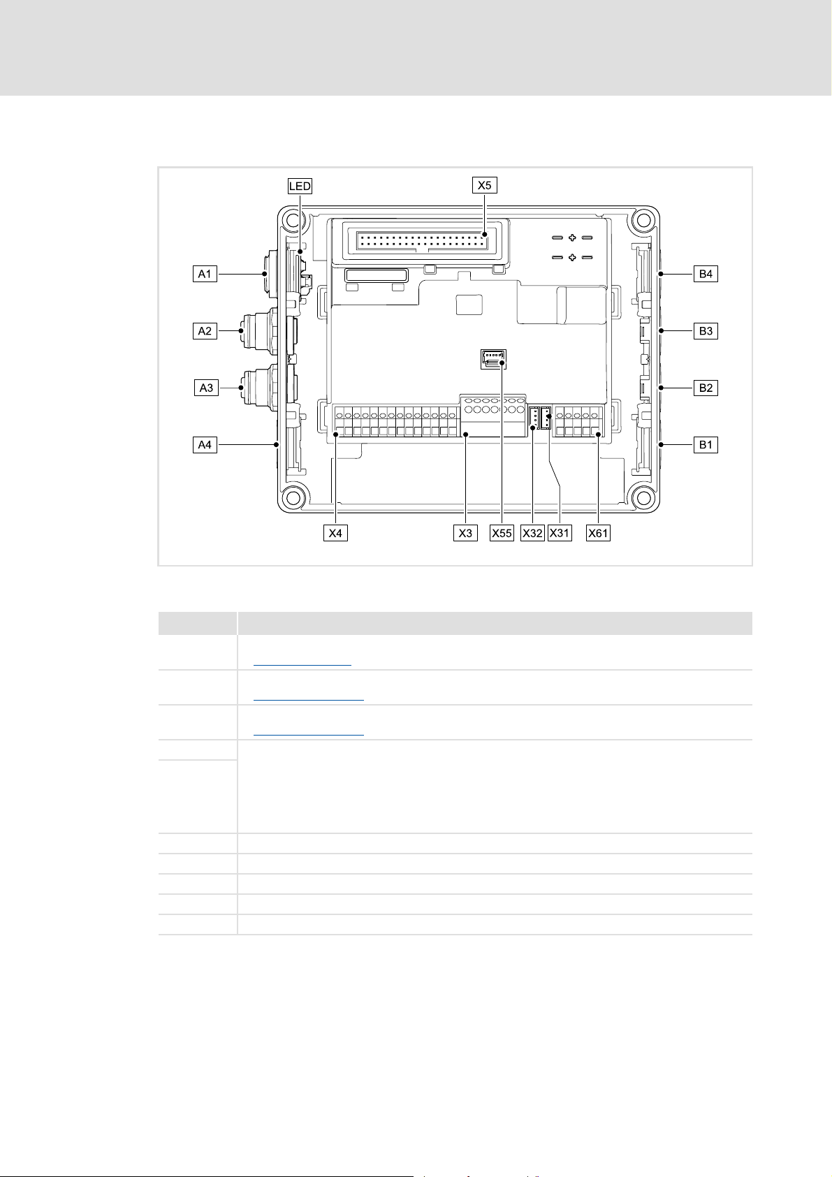
3.3 Connections and interfaces
[3-1] PROFINET Communication Unit
E84DG029
Pos. Description
A1 / LED Position for LEDs for PROFINET status display
LED status displays
( 64)
A2 PROFINET port 1 (M12 socket, 5-pole, D-coded)
PROFINET connection
( 24)
A3 PROFINET port 2 (M12 socket, 5-pole, D-coded)
PROFINET connection
( 24)
A4 Positions for further freely designable inputs and outputs:
• Digital inputs
•Digital output
• Analog input (only for E84DGFCRxJx)
• Relay output (only for E84DGFCRxJx)
• Connection of "Safety Option" safety system (only for E84DGFCRxJx)
B1 ... B4
X3 / X4 / X61 Terminal strips for wiring the connections at A4 and B1 ... B4
X5 Plug connector for connection to the Drive Unit
X31 Plug connector for wiring PROFINET port 1 at A2
X32 Plug connector for wiring PROFINET port 2 at A3
X55 Plug connector for wiring the LEDs at A1

Communication manual 8400 motec PROFINET
Product description
Connections and interfaces
16 L EDS84DMOTPNET EN 2.0 - 11/2011
By default, the PROFINET connections and the LEDs for the PROFINET status displays are
already mounted and wired:
– PROFINET port 1 at plug connector X31
– PROFINET port 2 at plug connector X32
– LEDs to plug connector X55
It is also possible to connect the PROFINET and other inputs and outputs (e.g. digital
inputs) via the positions A1 ... A4 and B1 ... B4.
For the connections, 5-pin M12 connectors or - alternatively - cable glands (cable cross-
section max. 1.0 mm
2
, AWG 18) can be used.
The M12 connectors, cable glands and prefabricated system cables can be obtained
from various manufacturers.
Wire the M12 connectors or cable glands used to the corresponding contacts of the
terminal strips/plug connectors X3, X4 and X61.
"Inverter Drives 8400 motec" hardware manual
Observe the notes and wiring instructions included.

EDS84DMOTPNET EN 2.0 - 11/2011 L 17
Communication manual 8400 motec PROFINET
Technical data
General data and operating conditions
4 Technical data
4.1 General data and operating conditions
"Inverter Drives 8400 motec" hardware manual
Here you will find the ambient conditions and information on the
electromagnetic compatibility (EMC) that also apply to the Communication
Unit.
Area Values
Order designation • E84DGFCRxNx (PROFINET)
• E84DGFCRxJx (PROFINET + Safety)
Communication profile PROFINET
Communication medium S/FTP (Screened Foiled Twisted Pair, ISO/IEC 11801 or EN 50173), CAT 5e
Interface for communication • PROFINET port 1: M12 socket, 5-pole, D-coded
• PROFINET port 2: M12 socket, 5-pole, D-coded
Network topology Tree, star, and line
Type of node I/O device with real time (RT) communication properties
Number of device nodes Max. 255 in the subnetwork
Max. cable length 100 m
PNO identification number 0x0106
Device identification (Device ID) 0x8440
Baud rate 100 Mbps
Switching method "Store and forward"
Switch latency Approx. 125 μs at max. telegram length
External voltage supply • U = 24 V DC (20 V - 0 % ... 29 V + 0 %)
•I
max
= 400 mA
Conformities, approvals • CE
•UR / cUR

Communication manual 8400 motec PROFINET
Technical data
Protocol data
18 L EDS84DMOTPNET EN 2.0 - 11/2011
4.2 Protocol data
4.3 Communication time
The communication time is the time between the start of a request and the arrival of the
corresponding response.
The communication times in a PROFINET network depend on the ...
Processing time inside the controller;
Transmission delay time (baud rate / telegram length);
Nesting depth of the network.
Processing time inside the controller
There are no interdependencies between parameter data and process data.
Area Values
Process data words slot 1 1 ... 8 process data words (max. 16 bytes)
Process data words slot 2
(for digital/analog inputs)
Optionally 0, 1, or 2 process data words (max. 4 bytes)
Process input data AI/DI (Slot2)
( 44)
Acyclic parameter channel Limited by the PROFINET frame size
Data Processing time
Process data Approx. 2 ms
+ 0 ... 1 ms
+ 1 ... x ms
update cycle
processing time in the module
application task runtime of the technology application used
(tolerance)
Parameter data Approx. 30 ms + a tolerance of 20 ms (typically)
• Some codes may require a longer processing time (see software manual/
»Engineer« online help for Inverter Drive 8400 motec).

EDS84DMOTPNET EN 2.0 - 11/2011 L 19
Communication manual 8400 motec PROFINET
Technical data
Internal switch latency
4.4 Internal switch latency
The integrated 2-port switch causes runtime delays which can be calculated as follows:
Example:
20 process data words => 40 bytes
((36 permanent bytes + 40 bytes) x 8 x 10 nsec) + 4 μsec
(76 bytes x 8 x 10 nsec) + 4 μsec
6.08 μsec + 4 μsec = 10.08 μsec
According to the PROFINET specification, the shortest PROFINET IO telegram must have a
data length of 72 bytes. If the 36 permanent bytes are subtracted from the 72 bytes, 36
bytes are available for process data. If now less than 36 bytes of process data are used, the
PROFINET IO telegram is filled with "zero bytes" until it can be transmitted. As a
consequence for the calculation formula, the shortest PROFINET I/O telegram with 18
process data words (36 bytes) has always the same length and thus the runtime delay is
the same, too.
Runtime delay = ((36 permanent bytes + process data in bytes) x 8 x 10 nsec) + 4 μsec
Note!
The use of external switches can also lead to runtime delays. Depending on the
system constellation, it may be useful to create a star topology or a line/mix
topology.
Network topology
( 22)

Communication manual 8400 motec PROFINET
Installation
20 L EDS84DMOTPNET EN 2.0 - 11/2011
5 Installation
Stop!
Electrostatic discharge
Electronic components within the Communication Unit can be damaged or
destroyed by electrostatic discharge.
Possible consequences:
• The Communication Unit is defective.
• Fieldbus communication is troubled or not possible.
• I/O signals are faulty.
• The safety function is faulty.
Protective measures
• Discharge electrostatic charges before touching the Communication Unit.
EDS84DMOTPNET EN 2.0 - 11/2011 L 21
Communication manual 8400 motec PROFINET
Installation
Mechanical installation
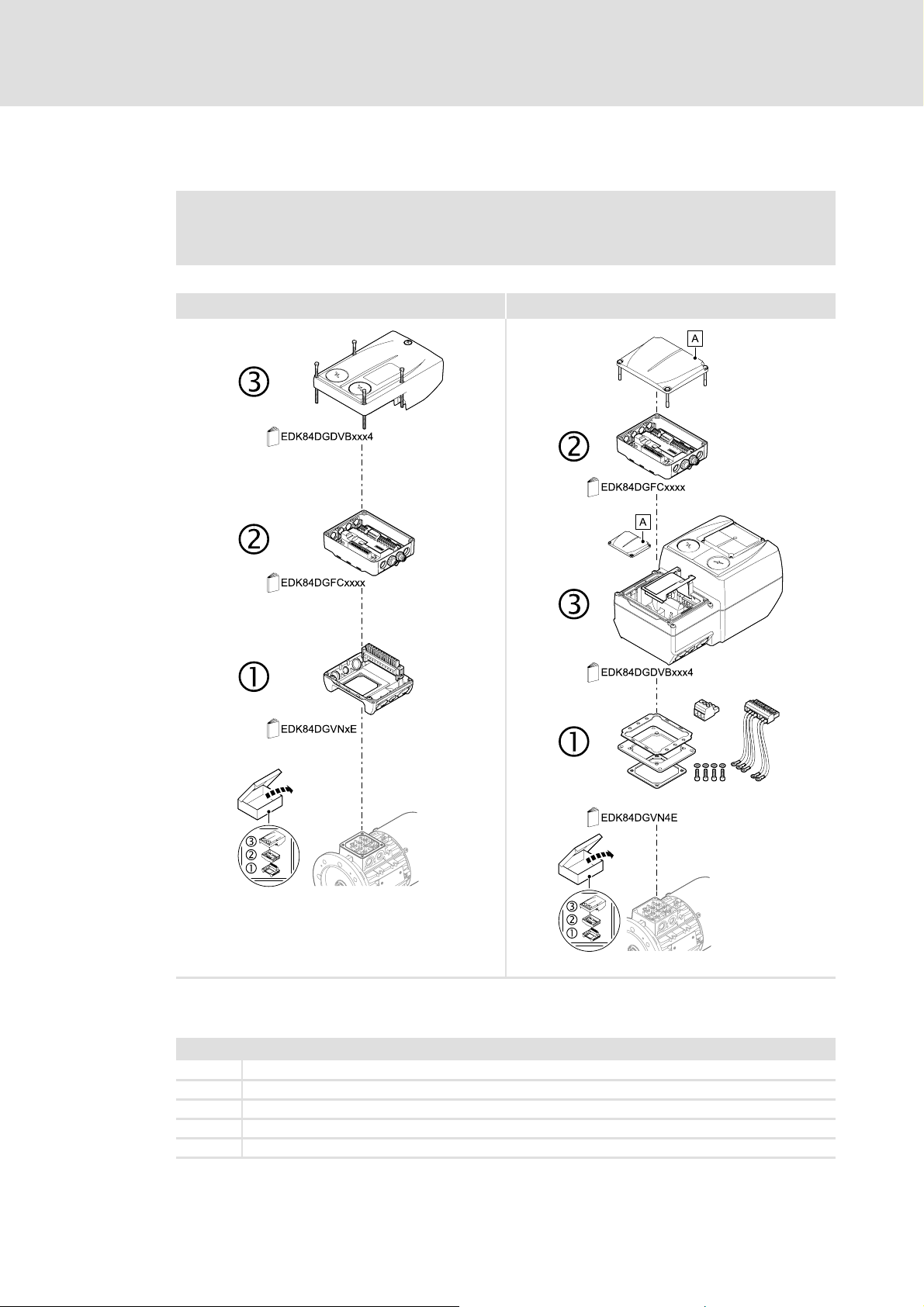
5.1 Mechanical installation
[5-1] Mechanical installation of the 8400 motec components
Mounting instructions for "Inverter Drives 8400 motec"
Here you will find detailed information on the installation.
0.37 ... 3.0 kW 4.0 ... 7.5 kW
E84DG023a
E84DG023b
Legend for Fig. [5-1]
1Drive Unit
2 Communication Unit
3 Wiring Unit
A Cover of the Drive Unit
EDK84DG... Mounting instructions for the Drive Unit, Communication Unit, Wiring Unit
Communication manual 8400 motec PROFINET
Installation
Electrical installation
22 L EDS84DMOTPNET EN 2.0 - 11/2011
5.2 Electrical installation
5.2.1 Network topology
It is typical of PROFINET to have a rather free topology the limiting factor of which is large
message latencies due to e.g. switches connected in series.
Internal switch latency
( 19)
The combination of a line and a stub is useful for system wiring.
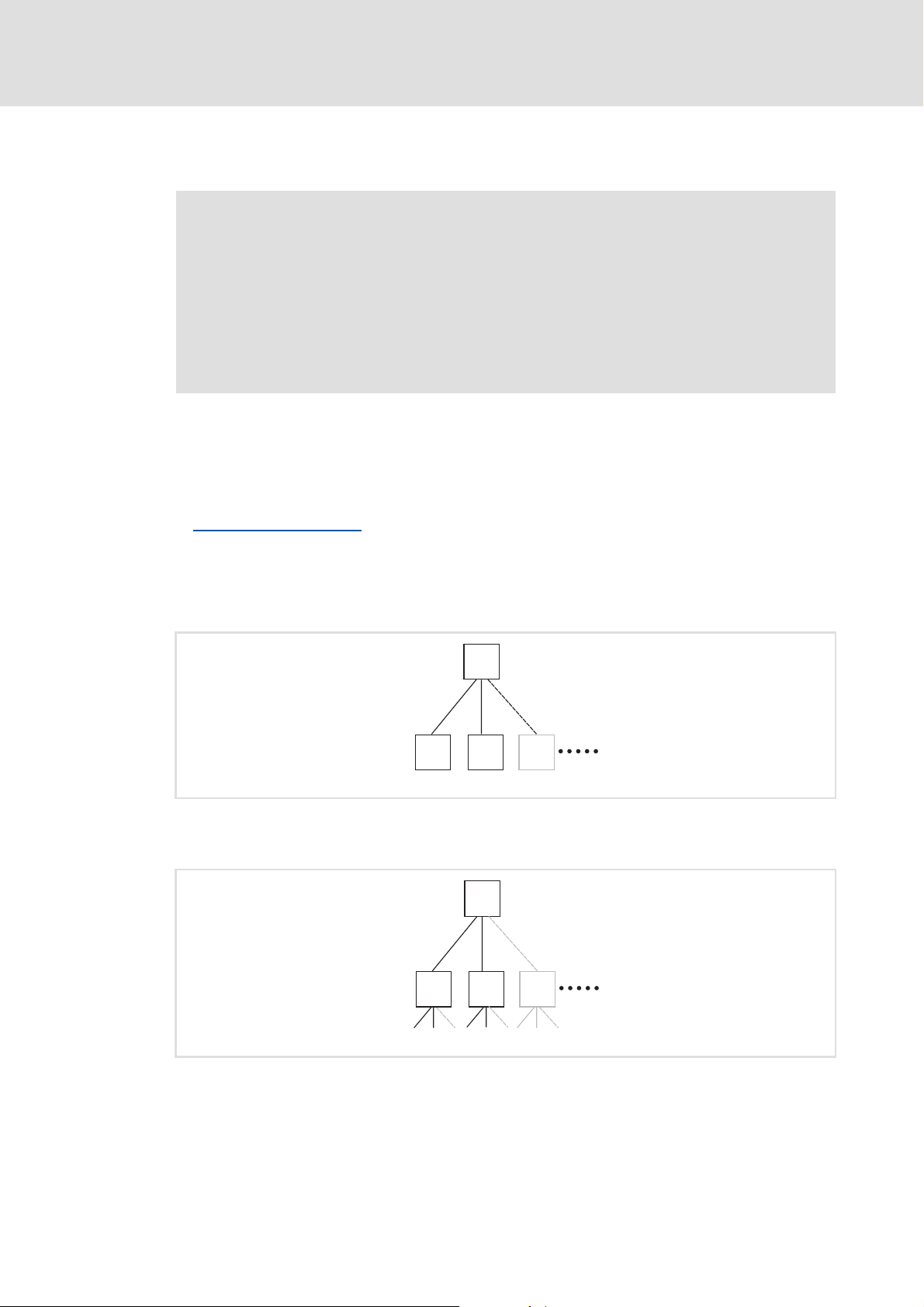
PROFINET supports the following topologies:
Switch / star
[5-2] Switch / star topology (S = switch, D = I/O device)
Tree via switches
[5-3] Tree topology (C =I/O controller, S = switch)
"Inverter Drives 8400 motec" hardware manual
Here you will find detailed information about ...
• the digital and analog inputs/outputs;
• the relay output;
• the integrated safety system (safety option);
• the wiring of the connections.
Observe the notes and wiring instructions included.
E94YCER005
S
D
DD
E94YCER006
C
S
SS
EDS84DMOTPNET EN 2.0 - 11/2011 L 23
Communication manual 8400 motec PROFINET
Installation
Electrical installation
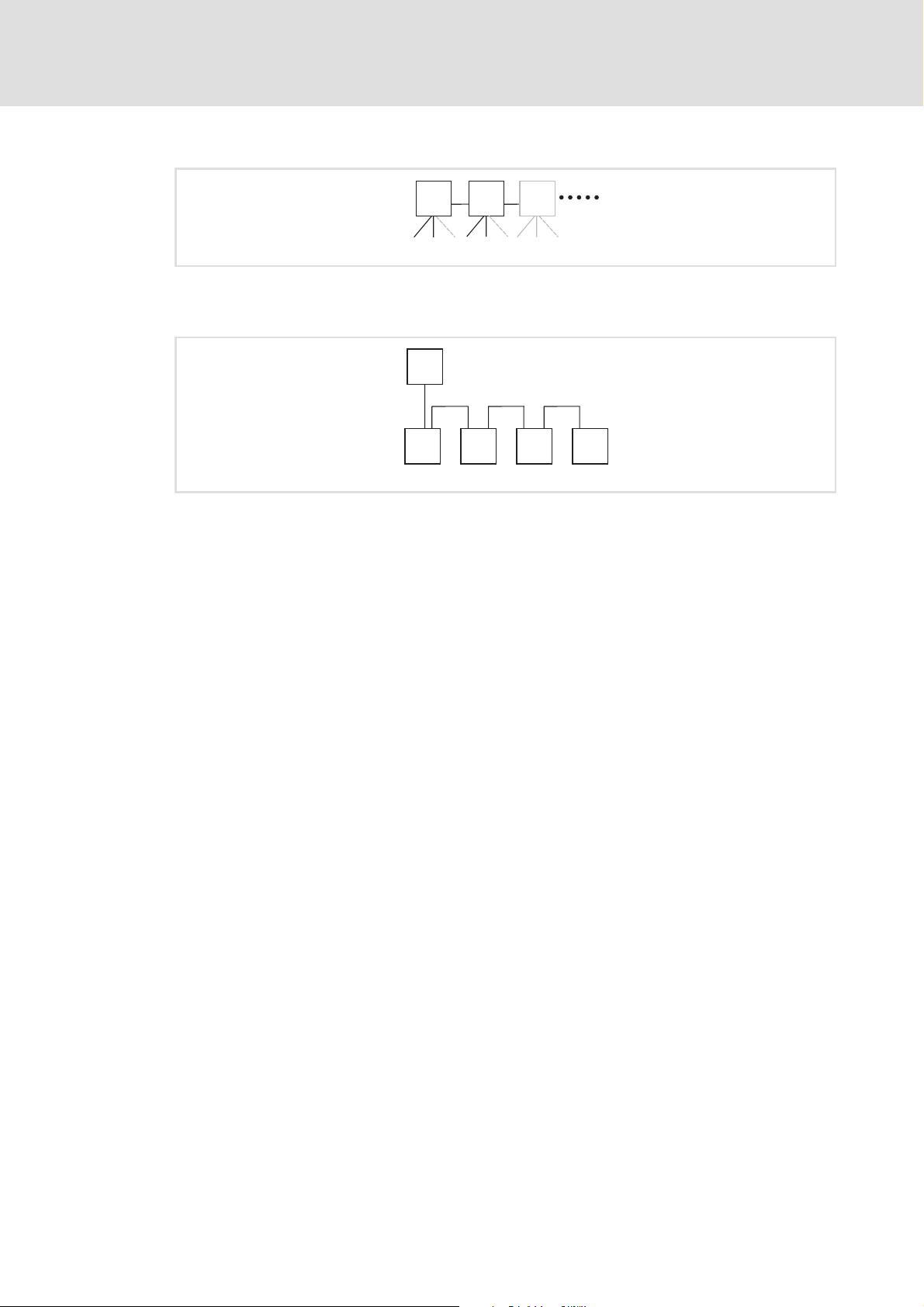
Switch / switch
[5-4] Switch/switch topology (S = switch)
I/O controller / I/O device
[5-5] Line topology (C = I/O controller, D = I/O device)
E94YCER007
SSS
E94YCER008
D D D D
C
Communication manual 8400 motec PROFINET
Installation
Electrical installation
24 L EDS84DMOTPNET EN 2.0 - 11/2011
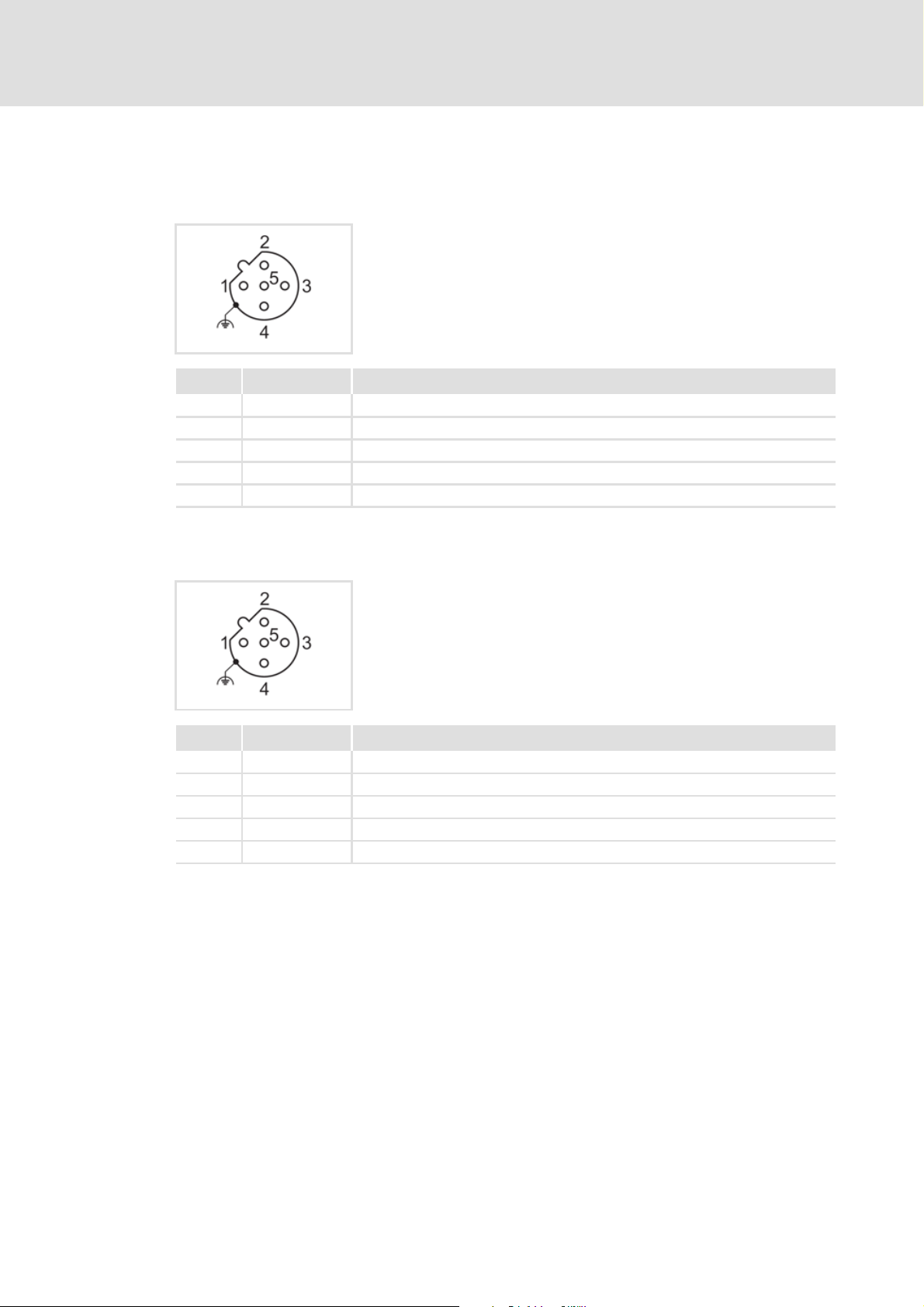
5.2.2 PROFINET connection
PROFINET port 1
PROFINET port 2
M12 socket, 5-pole, D-coded
Wiring at terminal strip X31
Pin Signal Description
1 Tx + Data line (transmitted data, plus)
2 Rx + Data line (received data, plus)
3 Tx - Data line (transmitted data, minus)
4 Rx - Data line (received data, minus)
5 - Not assigned
M12 socket, 5-pole, D-coded
Wiring at terminal strip X32
Pin Signal Description
1 Tx + Data line (transmitted data, plus)
2 Rx + Data line (received data, plus)
3 Tx - Data line (transmitted data, minus)
4 Rx - Data line (received data, minus)
5 - Not assigned

EDS84DMOTPNET EN 2.0 - 11/2011 L 25
Communication manual 8400 motec PROFINET
Installation
Electrical installation
5.2.3 External voltage supply
The external voltage supply can be used to establish PROFINET communication for
commissioning and to query the data of the digital and analog inputs.
Furthermore the external voltage supply serves to maintain PROFINET communication
if the main supply fails.
The digital inputs RFR, DI1 ... DI5 and the analog input can continue to be evaluated.
The external voltage supply is done via the terminals 24E and GND of the terminal strip
X3.
Permissible voltage (DC) / max. current:
– U = 24 V DC (20 V - 0 % ... 29 V + 0 %)
–I
max
= 400 mA
Access to parameters of a device that is disconnected from the mains is not possible.
"Inverter Drives 8400 motec" hardware manual
Here you can find detailed information on how to wire the Communication Unit.

Communication manual 8400 motec PROFINET
Commissioning
Before initial switch-on
26 L EDS84DMOTPNET EN 2.0 - 11/2011
6 Commissioning
During commissioning, system-related data such as motor parameters, operating
parameters, responses, and parameters for fieldbus communication are defined for the
controller. For Lenze devices, this is done via the codes.
The codes of the controller and communication are saved non-volatilely as a data set in the
memory module.
In addition to codes for the configuration, there are codes for diagnosing and monitoring
the nodes.
Parameter reference
( 73)
The data from the controller or the memory module can only be read with the main voltage
supply (400/500 V AC).
For commissioning with 24 V DC, only the data of the digital and analog inputs in the last
two data words are valid and readable (see Process input data AI/DI (Slot2)
( 44)).
6.1 Before initial switch-on
Stop!
Before you switch on the controller for the first time, check the entire wiring for
completeness, short circuit, and earth fault.
EDS84DMOTPNET EN 2.0 - 11/2011 L 27
Communication manual 8400 motec PROFINET
Commissioning
Configuring the PROFINET IO controller
6.2 Configuring the PROFINET IO controller
For communication with the PROFINET Communication Unit, the IO controller must be
configured first.
Configuration for device control
For the configuration of PROFINET, the current PROFINET device description file (XML) of
the Communication Unit has to be imported in the IO controller.
The device description file GSDML-Vx.z-Lenze-8440PNabb-yyyymmdd.xml can be found in
the download area at:
www.Lenze.com
Defining the user data length
The user data length is defined during the initialisation phase of the I/O controller.
The PROFINET Communication Unit supports the configuration of max. 8 process data
words (max. 16 bytes).
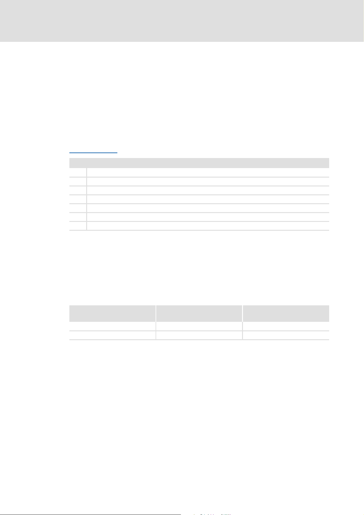
Description of the device data base file
Example of device data base file selection
"PCD (8W)" = 8 process data words in slot 1 of the PROFINET telegram
Wildcards in the file name "GSDML-Vx.z-Lenze-8440PN100-yyyymmdd.xml"
x Main version of the GSDML scheme used
z Subversion of the GSDML scheme used
A Major version of the software version
bb Minor version of the software version
yyyy Year
mm Month
dd Day
Selection text Process data Assigned
I/O memory
Slot 1: PCD (nW) 1 ... 8 words 0 ... 16 bytes
Slot 2: AI/DI (nW) 0 ... 2 words 0 ... 4 bytes
Loading...