


 Loading...
EDSMF2178IB
.Li|
Ä.Li|ä
L−force Communication
Communication Manual
CANopen
EMF2178IB
Communication module
l

iContents
1 |
About this documentation . . . . . . . . . . . . . . . . . . . . . . . . . . . . . . . . . . . . . . . . . . . . . . . . . . |
5 |
||
|
1.1 |
Document history . . . . . . . . . . . . . . . . . . . . . . . . . . . . . . . . . . . . . . . . . . . . . . . . . . . . |
7 |
|
|
1.2 |
Conventions used . . . . . . . . . . . . . . . . . . . . . . . . . . . . . . . . . . . . . . . . . . . . . . . . . . . . |
8 |
|
|
1.3 |
Terminology used . . . . . . . . . . . . . . . . . . . . . . . . . . . . . . . . . . . . . . . . . . . . . . . . . . . . |
9 |
|
|
1.4 |
Notes used . . . . . . . . . . . . . . . . . . . . . . . . . . . . . . . . . . . . . . . . . . . . . . . . . . . . . . . . . . |
10 |
|
2 |
Safety instructions . . . . . . . . . . . . . . . . . . . . . . . . . . . . . . . . . . . . . . . . . . . . . . . . . . . . . . . . . |
11 |
||
|
2.1 |
General safety information . . . . . . . . . . . . . . . . . . . . . . . . . . . . . . . . . . . . . . . . . . . . |
11 |
|
|
2.2 |
Device− and application−specific safety instructions . . . . . . . . . . . . . . . . . . . . . . . . |
12 |
|
|
2.3 |
Residual hazards . . . . . . . . . . . . . . . . . . . . . . . . . . . . . . . . . . . . . . . . . . . . . . . . . . . . . |
12 |
|
3 |
Product description . . . . . . . . . . . . . . . . . . . . . . . . . . . . . . . . . . . . . . . . . . . . . . . . . . . . . . . . |
13 |
||
|
3.1 |
Application as directed . . . . . . . . . . . . . . . . . . . . . . . . . . . . . . . . . . . . . . . . . . . . . . . |
13 |
|
|
3.2 |
Identification . . . . . . . . . . . . . . . . . . . . . . . . . . . . . . . . . . . . . . . . . . . . . . . . . . . . . . . . |
14 |
|
|
3.3 |
Product features . . . . . . . . . . . . . . . . . . . . . . . . . . . . . . . . . . . . . . . . . . . . . . . . . . . . . |
15 |
|
|
3.4 |
Connections and interfaces . . . . . . . . . . . . . . . . . . . . . . . . . . . . . . . . . . . . . . . . . . . . |
16 |
|
4 |
Technical data |
. . . . . . . . . . . . . . . . . . . . . . . . . . . . . . . . . . . . . . . . . . . . . . . . . . . . . . . . . . . . |
17 |
|
|
4.1 |
General data and operating conditions . . . . . . . . . . . . . . . . . . . . . . . . . . . . . . . . . |
17 |
|
|
4.2 |
Protective insulation . . . . . . . . . . . . . . . . . . . . . . . . . . . . . . . . . . . . . . . . . . . . . . . . . . |
18 |
|
|
4.3 |
Communication time . . . . . . . . . . . . . . . . . . . . . . . . . . . . . . . . . . . . . . . . . . . . . . . . . |
19 |
|
|
4.4 |
Dimensions . . . . . . . . . . . . . . . . . . . . . . . . . . . . . . . . . . . . . . . . . . . . . . . . . . . . . . . . . |
20 |
|
5 |
Installation . . |
. . . . . . . . . . . . . . . . . . . . . . . . . . . . . . . . . . . . . . . . . . . . . . . . . . . . . . . . . . . . . |
21 |
|
|
5.1 |
Mechanical installation . . . . . . . . . . . . . . . . . . . . . . . . . . . . . . . . . . . . . . . . . . . . . . . |
22 |
|
|
5.2 |
Electrical installation . . . . . . . . . . . . . . . . . . . . . . . . . . . . . . . . . . . . . . . . . . . . . . . . . . |
23 |
|
|
|
5.2.1 |
Wiring according to EMC (CE−typical drive system) . . . . . . . . . . . . . . . . . |
23 |
|
|
5.2.2 |
Wiring with a host (master) . . . . . . . . . . . . . . . . . . . . . . . . . . . . . . . . . . . . |
24 |
|
|
5.2.3 |
Wiring system bus (CAN) . . . . . . . . . . . . . . . . . . . . . . . . . . . . . . . . . . . . . . |
25 |
|
|
5.2.4 |
Specification of the transmission cable . . . . . . . . . . . . . . . . . . . . . . . . . . . |
26 |
|
|
5.2.5 |
Bus cable length . . . . . . . . . . . . . . . . . . . . . . . . . . . . . . . . . . . . . . . . . . . . |
27 |
|
|
5.2.6 |
Voltage supply . . . . . . . . . . . . . . . . . . . . . . . . . . . . . . . . . . . . . . . . . . . . . . |
30 |
6 |
Commissioning . . . . . . . . . . . . . . . . . . . . . . . . . . . . . . . . . . . . . . . . . . . . . . . . . . . . . . . . . . . |
32 |
||
|
6.1 |
Before switching on . . . . . . . . . . . . . . . . . . . . . . . . . . . . . . . . . . . . . . . . . . . . . . . . . . |
32 |
|
|
6.2 |
Installing EDS files . . . . . . . . . . . . . . . . . . . . . . . . . . . . . . . . . . . . . . . . . . . . . . . . . . . |
32 |
|
|
6.3 |
Setting node address and baud rate . . . . . . . . . . . . . . . . . . . . . . . . . . . . . . . . . . . . |
33 |
|
|
6.4 |
Initial switch−on . . . . . . . . . . . . . . . . . . . . . . . . . . . . . . . . . . . . . . . . . . . . . . . . . . . . . . |
36 |
|
|
6.5 |
Enable drive via the communication module . . . . . . . . . . . . . . . . . . . . . . . . . . . . . . |
37 |
|
2 |
l |
EDSMF2178IB EN 3.0

Contents i
7 |
Replacing the EMF2172IB communication module (CAN) . . . . . . . . . . . . . . . . . . . . . . . . |
39 |
||
8 |
Data transfer |
. . . . . . . . . . . . . . . . . . . . . . . . . . . . . . . . . . . . . . . . . . . . . . . . . . . . . . . . . . . . . |
42 |
|
|
8.1 |
Structure of the CAN telegram . . . . . . . . . . . . . . . . . . . . . . . . . . . . . . . . . . . . . . . . . |
42 |
|
|
8.2 |
CAN communication phases / network management (NMT) . . . . . . . . . . . . . . . |
45 |
|
9 |
Process data transfer . . . . . . . . . . . . . . . . . . . . . . . . . . . . . . . . . . . . . . . . . . . . . . . . . . . . . . . |
48 |
||
|
9.1 |
Available process data objects . . . . . . . . . . . . . . . . . . . . . . . . . . . . . . . . . . . . . . . . . . |
48 |
|
|
9.2 |
Configuring process data channel . . . . . . . . . . . . . . . . . . . . . . . . . . . . . . . . . . . . . . . |
50 |
|
|
9.3 |
Cyclic process data objects . . . . . . . . . . . . . . . . . . . . . . . . . . . . . . . . . . . . . . . . . . . . . |
51 |
|
|
|
9.3.1 |
Process data signals of Lenze controllers . . . . . . . . . . . . . . . . . . . . . . . . . |
52 |
|
|
9.3.2 |
Mapping in CANopen objects (I−160x, I−1A0x) . . . . . . . . . . . . . . . . . . . . . |
65 |
10 |
Parameter data transfer . . . . . . . . . . . . . . . . . . . . . . . . . . . . . . . . . . . . . . . . . . . . . . . . . . . . |
69 |
||
|
10.1 |
Access to the codes of the controller . . . . . . . . . . . . . . . . . . . . . . . . . . . . . . . . . . . . . |
70 |
|
|
10.2 |
Lenze parameter sets . . . . . . . . . . . . . . . . . . . . . . . . . . . . . . . . . . . . . . . . . . . . . . . . . |
71 |
|
|
|
10.2.1 Parameter sets for 8200 vector controller . . . . . . . . . . . . . . . . . . . . . . . . . |
71 |
|
|
|
10.2.2 Parameter sets for controller 93XX . . . . . . . . . . . . . . . . . . . . . . . . . . . . . . |
72 |
|
|
10.3 |
Structure of the parameter data telegram . . . . . . . . . . . . . . . . . . . . . . . . . . . . . . . . |
73 |
|
|
10.4 |
Error codes . . . . . . . . . . . . . . . . . . . . . . . . . . . . . . . . . . . . . . . . . . . . . . . . . . . . . . . . . . |
76 |
|
|
10.5 |
Examples of parameter data telegram . . . . . . . . . . . . . . . . . . . . . . . . . . . . . . . . . . . |
77 |
|
|
10.6 |
Special features for parameter setting of the drive controller . . . . . . . . . . . . . . . |
81 |
|
|
|
10.6.1 |
8200 vector controller . . . . . . . . . . . . . . . . . . . . . . . . . . . . . . . . . . . . . . . . . |
81 |
|
|
10.6.2 9300 Servo PLC / Drive PLC / ECS . . . . . . . . . . . . . . . . . . . . . . . . . . . . . . . . |
81 |
|
11 |
Monitoring . . |
. . . . . . . . . . . . . . . . . . . . . . . . . . . . . . . . . . . . . . . . . . . . . . . . . . . . . . . . . . . . . |
83 |
|
|
11.1 |
Heartbeat Protocol . . . . . . . . . . . . . . . . . . . . . . . . . . . . . . . . . . . . . . . . . . . . . . . . . . . |
83 |
|
|
11.2 |
Node Guarding Protocol . . . . . . . . . . . . . . . . . . . . . . . . . . . . . . . . . . . . . . . . . . . . . . . |
85 |
|
|
11.3 |
Emergency telegram . . . . . . . . . . . . . . . . . . . . . . . . . . . . . . . . . . . . . . . . . . . . . . . . . |
87 |
|
12 |
Diagnostics . . |
. . . . . . . . . . . . . . . . . . . . . . . . . . . . . . . . . . . . . . . . . . . . . . . . . . . . . . . . . . . . . |
88 |
|
|
12.1 |
Measures in case of troubled communication . . . . . . . . . . . . . . . . . . . . . . . . . . . . . |
88 |
|
|
12.2 |
LED status displays . . . . . . . . . . . . . . . . . . . . . . . . . . . . . . . . . . . . . . . . . . . . . . . . . . |
89 |
|
EDSMF2178IB EN 3.0
l 3

iContents
13 |
Implemented CANopen objects . . . . . . . . . . . . . . . . . . . . . . . . . . . . . . . . . . . . . . . . . . . . . . |
91 |
||
|
13.1 Reference between CANopen object and Lenze code . . . . . . . . . . . . . . . . . . . . . . . |
91 |
||
|
13.2 |
Overview . . . . . . . . . . . . . . . . . . . . . . . . . . . . . . . . . . . . . . . . . . . . . . . . . . . . . . . . . . . . |
92 |
|
|
|
13.2.1 |
I−1000: Device type . . . . . . . . . . . . . . . . . . . . . . . . . . . . . . . . . . . . . . . . . . . |
96 |
|
|
13.2.2 |
I−1001: Error register . . . . . . . . . . . . . . . . . . . . . . . . . . . . . . . . . . . . . . . . . |
96 |
|
|
13.2.3 |
I−1003: Error history . . . . . . . . . . . . . . . . . . . . . . . . . . . . . . . . . . . . . . . . . . |
97 |
|
|
13.2.4 |
I−1005: COB−ID SYNC message . . . . . . . . . . . . . . . . . . . . . . . . . . . . . . . . . |
98 |
|
|
13.2.5 |
I−1006: Communication cycle period . . . . . . . . . . . . . . . . . . . . . . . . . . . . |
99 |
|
|
13.2.6 |
I−1008: Manufacturer’s device name . . . . . . . . . . . . . . . . . . . . . . . . . . . . |
99 |
|
|
13.2.7 |
I−100A: Manufacturer software version . . . . . . . . . . . . . . . . . . . . . . . . . |
100 |
|
|
13.2.8 |
I−100C: Guard time . . . . . . . . . . . . . . . . . . . . . . . . . . . . . . . . . . . . . . . . . . . |
100 |
|
|
13.2.9 |
I−100D: Life time factor . . . . . . . . . . . . . . . . . . . . . . . . . . . . . . . . . . . . . . . |
101 |
|
|
13.2.10 |
I−1010: Store parameters . . . . . . . . . . . . . . . . . . . . . . . . . . . . . . . . . . . . . . |
101 |
|
|
13.2.11 |
I−1011: Restore default parameters . . . . . . . . . . . . . . . . . . . . . . . . . . . . . |
102 |
|
|
13.2.12 |
I−1014: COB−ID emergency object . . . . . . . . . . . . . . . . . . . . . . . . . . . . . . |
104 |
|
|
13.2.13 |
I−1015: Emergency inhibit time . . . . . . . . . . . . . . . . . . . . . . . . . . . . . . . . |
105 |
|
|
13.2.14 |
I−1016: Consumer heartbeat time . . . . . . . . . . . . . . . . . . . . . . . . . . . . . . |
105 |
|
|
13.2.15 |
I−1017: Producer heartbeat time . . . . . . . . . . . . . . . . . . . . . . . . . . . . . . . |
106 |
|
|
13.2.16 |
I−1018: Module device description . . . . . . . . . . . . . . . . . . . . . . . . . . . . . . |
106 |
|
|
13.2.17 |
I−1029: Error behaviour . . . . . . . . . . . . . . . . . . . . . . . . . . . . . . . . . . . . . . . |
106 |
|
|
13.2.18 |
I−1200/I−1201: Server SDO parameters . . . . . . . . . . . . . . . . . . . . . . . . . . |
107 |
|
|
13.2.19 |
I−1400 ... I−1402: Receive PDO communication parameters . . . . . . . . . |
109 |
|
|
13.2.20 |
I−1600 ... I−1602: Receive PDO mapping parameters . . . . . . . . . . . . . . . |
111 |
|
|
13.2.21 |
I−1800 ... I−1802: Transmit PDO communication parameters . . . . . . . . |
112 |
|
|
13.2.22 |
I−1A00 ... I−1A02: Transmit PDO mapping parameters . . . . . . . . . . . . . . |
114 |
14 |
Codes . . . . . . . |
. . . . . . . . . . . . . . . . . . . . . . . . . . . . . . . . . . . . . . . . . . . . . . . . . . . . . . . . . . . . . |
115 |
|
|
14.1 |
Overview . . . . . . . . . . . . . . . . . . . . . . . . . . . . . . . . . . . . . . . . . . . . . . . . . . . . . . . . . . . . |
115 |
|
|
14.2 |
Communication−relevant Lenze codes . . . . . . . . . . . . . . . . . . . . . . . . . . . . . . . . . . . |
119 |
|
|
14.3 |
Important controller codes . . . . . . . . . . . . . . . . . . . . . . . . . . . . . . . . . . . . . . . . . . . . . |
144 |
|
15 |
Index |
. . . . . . . |
. . . . . . . . . . . . . . . . . . . . . . . . . . . . . . . . . . . . . . . . . . . . . . . . . . . . . . . . . . . . . |
149 |
4 |
l |
EDSMF2178IB EN 3.0

About this documentation |
1 |
|
|
0Fig. 0Tab. 0
1About this documentation
Contents
This documentation exclusively contains descriptions of the EMF2178IB communication module (CANopen).
)Note!
This documentation supplements the mounting instructions supplied with the function/communication module and the documentation of the used standard device.
The mounting instructions contain safety instructions which must be observed!
The features and functions of the communication module are described in detail.
Examples illustrate typical applications.
Furthermore this documentation contains the following:
ƒSafety instructions that must be observed.
ƒKey technical data relating to the communication module
ƒInformation on versions of Lenze standard devices to be used.
ƒNotes on troubleshooting and fault elimination
The theoretical correlations are only explained in so far as they are necessary for comprehending the function of the communication module.
This documentation does not describe the software of an original equipment manufacturer. No responsibility is taken for corresponding information given in this manual. Information on how to use the software can be obtained from the documents of the host system (master).
All brand names mentioned in this manual are trademarks of their respective companies.
I Tip!
For further information visit the homepage of the CAN user organisation CiA (CAN in Automation): www.can−cia.org.
© 2013 Lenze Drives GmbH, Postfach 10 13 52, D−31763 Hameln
No part of this documentation may be reproduced or made accessible to third parties without written consent by Lenze Drives GmbH.
All information given in this documentation has been selected carefully and complies with the hardware and software described. Nevertheless, discrepancies cannot be ruled out. We do not take any responsibility or liability for any damage that may occur. Necessary corrections will be included in subsequent editions.
EDSMF2178IB EN 3.0
l 5

1About this documentation
Target group
This documentation is intended for all persons who plan, install, commission and maintain the networking and remote service of a machine.
I Tip!
Information and auxiliary devices related to the Lenze products can be found in the download area at
http://www.Lenze.com
Validity information
The information given in this documentation is valid for the following devices:
ƒ EMF2178IB communication modules (CANopen) as of version 1x.2x.
6 |
l |
EDSMF2178IB EN 3.0

About this documentation |
1 |
Document history
1.1Document history
Material no. |
Version |
|
|
Description |
|
|
− |
1.0 |
|
01/2008 |
TD17 |
First edition |
|
|
|
|
|
|
|
|
13127634 |
2.0 |
|
07/2011 |
TD17 |
General revision |
|
|
|
|
|
|
|
|
.Li| |
3.0 |
|
06/2013 |
TD17 |
l New chapter "Replacing communication module |
|
|
|
|
|
|
EMF2172IB (CAN)" (^ 39) |
|
|
|
|
|
|
l General updates |
|
Your opinion is important to us!
These instructions were created to the best of our knowledge and belief to give you the best possible support for handling our product.
If you have suggestions for improvement, please e−mail us to:
feedback−docu@Lenze.de
Thank you for your support.
Your Lenze documentation team
EDSMF2178IB EN 3.0
l 7

1About this documentation
Conventions used
1.2Conventions used
This documentation uses the following conventions to distinguish between different types of information:
Type of information |
Identification |
Examples/notes |
|
|
Spelling of numbers |
|
|
|
|
|
|
|
|
|
|
Decimal separator |
Point |
In general, the decimal point is used. |
|
|
|
|
For instance: 1234.56 |
|
|
Decimal |
Standard notation |
Example: 1234 |
|
|
|
|
|
|
|
Hexadecimal |
0x[0 ... 9, A ... F] |
Example: 0x60F4 |
|
|
|
|
|
|
|
Binary |
0b[0, 1] |
Example: ´0b0110´ |
|
|
l Nibble |
Point |
Example: ´0b0110.0100´ |
|
|
|
|
|
|
Text |
|
|
|
|
|
|
|
|
|
|
Program name |
» « |
PC software |
|
|
|
|
For example: »Engineer«, »Global Drive |
|
|
|
|
Control« (GDC) |
|
|
|
|
|
|
Icons |
|
|
|
|
|
|
|
|
|
|
Page reference |
^ |
Reference to another page with additional |
|
|
|
|
information |
|
|
|
|
For instance: ^ 16 = see page 16 |
|
|
|
|
|
|
|
Documentation reference |
, |
Reference to another documentation with |
|
|
|
|
additional information |
|
|
|
|
For example: ,EDKxxx = see |
|
|
|
|
documentation EDKxxx |
|
8 |
l |
EDSMF2178IB EN 3.0

About this documentation |
1 |
Terminology used
1.3Terminology used
Term |
Meaning |
|
Standard device |
Lenze controllers that can be used with the communication module. |
|
|
^ 13 |
|
Drive |
|
|
|
|
|
|
|
|
»Global Drive Control« / |
PC software from Lenze which supports you in "engineering" (parameter setting, |
|
»GDC« |
diagnosing, and configuring) during the entire life cycle, i.e. from planning to |
|
|
maintenance of the commissioned machine. |
|
|
|
|
Code |
Parameter which serves to parameterise and monitor the controller. In normal speech, |
|
|
the term is usually called "Index". |
|
|
|
|
Subcode |
If a code contains more than one parameter, these parameters are stored in |
|
|
"subcodes". |
|
|
In this documentation a slash "/" is used as a separator between code and subcode |
|
|
(e.g. "C00118/3"). |
|
|
In normal speech, the term is also called "Subindex". |
|
|
|
|
Lenze setting |
These are settings the device is preconfigured with ex works. |
|
|
|
|
Basic setting |
|
|
|
|
|
HW |
Hardware |
|
|
|
|
SW |
Software |
|
|
|
|
PDO |
Process data object |
|
|
|
|
SDO |
Service data object |
|
EDSMF2178IB EN 3.0
l 9

1About this documentation
Notes used
1.4Notes used
The following pictographs and signal words are used in this documentation to indicate dangers and important information:
Safety instructions
Structure of safety instructions:
} Danger!
(characterises the type and severity of danger)
Note
(describes the danger and gives information about how to prevent dangerous situations)
Pictograph and signal word |
Meaning |
|
{ Danger! |
Danger of personal injury through dangerous electrical voltage. |
|
Reference to an imminent danger that may result in death or |
|
|
serious personal injury if the corresponding measures are not |
|
|
|
taken. |
|
|
|
|
} Danger! |
Danger of personal injury through a general source of danger. |
|
Reference to an imminent danger that may result in death or |
|
|
serious personal injury if the corresponding measures are not |
|
|
|
taken. |
|
|
|
|
( Stop! |
Danger of property damage. |
|
Reference to a possible danger that may result in property |
|
|
damage if the corresponding measures are not taken. |
|
|
|
|
|
Application notes |
|
|
|
|
|
Pictograph and signal word |
Meaning |
|
) Note! |
Important note to ensure troublefree operation |
|
|
|
|
|
|
|
I Tip! |
Useful tip for simple handling |
|
|
|
|
|
|
|
, |
Reference to another documentation |
|
|
|
|
|
|
|
10 |
l |
EDSMF2178IB EN 3.0
Safety instructions |
2 |
General safety information
2Safety instructions
)Note!
It is absolutely vital that the stated safety measures are implemented in order to prevent serious injury to persons and damage to material assets.
Always keep this documentation to hand in the vicinity of the product during operation.
2.1General safety information
}Danger!
Disregarding the following basic safety measures may lead to severe personal injury and damage to material assets!
ƒLenze drive and automation components ...
... must only be used for the intended purpose.
... must never be operated if damaged.
... must never be subjected to technical modifications.
... must never be operated unless completely assembled.
... must never be operated without the covers/guards.
... can − depending on their degree of protection − have live, movable or rotating parts during or after operation. Surfaces can be hot.
ƒFor Lenze drive components ...
... only use permitted accessories.
... only use original manufacturer spare parts.
ƒAll specifications of the corresponding enclosed documentation must be observed.
This is vital for a safe and trouble−free operation and for achieving the specified product features.
The procedural notes and circuit details provided in this document are proposals which the user must check for suitability for his application. The manufacturer does not accept any liability for the suitability of the specified procedures and circuit proposals.
ƒOnly qualified skilled personnel are permitted to work with or on Lenze drive and automation components.
According to IEC 60364 or CENELEC HD 384, these are persons ...
... who are familiar with the installation, assembly, commissioning and operation of the product,
... possess the appropriate qualifications for their work,
... and are acquainted with and can apply all the accident prevent regulations, directives and laws applicable at the place of use.
EDSMF2178IB EN 3.0
l |
11 |

2Safety instructions
Device− and application−specific safety instructions
2.2Device− and application−specific safety instructions
ƒDuring operation, the communication module must be securely connected to the standard device.
ƒWith external voltage supply, always use a separate power supply unit, safely separated in accordance with EN 61800−5−1 in every control cabinet (SELV/PELV).
ƒOnly use cables that meet the given specifications. (¶ 26)
,Documentation of the standard device, control system, and plant/machine
All the other measures prescribed in this documentation must also be implemented. Observe the safety instructions and application notes contained in this manual.
2.3Residual hazards
Protection of persons
ƒIf controllers are connected to phase−earthed system with a rated mains voltage ³ 400 V, external measures need to be implemented to provide reliable protection against accidental contact. (see chapter "4.2", ^ 18)
Device protection
ƒThe communication module contains electronic components that can be damaged or destroyed by electrostatic discharge.
12 |
l |
EDSMF2178IB EN 3.0

Product description |
3 |
Application as directed
3Product description
3.1Application as directed
The communication module ...
ƒenables communication with Lenze controllers over the CAN bus with the CANopen communication profile.
ƒis a device intended for use in industrial power systems.
ƒcan be used in conjunction with the following Lenze controllers:
Series |
Device type |
Version |
Explanation |
|
|
|
|
HW |
SW 1) |
|
|
8200 vector |
E82xVxxxKxBxxxXX |
Vx |
1x |
8200 vector frequency inverter |
|
|
|
|
|
|
|
9300 |
EVS9321−xS ... EVS9332−xS |
2x |
1x |
Servo inverter |
|
|
|
|
|
|
|
|
EVS9321−xK ... EVS9332−xK |
2x |
1x |
Servo cam profiler |
|
|
|
|
|
|
|
|
EVS9321−xP ... EVS9332−xP |
2x |
1x |
Servo position controller |
|
|
|
|
|
|
|
|
EVS9321−xR ... EVS9332−xR |
2x |
1x |
Servo register controller |
|
|
|
|
|
|
|
|
EVS9321−xI ... EVS9332−xI |
2x |
8x |
9300 servo PLC |
|
|
|
|
|
|
|
|
EVS9321−xT ... EVS9332−xT |
2x |
8x |
|
|
|
|
|
|||
|
|
|
|
|
|
9300 vector |
EVF9321−xV ... EVF9333−xV |
2x |
1x |
9300 vector frequency inverter |
|
|
|
|
|
|
|
|
EVF9335−xV ... EVF9338−xV |
1x |
0x |
|
|
|
|
|
|
|
|
|
EVF9381−xV ... EVF9383−xV |
1x |
0x |
|
|
|
|
|
|
|
|
ECS servo |
ECSxSxxxC4xxxxXX |
1A |
6x |
"Speed and Torque" |
|
system |
|
|
|
|
|
ECSxPxxxC4xxxxXX |
1A |
6x |
"Posi and Shaft" |
|
|
|
|
||||
|
|
|
|
|
|
|
ECSxMxxxC4xxxxXX |
1A |
6x |
"Motion" |
|
|
|
|
|
|
|
|
ECSxAxxxC4xxxxXX |
1A |
6x |
"Application" |
|
|
|
|
|
|
|
Drive PLC |
EPL10200−xI ... EPL10203−xI |
1x |
8x |
Drive PLC |
|
1) Operating system software versions of the controllers
Any other use shall be deemed inappropriate!
EDSMF2178IB EN 3.0
l |
13 |

3Product description
Identification
3.2Identification
L |
|
Type |
|
Id.-No. |
|
Prod.-No. |
|
Ser.-No. |
|
E82AF000P0B201XX |
|
|
|
|
|
|
|
99371BC013 |
||
|
|
|
|
|
|
|
|
|
Type code |
• W |
33.2178IB |
1x |
2x |
|
|||
Series |
|
|
|
|
|
|
|
|
|
|
|
|
|
|
|
|
|
Hardware version |
|
|
|
|
|
|
|
|
|
|
|
|
|
|
|
|
|
Software version |
|
|
|
|
|
|
|
|
|
|
|
|
|
|
|
|
|
14 |
l |
EDSMF2178IB EN 3.0

Product description |
3 |
Product features
3.3Product features
ƒAttachable communication module for the basic Lenze devices 8200 vector, 93XX, 9300 Servo PLC, Drive PLC, ECSXX
ƒFront DIP switches for setting the ...
–CAN node address (max. 127 nodes)
–baud rate (10, 20, 50, 125, 250, 500 and 1000 kbit/s)
ƒBus expansion without repeater up to 7450 m
ƒTopology: Line terminated at both ends (R = 120 W)
ƒSimple connection through plug−on screw terminals
ƒTogether with a 9300 Servo PLC, additional CANopen application profiles can be implemented.
EDSMF2178IB EN 3.0
l |
15 |
3Product description
Connections and interfaces
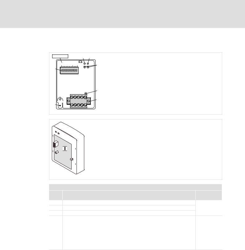
3.4Connections and interfaces
EMF2178IB |
|
|
|
Address Bd |
|
|
L |
|
|
|
CANopen |
CAN |
CAN |
|
||
GND |
LSHLD |
H |
V+ |
|
_ |
|
_ |
||
2178
2178CAN003
2102LEC007
Legend for fold−out page
Pos. |
Description |
Detailed |
|
|
information |
0Connection status to standard device (two−colour LED)
1 Connection status to fieldbus (two−colour LED) |
^ 89 |
2Operating status of standard device (green and red Drive LED)
3 |
Fixing screw |
|
|
|
|
4 |
Plug connector with double screw connection, 5−pole |
^ 24 |
|
|
|
5 |
PE shield cable connection |
|
|
|
|
6 |
DIP switches for setting the |
|
|
l node address (switches 1 ... 7) |
^ 33 |
|
l baud rate (switches 8 ... 10) |
|
|
|
|
8 |
Nameplate |
^ 14 |
16 |
l |
EDSMF2178IB EN 3.0

Technical data |
4 |
General data and operating conditions
4Technical data
4.1General data and operating conditions
Field |
Values |
|
Order designation |
EMF2178IB |
|
|
|
|
Communication media |
DIN ISO 11898 |
|
|
|
|
Network topology |
Line terminated at both ends (R = 120 W) |
|
|
|
|
Communication profile |
CANopen, DS301 V4.01 |
|
|
|
|
Node addresses |
Max. 127 |
|
|
|
|
Cable length |
Max. 7450 m (depending on the baud rate, ^ 27) |
|
|
|
|
Baud rate [kbit/s] |
10, 20, 50, 125, 250, 500, 1000 |
|
|
|
|
Voltage supply |
Internal or external supply possible for basic devices: 8200 vector / 93XX / |
|
|
9300 Servo PLC / Drive PLC / ECSXX |
|
|
(also see ^ 30) |
|
|
|
|
|
External supply via separate power supply unit: |
|
|
V+: V = 24 V DC ± 10 % |
|
|
I = 100 mA |
|
|
GND: Reference potential for external voltage supply |
|
,Documentation for Lenze series of devices 8200 vector, 9300 and ECS
Here you can find the ambient conditions and the electromagnetic compatibility (EMC) specifications applying to the communication module.
EDSMF2178IB EN 3.0
l |
17 |

4Technical data
Protective insulation
4.2Protective insulation
{Danger!
Dangerous electrical voltage
If Lenze controllers are used on a phase earthed mains with a rated mains voltage ³ 400 V, protection against accidental contact is not ensured without implementing external measures.
Possible consequences:
ƒDeath or serious injury
Protective measures:
ƒIf protection against accidental contact is required for the control terminals of the controller and the connections of the plugged device modules, ...
–a double isolating distance must exist.
–the components to be connected must be provided with the second isolating distance.
Protective insulation between the bus and ... |
|
Type of insulation according to EN 61800−5−1 |
|
|
Reference earth / PE |
|
Functional insulation |
|
|
|
|
|
|
|
External supply |
|
No functional insulation |
|
|
|
|
|
|
|
Power section |
|
|
|
|
l |
8200 vector |
|
Double insulation |
|
l 9300 vector, Servo PLC |
|
Double insulation |
|
|
l |
Drive PLC |
|
Double insulation |
|
l |
ECSXX |
|
Double insulation |
|
|
|
|
|
|
Control terminals |
|
|
|
|
l |
8200 vector |
|
No functional insulation |
|
|
|
|||
|
(with internal supply, ^ 30) |
|
|
|
l |
8200 vector |
|
Basic insulation |
|
|
(with external supply, ^ 30) |
|
|
|
l 9300 vector, Servo PLC |
|
Basic insulation |
|
|
l |
Drive PLC |
|
Basic insulation |
|
l |
ECSXX |
|
Basic insulation |
|
18 |
l |
EDSMF2178IB EN 3.0

Technical data |
4 |
Communication time
4.3Communication time
The communication time is the time between the start of a request and the arrival of the corresponding response.
The CAN bus communication times depend on ...
ƒthe processing time in the controller (see documentation of the controller)
ƒTelegram runtime
–baud rate
–telegram length
ƒthe data priority
ƒthe bus load
Processing time in the controller
,Documentation for the controller
Here you can find information on the processing times in the controller.
Telegram time
The telegram times depend on the baud rate and the telegram length:
Baud rate |
|
Telegram runtime |
|
|
[kbit/s] |
|
[ms] |
|
|
|
0 bytes |
2 bytes |
8 bytes |
|
10 |
5.44 |
7.36 |
13.12 |
|
|
|
|
|
|
20 |
2.72 |
3.68 |
6.56 |
|
|
|
|
|
|
50 |
1.09 |
1.47 |
2.62 |
|
|
|
|
|
|
125 |
0.44 |
0.59 |
1.05 |
|
|
|
|
|
|
250 |
0.22 |
0.29 |
0.52 |
|
|
|
|
|
|
500 |
0.11 |
0.15 |
0.26 |
|
|
|
|
|
|
1000 |
0.05 |
0.07 |
0.13 |
|
EDSMF2178IB EN 3.0
l |
19 |
4Technical data
Dimensions
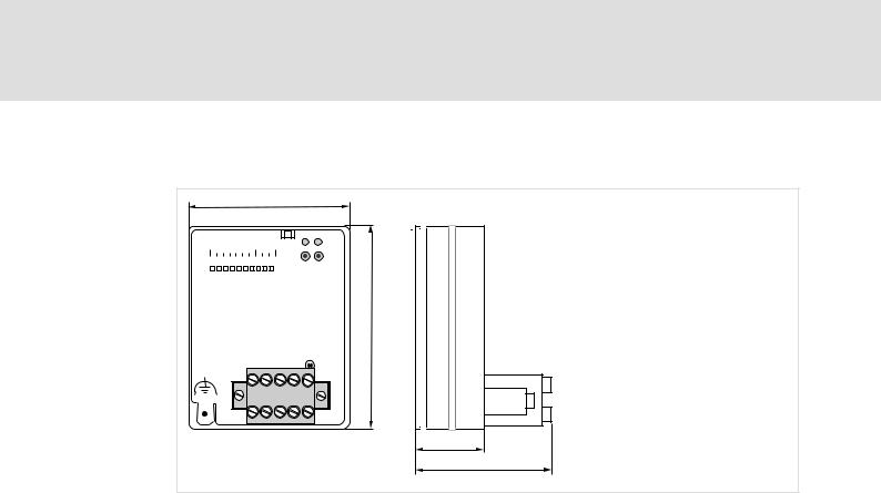
4.4Dimensions
62
Address Bd
 L
L
CANopen
75
CAN |
CAN |
|
||
GND |
LSHLD |
H |
V+ |
|
_ |
|
_ |
||
2178
18 |
36 |
2178CAN003
Fig. 4−1 Dimensions of the communication module (all dimensions in mm)
20 |
l |
EDSMF2178IB EN 3.0
Installation 5
5Installation
}Danger!
Inappropriate handling of the communication module and the standard device can cause serious personal injury and material damage.
Observe the safety instructions and residual hazards described in the documentation for the standard device.
(Stop!
The device contains components that can be destroyed by electrostatic discharge!
Before working on the device, the personnel must ensure that they are free of electrostatic charge by using appropriate measures.
EDSMF2178IB EN 3.0
l |
21 |

5Installation
Mechanical installation
5.1Mechanical installation
2102LEC014
Fig. 5−1 Attaching the communication module
ƒPlug the communication module onto the standard device (here: 8200 vector).
ƒTighten the communication module to the standard device using the fixing screw in order to ensure a good PE connection.
)Note!
For the internal supply of the communication module by the 8200 vector frequency inverter the jumper has to be adjusted within the interface opening (see illustration above).
Observe the notes (¶ 30).
22 |
l |
EDSMF2178IB EN 3.0

Installation 5
Electrical installation
Wiring according to EMC (CE−typical drive system)
5.2Electrical installation
5.2.1Wiring according to EMC (CE−typical drive system)
For wiring according to EMC requirements observe the following points:
)Note!
ƒSeparate control cables/data lines from motor cables.
ƒConnect the shields of control cables/data lines at both ends in the case of digital signals.
ƒUse an equalizing conductor with a cross−section of at least 16 mm2 (reference: PE) to avoid potential differences between the bus nodes.
ƒObserve the other notes concerning EMC−compliant wiring given in the documentation for the standard device.
Procedure for wiring
1.Observe the bus topology, i.e. do not use stubs.
2.Observe notes and wiring instructions in the documents for the control system.
3.Only use cables corresponding to the listed specifications (¶ 26).
4.Observe the permissible bus cable length (¶ 27).
5.Connect bus terminating resistors of 120 W each (scope of supply):
–only to the physically first and last node
–between the terminals CAN−LOW and CAN−HIGH
EDSMF2178IB EN 3.0
l |
23 |

5Installation
Electrical installation
Wiring with a host (master)
5.2.2Wiring with a host (master)
{Danger!
An additional electrical isolation is required if a safe electrical isolation (reinforced insulation) to EN 61800−5−1 is necessary.
For this purpose for instance an interface module for the master computer with an additional electrical isolation can be used (see respective manufacturer information).
For wiring observe the electrical isolation of the supply voltage. The supply voltage is on the same potential as the data bus.
The 5−pole plug connector with double screw connection serves to
ƒconnect the bus (¶ 25);
ƒeffect the external voltage supply (¶ 30).
CAN |
CAN |
|
||
GND |
LSHLD |
H |
V+ |
|
_ |
|
_ |
||
120 

2178CAN003
Fig. 5−2 |
5−pole plug connector with double screw connection |
|
|
|
|
|
|
Designation |
|
Explanation |
|
GND |
|
Reference potential for external voltage supply |
|
|
|
CAN−GND connection |
|
|
|
|
|
CAN_L |
|
Data line / input for terminating resistor 120 W |
|
|
|
|
|
SHIELD |
|
Shielding |
|
|
|
|
|
CAN_H |
|
Data line / input for terminating resistor 120 W |
|
|
|
|
|
V+ |
|
External voltage supply |
|
24 |
l |
EDSMF2178IB EN 3.0

Installation 5
Electrical installation
Wiring system bus (CAN)
5.2.3Wiring system bus (CAN)
Structure of a CAN bus system (example)
The CAN bus system is designed as a 2 conductor (twisted pair) shielded with additional mass and termination at both ends of the line.
For sending and receiving data the following paths are available:
ƒMax. three process data channels (PDO = Process Data Object)
–Process data are sent via the process data channel and are used for high−speed and high−priority control tasks. Typical process data are, for instance, control words, status words, setpoints and actual values of a standard device.
ƒTwo parameter data channels (SDO = Service Data Object)
–The parameters are transferred at lower priority than the process data and are set or changed e.g. during commissioning or product change.
–The parameters are accessed via the parameter data channels of the EMF2178IB communication module to the codes of the basic Lenze device or the corresponding CANopen objects.
–With both parameter data channels, two masters can be connected to a standard device. A PC (e.g. with the Lenze software "Global Drive Control") or an operator terminal serve to change parameters directly at the standard device during operation of a system connected to PLC. The second parameter data channel can be reached under the set address (via DIP switch or C0009) with an offset of "64". If, e.g., a PLC addresses the standard device with the address "1" and a second commanding device the address "65", always the same standard device is addressed.
–The second parameter channel is deactivated in the default state.
)Note!
ƒThe last telegram determines the parameter when a parameter is accessed by two units (see CANopen objects 1200 and 1201 "Server SDO Parameters".(¶ 107)).
ƒPlease observe the notes in the chapter 6Commissioning (¶ 33), if you do not select the baud rate and address via the front DIP switches.
EDSMF2178IB EN 3.0
l |
25 |

5Installation
Electrical installation
Specification of the transmission cable
CAN
GND LOW |
HIGH |
||||
|
|
|
|
|
|
|
|
|
|
|
|
|
|
|
|
|
|
|
|
|
|
|
|
|
|
|
|
|
|
|
|
120 |
|
|
|
|
|
|
|
|
|
|
|
|
|
|
|
Fig. 5−3
GND CAN L |
SHLD CAN H |
V+ |
EMF2178IB
GND
120
2178CAN002
Connection to the plug connector
5.2.4Specification of the transmission cable
We recommend the use of CAN cables in accordance with ISO 11898−2:
CAN cable in accordance with ISO 11898−2
Cable type |
Paired with shielding |
|
|
|
|
Impedance |
120 W (95 ... 140 W) |
|
|
|
|
Cable resistance/cross−section |
|
|
|
|
|
|
Cable length £ 300 m |
£ 70 mW/m / 0.25 … 0.34 mm2 (AWG22) |
|
Cable length 301 … 1000 m |
£ 40 mW/m / 0.5 mm2 (AWG20) |
Signal propagation delay |
£ 5 ns/m |
|
26 |
l |
EDSMF2178IB EN 3.0

Installation 5
Electrical installation
Bus cable length
5.2.5Bus cable length
)Note!
ƒIt is absolutely necessary to comply with the permissible cable lengths.
ƒIf the total cable lengths of the CAN nodes differ for the same baud rate, the smaller value must be used to determine the max. cable length.
ƒObserve the reduction of the total cable length due to the signal delay of the repeater.
5.2.5.1Total cable length
The baud rate determines the total cable length.
Baud rate [kbps] |
Max. bus length [m] |
|
10 |
|
7450 |
|
|
|
20 |
|
3950 |
|
|
|
50 |
|
1550 |
|
|
|
125 |
|
630 |
|
|
|
250 |
|
290 |
|
|
|
500 |
|
120 |
|
|
|
1000 |
|
25 |
Tab. 5−1 |
Total cable length |
|
EDSMF2178IB EN 3.0
l |
27 |

5Installation
Electrical installation
Bus cable length
5.2.5.2Segment cable length
The segment cable length is determined by the cable cross−section used and by the number of nodes. Repeaters divide the total cable length into segments. If no repeaters are used, the segment cable length is identical to the total cable length.
Max. number of |
Cable cross−section |
|
|
|
nodes per segment |
(can be interpolated) |
|
|
|
|
0.25 mm2 |
0.5 mm2 |
0.75 mm2 |
1.0 mm2 |
|
(AWG24) |
(AWG21) |
(AWG19) |
(AWG18) |
2 |
240 m |
430 m |
650 m |
940 m |
|
|
|
|
|
5 |
230 m |
420 m |
640 m |
920 m |
|
|
|
|
|
10 |
230 m |
410 m |
620 m |
900 m |
|
|
|
|
|
20 |
210 m |
390 m |
580 m |
850 m |
|
|
|
|
|
32 |
200 m |
360 m |
550 m |
800 m |
|
|
|
|
|
63 |
170 m |
310 m |
470 m |
690 m |
|
|
|
|
|
100 |
150 m |
270 m |
410 m |
600 m |
|
|
|
|
|
Tab. 5−2 Segment cable length |
|
|
|
|
Example: Selection help
Given
Total cable length to be implemented |
200 m |
|
|
|
|
Number of nodes |
63 |
|
|
|
|
Results |
|
|
Max. possible baud rate |
250 kbps |
|
|
(derived from Tab. 5−1 Total cable length) |
|
|
|
|
Required cable cross−section (interpolated) |
0.30 mm2 (AWG23) |
|
|
(derived from Tab. 5−2 Segment cable length) |
|
|
|
|
Cable cross−section of standard CAN cable |
0.34 mm2 (AWG22) |
|
|
(see specification of the transmission cable ^ 26) |
|
28 |
l |
EDSMF2178IB EN 3.0

Installation 5
Electrical installation
Bus cable length
5.2.5.3Checking the use of repeaters
Compare the values derived fromTab. 5−1 Total cable length (¶ 27) and Tab. 5−2 Segment cable length (¶ 28).
ƒIf the sum of the segment cable lengths is smaller than the total cable length to be implemented, either repeaters must be used or the cable cross−section must be increased.
ƒIf the use of repeaters reduces the max. possible total cable length so much that it is smaller than the total cable length to be implemented, then the cable cross−section must be increased or less repeaters must be used or the baud rate must be decreased.
ƒThe use of a further repeater is recommended as ...
–service interface
Advantage: Trouble−free connection during bus operation is possible.
–calibration interface
Advantage: The calibration/programming unit remains electrically isolated.
Example
Given
Total cable length to be implemented |
450 m |
|
|
|
|
Number of nodes |
32 |
|
|
|
|
Cable cross−section |
0.50 mm2 (AWG 20) |
|
Baud rate |
125 kbps |
|
|
|
|
Repeater used |
Lenze repeater EMF2176IB |
|
|
|
|
Reduction of the max. total cable length per |
30 m |
|
repeater (EMF2176IB) |
|
|
|
|
|
Results |
|
|
Max. total cable length |
630 m |
|
|
(see Tab. 5−1 Total cable length (^ 27)) |
|
Max. segment cable length |
360 m |
|
|
(see Tab. 5−2 Segment cable length (^ 28)) |
|
|
|
|
Comparison |
The max. segment cable length is smaller than the total cable |
|
|
length to be implemented. |
|
|
|
|
Conclusion |
A repeater must be installed at the determined max. segment |
|
|
cable length of 360 m. |
|
|
|
|
Results with 1 repeater |
|
|
Max. total cable length |
600 m |
|
|
(Reduction of the total cable length (^ 27) by 30 m) |
|
Max. segment cable length |
720 m |
|
|
|
|
Comparison |
Both the possible total cable length and the segment cable lengths |
|
|
are larger than the total cable length to be implemented. |
|
|
|
|
Conclusion |
1 repeater is sufficient to implement the total cable length of 450 |
|
|
m. |
|
|
|
|
EDSMF2178IB EN 3.0
l |
29 |
5Installation
Electrical installation
Voltage supply
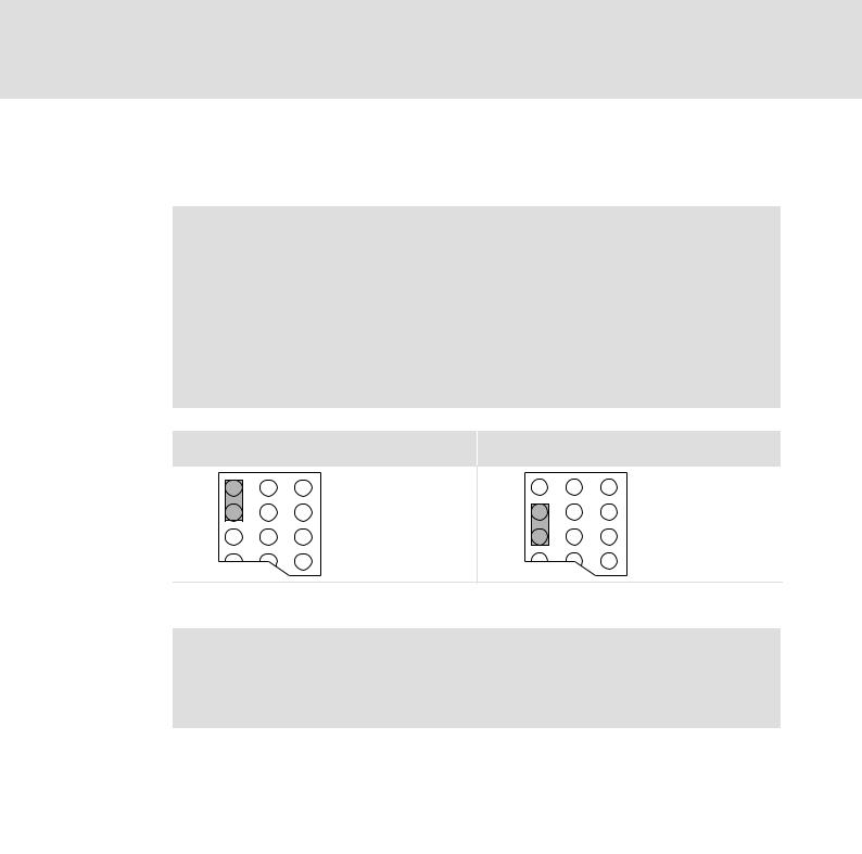
5.2.6Voltage supply Internal voltage supply
)Note!
Internal voltage supply has been selected in the case of standard devices with an extended AIF interface opening (e.g. front of 8200 vector). The area shown on a grey background in the graphic marks the jumper position.
ƒBy default, this is not supplied internally in the standard device.
ƒFor internal voltage supply place the jumper on the position indicated below.
In the case of all other device series (9300, ECS), voltage is always supplied from the standard device.
Lenze setting |
Internal voltage supply |
(Only external voltage supply possible.)
External voltage supply
)Note!
In the case of an external voltage supply and for greater distances between the control cabinets, always use a separate power supply unit (SELV/PELV) that is safely separated in accordance with EN 61800−5−1 in each control cabinet.
The external voltage supply of the communication module ...
ƒis required if communication via the fieldbus is to be continued in case the supply of the standard device fails.
ƒis carried out via the 2−pole plug connector with screw connection (24 V DC):
Terminal |
Description |
|
V+ |
External voltage supply |
|
|
V = 24 V DC ± 10 % |
|
|
I = 100 mA |
|
|
|
|
GND |
Reference potential for external voltage supply |
|
ƒ The parameters of a basic device disconnected from the mains cannot be accessed.
30 |
l |
EDSMF2178IB EN 3.0
Loading...