


 Loading...
9400
Servo Drives 9400 HighLine_ _ _ _ _ _ _ _ _ _ _
E94AxHExxxx
Reference manual |
EN |
|
|
Ä.MvGä 13448538
L
Overview of technical documentation for Servo Drives 9400
_ _ _ _ _ _ _ _ _ _ _ _ _ _ _ _ _ _ _ _ _ _ _ _ _ _ _ _ _ _ _ _ _ _ _ _ _ _ _ _ _ _ _ _ _ _ _ _ _ _ _ _ _ _ _ _ _ _ _ _ _ _ _ _
Project planning, selection & order
Hardware manual 9400
Catalogue / electronic catalogue (DSC - Drive Solution Catalogue)
Mounting & wiring
MA - 9400 StateLine/HighLine
MA - communication module
MA - extension module
MA - safety module
MA - accessories
MA - remote maintenance components
Parameter setting
BA - keypad
SW - Lenze software »Engineer«
SW - controller (9400 StateLine/HighLine/PLC)
SW - regenerative power supply module
KHB - communication module
SW - extension module
SW - safety module
SW - Lenze technology application
SW - function library 9400
Configuring & programming
SW - Lenze software »Engineer«
SW - Lenze software »PLC Designer«
SW - controller (9400 HighLine/PLC)
KHB - communication module
SW - extension module
SW - safety module
SW - Lenze technology application
SW - function library 9400
Drive commissioning
Commissioning guide
SW - controller (9400 StateLine/HighLine/PLC)
Chapter "Commissioning" ( 22)
Chapter "Oscilloscope" ( 579)
Chapter "Diagnostics & fault analysis" ( 598)
Remote maintenance manual
Networking structure
KHB - communication medium used
Legend:
Printed documentation
Online documentation (PDF/Engineer online help)
Abbreviations used:
BA Operating instructions
KHB Communication manual
MA Mounting instructions
SW Software Manual
This documentation
This documentation
This documentation
2 |
Lenze · Servo-Inverter 9400 HighLine · Reference manual · DMS 10.0 EN · 11/2013 · TD05/06 |
Contents
_ _ _ _ _ _ _ _ _ _ _ _ _ _ _ _ _ _ _ _ _ _ _ _ _ _ _ _ _ _ _ _ _ _ _ _ _ _ _ _ _ _ _ _ _ _ _ _ _ _ _ _ _ _ _ _ _ _ _ _ _ _ _ _
1 |
About this documentation _ _ _ _ _ _ _ _ _ _ _ _ _ _ _ _ _ _ _ _ _ _ _ _ _ _ _ _ _ _ _ _ _ _ _ _ _ _ _ |
11 |
||||||||
1.1 |
Conventions used |
_ _ _ _ _ _ _ _ _ _ _ _ _ _ _ _ _ _ _ _ _ _ _ _ _ _ _ _ _ _ _ _ _ _ _ _ _ _ _ _ _ _ _ _ |
12 |
|||||||
1.2 |
Terminology used |
_ _ _ _ _ _ _ _ _ _ _ _ _ _ _ _ _ _ _ _ _ _ _ _ _ _ _ _ _ _ _ _ _ _ _ _ _ _ _ _ _ _ _ _ |
13 |
|||||||
1.3 |
Definition of notes used _ _ _ _ _ _ _ _ _ _ _ _ _ _ _ _ _ _ _ _ _ _ _ _ _ _ _ _ _ _ _ _ _ _ _ _ _ _ _ _ _ |
14 |
||||||||
2 |
Introduction _ _ _ _ _ _ _ _ _ _ _ _ _ _ _ _ _ _ _ _ _ _ _ _ _ _ _ _ _ _ _ _ _ _ _ _ _ _ _ _ _ _ _ _ _ _ _ |
15 |
||||||||
2.1 |
Parameter setting, configuring, or programming? |
_ _ _ _ _ _ _ _ _ _ _ _ _ _ _ _ _ _ _ _ _ _ _ _ _ _ |
15 |
|||||||
|
2.1.1 |
Basic functionalities _ _ _ _ _ _ _ _ _ _ _ _ _ _ _ _ _ _ _ _ _ _ _ _ _ _ _ _ _ _ _ _ _ _ _ _ _ _ |
16 |
|||||||
|
2.1.2 |
Technology applications _ _ _ _ _ _ _ _ _ _ _ _ _ _ _ _ _ _ _ _ _ _ _ _ _ _ _ _ _ _ _ _ _ _ _ _ |
16 |
|||||||
2.2 |
Communicating with the controller _ _ _ _ _ _ _ _ _ _ _ _ _ _ _ _ _ _ _ _ _ _ _ _ _ _ _ _ _ _ _ _ _ _ |
17 |
||||||||
|
2.2.1 |
Going online via diagnostic adapter |
_ _ _ _ _ _ _ _ _ _ _ _ _ _ _ _ _ _ _ _ _ _ _ _ _ _ _ _ _ |
17 |
||||||
|
2.2.2 |
Going online via system bus (CAN on board) _ _ _ _ _ _ _ _ _ _ _ _ _ _ _ _ _ _ _ _ _ _ _ _ _ |
20 |
|||||||
|
2.2.3 |
Use of other communication interfaces |
_ _ _ _ _ _ _ _ _ _ _ _ _ _ _ _ _ _ _ _ _ _ _ _ _ _ _ |
20 |
||||||
2.3 |
Signal types & scaling _ _ _ _ _ _ _ _ _ _ _ _ _ _ _ _ _ _ _ _ _ _ _ _ _ _ _ _ _ _ _ _ _ _ _ _ _ _ _ _ _ _ |
21 |
||||||||
3 |
Commissioning |
_ _ _ _ _ _ _ _ _ _ _ _ _ _ _ _ _ _ _ _ _ _ _ _ _ _ _ _ _ _ _ _ _ _ _ _ _ _ _ _ _ _ _ _ _ |
22 |
|||||||
3.1 |
General information _ _ _ _ _ _ _ _ _ _ _ _ _ _ _ _ _ _ _ _ _ _ _ _ _ _ _ _ _ _ _ _ _ _ _ _ _ _ _ _ _ _ _ |
23 |
||||||||
3.2 |
Notes on commissioning using the keypad |
_ _ _ _ _ _ _ _ _ _ _ _ _ _ _ _ _ _ _ _ _ _ _ _ _ _ _ _ _ _ |
24 |
|||||||
3.3 |
Initial commissioning _ _ _ _ _ _ _ _ _ _ _ _ _ _ _ _ _ _ _ _ _ _ _ _ _ _ _ _ _ _ _ _ _ _ _ _ _ _ _ _ _ _ |
25 |
||||||||
3.4 |
Standard set-up |
_ _ _ _ _ _ _ _ _ _ _ _ _ _ _ _ _ _ _ _ _ _ _ _ _ _ _ _ _ _ _ _ _ _ _ _ _ _ _ _ _ _ _ _ _ |
26 |
|||||||
3.5 |
Controller replacement |
_ _ _ _ _ _ _ _ _ _ _ _ _ _ _ _ _ _ _ _ _ _ _ _ _ _ _ _ _ _ _ _ _ _ _ _ _ _ _ _ _ |
27 |
|||||||
3.6 |
Motor replacement |
_ _ _ _ _ _ _ _ _ _ _ _ _ _ _ _ _ _ _ _ _ _ _ _ _ _ _ _ _ _ _ _ _ _ _ _ _ _ _ _ _ _ _ |
27 |
|||||||
4 |
Drive interface _ _ _ _ _ _ _ _ _ _ _ _ _ _ _ _ _ _ _ _ _ _ _ _ _ _ _ _ _ _ _ _ _ _ _ _ _ _ _ _ _ _ _ _ _ _ |
28 |
||||||||
4.1 |
Machine parameters |
_ _ _ _ _ _ _ _ _ _ _ _ _ _ _ _ _ _ _ _ _ _ _ _ _ _ _ _ _ _ _ _ _ _ _ _ _ _ _ _ _ _ |
29 |
|||||||
|
4.1.1 |
Mains voltage |
_ _ _ _ _ _ _ _ _ _ _ _ _ _ _ _ _ _ _ _ _ _ _ _ _ _ _ _ _ _ _ _ _ _ _ _ _ _ _ _ _ |
30 |
||||||
|
4.1.2 |
Gearbox ratio _ _ _ _ _ _ _ _ _ _ _ _ _ _ _ _ _ _ _ _ _ _ _ _ _ _ _ _ _ _ _ _ _ _ _ _ _ _ _ _ _ _ |
31 |
|||||||
|
4.1.3 |
Motor mounting direction _ _ _ _ _ _ _ _ _ _ _ _ _ _ _ _ _ _ _ _ _ _ _ _ _ _ _ _ _ _ _ _ _ _ _ |
32 |
|||||||
|
4.1.4 |
Feedback configuration _ _ _ _ _ _ _ _ _ _ _ _ _ _ _ _ _ _ _ _ _ _ _ _ _ _ _ _ _ _ _ _ _ _ _ _ |
32 |
|||||||
|
4.1.5 |
Unit/user-defined unit _ _ _ _ _ _ _ _ _ _ _ _ _ _ _ _ _ _ _ _ _ _ _ _ _ _ _ _ _ _ _ _ _ _ _ _ _ |
33 |
|||||||
|
4.1.6 |
Traversing range _ _ _ _ _ _ _ _ _ _ _ _ _ _ _ _ _ _ _ _ _ _ _ _ _ _ _ _ _ _ _ _ _ _ _ _ _ _ _ _ |
34 |
|||||||
|
4.1.7 |
Feed constant |
_ _ _ _ _ _ _ _ _ _ _ _ _ _ _ _ _ _ _ _ _ _ _ _ _ _ _ _ _ _ _ _ _ _ _ _ _ _ _ _ _ |
36 |
||||||
|
4.1.8 |
Resolution of an encoder revolution |
_ _ _ _ _ _ _ _ _ _ _ _ _ _ _ _ _ _ _ _ _ _ _ _ _ _ _ _ _ |
37 |
||||||
|
4.1.9 |
Max. position, speed, and acceleration that can be displayed internally _ _ _ _ _ _ _ _ _ _ |
40 |
|||||||
4.2 |
Device commands _ _ _ _ _ _ _ _ _ _ _ _ _ _ _ _ _ _ _ _ _ _ _ _ _ _ _ _ _ _ _ _ _ _ _ _ _ _ _ _ _ _ _ _ |
42 |
||||||||
|
4.2.1 |
Load Lenze setting _ _ _ _ _ _ _ _ _ _ _ _ _ _ _ _ _ _ _ _ _ _ _ _ _ _ _ _ _ _ _ _ _ _ _ _ _ _ _ |
44 |
|||||||
|
4.2.2 |
Load start parameters _ _ _ _ _ _ _ _ _ _ _ _ _ _ _ _ _ _ _ _ _ _ _ _ _ _ _ _ _ _ _ _ _ _ _ _ _ |
45 |
|||||||
|
4.2.3 |
ENP:Load plant data _ _ _ _ _ _ _ _ _ _ _ _ _ _ _ _ _ _ _ _ _ _ _ _ _ _ _ _ _ _ _ _ _ _ _ _ _ _ |
46 |
|||||||
|
4.2.4 |
Activate application _ _ _ _ _ _ _ _ _ _ _ _ _ _ _ _ _ _ _ _ _ _ _ _ _ _ _ _ _ _ _ _ _ _ _ _ _ _ |
47 |
|||||||
|
4.2.5 |
Save selected application _ _ _ _ _ _ _ _ _ _ _ _ _ _ _ _ _ _ _ _ _ _ _ _ _ _ _ _ _ _ _ _ _ _ _ |
48 |
|||||||
|
4.2.6 |
Save start parameters _ _ _ _ _ _ _ _ _ _ _ _ _ _ _ _ _ _ _ _ _ _ _ _ _ _ _ _ _ _ _ _ _ _ _ _ _ |
49 |
|||||||
|
4.2.7 |
Delete logbook _ _ _ _ _ _ _ _ _ _ _ _ _ _ _ _ _ _ _ _ _ _ _ _ _ _ _ _ _ _ _ _ _ _ _ _ _ _ _ _ _ |
51 |
|||||||
|
4.2.8 |
Archive logbook |
|
_ _ _ _ _ _ _ _ _ _ _ _ _ _ _ _ _ _ _ _ _ _ _ _ _ _ _ _ _ _ _ _ _ _ _ _ _ _ _ _ |
52 |
|||||
|
4.2.9 |
Start application |
_ _ _ _ _ _ _ _ _ _ _ _ _ _ _ _ _ _ _ _ _ _ _ _ _ _ _ _ _ _ _ _ _ _ _ _ _ _ _ _ |
53 |
||||||
|
4.2.10 |
Stop application |
_ _ _ _ _ _ _ _ _ _ _ _ _ _ _ _ _ _ _ _ _ _ _ _ _ _ _ _ _ _ _ _ _ _ _ _ _ _ _ _ |
54 |
||||||
|
4.2.11 |
Reset program |
_ _ _ _ _ _ _ _ _ _ _ _ _ _ _ _ _ _ _ _ _ _ _ _ _ _ _ _ _ _ _ _ _ _ _ _ _ _ _ _ _ |
55 |
||||||
|
4.2.12 |
Delete program |
|
_ _ _ _ _ _ _ _ _ _ _ _ _ _ _ _ _ _ _ _ _ _ _ _ _ _ _ _ _ _ _ _ _ _ _ _ _ _ _ _ |
56 |
|||||
|
4.2.13 |
Restart program |
_ _ _ _ _ _ _ _ _ _ _ _ _ _ _ _ _ _ _ _ _ _ _ _ _ _ _ _ _ _ _ _ _ _ _ _ _ _ _ _ |
57 |
||||||
|
4.2.14 |
Reset runtime measurement _ _ _ _ _ _ _ _ _ _ _ _ _ _ _ _ _ _ _ _ _ _ _ _ _ _ _ _ _ _ _ _ _ |
58 |
|||||||
|
4.2.15 |
Inhibit controller _ _ _ _ _ _ _ _ _ _ _ _ _ _ _ _ _ _ _ _ _ _ _ _ _ _ _ _ _ _ _ _ _ _ _ _ _ _ _ _ |
60 |
|||||||
|
4.2.16 |
Enable controller _ _ _ _ _ _ _ _ _ _ _ _ _ _ _ _ _ _ _ _ _ _ _ _ _ _ _ _ _ _ _ _ _ _ _ _ _ _ _ _ |
61 |
|||||||
|
4.2.17 |
Reset error |
|
_ _ _ _ _ _ _ _ _ _ _ _ _ _ _ _ _ _ _ _ _ _ _ _ _ _ _ _ _ _ _ _ _ _ _ _ _ _ _ _ _ _ _ |
62 |
|||||
|
4.2.18 |
Activate quick stop _ _ _ _ _ _ _ _ _ _ _ _ _ _ _ _ _ _ _ _ _ _ _ _ _ _ _ _ _ _ _ _ _ _ _ _ _ _ _ |
63 |
|||||||
|
4.2.19 |
Reset quick stop |
_ _ _ _ _ _ _ _ _ _ _ _ _ _ _ _ _ _ _ _ _ _ _ _ _ _ _ _ _ _ _ _ _ _ _ _ _ _ _ _ |
64 |
||||||
Lenze · Servo-Inverter 9400 HighLine · Reference manual · DMS 10.0 EN · 11/2013 · TD05/06 |
3 |
Contents
_ _ _ _ _ _ _ _ _ _ _ _ _ _ _ _ _ _ _ _ _ _ _ _ _ _ _ _ _ _ _ _ _ _ _ _ _ _ _ _ _ _ _ _ _ _ _ _ _ _ _ _ _ _ _ _ _ _ _ _ _ _ _ _
|
4.2.20 |
Identify pole position (360°) _ _ _ _ _ _ _ _ _ _ _ _ _ _ _ _ _ _ _ _ _ _ _ _ _ _ _ _ _ _ _ _ _ _ |
65 |
||||||||
|
4.2.21 |
Identify pole position (min. motion) |
_ _ _ _ _ _ _ _ _ _ _ _ _ _ _ _ _ _ _ _ _ _ _ _ _ _ _ _ _ |
66 |
|||||||
|
4.2.22 |
Resolver error identification _ _ _ _ _ _ _ _ _ _ _ _ _ _ _ _ _ _ _ _ _ _ _ _ _ _ _ _ _ _ _ _ _ _ |
68 |
||||||||
|
4.2.23 |
Load Lenze INV characteristic |
_ _ _ _ _ _ _ _ _ _ _ _ _ _ _ _ _ _ _ _ _ _ _ _ _ _ _ _ _ _ _ _ _ |
69 |
|||||||
|
4.2.24 |
Calculate inv. characteristic |
_ _ _ _ _ _ _ _ _ _ _ _ _ _ _ _ _ _ _ _ _ _ _ _ _ _ _ _ _ _ _ _ _ _ |
70 |
|||||||
|
4.2.25 |
Determine motor parameters _ _ _ _ _ _ _ _ _ _ _ _ _ _ _ _ _ _ _ _ _ _ _ _ _ _ _ _ _ _ _ _ _ |
71 |
||||||||
|
4.2.26 |
Calculate current controller parameters _ _ _ _ _ _ _ _ _ _ _ _ _ _ _ _ _ _ _ _ _ _ _ _ _ _ _ |
72 |
||||||||
|
4.2.27 |
Calculate speed controller parameters _ _ _ _ _ _ _ _ _ _ _ _ _ _ _ _ _ _ _ _ _ _ _ _ _ _ _ _ |
74 |
||||||||
|
4.2.28 |
CAN on board: Reset Node |
|
_ _ _ _ _ _ _ _ _ _ _ _ _ _ _ _ _ _ _ _ _ _ _ _ _ _ _ _ _ _ _ _ _ _ |
75 |
||||||
|
4.2.29 |
CAN module: Reset node |
_ _ _ _ _ _ _ _ _ _ _ _ _ _ _ _ _ _ _ _ _ _ _ _ _ _ _ _ _ _ _ _ _ _ _ |
76 |
|||||||
|
4.2.30 |
CAN on board: Pred.Connect.Set |
_ _ _ _ _ _ _ _ _ _ _ _ _ _ _ _ _ _ _ _ _ _ _ _ _ _ _ _ _ _ _ |
77 |
|||||||
|
4.2.31 |
CAN module: Pred.Connect.Set |
_ _ _ _ _ _ _ _ _ _ _ _ _ _ _ _ _ _ _ _ _ _ _ _ _ _ _ _ _ _ _ _ |
78 |
|||||||
|
4.2.32 |
CAN on board: Identify node |
|
_ _ _ _ _ _ _ _ _ _ _ _ _ _ _ _ _ _ _ _ _ _ _ _ _ _ _ _ _ _ _ _ _ |
79 |
||||||
|
4.2.33 |
CAN module: Identify node |
_ _ _ _ _ _ _ _ _ _ _ _ _ _ _ _ _ _ _ _ _ _ _ _ _ _ _ _ _ _ _ _ _ _ |
80 |
|||||||
|
4.2.34 |
Unbind/bind Ethernet module MXI1 _ _ _ _ _ _ _ _ _ _ _ _ _ _ _ _ _ _ _ _ _ _ _ _ _ _ _ _ _ |
81 |
||||||||
|
4.2.35 |
Unbind/bind Ethernet module MXI2 _ _ _ _ _ _ _ _ _ _ _ _ _ _ _ _ _ _ _ _ _ _ _ _ _ _ _ _ _ |
82 |
||||||||
|
4.2.36 |
Activate parameter set 1 ... 4 _ _ _ _ _ _ _ _ _ _ _ _ _ _ _ _ _ _ _ _ _ _ _ _ _ _ _ _ _ _ _ _ _ |
83 |
||||||||
|
4.2.37 |
Activate parameter set 1 ... 4 _ _ _ _ _ _ _ _ _ _ _ _ _ _ _ _ _ _ _ _ _ _ _ _ _ _ _ _ _ _ _ _ _ |
85 |
||||||||
|
4.2.38 |
Load cam data |
_ _ _ _ _ _ _ _ _ _ _ _ _ _ _ _ _ _ _ _ _ _ _ _ _ _ _ _ _ _ _ _ _ _ _ _ _ _ _ _ _ |
87 |
|||||||
|
4.2.39 |
Save cam data |
_ _ _ _ _ _ _ _ _ _ _ _ _ _ _ _ _ _ _ _ _ _ _ _ _ _ _ _ _ _ _ _ _ _ _ _ _ _ _ _ _ |
89 |
|||||||
|
4.2.40 |
Calculate cam data _ _ _ _ _ _ _ _ _ _ _ _ _ _ _ _ _ _ _ _ _ _ _ _ _ _ _ _ _ _ _ _ _ _ _ _ _ _ _ |
91 |
||||||||
|
4.2.41 |
Calculate cam data checksum _ _ _ _ _ _ _ _ _ _ _ _ _ _ _ _ _ _ _ _ _ _ _ _ _ _ _ _ _ _ _ _ _ |
92 |
||||||||
|
4.2.42 |
Format file system _ _ _ _ _ _ _ _ _ _ _ _ _ _ _ _ _ _ _ _ _ _ _ _ _ _ _ _ _ _ _ _ _ _ _ _ _ _ _ |
93 |
||||||||
|
4.2.43 |
Restore file system _ _ _ _ _ _ _ _ _ _ _ _ _ _ _ _ _ _ _ _ _ _ _ _ _ _ _ _ _ _ _ _ _ _ _ _ _ _ _ |
94 |
||||||||
|
4.2.44 |
Prepare firmware update |
_ _ _ _ _ _ _ _ _ _ _ _ _ _ _ _ _ _ _ _ _ _ _ _ _ _ _ _ _ _ _ _ _ _ _ |
95 |
|||||||
|
4.2.45 |
Restart controller _ _ _ _ _ _ _ _ _ _ _ _ _ _ _ _ _ _ _ _ _ _ _ _ _ _ _ _ _ _ _ _ _ _ _ _ _ _ _ _ |
96 |
||||||||
4.3 |
Device states _ _ _ _ _ _ _ _ _ _ _ _ _ _ _ _ _ _ _ _ _ _ _ _ _ _ _ _ _ _ _ _ _ _ _ _ _ _ _ _ _ _ _ _ _ _ _ |
97 |
|||||||||
|
4.3.1 |
"Initialisation active" state |
|
_ _ _ _ _ _ _ _ _ _ _ _ _ _ _ _ _ _ _ _ _ _ _ _ _ _ _ _ _ _ _ _ _ _ |
99 |
||||||
|
4.3.2 |
"Safe torque off active" state |
_ _ _ _ _ _ _ _ _ _ _ _ _ _ _ _ _ _ _ _ _ _ _ _ _ _ _ _ _ _ _ _ _ |
100 |
|||||||
|
4.3.3 |
"Device is ready to switch on" state _ _ _ _ _ _ _ _ _ _ _ _ _ _ _ _ _ _ _ _ _ _ _ _ _ _ _ _ _ _ |
100 |
||||||||
|
4.3.4 |
"Device is switched on" state |
_ _ _ _ _ _ _ _ _ _ _ _ _ _ _ _ _ _ _ _ _ _ _ _ _ _ _ _ _ _ _ _ _ |
101 |
|||||||
|
4.3.5 |
"Operation" state _ _ _ _ _ _ _ _ _ _ _ _ _ _ _ _ _ _ _ _ _ _ _ _ _ _ _ _ _ _ _ _ _ _ _ _ _ _ _ _ |
101 |
||||||||
|
4.3.6 |
"Warning active" _ _ _ _ _ _ _ _ _ _ _ _ _ _ _ _ _ _ _ _ _ _ _ _ _ _ _ _ _ _ _ _ _ _ _ _ _ _ _ _ |
102 |
||||||||
|
4.3.7 |
"Warning locked active" _ _ _ _ _ _ _ _ _ _ _ _ _ _ _ _ _ _ _ _ _ _ _ _ _ _ _ _ _ _ _ _ _ _ _ _ |
102 |
||||||||
|
4.3.8 |
"Quick stop by trouble active" state _ _ _ _ _ _ _ _ _ _ _ _ _ _ _ _ _ _ _ _ _ _ _ _ _ _ _ _ _ _ |
102 |
||||||||
|
4.3.9 |
"Trouble active" state |
_ _ _ _ _ _ _ _ _ _ _ _ _ _ _ _ _ _ _ _ _ _ _ _ _ _ _ _ _ _ _ _ _ _ _ _ _ |
103 |
|||||||
|
4.3.10 |
"Fault active" state _ _ _ _ _ _ _ _ _ _ _ _ _ _ _ _ _ _ _ _ _ _ _ _ _ _ _ _ _ _ _ _ _ _ _ _ _ _ _ |
103 |
||||||||
|
4.3.11 |
"System fault active" state |
|
_ _ _ _ _ _ _ _ _ _ _ _ _ _ _ _ _ _ _ _ _ _ _ _ _ _ _ _ _ _ _ _ _ _ |
103 |
||||||
4.4 Automatic restart after mains connection/trouble... |
_ _ _ _ _ _ _ _ _ _ _ _ _ _ _ _ _ _ _ _ _ _ _ _ _ |
104 |
|||||||||
4.5 Behaviour after task overflow |
_ _ _ _ _ _ _ _ _ _ _ _ _ _ _ _ _ _ _ _ _ _ _ _ _ _ _ _ _ _ _ _ _ _ _ _ _ |
106 |
|||||||||
4.6 |
Device output power _ _ _ _ _ _ _ _ _ _ _ _ _ _ _ _ _ _ _ _ _ _ _ _ _ _ _ _ _ _ _ _ _ _ _ _ _ _ _ _ _ _ |
107 |
|||||||||
|
4.6.1 |
Switching frequency _ _ _ _ _ _ _ _ _ _ _ _ _ _ _ _ _ _ _ _ _ _ _ _ _ _ _ _ _ _ _ _ _ _ _ _ _ _ |
107 |
||||||||
|
4.6.2 |
Monitoring of the device utilisation |
_ _ _ _ _ _ _ _ _ _ _ _ _ _ _ _ _ _ _ _ _ _ _ _ _ _ _ _ _ |
108 |
|||||||
|
4.6.3 |
Operation with increased continuous power _ _ _ _ _ _ _ _ _ _ _ _ _ _ _ _ _ _ _ _ _ _ _ _ _ |
109 |
||||||||
4.7 Internal interfaces | "LS_DriveInterface" system block |
_ _ _ _ _ _ _ _ _ _ _ _ _ _ _ _ _ _ _ _ _ _ _ _ |
110 |
|||||||||
|
4.7.1 |
Status signals _ _ _ _ _ _ _ _ _ _ _ _ _ _ _ _ _ _ _ _ _ _ _ _ _ _ _ _ _ _ _ _ _ _ _ _ _ _ _ _ _ _ |
113 |
||||||||
|
4.7.2 |
Monitoring of external events |
|
_ _ _ _ _ _ _ _ _ _ _ _ _ _ _ _ _ _ _ _ _ _ _ _ _ _ _ _ _ _ _ _ |
114 |
||||||
4 |
Lenze · Servo-Inverter 9400 HighLine · Reference manual · DMS 10.0 EN · 11/2013 · TD05/06 |
Contents
_ _ _ _ _ _ _ _ _ _ _ _ _ _ _ _ _ _ _ _ _ _ _ _ _ _ _ _ _ _ _ _ _ _ _ _ _ _ _ _ _ _ _ _ _ _ _ _ _ _ _ _ _ _ _ _ _ _ _ _ _ _ _ _
5 |
Motor interface _ _ _ _ _ _ _ _ _ _ _ _ _ _ _ _ _ _ _ _ _ _ _ _ _ _ _ _ _ _ _ _ _ _ _ _ _ _ _ _ _ _ _ _ _ |
115 |
||||||
5.1 |
General information _ _ _ _ _ _ _ _ _ _ _ _ _ _ _ _ _ _ _ _ _ _ _ _ _ _ _ _ _ _ _ _ _ _ _ _ _ _ _ _ _ _ _ |
117 |
||||||
|
5.1.1 |
Reading out motor data from the controller _ _ _ _ _ _ _ _ _ _ _ _ _ _ _ _ _ _ _ _ _ _ _ _ _ |
117 |
|||||
|
5.1.2 |
Selecting a motor from the motor catalogue in the »Engineer« _ _ _ _ _ _ _ _ _ _ _ _ _ _ |
118 |
|||||
|
5.1.3 |
Displaying/editing motor data in »Engineer« _ _ _ _ _ _ _ _ _ _ _ _ _ _ _ _ _ _ _ _ _ _ _ _ |
119 |
|||||
5.2 |
Select motor control _ _ _ _ _ _ _ _ _ _ _ _ _ _ _ _ _ _ _ _ _ _ _ _ _ _ _ _ _ _ _ _ _ _ _ _ _ _ _ _ _ _ _ |
121 |
||||||
5.3 |
Adjusting motor and controller to each other _ _ _ _ _ _ _ _ _ _ _ _ _ _ _ _ _ _ _ _ _ _ _ _ _ _ _ _ _ |
123 |
||||||
|
5.3.1 |
Accepting/adapting plant parameters _ _ _ _ _ _ _ _ _ _ _ _ _ _ _ _ _ _ _ _ _ _ _ _ _ _ _ _ |
124 |
|||||
|
5.3.2 |
Parameterising motor encoder _ _ _ _ _ _ _ _ _ _ _ _ _ _ _ _ _ _ _ _ _ _ _ _ _ _ _ _ _ _ _ _ |
126 |
|||||
|
5.3.3 |
Pole position identification _ _ _ _ _ _ _ _ _ _ _ _ _ _ _ _ _ _ _ _ _ _ _ _ _ _ _ _ _ _ _ _ _ _ |
128 |
|||||
|
5.3.4 |
Optimising the switching performance of the inverter |
_ _ _ _ _ _ _ _ _ _ _ _ _ _ _ _ _ _ _ |
135 |
||||
|
5.3.5 |
Determining the motor parameters |
_ _ _ _ _ _ _ _ _ _ _ _ _ _ _ _ _ _ _ _ _ _ _ _ _ _ _ _ _ |
138 |
||||
5.4 |
Servo control (SC) _ _ _ _ _ _ _ _ _ _ _ _ _ _ _ _ _ _ _ _ _ _ _ _ _ _ _ _ _ _ _ _ _ _ _ _ _ _ _ _ _ _ _ _ |
142 |
||||||
|
5.4.1 |
Optimising the control mode |
_ _ _ _ _ _ _ _ _ _ _ _ _ _ _ _ _ _ _ _ _ _ _ _ _ _ _ _ _ _ _ _ _ |
143 |
||||
|
5.4.2 |
Signal flow (servo control for synchronous motor) _ _ _ _ _ _ _ _ _ _ _ _ _ _ _ _ _ _ _ _ _ |
159 |
|||||
|
5.4.3 |
Signal flow (servo control for asynchronous motor) _ _ _ _ _ _ _ _ _ _ _ _ _ _ _ _ _ _ _ _ _ |
161 |
|||||
5.5 |
Sensorless vector control (SLVC) |
_ _ _ _ _ _ _ _ _ _ _ _ _ _ _ _ _ _ _ _ _ _ _ _ _ _ _ _ _ _ _ _ _ _ _ _ |
163 |
|||||
|
5.5.1 |
Basic settings _ _ _ _ _ _ _ _ _ _ _ _ _ _ _ _ _ _ _ _ _ _ _ _ _ _ _ _ _ _ _ _ _ _ _ _ _ _ _ _ _ _ |
164 |
|||||
|
5.5.2 |
Optimising motor parameters |
_ _ _ _ _ _ _ _ _ _ _ _ _ _ _ _ _ _ _ _ _ _ _ _ _ _ _ _ _ _ _ _ |
166 |
||||
|
5.5.3 |
Optimising the control mode |
_ _ _ _ _ _ _ _ _ _ _ _ _ _ _ _ _ _ _ _ _ _ _ _ _ _ _ _ _ _ _ _ _ |
172 |
||||
|
5.5.4 |
Signal flow |
_ _ _ _ _ _ _ _ _ _ _ _ _ _ _ _ _ _ _ _ _ _ _ _ _ _ _ _ _ _ _ _ _ _ _ _ _ _ _ _ _ _ _ |
180 |
||||
5.6 |
V/f control (VFCplus) |
_ _ _ _ _ _ _ _ _ _ _ _ _ _ _ _ _ _ _ _ _ _ _ _ _ _ _ _ _ _ _ _ _ _ _ _ _ _ _ _ _ _ |
181 |
|||||
|
5.6.1 |
Basic settings _ _ _ _ _ _ _ _ _ _ _ _ _ _ _ _ _ _ _ _ _ _ _ _ _ _ _ _ _ _ _ _ _ _ _ _ _ _ _ _ _ _ |
181 |
|||||
|
5.6.2 |
Optimising the control mode |
_ _ _ _ _ _ _ _ _ _ _ _ _ _ _ _ _ _ _ _ _ _ _ _ _ _ _ _ _ _ _ _ _ |
188 |
||||
|
5.6.3 |
Signal flow |
_ _ _ _ _ _ _ _ _ _ _ _ _ _ _ _ _ _ _ _ _ _ _ _ _ _ _ _ _ _ _ _ _ _ _ _ _ _ _ _ _ _ _ |
196 |
||||
5.7 |
V/f control (VFCplus) |
_ _ _ _ _ _ _ _ _ _ _ _ _ _ _ _ _ _ _ _ _ _ _ _ _ _ _ _ _ _ _ _ _ _ _ _ _ _ _ _ _ _ |
197 |
|||||
|
5.7.1 |
Signal flow |
_ _ _ _ _ _ _ _ _ _ _ _ _ _ _ _ _ _ _ _ _ _ _ _ _ _ _ _ _ _ _ _ _ _ _ _ _ _ _ _ _ _ _ |
198 |
||||
5.8 |
Parameterisable additional functions |
_ _ _ _ _ _ _ _ _ _ _ _ _ _ _ _ _ _ _ _ _ _ _ _ _ _ _ _ _ _ _ _ _ |
200 |
|||||
|
5.8.1 |
Correction of the stator leakage inductance... _ _ _ _ _ _ _ _ _ _ _ _ _ _ _ _ _ _ _ _ _ _ _ _ |
201 |
|||||
|
5.8.2 |
Field weakening for synchronous machines _ _ _ _ _ _ _ _ _ _ _ _ _ _ _ _ _ _ _ _ _ _ _ _ _ |
206 |
|||||
|
5.8.3 |
Flying restart function _ _ _ _ _ _ _ _ _ _ _ _ _ _ _ _ _ _ _ _ _ _ _ _ _ _ _ _ _ _ _ _ _ _ _ _ _ |
209 |
|||||
|
5.8.4 |
DC-injection braking _ _ _ _ _ _ _ _ _ _ _ _ _ _ _ _ _ _ _ _ _ _ _ _ _ _ _ _ _ _ _ _ _ _ _ _ _ _ |
212 |
|||||
5.9 |
Monitoring _ _ _ _ _ _ _ _ _ _ _ _ _ _ _ _ _ _ _ _ _ _ _ _ _ _ _ _ _ _ _ _ _ _ _ _ _ _ _ _ _ _ _ _ _ _ _ _ |
214 |
||||||
|
5.9.1 |
Signal flow |
_ _ _ _ _ _ _ _ _ _ _ _ _ _ _ _ _ _ _ _ _ _ _ _ _ _ _ _ _ _ _ _ _ _ _ _ _ _ _ _ _ _ _ |
214 |
||||
|
5.9.2 |
Motor monitoring (I2xt) |
_ _ _ _ _ _ _ _ _ _ _ _ _ _ _ _ _ _ _ _ _ _ _ _ _ _ _ _ _ _ _ _ _ _ _ _ |
215 |
||||
|
5.9.3 |
Motor temperature monitoring _ _ _ _ _ _ _ _ _ _ _ _ _ _ _ _ _ _ _ _ _ _ _ _ _ _ _ _ _ _ _ _ |
222 |
|||||
|
5.9.4 |
Motor phase failure monitoring _ _ _ _ _ _ _ _ _ _ _ _ _ _ _ _ _ _ _ _ _ _ _ _ _ _ _ _ _ _ _ _ |
226 |
|||||
|
5.9.5 |
Maximum current monitoring |
_ _ _ _ _ _ _ _ _ _ _ _ _ _ _ _ _ _ _ _ _ _ _ _ _ _ _ _ _ _ _ _ |
230 |
||||
5.10 |
Internal interfaces | "LS_MotorInterface" system block _ _ _ _ _ _ _ _ _ _ _ _ _ _ _ _ _ _ _ _ _ _ _ _ |
231 |
||||||
6 |
Encoder evaluation |
_ _ _ _ _ _ _ _ _ _ _ _ _ _ _ _ _ _ _ _ _ _ _ _ _ _ _ _ _ _ _ _ _ _ _ _ _ _ _ _ _ _ _ |
236 |
|||||
6.1 |
Internal interfaces | "LS_Feedback" system block _ _ _ _ _ _ _ _ _ _ _ _ _ _ _ _ _ _ _ _ _ _ _ _ _ _ _ |
237 |
||||||
|
6.1.1 |
Use of an external position encoder |
_ _ _ _ _ _ _ _ _ _ _ _ _ _ _ _ _ _ _ _ _ _ _ _ _ _ _ _ _ |
239 |
||||
6.2 |
Signal flow _ _ _ _ _ _ _ _ _ _ _ _ _ _ _ _ _ _ _ _ _ _ _ _ _ _ _ _ _ _ _ _ _ _ _ _ _ _ _ _ _ _ _ _ _ _ _ _ |
240 |
||||||
6.3 |
Parameter setting _ _ _ _ _ _ _ _ _ _ _ _ _ _ _ _ _ _ _ _ _ _ _ _ _ _ _ _ _ _ _ _ _ _ _ _ _ _ _ _ _ _ _ _ |
241 |
||||||
|
6.3.1 |
Controller configuration _ _ _ _ _ _ _ _ _ _ _ _ _ _ _ _ _ _ _ _ _ _ _ _ _ _ _ _ _ _ _ _ _ _ _ _ |
243 |
|||||
|
6.3.2 |
System with motor encoder _ _ _ _ _ _ _ _ _ _ _ _ _ _ _ _ _ _ _ _ _ _ _ _ _ _ _ _ _ _ _ _ _ _ |
245 |
|||||
|
6.3.3 |
System with motor encoder and position encoder _ _ _ _ _ _ _ _ _ _ _ _ _ _ _ _ _ _ _ _ _ _ |
246 |
|||||
|
6.3.4 |
Position feedback with a linear distance measuring device _ _ _ _ _ _ _ _ _ _ _ _ _ _ _ _ _ |
248 |
|||||
|
6.3.5 |
Adaptation of the resolver evaluation dynamics _ _ _ _ _ _ _ _ _ _ _ _ _ _ _ _ _ _ _ _ _ _ _ |
250 |
|||||
|
6.3.6 |
Parameterisation of an unknown Hiperface® encoder |
_ _ _ _ _ _ _ _ _ _ _ _ _ _ _ _ _ _ _ |
251 |
||||
|
6.3.7 |
Parameterisation of a Hiperface® encoder with increased initialisation time _ _ _ _ _ _ _ |
251 |
|||||
|
6.3.8 |
Use of an SSI encoder at X8 _ _ _ _ _ _ _ _ _ _ _ _ _ _ _ _ _ _ _ _ _ _ _ _ _ _ _ _ _ _ _ _ _ _ |
252 |
|||||
|
6.3.9 |
Rotative encoder with SSI protocol |
_ _ _ _ _ _ _ _ _ _ _ _ _ _ _ _ _ _ _ _ _ _ _ _ _ _ _ _ _ _ |
258 |
||||
|
6.3.10 |
Provision of the encoder signal of input X8 _ _ _ _ _ _ _ _ _ _ _ _ _ _ _ _ _ _ _ _ _ _ _ _ _ _ |
260 |
|||||
Lenze · Servo-Inverter 9400 HighLine · Reference manual · DMS 10.0 EN · 11/2013 · TD05/06 |
5 |
Contents
_ _ _ _ _ _ _ _ _ _ _ _ _ _ _ _ _ _ _ _ _ _ _ _ _ _ _ _ _ _ _ _ _ _ _ _ _ _ _ _ _ _ _ _ _ _ _ _ _ _ _ _ _ _ _ _ _ _ _ _ _ _ _ _
|
6.3.11 |
Resolver error compensation _ _ _ _ _ _ _ _ _ _ _ _ _ _ _ _ _ _ _ _ _ _ _ _ _ _ _ _ _ _ _ _ _ |
263 |
|||
|
6.3.12 |
Encoder angular drift monitoring _ _ _ _ _ _ _ _ _ _ _ _ _ _ _ _ _ _ _ _ _ _ _ _ _ _ _ _ _ _ _ |
264 |
|||
7 |
Braking operation _ _ _ _ _ _ _ _ _ _ _ _ _ _ _ _ _ _ _ _ _ _ _ _ _ _ _ _ _ _ _ _ _ _ _ _ _ _ _ _ _ _ _ _ |
266 |
||||
7.1 |
Parameter setting _ _ _ _ _ _ _ _ _ _ _ _ _ _ _ _ _ _ _ _ _ _ _ _ _ _ _ _ _ _ _ _ _ _ _ _ _ _ _ _ _ _ _ _ |
267 |
||||
|
7.1.1 |
Setting the voltage threshold for braking operation _ _ _ _ _ _ _ _ _ _ _ _ _ _ _ _ _ _ _ _ _ |
267 |
|||
7.2 |
Monitoring _ _ _ _ _ _ _ _ _ _ _ _ _ _ _ _ _ _ _ _ _ _ _ _ _ _ _ _ _ _ _ _ _ _ _ _ _ _ _ _ _ _ _ _ _ _ _ _ |
268 |
||||
|
7.2.1 |
Overcurrent protection |
_ _ _ _ _ _ _ _ _ _ _ _ _ _ _ _ _ _ _ _ _ _ _ _ _ _ _ _ _ _ _ _ _ _ _ _ |
268 |
||
|
7.2.2 |
Ixt utilisation - brake transistor _ _ _ _ _ _ _ _ _ _ _ _ _ _ _ _ _ _ _ _ _ _ _ _ _ _ _ _ _ _ _ _ |
269 |
|||
|
7.2.3 |
I2t utilisation - brake resistor _ _ _ _ _ _ _ _ _ _ _ _ _ _ _ _ _ _ _ _ _ _ _ _ _ _ _ _ _ _ _ _ _ |
270 |
|||
|
7.2.4 |
DC bus overvoltage |
_ _ _ _ _ _ _ _ _ _ _ _ _ _ _ _ _ _ _ _ _ _ _ _ _ _ _ _ _ _ _ _ _ _ _ _ _ _ |
272 |
||
8 |
I/O terminals _ _ _ _ _ _ _ _ _ _ _ _ _ _ _ _ _ _ _ _ _ _ _ _ _ _ _ _ _ _ _ _ _ _ _ _ _ _ _ _ _ _ _ _ _ _ _ |
273 |
||||
8.1 |
Overview _ _ _ _ _ _ _ _ _ _ _ _ _ _ _ _ _ _ _ _ _ _ _ _ _ _ _ _ _ _ _ _ _ _ _ _ _ _ _ _ _ _ _ _ _ _ _ _ _ |
273 |
||||
8.2 |
Analog inputs |
_ _ _ _ _ _ _ _ _ _ _ _ _ _ _ _ _ _ _ _ _ _ _ _ _ _ _ _ _ _ _ _ _ _ _ _ _ _ _ _ _ _ _ _ _ _ |
274 |
|||
|
8.2.1 |
Terminal assignment/electrical data _ _ _ _ _ _ _ _ _ _ _ _ _ _ _ _ _ _ _ _ _ _ _ _ _ _ _ _ _ |
274 |
|||
|
8.2.2 |
Parameter setting |
_ _ _ _ _ _ _ _ _ _ _ _ _ _ _ _ _ _ _ _ _ _ _ _ _ _ _ _ _ _ _ _ _ _ _ _ _ _ _ |
275 |
||
|
8.2.3 |
Reconfiguring analog input 1 into current input _ _ _ _ _ _ _ _ _ _ _ _ _ _ _ _ _ _ _ _ _ _ _ |
275 |
|||
|
8.2.4 |
"LS_AnalogInput" system block _ _ _ _ _ _ _ _ _ _ _ _ _ _ _ _ _ _ _ _ _ _ _ _ _ _ _ _ _ _ _ _ |
276 |
|||
8.3 |
Analog outputs |
_ _ _ _ _ _ _ _ _ _ _ _ _ _ _ _ _ _ _ _ _ _ _ _ _ _ _ _ _ _ _ _ _ _ _ _ _ _ _ _ _ _ _ _ _ |
277 |
|||
|
8.3.1 |
Terminal assignment/electrical data _ _ _ _ _ _ _ _ _ _ _ _ _ _ _ _ _ _ _ _ _ _ _ _ _ _ _ _ _ |
277 |
|||
|
8.3.2 |
Parameter setting |
_ _ _ _ _ _ _ _ _ _ _ _ _ _ _ _ _ _ _ _ _ _ _ _ _ _ _ _ _ _ _ _ _ _ _ _ _ _ _ |
278 |
||
|
8.3.3 |
"LS_AnalogOutput" system block _ _ _ _ _ _ _ _ _ _ _ _ _ _ _ _ _ _ _ _ _ _ _ _ _ _ _ _ _ _ _ |
278 |
|||
8.4 |
Digital inputs |
_ _ _ _ _ _ _ _ _ _ _ _ _ _ _ _ _ _ _ _ _ _ _ _ _ _ _ _ _ _ _ _ _ _ _ _ _ _ _ _ _ _ _ _ _ _ |
279 |
|||
|
8.4.1 |
Terminal assignment/electrical data _ _ _ _ _ _ _ _ _ _ _ _ _ _ _ _ _ _ _ _ _ _ _ _ _ _ _ _ _ |
279 |
|||
|
8.4.2 |
Parameter setting |
_ _ _ _ _ _ _ _ _ _ _ _ _ _ _ _ _ _ _ _ _ _ _ _ _ _ _ _ _ _ _ _ _ _ _ _ _ _ _ |
279 |
||
|
8.4.3 |
"LS_DigitalInput" system block _ _ _ _ _ _ _ _ _ _ _ _ _ _ _ _ _ _ _ _ _ _ _ _ _ _ _ _ _ _ _ _ |
280 |
|||
8.5 |
Digital outputs _ _ _ _ _ _ _ _ _ _ _ _ _ _ _ _ _ _ _ _ _ _ _ _ _ _ _ _ _ _ _ _ _ _ _ _ _ _ _ _ _ _ _ _ _ _ |
281 |
||||
|
8.5.1 |
Terminal assignment/electrical data _ _ _ _ _ _ _ _ _ _ _ _ _ _ _ _ _ _ _ _ _ _ _ _ _ _ _ _ _ |
281 |
|||
|
8.5.2 |
Parameter setting |
_ _ _ _ _ _ _ _ _ _ _ _ _ _ _ _ _ _ _ _ _ _ _ _ _ _ _ _ _ _ _ _ _ _ _ _ _ _ _ |
281 |
||
|
8.5.3 |
"LS_DigitalOutput" system block _ _ _ _ _ _ _ _ _ _ _ _ _ _ _ _ _ _ _ _ _ _ _ _ _ _ _ _ _ _ _ |
282 |
|||
8.6 |
"State bus" monitoring function |
_ _ _ _ _ _ _ _ _ _ _ _ _ _ _ _ _ _ _ _ _ _ _ _ _ _ _ _ _ _ _ _ _ _ _ _ |
283 |
|||
|
8.6.1 |
Detecting the current state _ _ _ _ _ _ _ _ _ _ _ _ _ _ _ _ _ _ _ _ _ _ _ _ _ _ _ _ _ _ _ _ _ _ |
284 |
|||
|
8.6.2 |
Setting the state bus to the "Error" state _ _ _ _ _ _ _ _ _ _ _ _ _ _ _ _ _ _ _ _ _ _ _ _ _ _ _ |
284 |
|||
8.7 |
Touch probe detection _ _ _ _ _ _ _ _ _ _ _ _ _ _ _ _ _ _ _ _ _ _ _ _ _ _ _ _ _ _ _ _ _ _ _ _ _ _ _ _ _ |
285 |
||||
|
8.7.1 |
Actual value interpolation (principle) _ _ _ _ _ _ _ _ _ _ _ _ _ _ _ _ _ _ _ _ _ _ _ _ _ _ _ _ _ |
286 |
|||
|
8.7.2 |
Dead time compensation _ _ _ _ _ _ _ _ _ _ _ _ _ _ _ _ _ _ _ _ _ _ _ _ _ _ _ _ _ _ _ _ _ _ _ |
287 |
|||
|
8.7.3 |
"LS_TouchProbe1...8" system block _ _ _ _ _ _ _ _ _ _ _ _ _ _ _ _ _ _ _ _ _ _ _ _ _ _ _ _ _ _ |
288 |
|||
|
8.7.4 |
"LS_TouchProbeMotor" system block _ _ _ _ _ _ _ _ _ _ _ _ _ _ _ _ _ _ _ _ _ _ _ _ _ _ _ _ _ |
289 |
|||
|
8.7.5 |
"LS_TouchProbeLoad" system block _ _ _ _ _ _ _ _ _ _ _ _ _ _ _ _ _ _ _ _ _ _ _ _ _ _ _ _ _ _ |
289 |
|||
8.8 |
Configure exception handling of the outputs _ _ _ _ _ _ _ _ _ _ _ _ _ _ _ _ _ _ _ _ _ _ _ _ _ _ _ _ _ |
290 |
||||
6 |
Lenze · Servo-Inverter 9400 HighLine · Reference manual · DMS 10.0 EN · 11/2013 · TD05/06 |
Contents
_ _ _ _ _ _ _ _ _ _ _ _ _ _ _ _ _ _ _ _ _ _ _ _ _ _ _ _ _ _ _ _ _ _ _ _ _ _ _ _ _ _ _ _ _ _ _ _ _ _ _ _ _ _ _ _ _ _ _ _ _ _ _ _
9 |
"CAN on board" system bus _ _ _ _ _ _ _ _ _ _ _ _ _ _ _ _ _ _ _ _ _ _ _ _ _ _ _ _ _ _ _ _ _ _ _ _ _ _ _ |
292 |
||||||
9.1 |
General information _ _ _ _ _ _ _ _ _ _ _ _ _ _ _ _ _ _ _ _ _ _ _ _ _ _ _ _ _ _ _ _ _ _ _ _ _ _ _ _ _ _ _ |
293 |
||||||
|
9.1.1 |
General data and application conditions _ _ _ _ _ _ _ _ _ _ _ _ _ _ _ _ _ _ _ _ _ _ _ _ _ _ _ |
294 |
|||||
|
9.1.2 |
Supported protocols _ _ _ _ _ _ _ _ _ _ _ _ _ _ _ _ _ _ _ _ _ _ _ _ _ _ _ _ _ _ _ _ _ _ _ _ _ _ |
294 |
|||||
|
9.1.3 |
Communication time |
_ _ _ _ _ _ _ _ _ _ _ _ _ _ _ _ _ _ _ _ _ _ _ _ _ _ _ _ _ _ _ _ _ _ _ _ _ |
295 |
||||
9.2 |
Possible settings by DIP switch _ _ _ _ _ _ _ _ _ _ _ _ _ _ _ _ _ _ _ _ _ _ _ _ _ _ _ _ _ _ _ _ _ _ _ _ _ |
296 |
||||||
|
9.2.1 |
Setting the node address _ _ _ _ _ _ _ _ _ _ _ _ _ _ _ _ _ _ _ _ _ _ _ _ _ _ _ _ _ _ _ _ _ _ _ |
296 |
|||||
|
9.2.2 |
Setting the baud rate |
_ _ _ _ _ _ _ _ _ _ _ _ _ _ _ _ _ _ _ _ _ _ _ _ _ _ _ _ _ _ _ _ _ _ _ _ _ |
297 |
||||
9.3 |
LED status displays for the system bus _ _ _ _ _ _ _ _ _ _ _ _ _ _ _ _ _ _ _ _ _ _ _ _ _ _ _ _ _ _ _ _ _ |
298 |
||||||
9.4 |
Structure of the CAN data telegram |
_ _ _ _ _ _ _ _ _ _ _ _ _ _ _ _ _ _ _ _ _ _ _ _ _ _ _ _ _ _ _ _ _ _ |
299 |
|||||
|
9.4.1 |
Identifier _ _ _ _ _ _ _ _ _ _ _ _ _ _ _ _ _ _ _ _ _ _ _ _ _ _ _ _ _ _ _ _ _ _ _ _ _ _ _ _ _ _ _ _ |
299 |
|||||
|
9.4.2 |
User data _ _ _ _ _ _ _ _ _ _ _ _ _ _ _ _ _ _ _ _ _ _ _ _ _ _ _ _ _ _ _ _ _ _ _ _ _ _ _ _ _ _ _ _ |
301 |
|||||
9.5 |
Communication phases/network management _ _ _ _ _ _ _ _ _ _ _ _ _ _ _ _ _ _ _ _ _ _ _ _ _ _ _ _ |
302 |
||||||
|
9.5.1 |
State transitions _ _ _ _ _ _ _ _ _ _ _ _ _ _ _ _ _ _ _ _ _ _ _ _ _ _ _ _ _ _ _ _ _ _ _ _ _ _ _ _ |
303 |
|||||
|
9.5.2 |
Network management telegram (NMT) _ _ _ _ _ _ _ _ _ _ _ _ _ _ _ _ _ _ _ _ _ _ _ _ _ _ _ |
304 |
|||||
|
9.5.3 |
Parameterising the controller as CAN master |
_ _ _ _ _ _ _ _ _ _ _ _ _ _ _ _ _ _ _ _ _ _ _ _ |
305 |
||||
9.6 |
Process data transfer |
_ _ _ _ _ _ _ _ _ _ _ _ _ _ _ _ _ _ _ _ _ _ _ _ _ _ _ _ _ _ _ _ _ _ _ _ _ _ _ _ _ _ |
306 |
|||||
|
9.6.1 |
Identifiers of the process data objects |
_ _ _ _ _ _ _ _ _ _ _ _ _ _ _ _ _ _ _ _ _ _ _ _ _ _ _ _ |
307 |
||||
|
9.6.2 |
Transmission type _ _ _ _ _ _ _ _ _ _ _ _ _ _ _ _ _ _ _ _ _ _ _ _ _ _ _ _ _ _ _ _ _ _ _ _ _ _ _ |
308 |
|||||
|
9.6.3 |
Masking of the TPDOs for event control _ _ _ _ _ _ _ _ _ _ _ _ _ _ _ _ _ _ _ _ _ _ _ _ _ _ _ |
309 |
|||||
|
9.6.4 |
Monitoring of the RPDOs for data reception _ _ _ _ _ _ _ _ _ _ _ _ _ _ _ _ _ _ _ _ _ _ _ _ _ |
309 |
|||||
|
9.6.5 |
Synchronisation of PDOs via sync telegram |
_ _ _ _ _ _ _ _ _ _ _ _ _ _ _ _ _ _ _ _ _ _ _ _ _ |
310 |
||||
9.7 |
Parameter data transfer _ _ _ _ _ _ _ _ _ _ _ _ _ _ _ _ _ _ _ _ _ _ _ _ _ _ _ _ _ _ _ _ _ _ _ _ _ _ _ _ _ |
315 |
||||||
|
9.7.1 |
Identifiers of the parameter data objects _ _ _ _ _ _ _ _ _ _ _ _ _ _ _ _ _ _ _ _ _ _ _ _ _ _ _ |
316 |
|||||
|
9.7.2 |
User data _ _ _ _ _ _ _ _ _ _ _ _ _ _ _ _ _ _ _ _ _ _ _ _ _ _ _ _ _ _ _ _ _ _ _ _ _ _ _ _ _ _ _ _ |
316 |
|||||
|
9.7.3 |
Parameter data telegram examples |
_ _ _ _ _ _ _ _ _ _ _ _ _ _ _ _ _ _ _ _ _ _ _ _ _ _ _ _ _ |
322 |
||||
9.8 |
Diagnostics _ _ _ _ _ _ _ _ _ _ _ _ _ _ _ _ _ _ _ _ _ _ _ _ _ _ _ _ _ _ _ _ _ _ _ _ _ _ _ _ _ _ _ _ _ _ _ _ |
327 |
||||||
9.9 |
Monitoring _ _ _ _ _ _ _ _ _ _ _ _ _ _ _ _ _ _ _ _ _ _ _ _ _ _ _ _ _ _ _ _ _ _ _ _ _ _ _ _ _ _ _ _ _ _ _ _ |
328 |
||||||
|
9.9.1 |
Node guarding protocol _ _ _ _ _ _ _ _ _ _ _ _ _ _ _ _ _ _ _ _ _ _ _ _ _ _ _ _ _ _ _ _ _ _ _ _ |
328 |
|||||
|
9.9.2 |
Heartbeat protocol _ _ _ _ _ _ _ _ _ _ _ _ _ _ _ _ _ _ _ _ _ _ _ _ _ _ _ _ _ _ _ _ _ _ _ _ _ _ _ |
334 |
|||||
|
9.9.3 |
Emergency telegram _ _ _ _ _ _ _ _ _ _ _ _ _ _ _ _ _ _ _ _ _ _ _ _ _ _ _ _ _ _ _ _ _ _ _ _ _ _ |
338 |
|||||
9.10 |
Implemented CANopen objects _ _ _ _ _ _ _ _ _ _ _ _ _ _ _ _ _ _ _ _ _ _ _ _ _ _ _ _ _ _ _ _ _ _ _ _ _ |
339 |
||||||
9.11 |
System block "LS_SyncInput" _ _ _ _ _ _ _ _ _ _ _ _ _ _ _ _ _ _ _ _ _ _ _ _ _ _ _ _ _ _ _ _ _ _ _ _ _ _ |
364 |
||||||
|
9.11.1 |
Behaviour of the status signal bSyncInsideWindow _ _ _ _ _ _ _ _ _ _ _ _ _ _ _ _ _ _ _ _ _ |
365 |
|||||
10 |
Safety engineering |
_ _ _ _ _ _ _ _ _ _ _ _ _ _ _ _ _ _ _ _ _ _ _ _ _ _ _ _ _ _ _ _ _ _ _ _ _ _ _ _ _ _ _ |
366 |
|||||
10.1 |
Integration into the application |
_ _ _ _ _ _ _ _ _ _ _ _ _ _ _ _ _ _ _ _ _ _ _ _ _ _ _ _ _ _ _ _ _ _ _ _ |
367 |
|||||
10.2 |
Selecting the required safety module |
_ _ _ _ _ _ _ _ _ _ _ _ _ _ _ _ _ _ _ _ _ _ _ _ _ _ _ _ _ _ _ _ _ |
368 |
|||||
10.3 |
System block "LS_SafetyModuleInterface" _ _ _ _ _ _ _ _ _ _ _ _ _ _ _ _ _ _ _ _ _ _ _ _ _ _ _ _ _ _ _ |
368 |
||||||
|
10.3.1 |
Status information _ _ _ _ _ _ _ _ _ _ _ _ _ _ _ _ _ _ _ _ _ _ _ _ _ _ _ _ _ _ _ _ _ _ _ _ _ _ _ |
369 |
|||||
|
10.3.2 |
I/O status information _ _ _ _ _ _ _ _ _ _ _ _ _ _ _ _ _ _ _ _ _ _ _ _ _ _ _ _ _ _ _ _ _ _ _ _ _ |
370 |
|||||
|
10.3.3 |
Control information _ _ _ _ _ _ _ _ _ _ _ _ _ _ _ _ _ _ _ _ _ _ _ _ _ _ _ _ _ _ _ _ _ _ _ _ _ _ |
370 |
|||||
Lenze · Servo-Inverter 9400 HighLine · Reference manual · DMS 10.0 EN · 11/2013 · TD05/06 |
7 |
Contents
_ _ _ _ _ _ _ _ _ _ _ _ _ _ _ _ _ _ _ _ _ _ _ _ _ _ _ _ _ _ _ _ _ _ _ _ _ _ _ _ _ _ _ _ _ _ _ _ _ _ _ _ _ _ _ _ _ _ _ _ _ _ _ _
11 |
Basic drive functions |
_ _ _ _ _ _ _ _ _ _ _ _ _ _ _ _ _ _ _ _ _ _ _ _ _ _ _ _ _ _ _ _ _ _ _ _ _ _ _ _ _ _ |
372 |
|||
11.1 |
General information _ _ _ _ _ _ _ _ _ _ _ _ _ _ _ _ _ _ _ _ _ _ _ _ _ _ _ _ _ _ _ _ _ _ _ _ _ _ _ _ _ _ _ |
373 |
||||
|
11.1.1 |
Internal state machine _ _ _ _ _ _ _ _ _ _ _ _ _ _ _ _ _ _ _ _ _ _ _ _ _ _ _ _ _ _ _ _ _ _ _ _ _ |
373 |
|||
|
11.1.2 |
Function states _ _ _ _ _ _ _ _ _ _ _ _ _ _ _ _ _ _ _ _ _ _ _ _ _ _ _ _ _ _ _ _ _ _ _ _ _ _ _ _ _ |
375 |
|||
|
11.1.3 |
Interrupting/replacing states _ _ _ _ _ _ _ _ _ _ _ _ _ _ _ _ _ _ _ _ _ _ _ _ _ _ _ _ _ _ _ _ _ |
377 |
|||
|
11.1.4 |
Priorities |
_ _ _ _ _ _ _ _ _ _ _ _ _ _ _ _ _ _ _ _ _ _ _ _ _ _ _ _ _ _ _ _ _ _ _ _ _ _ _ _ _ _ _ _ |
378 |
||
|
11.1.5 |
Requesting control via a basic function _ _ _ _ _ _ _ _ _ _ _ _ _ _ _ _ _ _ _ _ _ _ _ _ _ _ _ _ |
379 |
|||
|
11.1.6 |
Start acceleration/acceleration reduction when the basic function changes _ _ _ _ _ _ _ |
380 |
|||
|
11.1.7 |
Setting the S-ramp time _ _ _ _ _ _ _ _ _ _ _ _ _ _ _ _ _ _ _ _ _ _ _ _ _ _ _ _ _ _ _ _ _ _ _ _ |
382 |
|||
11.2 |
Stop _ _ _ _ _ _ _ _ _ _ _ _ _ _ _ _ _ _ _ _ _ _ _ _ _ _ _ _ _ _ _ _ _ _ _ _ _ _ _ _ _ _ _ _ _ _ _ _ _ _ _ _ |
384 |
||||
|
11.2.1 |
Internal interfaces | "LS_Stop" system block _ _ _ _ _ _ _ _ _ _ _ _ _ _ _ _ _ _ _ _ _ _ _ _ _ |
385 |
|||
|
11.2.2 |
Parameter setting _ _ _ _ _ _ _ _ _ _ _ _ _ _ _ _ _ _ _ _ _ _ _ _ _ _ _ _ _ _ _ _ _ _ _ _ _ _ _ |
386 |
|||
|
11.2.3 |
Behaviour of the function (example) _ _ _ _ _ _ _ _ _ _ _ _ _ _ _ _ _ _ _ _ _ _ _ _ _ _ _ _ _ |
387 |
|||
11.3 |
Quick stop _ _ _ _ _ _ _ _ _ _ _ _ _ _ _ _ _ _ _ _ _ _ _ _ _ _ _ _ _ _ _ _ _ _ _ _ _ _ _ _ _ _ _ _ _ _ _ _ |
388 |
||||
|
11.3.1 |
Internal interfaces | "LS_Quickstop" system block" _ _ _ _ _ _ _ _ _ _ _ _ _ _ _ _ _ _ _ _ _ |
388 |
|||
|
11.3.2 |
Parameter setting _ _ _ _ _ _ _ _ _ _ _ _ _ _ _ _ _ _ _ _ _ _ _ _ _ _ _ _ _ _ _ _ _ _ _ _ _ _ _ |
389 |
|||
|
11.3.3 |
Activate/deactivate quick stop _ _ _ _ _ _ _ _ _ _ _ _ _ _ _ _ _ _ _ _ _ _ _ _ _ _ _ _ _ _ _ _ |
391 |
|||
|
11.3.4 |
DC-injection braking _ _ _ _ _ _ _ _ _ _ _ _ _ _ _ _ _ _ _ _ _ _ _ _ _ _ _ _ _ _ _ _ _ _ _ _ _ _ |
392 |
|||
11.4 |
Manual jog _ _ _ _ _ _ _ _ _ _ _ _ _ _ _ _ _ _ _ _ _ _ _ _ _ _ _ _ _ _ _ _ _ _ _ _ _ _ _ _ _ _ _ _ _ _ _ _ |
395 |
||||
|
11.4.1 |
Internal interfaces | "LS_ManualJog" system block" _ _ _ _ _ _ _ _ _ _ _ _ _ _ _ _ _ _ _ _ _ |
396 |
|||
|
11.4.2 |
Parameter setting _ _ _ _ _ _ _ _ _ _ _ _ _ _ _ _ _ _ _ _ _ _ _ _ _ _ _ _ _ _ _ _ _ _ _ _ _ _ _ |
399 |
|||
|
11.4.3 |
Executing manual jogging _ _ _ _ _ _ _ _ _ _ _ _ _ _ _ _ _ _ _ _ _ _ _ _ _ _ _ _ _ _ _ _ _ _ _ |
401 |
|||
11.5 |
Manual job, encoderless |
_ _ _ _ _ _ _ _ _ _ _ _ _ _ _ _ _ _ _ _ _ _ _ _ _ _ _ _ _ _ _ _ _ _ _ _ _ _ _ _ |
407 |
|||
|
11.5.1 |
Parameter setting _ _ _ _ _ _ _ _ _ _ _ _ _ _ _ _ _ _ _ _ _ _ _ _ _ _ _ _ _ _ _ _ _ _ _ _ _ _ _ |
408 |
|||
|
11.5.2 |
Carrying out encoderless manual jogging _ _ _ _ _ _ _ _ _ _ _ _ _ _ _ _ _ _ _ _ _ _ _ _ _ _ |
409 |
|||
|
11.5.3 |
Internal interfaces | "LS_ManualJogOpenLoop" system block _ _ _ _ _ _ _ _ _ _ _ _ _ _ _ _ |
414 |
|||
11.6 |
Homing _ _ _ _ _ _ _ _ _ _ _ _ _ _ _ _ _ _ _ _ _ _ _ _ _ _ _ _ _ _ _ _ _ _ _ _ _ _ _ _ _ _ _ _ _ _ _ _ _ _ |
416 |
||||
|
11.6.1 |
Internal interfaces | "LS_Homing" system block _ _ _ _ _ _ _ _ _ _ _ _ _ _ _ _ _ _ _ _ _ _ _ |
418 |
|||
|
11.6.2 |
Parameter setting _ _ _ _ _ _ _ _ _ _ _ _ _ _ _ _ _ _ _ _ _ _ _ _ _ _ _ _ _ _ _ _ _ _ _ _ _ _ _ |
420 |
|||
|
11.6.3 |
Overview of the Lenze homing modes _ _ _ _ _ _ _ _ _ _ _ _ _ _ _ _ _ _ _ _ _ _ _ _ _ _ _ _ |
427 |
|||
|
11.6.4 |
Overview of DS402 homing modes _ _ _ _ _ _ _ _ _ _ _ _ _ _ _ _ _ _ _ _ _ _ _ _ _ _ _ _ _ _ |
440 |
|||
|
11.6.5 |
Execute homing |
_ _ _ _ _ _ _ _ _ _ _ _ _ _ _ _ _ _ _ _ _ _ _ _ _ _ _ _ _ _ _ _ _ _ _ _ _ _ _ _ |
471 |
||
11.7 |
Positioning _ _ _ _ _ _ _ _ _ _ _ _ _ _ _ _ _ _ _ _ _ _ _ _ _ _ _ _ _ _ _ _ _ _ _ _ _ _ _ _ _ _ _ _ _ _ _ _ |
474 |
||||
|
11.7.1 |
Internal interfaces | "LS_Positioner" system block _ _ _ _ _ _ _ _ _ _ _ _ _ _ _ _ _ _ _ _ _ _ |
475 |
|||
|
11.7.2 |
Parameter setting _ _ _ _ _ _ _ _ _ _ _ _ _ _ _ _ _ _ _ _ _ _ _ _ _ _ _ _ _ _ _ _ _ _ _ _ _ _ _ |
480 |
|||
|
11.7.3 |
Carrying out positioning _ _ _ _ _ _ _ _ _ _ _ _ _ _ _ _ _ _ _ _ _ _ _ _ _ _ _ _ _ _ _ _ _ _ _ _ |
482 |
|||
11.8 |
Position follower _ _ _ _ _ _ _ _ _ _ _ _ _ _ _ _ _ _ _ _ _ _ _ _ _ _ _ _ _ _ _ _ _ _ _ _ _ _ _ _ _ _ _ _ _ |
485 |
||||
|
11.8.1 |
Internal interfaces | "LS_PositionFollower" system block _ _ _ _ _ _ _ _ _ _ _ _ _ _ _ _ _ _ |
486 |
|||
|
11.8.2 |
Signal flow |
_ _ _ _ _ _ _ _ _ _ _ _ _ _ _ _ _ _ _ _ _ _ _ _ _ _ _ _ _ _ _ _ _ _ _ _ _ _ _ _ _ _ _ |
487 |
||
|
11.8.3 |
Parameter setting _ _ _ _ _ _ _ _ _ _ _ _ _ _ _ _ _ _ _ _ _ _ _ _ _ _ _ _ _ _ _ _ _ _ _ _ _ _ _ |
489 |
|||
|
11.8.4 |
Activating setpoint interface _ _ _ _ _ _ _ _ _ _ _ _ _ _ _ _ _ _ _ _ _ _ _ _ _ _ _ _ _ _ _ _ _ |
491 |
|||
11.9 |
Speed follower _ _ _ _ _ _ _ _ _ _ _ _ _ _ _ _ _ _ _ _ _ _ _ _ _ _ _ _ _ _ _ _ _ _ _ _ _ _ _ _ _ _ _ _ _ _ |
492 |
||||
|
11.9.1 |
Internal interfaces | "LS_SpeedFollower" system block _ _ _ _ _ _ _ _ _ _ _ _ _ _ _ _ _ _ _ |
492 |
|||
|
11.9.2 |
Signal flow |
_ _ _ _ _ _ _ _ _ _ _ _ _ _ _ _ _ _ _ _ _ _ _ _ _ _ _ _ _ _ _ _ _ _ _ _ _ _ _ _ _ _ _ |
494 |
||
|
11.9.3 |
Parameter setting _ _ _ _ _ _ _ _ _ _ _ _ _ _ _ _ _ _ _ _ _ _ _ _ _ _ _ _ _ _ _ _ _ _ _ _ _ _ _ |
495 |
|||
|
11.9.4 |
Activating setpoint interface _ _ _ _ _ _ _ _ _ _ _ _ _ _ _ _ _ _ _ _ _ _ _ _ _ _ _ _ _ _ _ _ _ |
496 |
|||
11.10 |
Torque follower |
_ _ _ _ _ _ _ _ _ _ _ _ _ _ _ _ _ _ _ _ _ _ _ _ _ _ _ _ _ _ _ _ _ _ _ _ _ _ _ _ _ _ _ _ _ |
497 |
|||
|
11.10.1 Internal interfaces | "LS_TorqueFollower" system block _ _ _ _ _ _ _ _ _ _ _ _ _ _ _ _ _ _ _ |
498 |
||||
|
11.10.2 Signal flow |
_ _ _ _ _ _ _ _ _ _ _ _ _ _ _ _ _ _ _ _ _ _ _ _ _ _ _ _ _ _ _ _ _ _ _ _ _ _ _ _ _ _ _ |
499 |
|||
|
11.10.3 Parameter setting _ _ _ _ _ _ _ _ _ _ _ _ _ _ _ _ _ _ _ _ _ _ _ _ _ _ _ _ _ _ _ _ _ _ _ _ _ _ _ |
500 |
||||
|
11.10.4 Activating setpoint interface _ _ _ _ _ _ _ _ _ _ _ _ _ _ _ _ _ _ _ _ _ _ _ _ _ _ _ _ _ _ _ _ _ |
501 |
||||
11.11 |
Limiter |
_ _ _ _ _ _ _ _ _ _ _ _ _ _ _ _ _ _ _ _ _ _ _ _ _ _ _ _ _ _ _ _ _ _ _ _ _ _ _ _ _ _ _ _ _ _ _ _ _ _ |
502 |
|||
|
11.11.1 |
Internal interfaces | "LS_Limiter" system block _ _ _ _ _ _ _ _ _ _ _ _ _ _ _ _ _ _ _ _ _ _ _ _ |
502 |
|||
|
11.11.2 |
Parameter setting _ _ _ _ _ _ _ _ _ _ _ _ _ _ _ _ _ _ _ _ _ _ _ _ _ _ _ _ _ _ _ _ _ _ _ _ _ _ _ |
507 |
|||
8 |
Lenze · Servo-Inverter 9400 HighLine · Reference manual · DMS 10.0 EN · 11/2013 · TD05/06 |
Contents
_ _ _ _ _ _ _ _ _ _ _ _ _ _ _ _ _ _ _ _ _ _ _ _ _ _ _ _ _ _ _ _ _ _ _ _ _ _ _ _ _ _ _ _ _ _ _ _ _ _ _ _ _ _ _ _ _ _ _ _ _ _ _ _
11.12 |
Brake control _ _ _ _ _ _ _ _ _ _ _ _ _ _ _ _ _ _ _ _ _ _ _ _ _ _ _ _ _ _ _ _ _ _ _ _ _ _ _ _ _ _ _ _ _ _ _ |
517 |
||||
|
11.12.1 Internal interfaces | "LS_Brake" system block |
_ _ _ _ _ _ _ _ _ _ _ _ _ _ _ _ _ _ _ _ _ _ _ _ |
519 |
|||
|
11.12.2 Parameter setting _ _ _ _ _ _ _ _ _ _ _ _ _ _ _ _ _ _ _ _ _ _ _ _ _ _ _ _ _ _ _ _ _ _ _ _ _ _ _ |
521 |
||||
|
11.12.3 Mode 0: Brake control is switched off |
_ _ _ _ _ _ _ _ _ _ _ _ _ _ _ _ _ _ _ _ _ _ _ _ _ _ _ _ |
537 |
|||
|
11.12.4 Mode 1/11: Direct control of the brake _ _ _ _ _ _ _ _ _ _ _ _ _ _ _ _ _ _ _ _ _ _ _ _ _ _ _ _ |
538 |
||||
|
11.12.5 Mode 2/12: Automatic control of the brake |
_ _ _ _ _ _ _ _ _ _ _ _ _ _ _ _ _ _ _ _ _ _ _ _ _ |
539 |
|||
|
11.12.6 Mode 22: Automatic DC-injection braking _ _ _ _ _ _ _ _ _ _ _ _ _ _ _ _ _ _ _ _ _ _ _ _ _ _ |
544 |
||||
|
11.12.7 Grinding the brake _ _ _ _ _ _ _ _ _ _ _ _ _ _ _ _ _ _ _ _ _ _ _ _ _ _ _ _ _ _ _ _ _ _ _ _ _ _ _ |
547 |
||||
|
11.12.8 Carrying out brake test |
_ _ _ _ _ _ _ _ _ _ _ _ _ _ _ _ _ _ _ _ _ _ _ _ _ _ _ _ _ _ _ _ _ _ _ _ |
549 |
|||
|
11.12.9 Control of two motor holding brakes _ _ _ _ _ _ _ _ _ _ _ _ _ _ _ _ _ _ _ _ _ _ _ _ _ _ _ _ _ |
551 |
||||
11.13 |
Cam data management _ _ _ _ _ _ _ _ _ _ _ _ _ _ _ _ _ _ _ _ _ _ _ _ _ _ _ _ _ _ _ _ _ _ _ _ _ _ _ _ _ |
552 |
||||
|
11.13.1 "Online" tab for cam data management _ _ _ _ _ _ _ _ _ _ _ _ _ _ _ _ _ _ _ _ _ _ _ _ _ _ _ |
553 |
||||
|
11.13.2 Internal interfaces | "LS_CamInterface" system block _ _ _ _ _ _ _ _ _ _ _ _ _ _ _ _ _ _ _ _ |
558 |
||||
|
11.13.3 Parameter setting _ _ _ _ _ _ _ _ _ _ _ _ _ _ _ _ _ _ _ _ _ _ _ _ _ _ _ _ _ _ _ _ _ _ _ _ _ _ _ |
560 |
||||
|
11.13.4 Product/track change-over _ _ _ _ _ _ _ _ _ _ _ _ _ _ _ _ _ _ _ _ _ _ _ _ _ _ _ _ _ _ _ _ _ _ |
567 |
||||
|
11.13.5 Invalid cam data due to changed machine parameters _ _ _ _ _ _ _ _ _ _ _ _ _ _ _ _ _ _ _ |
568 |
||||
|
11.13.6 Behaviour after mains switching _ _ _ _ _ _ _ _ _ _ _ _ _ _ _ _ _ _ _ _ _ _ _ _ _ _ _ _ _ _ _ |
569 |
||||
11.14 |
Pole position identification _ _ _ _ _ _ _ _ _ _ _ _ _ _ _ _ _ _ _ _ _ _ _ _ _ _ _ _ _ _ _ _ _ _ _ _ _ _ _ |
570 |
||||
|
11.14.1 |
Internal interfaces | System block "LS_PolePositionIdentification" _ _ _ _ _ _ _ _ _ _ _ _ _ |
571 |
|||
|
11.14.2 |
Parameter setting _ _ _ _ _ _ _ _ _ _ _ _ _ _ _ _ _ _ _ _ _ _ _ _ _ _ _ _ _ _ _ _ _ _ _ _ _ _ _ |
573 |
|||
|
11.14.3 |
Execute pole position identification |
_ _ _ _ _ _ _ _ _ _ _ _ _ _ _ _ _ _ _ _ _ _ _ _ _ _ _ _ _ |
573 |
||
|
11.14.4 |
Signal characteristics |
_ _ _ _ _ _ _ _ _ _ _ _ _ _ _ _ _ _ _ _ _ _ _ _ _ _ _ _ _ _ _ _ _ _ _ _ _ |
575 |
||
|
11.14.5 Impacts of parameter changes on the signal PPI_bPolePositionAvailable _ _ _ _ _ _ _ _ _ |
577 |
||||
12 |
Oscilloscope _ _ _ _ _ _ _ _ _ _ _ _ _ _ _ _ _ _ _ _ _ _ _ _ _ _ _ _ _ _ _ _ _ _ _ _ _ _ _ _ _ _ _ _ _ _ _ |
579 |
||||
12.1 |
Technical data _ _ _ _ _ _ _ _ _ _ _ _ _ _ _ _ _ _ _ _ _ _ _ _ _ _ _ _ _ _ _ _ _ _ _ _ _ _ _ _ _ _ _ _ _ _ |
579 |
||||
12.2 |
Functional description _ _ _ _ _ _ _ _ _ _ _ _ _ _ _ _ _ _ _ _ _ _ _ _ _ _ _ _ _ _ _ _ _ _ _ _ _ _ _ _ _ _ |
580 |
||||
12.3 |
User interface _ _ _ _ _ _ _ _ _ _ _ _ _ _ _ _ _ _ _ _ _ _ _ _ _ _ _ _ _ _ _ _ _ _ _ _ _ _ _ _ _ _ _ _ _ _ |
581 |
||||
12.4 |
Operation _ _ _ _ _ _ _ _ _ _ _ _ _ _ _ _ _ _ _ _ _ _ _ _ _ _ _ _ _ _ _ _ _ _ _ _ _ _ _ _ _ _ _ _ _ _ _ _ |
582 |
||||
|
12.4.1 |
Selecting the variables to be recorded |
_ _ _ _ _ _ _ _ _ _ _ _ _ _ _ _ _ _ _ _ _ _ _ _ _ _ _ _ |
582 |
||
|
12.4.2 |
Selecting the recording time/sample rate _ _ _ _ _ _ _ _ _ _ _ _ _ _ _ _ _ _ _ _ _ _ _ _ _ _ |
584 |
|||
|
12.4.3 |
Selecting the trigger condition _ _ _ _ _ _ _ _ _ _ _ _ _ _ _ _ _ _ _ _ _ _ _ _ _ _ _ _ _ _ _ _ |
585 |
|||
|
12.4.4 |
Starting recording _ _ _ _ _ _ _ _ _ _ _ _ _ _ _ _ _ _ _ _ _ _ _ _ _ _ _ _ _ _ _ _ _ _ _ _ _ _ _ |
586 |
|||
|
12.4.5 |
Adjusting the representation _ _ _ _ _ _ _ _ _ _ _ _ _ _ _ _ _ _ _ _ _ _ _ _ _ _ _ _ _ _ _ _ _ |
587 |
|||
|
12.4.6 |
Cursor function: Reading individual measured values _ _ _ _ _ _ _ _ _ _ _ _ _ _ _ _ _ _ _ _ |
589 |
|||
12.5 |
Managing oscillograms (measured data records) _ _ _ _ _ _ _ _ _ _ _ _ _ _ _ _ _ _ _ _ _ _ _ _ _ _ _ |
590 |
||||
|
12.5.1 |
Commenting the oscillogram _ _ _ _ _ _ _ _ _ _ _ _ _ _ _ _ _ _ _ _ _ _ _ _ _ _ _ _ _ _ _ _ _ |
590 |
|||
|
12.5.2 |
Saving the oscillogram _ _ _ _ _ _ _ _ _ _ _ _ _ _ _ _ _ _ _ _ _ _ _ _ _ _ _ _ _ _ _ _ _ _ _ _ _ |
591 |
|||
|
12.5.3 |
Loading an oscillogram |
_ _ _ _ _ _ _ _ _ _ _ _ _ _ _ _ _ _ _ _ _ _ _ _ _ _ _ _ _ _ _ _ _ _ _ _ |
592 |
||
|
12.5.4 |
Closing an oscillogram _ _ _ _ _ _ _ _ _ _ _ _ _ _ _ _ _ _ _ _ _ _ _ _ _ _ _ _ _ _ _ _ _ _ _ _ _ |
593 |
|||
|
12.5.5 |
Overlay function _ _ _ _ _ _ _ _ _ _ _ _ _ _ _ _ _ _ _ _ _ _ _ _ _ _ _ _ _ _ _ _ _ _ _ _ _ _ _ _ |
593 |
|||
|
12.5.6 |
Deleting a data record saved in the project _ _ _ _ _ _ _ _ _ _ _ _ _ _ _ _ _ _ _ _ _ _ _ _ _ _ |
594 |
|||
12.6 |
Variables of the motor control (oscilloscope signals) |
_ _ _ _ _ _ _ _ _ _ _ _ _ _ _ _ _ _ _ _ _ _ _ _ _ |
595 |
|||
Lenze · Servo-Inverter 9400 HighLine · Reference manual · DMS 10.0 EN · 11/2013 · TD05/06 |
9 |
Contents
_ _ _ _ _ _ _ _ _ _ _ _ _ _ _ _ _ _ _ _ _ _ _ _ _ _ _ _ _ _ _ _ _ _ _ _ _ _ _ _ _ _ _ _ _ _ _ _ _ _ _ _ _ _ _ _ _ _ _ _ _ _ _ _
13 |
Diagnostics & fault analysis |
_ _ _ _ _ _ _ _ _ _ _ _ _ _ _ _ _ _ _ _ _ _ _ _ _ _ _ _ _ _ _ _ _ _ _ _ _ _ |
598 |
||
13.1 |
LED status displays _ _ _ _ _ _ _ _ _ _ _ _ _ _ _ _ _ _ _ _ _ _ _ _ _ _ _ _ _ _ _ _ _ _ _ _ _ _ _ _ _ _ _ |
598 |
|||
|
13.1.1 LED status displays for the device state _ _ _ _ _ _ _ _ _ _ _ _ _ _ _ _ _ _ _ _ _ _ _ _ _ _ _ _ |
599 |
|||
13.2 |
Drive diagnostics with the »Engineer« _ _ _ _ _ _ _ _ _ _ _ _ _ _ _ _ _ _ _ _ _ _ _ _ _ _ _ _ _ _ _ _ _ |
600 |
|||
13.3 |
Drive diagnostics via keypad/bus system |
_ _ _ _ _ _ _ _ _ _ _ _ _ _ _ _ _ _ _ _ _ _ _ _ _ _ _ _ _ _ _ |
601 |
||
13.4 |
Logbook |
_ _ _ _ _ _ _ _ _ _ _ _ _ _ _ _ _ _ _ _ _ _ _ _ _ _ _ _ _ _ _ _ _ _ _ _ _ _ _ _ _ _ _ _ _ _ _ _ _ |
603 |
||
|
13.4.1 |
Functional description _ _ _ _ _ _ _ _ _ _ _ _ _ _ _ _ _ _ _ _ _ _ _ _ _ _ _ _ _ _ _ _ _ _ _ _ _ |
604 |
||
|
13.4.2 |
Filtering logbook entries _ _ _ _ _ _ _ _ _ _ _ _ _ _ _ _ _ _ _ _ _ _ _ _ _ _ _ _ _ _ _ _ _ _ _ _ |
604 |
||
|
13.4.3 Reading out logbook entries _ _ _ _ _ _ _ _ _ _ _ _ _ _ _ _ _ _ _ _ _ _ _ _ _ _ _ _ _ _ _ _ _ _ |
605 |
|||
|
13.4.4 |
Export logbook entries to a file _ _ _ _ _ _ _ _ _ _ _ _ _ _ _ _ _ _ _ _ _ _ _ _ _ _ _ _ _ _ _ _ |
606 |
||
13.5 |
Monitoring _ _ _ _ _ _ _ _ _ _ _ _ _ _ _ _ _ _ _ _ _ _ _ _ _ _ _ _ _ _ _ _ _ _ _ _ _ _ _ _ _ _ _ _ _ _ _ _ |
607 |
|||
|
13.5.1 |
Setting the error response _ _ _ _ _ _ _ _ _ _ _ _ _ _ _ _ _ _ _ _ _ _ _ _ _ _ _ _ _ _ _ _ _ _ _ |
608 |
||
13.6 |
Maloperation of the drive _ _ _ _ _ _ _ _ _ _ _ _ _ _ _ _ _ _ _ _ _ _ _ _ _ _ _ _ _ _ _ _ _ _ _ _ _ _ _ _ |
609 |
|||
13.7 |
Error messages of the operating system _ _ _ _ _ _ _ _ _ _ _ _ _ _ _ _ _ _ _ _ _ _ _ _ _ _ _ _ _ _ _ _ |
610 |
|||
|
13.7.1 |
Structure of the error number (bit coding) _ _ _ _ _ _ _ _ _ _ _ _ _ _ _ _ _ _ _ _ _ _ _ _ _ _ |
610 |
||
|
13.7.2 |
Reset error message |
_ _ _ _ _ _ _ _ _ _ _ _ _ _ _ _ _ _ _ _ _ _ _ _ _ _ _ _ _ _ _ _ _ _ _ _ _ _ |
614 |
|
|
13.7.3 |
Short overview (A-Z) _ _ _ _ _ _ _ _ _ _ _ _ _ _ _ _ _ _ _ _ _ _ _ _ _ _ _ _ _ _ _ _ _ _ _ _ _ _ |
615 |
||
|
13.7.4 |
Cause & possible remedies _ _ _ _ _ _ _ _ _ _ _ _ _ _ _ _ _ _ _ _ _ _ _ _ _ _ _ _ _ _ _ _ _ _ |
623 |
||
14 |
Parameter reference _ _ _ _ _ _ _ _ _ _ _ _ _ _ _ _ _ _ _ _ _ _ _ _ _ _ _ _ _ _ _ _ _ _ _ _ _ _ _ _ _ _ _ |
713 |
|||
14.1 |
Structure of the parameter descriptions _ _ _ _ _ _ _ _ _ _ _ _ _ _ _ _ _ _ _ _ _ _ _ _ _ _ _ _ _ _ _ _ |
714 |
|||
|
14.1.1 |
Data type _ _ _ _ _ _ _ _ _ _ _ _ _ _ _ _ _ _ _ _ _ _ _ _ _ _ _ _ _ _ _ _ _ _ _ _ _ _ _ _ _ _ _ _ |
714 |
||
|
14.1.2 |
Parameters with read-only access |
_ _ _ _ _ _ _ _ _ _ _ _ _ _ _ _ _ _ _ _ _ _ _ _ _ _ _ _ _ _ |
715 |
|
|
14.1.3 |
Parameters with write access _ _ _ _ _ _ _ _ _ _ _ _ _ _ _ _ _ _ _ _ _ _ _ _ _ _ _ _ _ _ _ _ _ |
715 |
||
|
14.1.4 Parameter attributes _ _ _ _ _ _ _ _ _ _ _ _ _ _ _ _ _ _ _ _ _ _ _ _ _ _ _ _ _ _ _ _ _ _ _ _ _ _ |
719 |
|||
|
14.1.5 |
Abbreviations used in parameter & selection texts _ _ _ _ _ _ _ _ _ _ _ _ _ _ _ _ _ _ _ _ _ |
719 |
||
14.2 |
Parameter list _ _ _ _ _ _ _ _ _ _ _ _ _ _ _ _ _ _ _ _ _ _ _ _ _ _ _ _ _ _ _ _ _ _ _ _ _ _ _ _ _ _ _ _ _ _ |
720 |
|||
14.3 |
Attribute table _ _ _ _ _ _ _ _ _ _ _ _ _ _ _ _ _ _ _ _ _ _ _ _ _ _ _ _ _ _ _ _ _ _ _ _ _ _ _ _ _ _ _ _ _ _ |
913 |
|||
|
Index _ _ _ _ _ _ _ _ _ _ _ _ _ _ _ _ _ _ _ _ _ _ _ _ _ _ _ _ _ _ _ _ _ _ _ _ _ _ _ _ _ _ _ _ _ _ _ _ _ _ _ |
927 |
|||
|
Your opinion is important to us _ _ _ _ _ _ _ _ _ _ _ _ _ _ _ _ _ _ _ _ _ _ _ _ _ _ _ _ _ _ _ _ _ _ _ _ _ |
952 |
|||
10 |
Lenze · Servo-Inverter 9400 HighLine · Reference manual · DMS 10.0 EN · 11/2013 · TD05/06 |
1 About this documentation
_ _ _ _ _ _ _ _ _ _ _ _ _ _ _ _ _ _ _ _ _ _ _ _ _ _ _ _ _ _ _ _ _ _ _ _ _ _ _ _ _ _ _ _ _ _ _ _ _ _ _ _ _ _ _ _ _ _ _ _ _ _ _ _
1 |
About this documentation |
Danger!
The controller is a source of danger which may cause death or serious personal injury.
In order to ensure protection against this danger, observe the safety instructions before switching on the controller.
Please read the safety instructions in the mounting instructions and hardware manual of the Servo-Inverter 9400 HighLine. Both instructions are included in the scope of supply.
Target group
This documentation addresses to all persons who want to parameterise, configure, and diagnose the 9400 HighLine controller by means of the engineering software L-force »Engineer« and the keypad.
Validity
The information in this documentation are valid for the following standard devices:
Product series |
Type designation |
from software version |
9400 Servo Drives |
E94AxHExxxx |
1.5 |
|
|
|
Screenshots/application examples
All screenshots in this documentation are application examples. Depending on the firmware version of the 9400 HighLine and the software version of the engineering tools installed (»Engineer« or » Easy Starter«), the screenshots in this documentation may deviate from the screen representation.
Document history
Version |
|
|
Description |
10.0 |
11/2013 |
TD05 |
Error corrections; parameter reference V12.00.xx |
9.0 |
12/2012 |
TD06 |
Extended by new functions for 9400 HighLine V11 |
8.0 |
12/2011 |
TD06 |
Extended by new functions for 9400 HighLine V10 |
7.1 |
10/2010 |
TD06 |
Error corrections & supplements |
7.0 |
04/2010 |
TD06 |
Extended by new functions for 9400 HighLine V8 |
6.1 |
08/2009 |
TD05 |
Error corrections & supplements |
6.0 |
08/2009 |
TD05 |
Extended by new functions for 9400 HighLine V7 |
5.2 |
01/2009 |
TD05 |
Error corrections & supplements |
5.1 |
12/2008 |
TD05 |
Error corrections |
5.0 |
11/2008 |
TD05 |
Extended by new functions for 9400 HighLine V5 |
4.1 |
07/2008 |
TD05 |
New main chapter: "CAN on board" system bus |
4.0 |
06/2008 |
TD05 |
Supplemented with new functions for 9400 HighLine V4 |
3.0 |
11/2007 |
TD05 |
Supplemented with new functions for 9400 HighLine V3 |
2.0 |
05/2007 |
TD05 |
Extended edition |
1.0 |
12/2006 |
TD05 |
First edition for 9400 HighLine V1.5 |
|
|
|
|
Lenze · Servo-Inverter 9400 HighLine · Reference manual · DMS 10.0 EN · 11/2013 · TD05/06 |
11 |
1 About this documentation
1.1Conventions used
_ _ _ _ _ _ _ _ _ _ _ _ _ _ _ _ _ _ _ _ _ _ _ _ _ _ _ _ _ _ _ _ _ _ _ _ _ _ _ _ _ _ _ _ _ _ _ _ _ _ _ _ _ _ _ _ _ _ _ _ _ _ _ _
1.1Conventions used
This documentation uses the following conventions to distinguish between different types of information:
Type of information |
Writing |
Examples/notes |
Spelling of numbers |
|
|
Decimal separators |
Point |
The decimal point is generally used. |
|
|
For example: 1234.56 |
Text |
|
|
Version information |
Blue text colour |
Information that is only valid for or from a certain software |
|
|
version of the controller is marked accordingly in this |
|
|
manual. |
|
|
Example: This function extension is available from software |
|
|
version V3.0! |
Program name |
» « |
The Lenze PC software »PLC Designer«... |
Window |
italics |
The Message window ... / The Options dialog box... |
Variable identifier |
|
By setting bEnable to TRUE... |
Control element |
bold |
The OK button... / The Copy command... / The Properties |
|
|
tab... / The Name input field... |
Sequence of menu |
|
If the execution of a function requires several commands, |
commands |
|
the individual commands are separated by an arrow: Select |
|
|
File Open to... |
Shortcut |
<bold> |
Press <F1> to open the online help. |
|
|
|
|
|
If a command requires a combination of keys, a "+" is placed |
|
|
between the key symbols: Use <Shift>+<ESC> to... |
Program code |
Courier |
IF var1 < var2 THEN |
|
|
|
Keyword |
Courier bold |
a = a + 1 |
|
|
END IF |
|
|
|
Hyperlink |
Underlined |
Optically highlighted reference to another topic. In this |
|
|
documentation activated by mouse-click. |
Icons |
|
|
Page reference |
( 12) |
Optically highlighted reference to another page. In this |
|
|
documentation activated by mouse-click. |
Step-by-step instructions |
|
Step-by-step instructions are indicated by a pictograph. |
12 |
Lenze · Servo-Inverter 9400 HighLine · Reference manual · DMS 10.0 EN · 11/2013 · TD05/06 |

1 About this documentation
1.2Terminology used
_ _ _ _ _ _ _ _ _ _ _ _ _ _ _ _ _ _ _ _ _ _ _ _ _ _ _ _ _ _ _ _ _ _ _ _ _ _ _ _ _ _ _ _ _ _ _ _ _ _ _ _ _ _ _ _ _ _ _ _ _ _ _ _
1.2Terminology used
Term |
Meaning |
|
Engineering tools |
Software solutions for easy engineering in all project stages |
|
|
|
|
|
|
»EASY Navigator« – provides a good guide to the user |
|
|
• All convenient Lenze engineering tools at a glance |
|
|
• Tools can be selected quickly |
|
|
• The clear structure simplifies the engineering process from the start |
|
|
|
|
|
»EASY Starter« – easy-to-use tool for service technicians |
|
|
• Specially designed for the commissioning and maintenance of Lenze |
|
|
devices |
|
|
• Graphical user interface with just a few buttons |
|
|
• Easy online diagnostics, parameterisation, and commissioning |
|
|
• No risk of an unintended change in applications |
|
|
• Loading of ready-to-use applications to the device |
|
|
|
|
|
»Engineer« – multi-device engineering |
|
|
• For all products in our L-force portfolio |
|
|
• Practical user interface |
|
|
• Graphic interfaces make it easy to navigate |
|
|
• Can be applied in every phase of a project (project planning, |
|
|
commissioning, production) |
|
|
• Parameter setting and configuration |
L-force Controller |
The L-force controller is the central component of the automation system which (by |
|
|
means of the runtime software) controls the Logic and Motion functionalities. |
|
|
The L-force Controller uses the fieldbus to communicate with the field devices. |
|
Engineering PC |
The Engineering PC and the engineering tools installed on it serve to configure and |
|
|
parameterise the system. |
|
|
The Engineering PC uses Ethernet to communicate with the L-force Controller. |
|
Code |
"Container" for one or several parameters used for controller parameter setting or |
|
|
monitoring. |
|
Subcode |
If a code contains several parameters, the individual parameters are stored under |
|
|
"subcodes". |
|
|
This Manual uses a slash "/" as a separator between code and subcode (e.g. "C00118/3"). |
|
Function block editor |
Graphical interconnection tool which is provided for controllers in the MotionControl |
|
|
HighLevel and TopLevel license level in the »Engineer« on the FB editor tab and by means |
|
|
of which the technology applications supplied can also be reconfigured and extended by |
|
|
individual functions. |
|
Function block |
A function block (FB) can be compared with an integrated circuit that contains a specific |
|
|
control logic and delivers one or several values when being executed. |
|
|
• An instance (reproduction, copy) of the function block is always inserted in the circuit. |
|
|
• It is also possible to insert several instances of a function block in a circuit. |
|
|
• Each instance has an unequivocal identifier (the instance name) and a processing |
|
|
number which defines the position at which the function block is calculated during |
|
|
the task cycle. |
|
|
|
|
Lenze · Servo-Inverter 9400 HighLine · Reference manual · DMS 10.0 EN · 11/2013 · TD05/06 |
13 |

1 About this documentation
1.3Definition of notes used
_ _ _ _ _ _ _ _ _ _ _ _ _ _ _ _ _ _ _ _ _ _ _ _ _ _ _ _ _ _ _ _ _ _ _ _ _ _ _ _ _ _ _ _ _ _ _ _ _ _ _ _ _ _ _ _ _ _ _ _ _ _ _ _
1.3Definition of notes used
The following signal words and symbols are used in this documentation to indicate dangers and important information:
Safety instructions
Layout of the safety instructions:
Danger!
(characterises the type and severity of danger)
Note
(describes the danger and gives information about how to prevent dangerous situations)
Pictograph |
Signal word |
Meaning |
|
Danger! |
Danger of personal injury through dangerous electrical voltage |
|
Reference to an imminent danger that may result in death or serious personal |
|
|
injury if the corresponding measures are not taken. |
|
|
Danger! |
Danger of personal injury through a general source of danger |
|
Reference to an imminent danger that may result in death or serious personal |
|
|
injury if the corresponding measures are not taken. |
|
|
Stop! |
Danger of property damage |
|
Reference to a possible danger that may result in property damage if the |
|
|
corresponding measures are not taken. |
|
Application notes |
|
|
|
|
|
Pictograph |
Signal word |
Meaning |
|
Note! |
Important note to ensure trouble-free operation |
|
Tip! |
Useful tip for simple handling |
|
|
Reference to other documentation |
|
|
|
14 |
Lenze · Servo-Inverter 9400 HighLine · Reference manual · DMS 10.0 EN · 11/2013 · TD05/06 |

2 Introduction
2.1Parameter setting, configuring, or programming?
_ _ _ _ _ _ _ _ _ _ _ _ _ _ _ _ _ _ _ _ _ _ _ _ _ _ _ _ _ _ _ _ _ _ _ _ _ _ _ _ _ _ _ _ _ _ _ _ _ _ _ _ _ _ _ _ _ _ _ _ _ _ _ _
2 Introduction
The basis of every L-force application is an easy and quick parameter setting of prepared technology applications and solutions*.
This chapter contains basic information on the runtime software model of L-force and on how you can establish an online connection between the PC and controller for parameter setting with »Engineer« very easily.
At the end of this chapter you will find an overview of the different signal types & scaling which serve to process physical values (e.g. a speed or position) within the application.
*In preparation!
2.1Parameter setting, configuring, or programming?
The graded runtime software model of L-force provides a simple and consistent solution for motion and process tasks as well as for complex machine functions:
Runtime software
PLC level
Freely programmable open and closed loop control functions*
Technology level
Motion Control TopLevel
Additional motion and process control modes for complex drive tasks.
Motion Control HighLevel
Individual extensibility of the basic functions & technology applications by means of the function block editor and the comprehensive function library.
Motion Control StateLevel
Parameterisable basic functions & technology applications.
Programming*
Configuring
The HighLevel and TopLevel licenses enable you to extend the provided technology applications by individual functions using the graphic function block editor of »Engineer«. Here you can access the comprehensive function libraries of Lenze which among other things contain process controllers, arithmetic functions, logic blocks, and ramp generators and integrators.
Parameter setting
The StateLevel license includes a range of technology applications which can be put into operation easily with a keypad or via dialogs in »Engineer«.
* In preparation!
Lenze · Servo-Inverter 9400 HighLine · Reference manual · DMS 10.0 EN · 11/2013 · TD05/06 |
15 |

2 Introduction
2.1Parameter setting, configuring, or programming?
_ _ _ _ _ _ _ _ _ _ _ _ _ _ _ _ _ _ _ _ _ _ _ _ _ _ _ _ _ _ _ _ _ _ _ _ _ _ _ _ _ _ _ _ _ _ _ _ _ _ _ _ _ _ _ _ _ _ _ _ _ _ _ _
2.1.1Basic functionalities
Important basic drive functions and further basic functions are implemented in the firmware of the controller and thus are always provided, irrespective of the runtime software licence available.
Firmware |
|
|
|
||
|
Motion Control basic drive functions |
|
|
Further basic functionalities |
|
|
• Stop |
|
• Drive interface |
||
|
• Quick stop |
|
• Motor interface |
||
|
• Manual jog |
|
• Encoder evaluation |
||
|
• Homing |
|
• I/O terminals |
||
|
• Positioning |
|
• Safety engineering |
||
|
• Position follower |
|
• Logbook |
||
|
• Speed follower |
|
• Oscilloscope |
||
•Torque follower
•Limiter
•Brake control
2.1.2Technology applications
Technology applications (TAs) are applications prepared by Lenze which can serve as a basis for solving typical applications.
•The technology applications available for the Servo Drives 9400 can be selected in »Engineer« from the application catalogue.
Runtime software
Technology level
Motion Control TopLevel
•TA "Positioning sequence control"
•TA "Electronic cam" *
•TA "Register control" *
•TA "Winding technology" *
Motion Control HighLevel
•TA "Electronic gearbox"
•TA "Synchronism with mark synchronisation"
Motion Control StateLevel
•TA "Actuator – speed"
•TA "Actuator – torque"
•TA "Table positioning"
Each higher license contains additional technology applications for further application fields.
* In preparation!
Tip!
Detailed information about the individual technology applications can be found in the corresponding software manuals.
16 |
Lenze · Servo-Inverter 9400 HighLine · Reference manual · DMS 10.0 EN · 11/2013 · TD05/06 |
2 Introduction
2.2Communicating with the controller
_ _ _ _ _ _ _ _ _ _ _ _ _ _ _ _ _ _ _ _ _ _ _ _ _ _ _ _ _ _ _ _ _ _ _ _ _ _ _ _ _ _ _ _ _ _ _ _ _ _ _ _ _ _ _ _ _ _ _ _ _ _ _ _
2.2Communicating with the controller
The following interfaces/communication modules can be used to establish communication between the PC and controller:
•Diagnostic interface X6/Going online via diagnostic adapter
•CAN on board interface/Going online via system bus (CAN on board) ( 20)
•Optional interfaces which are provided by corresponding communication modules in the module slots MXI1/MXI2 of the controller.
Note!
For communication with the controller, at least the control electronics of the controller must be supplied with 24 V low voltage via plug X2. For detailed information, please see the Mounting Instructions for the controller.
Stop!
If you change parameters in the »Engineer« while the controller is connected online, the changes will be directly accepted by the controller!
Tip!
Detailed information about the individual interfaces can be found in the corresponding Communication Manuals (KHB).
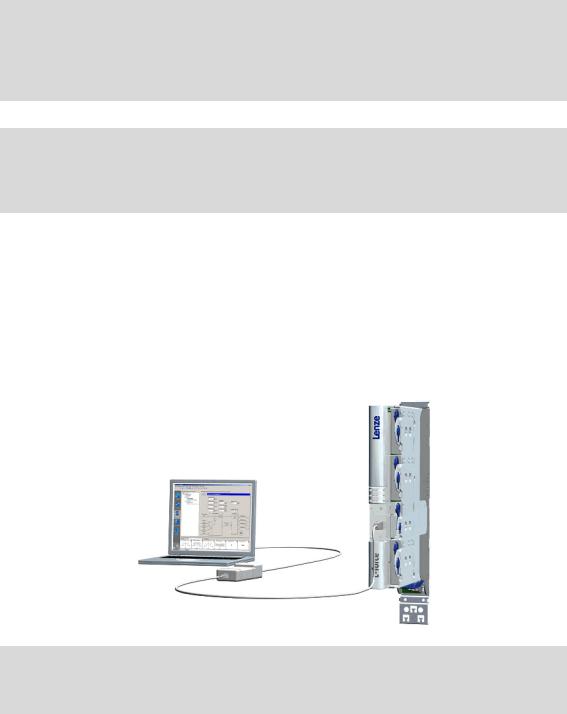
2.2.1Going online via diagnostic adapter
For initial commissioning of the controller you can for instance use the diagnostic adapter offered by Lenze:
Note!
Please observe the documentation for the diagnostic adapter!
Lenze · Servo-Inverter 9400 HighLine · Reference manual · DMS 10.0 EN · 11/2013 · TD05/06 |
17 |
2 Introduction
2.2Communicating with the controller
_ _ _ _ _ _ _ _ _ _ _ _ _ _ _ _ _ _ _ _ _ _ _ _ _ _ _ _ _ _ _ _ _ _ _ _ _ _ _ _ _ _ _ _ _ _ _ _ _ _ _ _ _ _ _ _ _ _ _ _ _ _ _ _
Preconditions:
•The diagnostic adapter is connected to the controller at the diagnostic interface X6 and to the PC at a free USB port.
•The driver required for the diagnostic adapter is installed.
•The control electronics of the controller is supplied with 24 V low voltage via plug X2.
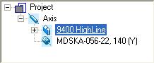
How to build up an online connection via the diagnostic adapter:
1.Select the 9400 HighLine controller to which you want to build up an online connection in the Project view of the »Engineer«:
2.Click the  icon.
icon.
If the changes you have made on the project have not been accepted yet, first a query on whether an update is to be carried out is effected.
If an update is to be carried out:
•Click on Yes to open the Update project dialog box.
•Press the Create button in the Update project dialog box to update the changed project elements.
•After the update a note is shown, saying whether the update was carried out successfully.
18 |
Lenze · Servo-Inverter 9400 HighLine · Reference manual · DMS 10.0 EN · 11/2013 · TD05/06 |
2 Introduction
2.2Communicating with the controller
_ _ _ _ _ _ _ _ _ _ _ _ _ _ _ _ _ _ _ _ _ _ _ _ _ _ _ _ _ _ _ _ _ _ _ _ _ _ _ _ _ _ _ _ _ _ _ _ _ _ _ _ _ _ _ _ _ _ _ _ _ _ _ _
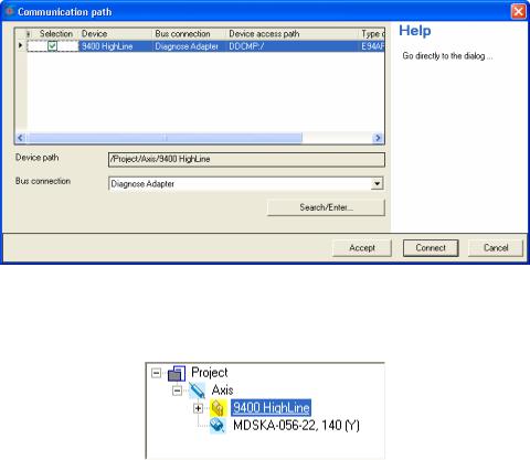
If no communication path was configured yet for the controller selected, the
Communication path dialog box is shown after the update has been carried out:
•The "Diagnostic adapter" bus connection is already preset.
3.Click on Connect.
•The dialog box is closed and the online connection with the controller is built up.
•In the Project view a yellow icon indicates the online connection with the controller:
Now you can use the icons  and
and  to easily build up and end a connection with the controller. The communication settings are only required when communication with a controller is built up for the first time.
•If you want to change the configured communication path, select the command Online Set communication path and go online to open the Communication path dialog box and change the settings.
•When an online connection has been established, the »Engineer« displays the current parameter settings of the controller with a yellow background colour.
Lenze · Servo-Inverter 9400 HighLine · Reference manual · DMS 10.0 EN · 11/2013 · TD05/06 |
19 |

2 Introduction
2.2Communicating with the controller
_ _ _ _ _ _ _ _ _ _ _ _ _ _ _ _ _ _ _ _ _ _ _ _ _ _ _ _ _ _ _ _ _ _ _ _ _ _ _ _ _ _ _ _ _ _ _ _ _ _ _ _ _ _ _ _ _ _ _ _ _ _ _ _
2.2.2Going online via system bus (CAN on board)
As an alternative to the diagnostic adapter, you can use the integrated system bus interface (CAN on board, terminal X1) of the controller for communication.
• Lenze offers the following communication accessories for connection to the PC:
Communication accessories |
PC interface |
PC system bus adapter 2173 |
Parallel interface |
incl. connection cable and voltage supply adapter |
(LPT port) |
•for DIN keyboard connection (EMF2173IB)
•for PS/2 keyboard connection (EMF2173IBV002)
•for PS/2 keyboard connection with electrical isolation (EMF2173IBV003)
PC system bus adapter 2177 |
USB |
incl. connection cable (EMF2177IB) |
(Universal Serial Bus) |
Note!
•For detailed information about the PC system bus adapter, please see the "CAN Communication Manual".
•Please observe the documentation for the PC system bus adapter!
•The online connection is established as described in the previous chapter "Going online via diagnostic adapter", only that this time the entry "CAN system bus" is to be selected in the Bus connection list field of the Communication path dialog box. ( 18)
2.2.3Use of other communication interfaces
The controller can be extended by further communication interfaces, if required, e.g. Ethernet, ETHERNET Powerlink, or PROFIBUS.
•For this the controller is provided with the module slots MXI1 and MXI2 for accepting communication modules.
•Detailed information on this subject can be found in the Hardware Manual and Communication Manual for the corresponding communication system.
20 |
Lenze · Servo-Inverter 9400 HighLine · Reference manual · DMS 10.0 EN · 11/2013 · TD05/06 |
2 Introduction
2.3Signal types & scaling
_ _ _ _ _ _ _ _ _ _ _ _ _ _ _ _ _ _ _ _ _ _ _ _ _ _ _ _ _ _ _ _ _ _ _ _ _ _ _ _ _ _ _ _ _ _ _ _ _ _ _ _ _ _ _ _ _ _ _ _ _ _ _ _
2.3Signal types & scaling
It is very helpful for the parameterisation & configuration of the controller to know the signal types and their scaling listed below, which serve to process physical quantities (e.g. a speed or position) within the function block interconnection.
Note!
From software version V3.0 the resolution of an encoder revolution can be parameterised in C00100 (Lenze setting: 16 bits/encoder revolution).
Resolution of an encoder revolution ( 37)
Signal type (data type) |
Connection |
Resolution |
Value range (external) |
|
|
Decimal positions/ |
|
|
|
symbol in |
|
|
|
|
signal type suffix |
||
|
the FB editor |
|
|
|
|
in the identifier |
||
Scaled (INT) |
|
16 bits |
± 199.99 % |
|
|
2 |
|
_a |
Scaled (DINT) |
|
32 bits |
± 200.00 % |
|
|
2 |
|
_n |
Speed (INT) |
/ |
16 bits |
± 30000.0 rpm |
|
|
1 |
|
_v |
Speed (DINT) |
|
32 bits |
± 480000.0 rpm |
|
|
1 |
|
_s |
Position/angle (DINT) |
/ |
32 bits |
-231 ... 231-1 increments |
|
|
3 |
|
_p |
Digital (BOOL) |
|
Bit 1 |
0 ≡ FALSE; 1 ≡ TRUE |
|
|
0 |
|
|
Acceleration (DINT) |
|
32 bits |
± 7.69 * 109 rpm/s |
|
|
3 |
|
_x |
Time |
|
28 bits |
0 ... 268435.456 s |
|
|
3 |
|
|
Other (BYTE) |
|
8 bits |
0 ... 255 |
|
|
0 |
|
|
Other (WORD) |
|
16 bits |
0 ... 65535 |
|
|
0 |
|
|
Other (DWORD) |
|
32 bits |
0 ... 4294967295 |
|
|
0 |
|
|
Other (INT) |
|
16 bits |
-32768 ... 32767 |
|
|
0 |
|
|
Other (DINT) |
|
32 bits |
-2147483648 ... 2147483647 |
|
|
0 |
|
|
Scaling of physical units |
|
|
|
|
|
|
|
|
|
|
|
|
|
|
|
|
|
Signal type |
Connection |
Resolution |
Scaling |
|
|
|
|
|
|
symbol in |
|
External value |
|
≡ internal value |
|
||
|
|
|
|
|||||
|
the FB editor |
|
|
|
||||
Scaled (INT) |
|
16 bits |
100 % |
|
≡ 214 ≡ 16384 |
|
||
Scaled (DINT) |
|
32 bits |
100 % |
|
≡ 230 ≡ 1073741824 |
|
||
Speed (INT) |
/ |
16 bits |
15000 rpm |
|
≡ 214 ≡ 16384 |
|
||
Speed (DINT) |
|
32 bits |
15000 rpm |
|
≡ 226 ≡ 67108864 |
|
||
Position/angle (DINT) |
/ |
32 bits |
1 encoder revolution |
|
≡ 216 increments |
|
||
Acceleration (DINT) |
|
32 bits |
15000000 rpm/s |
|
≡ 222 ≡ 4194304 |
|
||
Lenze · Servo-Inverter 9400 HighLine · Reference manual · DMS 10.0 EN · 11/2013 · TD05/06 |
21 |
3 Commissioning
_ _ _ _ _ _ _ _ _ _ _ _ _ _ _ _ _ _ _ _ _ _ _ _ _ _ _ _ _ _ _ _ _ _ _ _ _ _ _ _ _ _ _ _ _ _ _ _ _ _ _ _ _ _ _ _ _ _ _ _ _ _ _ _
3 Commissioning
This documentation contains detailed information on parameter setting and configuration of the controller. Sequential reading is not required.
In order to obtain the information relevant for initial commissioning, this chapter describes different commissioning scenarios which can also be used as a guide through this manual:
A.Initial commissioning ( 25)
•Target: Adapting the controller to the electromechanics and the control system.
B.Standard set-up ( 26)
•Target: Taking over the application and parameter set of an already preconfigured "Engineer" project into several controllers.
C.Controller replacement ( 27)
•Target: Replacing a controller which has failed in a running system by a replacement device using the "old" memory module.
D.Motor replacement ( 27)
•Target: Replacing a motor which has failed in a running system.
22 |
Lenze · Servo-Inverter 9400 HighLine · Reference manual · DMS 10.0 EN · 11/2013 · TD05/06 |

3 Commissioning
3.1General information
_ _ _ _ _ _ _ _ _ _ _ _ _ _ _ _ _ _ _ _ _ _ _ _ _ _ _ _ _ _ _ _ _ _ _ _ _ _ _ _ _ _ _ _ _ _ _ _ _ _ _ _ _ _ _ _ _ _ _ _ _ _ _ _
3.1General information
Note!
Some parameters of the controller have a setting range depending on the device type.
If parameterisation is carried out offline or if the memory module is exchanged between different 9400 HighLine device types, always check the settings of the parameters listed in the following table and adapt them, if required, to prevent a parameter error after the parameter set download or module change!
Parameter |
Info |
Lenze setting |
|
C00018 |
Switching frequency |
8 kHz variable |
|
C00022 |
Maximum current |
0.00 A |
|
|
Accepting/adapting plant parameters ( 124) |
|
|
C00173 |
Mains voltage and undervoltage threshold (LU) |
400/415 V, LU = 285 V |
|
C00174 |
Machine parameters ( 29) |
|
|
Tip!
The rated data of the different device types can be found in the Hardware Manual in the "Rated data" chapter.
Term definition of "Plant parameters"
The term "plant parameters" which is frequently used in the following chapters summarises all parameters which result from the combination of motor and load. They characterise the transfer behaviour of the entire controlled system including the desired monitoring functions. The plant parameters depend on the application in which the controller and motor are used.
Lenze · Servo-Inverter 9400 HighLine · Reference manual · DMS 10.0 EN · 11/2013 · TD05/06 |
23 |
3 Commissioning
3.2Notes on commissioning using the keypad
_ _ _ _ _ _ _ _ _ _ _ _ _ _ _ _ _ _ _ _ _ _ _ _ _ _ _ _ _ _ _ _ _ _ _ _ _ _ _ _ _ _ _ _ _ _ _ _ _ _ _ _ _ _ _ _ _ _ _ _ _ _ _ _
3.2Notes on commissioning using the keypad
For a motor with an electronic nameplate (ENP)
•A display of the plant parameters offered by ENP via keypad is not provided. The plant parameters must be edited and optimised individually.
•To avoid that the motor starts unintentionally without adjusting the plant parameters, the maximum current in the Lenze setting is set to "0 A" in C00022.
•After setting the plant parameters, they have to be saved on the memory module of the controller with mains failure protection, just as the motor data that have been read out from the ENP (C00002 = "11: Save start parameters").
For a motor without an electronic nameplate (ENP)
•The motor data and plant parameters must be edited and set individually.
•To avoid that the motor starts unintentionally without adjusting the plant parameters, the maximum current is set to "0 A" in C00022 by the factory.
•After setting the motor data and plant parameters, they have to be saved on the memory module of the controller with mains failure protection (C00002 = "11: Save start parameters").
Commissioning of the application
•The application must already be stored on the memory module of the controller. Otherwise commissioning by only using the keypad is not possible.
•All application parameters which deviate from the factory adjustment have to be edited individually. For this the project planner has to provide a corresponding list to the commissioner (including the motor and plant data).
•In the case of a standard set-up, a pole position identification may have to be carried out for synchronous motors of a third party manufacturer or Lenze synchronous motors with a Stegmann absolute value encoder.
•After setting the parameters, they have to be saved on the memory module of the controller with mains failure protection (C00002 = "11: Save start parameters").
Tip!
Detailed information on the individual technology applications can be found in the corresponding Software Manual for the technology application and the »Engineer« online help in the chapter "L-force Servo Drives 9400 Technology applications".
24 |
Lenze · Servo-Inverter 9400 HighLine · Reference manual · DMS 10.0 EN · 11/2013 · TD05/06 |

3 Commissioning
3.3Initial commissioning
_ _ _ _ _ _ _ _ _ _ _ _ _ _ _ _ _ _ _ _ _ _ _ _ _ _ _ _ _ _ _ _ _ _ _ _ _ _ _ _ _ _ _ _ _ _ _ _ _ _ _ _ _ _ _ _ _ _ _ _ _ _ _ _
3.3Initial commissioning
Worksteps
Parameterising motor control:
1.Read out the motor data of the controller or select them via the »Engineer« motor catalogue.
•If the motor connected to the controller is provided with an electronic nameplate (ENP), all motor data are automatically read out from the ENP and a selection in the motor catalogue is not required.Reading out motor data from the controller ( 117)
•If a motor without ENP or a motor by a third-party manufacturer is used, the selection is carried out via the »Engineer« motor catalogue. Selecting a motor from the motor catalogue in the »Engineer« ( 118)
2.Select motor control. ( 121)
•Servo control is preset for the synchronous motor.
3.Adjusting motor and controller to each other ( 123)
4.Carry out settings for selected motor control.
•For this see description for the corresponding motor control:
•Servo control (SC)
•Sensorless vector control (SLVC) (from software version V3.0)
•V/f control (VFCplus) (from software version V3.0)
•V/f control (VFCplus) (from software version V3.0)
Parameterise/configure application:
5. Load & parameterise technology application.
Detailed information on the individual technology applications can be found in the corresponding Software Manual for the technology application and the »Engineer« online help in the chapter "L-force Servo Drives 9400 Technology applications".
6.If required, reconfigure the interconnection of the technology application with the function block editor.
Optimise control mode:
7.Optimise control mode of the selected motor control.
•By means of traversing profile from the application and oscilloscope.
•For this see description for the corresponding motor control:
•Servo control (SC)
•Sensorless vector control (SLVC) (from software version V3.0)
•V/f control (VFCplus) (from software version V3.0)
•V/f control (VFCplus) (from software version V3.0)
Save project and parameter set:
8.Execute device command C00002 = "11: Save start parameters".
9.Save »Engineer« project.
More (optional) worksteps
Worksteps
Establish network:
1.Insert network and machine application into the »Engineer« project.
2.Interconnect port blocks reasonably to each other within the machine application.
3.Configure network (set addresses, baud rate, and process data channels in a reasonable manner).
4.Establish communication with the control system.
5.Establish communication with other drive components (e.g. HMIs, I/O extensions and other controllers).
Lenze · Servo-Inverter 9400 HighLine · Reference manual · DMS 10.0 EN · 11/2013 · TD05/06 |
25 |

3 Commissioning
3.4Standard set-up
_ _ _ _ _ _ _ _ _ _ _ _ _ _ _ _ _ _ _ _ _ _ _ _ _ _ _ _ _ _ _ _ _ _ _ _ _ _ _ _ _ _ _ _ _ _ _ _ _ _ _ _ _ _ _ _ _ _ _ _ _ _ _ _
Worksteps
Check & optimise application/DC-bus operation:
1.Traverse axis in manual operation.
•See chap. Basic drive functions Manual jog ( 395)
2.Check area boundaries (path, speed, torque).
3.Traverse axis in automatic operation with set-up speed, possibly together with coupled axes.
4.Check coupling with other movements (master/slave axes, tools, …).
5.Optimisation of the process at higher speeds.
6.Recording of typical signal characteristics using the oscilloscope function for the documentation.
•See chapter Oscilloscope ( 579)
Save & archive project and parameter set:
1.Execute device command C00002 = "11: Save start parameters".
2.Save »Engineer« project.
3.Deposit a backup copy of the »Engineer« project, e.g. on CD ROM, in the control cabinet.
3.4Standard set-up
Worksteps
Transfer application and parameter set to the controller:
1.Transfer the application preconfigured in »Engineer« and the corresponding parameter set to the memory module of the controller.
2.Execute device command C00002 = "11: Save start parameters".
For a motor with an electronic nameplate (ENP):
3.Restart controller with connected motor to read out the motor data from the electronic nameplate (ENP).
•Either by switching off/switching on again the voltage supply or by means of device command C00002 = "11000: Restart controller".
•See chap. Motor interface Reading out motor data from the controller ( 117)
4.Execute device command C00002 = "11: Save start parameters".
For a motor without an electronic nameplate (ENP):
Note:The motor is operated with the motor data and plant parameters identified during initial commissioning. Adjusting motor and controller to each other ( 123)
26 |
Lenze · Servo-Inverter 9400 HighLine · Reference manual · DMS 10.0 EN · 11/2013 · TD05/06 |

3 Commissioning
3.5Controller replacement
_ _ _ _ _ _ _ _ _ _ _ _ _ _ _ _ _ _ _ _ _ _ _ _ _ _ _ _ _ _ _ _ _ _ _ _ _ _ _ _ _ _ _ _ _ _ _ _ _ _ _ _ _ _ _ _ _ _ _ _ _ _ _ _
3.5Controller replacement
Scenario: The controller has failed in a running system.
Note!
For the procedure described in the following it is assumed that the memory module and possibly available extension modules in the controller, as well as the motor are not affected by the failure and that all parameters have been saved with mains failure protection.
Worksteps
Replacement of the controller:
1.Replace controller.
See Mounting Instructions for the controller!
2.Insert the memory module of the failed controller into the replacement device.
3.If further extension modules are plugged into the failed controller, they must be inserted into the replacement device as well.
Further steps are not required since all data required are on the memory module.
3.6Motor replacement
Scenario: The motor has failed in a running system.
Note!
For the procedure described in the following it is assumed that the controller is not affected by the failure.
Worksteps
Replacement of the motor:
1.Replace the motor.
See Mounting Instructions for the controller!
The motor connection on the controller is accessible without having to remove the standard device from the installation backplane.Note:
For a motor with an electronic nameplate (ENP):
2.Restart controller with connected motor to read out the motor data from the electronic nameplate.
•Either by switching off/switching on again the voltage supply or by means of device command C00002 = "11000: Restart controller".
•See chap. Motor interface Reading out motor data from the controller ( 117)
3.Execute device command C00002 = "11: Save start parameters".
For a motor without an electronic nameplate (ENP):
Note:The motor is operated with the motor data and plant data from the memory module.
Lenze · Servo-Inverter 9400 HighLine · Reference manual · DMS 10.0 EN · 11/2013 · TD05/06 |
27 |
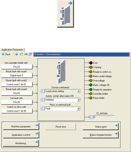
4 Drive interface
_ _ _ _ _ _ _ _ _ _ _ _ _ _ _ _ _ _ _ _ _ _ _ _ _ _ _ _ _ _ _ _ _ _ _ _ _ _ _ _ _ _ _ _ _ _ _ _ _ _ _ _ _ _ _ _ _ _ _ _ _ _ _ _
4 |
Drive interface |
This chapter provides you with information on the drive interface via which you can control the drive controller into specific states and call different pieces of status information of the controller. Furthermore the machine constants for the motor end are entered via the drive interface.
How to get to the dialog for setting the drive interface parameters:
1.Go to the Project view of the »Engineer« and select the 9400 HighLine controller.
2.Select the Application parameters tab from the Workspace.
3.Click the following button of the Overview dialog level:
Parameterisation dialog in the »Engineer«
•The white buttons indicate the configuration of the drive interface inputs. Internal interfaces | "LS_DriveInterface" system block ( 110)
•The assignment is predefined by the technology application selected (in the example "Actuating drive – speed"). If required, this assignment configuration can be changed by clicking the corresponding buttons.
•If you click a button marked with the  symbol, you go one level deeper in the corresponding parameterisation dialog.
28 |
Lenze · Servo-Inverter 9400 HighLine · Reference manual · DMS 10.0 EN · 11/2013 · TD05/06 |

4 Drive interface
4.1Machine parameters
_ _ _ _ _ _ _ _ _ _ _ _ _ _ _ _ _ _ _ _ _ _ _ _ _ _ _ _ _ _ _ _ _ _ _ _ _ _ _ _ _ _ _ _ _ _ _ _ _ _ _ _ _ _ _ _ _ _ _ _ _ _ _ _
4.1Machine parameters
The global machine constants ("machine parameters") are set in the »Engineer» on the Application parameters tab in the dialog level Overview Drive interface Machine parameters:
Tip!
Detailed information on the different machine parameters can be obtained from the following subchapters.
Lenze · Servo-Inverter 9400 HighLine · Reference manual · DMS 10.0 EN · 11/2013 · TD05/06 |
29 |

4 Drive interface
4.1Machine parameters
_ _ _ _ _ _ _ _ _ _ _ _ _ _ _ _ _ _ _ _ _ _ _ _ _ _ _ _ _ _ _ _ _ _ _ _ _ _ _ _ _ _ _ _ _ _ _ _ _ _ _ _ _ _ _ _ _ _ _ _ _ _ _ _
4.1.1Mains voltage
Via the Mains voltage list field (C00173) the mains voltage for the controller is set.
•If you set a mains voltage with an adjustable threshold for undervoltage ("LU adjustable"), this undervoltage threshold can be set in the Undervoltage threshold (LU) input field (C00174).
•In the Resp. to DC-bus overvoltage list field (C00600) you can select the response that is to be effected when a DC-bus overvoltage occurs.
Note!
Changing the setting in C00173 also affects the permissible device utilisation!
Tip!
In the chapter "Rated data" of the hardware manual the device types and their permissible device utilisation at a certain mains voltage and switching frequency are specified.
See also: Monitoring of the device utilisation ( 108)
30 |
Lenze · Servo-Inverter 9400 HighLine · Reference manual · DMS 10.0 EN · 11/2013 · TD05/06 |
Loading...