


E84AYCER
Table of contents
 Loading...
EDS84AYCER
13358692
Ä.Dw}ä
L-force Communication
Communication Manual
8400
E84AYCER
PROFINET communication module
L

2 L EDS84AYCER EN 2.0 - 11/2010

E84AYCER communication manual (PROFINET)
Contents
Contents
1 About this documentation . . . . . . . . . . . . . . . . . . . . . . . . . . . . . . . . . . . . . . . . . . . . . . . . . . . . . . . . . 6
1.1 Document history
1.2 Conventions used
1.3 Terminology used
1.4 Notes used
2 Safety instructions
2.1 General safety instructions and application notes
2.2 Device- and application-specific safety instructions
2.3 Residual hazards
3 Product description
3.1 Application as directed
3.2 Identification
3.3 Properties
3.4 Terminals and interfaces
4 Technical data
4.1 General data and operating conditions
. . . . . . . . . . . . . . . . . . . . . . . . . . . . . . . . . . . . . . . . . . . . . . . . . . . . . . . . . . . . . . . . . . . . . . 11
. . . . . . . . . . . . . . . . . . . . . . . . . . . . . . . . . . . . . . . . . . . . . . . . . . . . . . . . . . . . . . . . . . . . . . 15
. . . . . . . . . . . . . . . . . . . . . . . . . . . . . . . . . . . . . . . . . . . . . . . . . . . . . . . . . . . . . . . . . . . . 16
. . . . . . . . . . . . . . . . . . . . . . . . . . . . . . . . . . . . . . . . . . . . . . . . . . . . . . . . . . . . . . . 8
. . . . . . . . . . . . . . . . . . . . . . . . . . . . . . . . . . . . . . . . . . . . . . . . . . . . . . . . . . . . . . . 9
. . . . . . . . . . . . . . . . . . . . . . . . . . . . . . . . . . . . . . . . . . . . . . . . . . . . . . . . . . . . . . . 10
. . . . . . . . . . . . . . . . . . . . . . . . . . . . . . . . . . . . . . . . . . . . . . . . . . . . . . . . . . . . . . . .12
. . . . . . . . . . . . . . . . . . . . . . . . . . . . . . . . . . . . . . . . . . . . . . . . . . . . . . . . . . . . . . . . 13
. . . . . . . . . . . . . . . . . . . . . . . . . . . . . . . . . . . . . . . . . . . . . . . . . . . . . . . . . . . . . . . 14
. . . . . . . . . . . . . . . . . . . . . . . . . . . . . . . . . . . . . . . . . . . . . . . . . . . . . . . . . . 14
. . . . . . . . . . . . . . . . . . . . . . . . . . . . . . . . . . . . . . . . . . . . . . . . . . . . . . . . . . . . . . . . . . . 14
. . . . . . . . . . . . . . . . . . . . . . . . . . . . . . . . . . . . . . . . . . . . . . . . . . . . . . . . 15
. . . . . . . . . . . . . . . . . . . . . . . . . . . . . . . . . 12
. . . . . . . . . . . . . . . . . . . . . . . . . . . . . . . 13
. . . . . . . . . . . . . . . . . . . . . . . . . . . . . . . . . . . . . . . . . . . 16
4.2 Protective insulation
4.3 Protocol data
4.4 Communication time
4.5 Internal switch latency
4.6 Dimensions
5 Installation
5.1 Mechanical installation
5.2 Electrical installation
. . . . . . . . . . . . . . . . . . . . . . . . . . . . . . . . . . . . . . . . . . . . . . . . . . . . . . . . . . . . . . . . . . . . . . . 22
5.1.1 Mounting for standard devices 0.25 kW and 0.37 kW
5.1.2 Mounting for standard devices from 0.55 kW
5.1.3 Replacing the communication module
5.2.1 EMC-compliant wiring
5.2.2 Network topology
5.2.3 PROFINET connection
5.2.4 Specification of the Ethernet cable
5.2.5 External voltage supply
. . . . . . . . . . . . . . . . . . . . . . . . . . . . . . . . . . . . . . . . . . . . . . . . . . . . . . . . . . . . 17
. . . . . . . . . . . . . . . . . . . . . . . . . . . . . . . . . . . . . . . . . . . . . . . . . . . . . . . . . . . . . . . . . . . 19
. . . . . . . . . . . . . . . . . . . . . . . . . . . . . . . . . . . . . . . . . . . . . . . . . . . . . . . . . . . . 19
. . . . . . . . . . . . . . . . . . . . . . . . . . . . . . . . . . . . . . . . . . . . . . . . . . . . . . . . . . 20
. . . . . . . . . . . . . . . . . . . . . . . . . . . . . . . . . . . . . . . . . . . . . . . . . . . . . . . . . . . . . . . . . . . . . 21
. . . . . . . . . . . . . . . . . . . . . . . . . . . . . . . . . . . . . . . . . . . . . . . . . . . . . . . . . . 23
. . . . . . . . . . . . . . . . . . . . . . 23
. . . . . . . . . . . . . . . . . . . . . . . . . . . . . 24
. . . . . . . . . . . . . . . . . . . . . . . . . . . . . . . . . . . . 25
. . . . . . . . . . . . . . . . . . . . . . . . . . . . . . . . . . . . . . . . . . . . . . . . . . . . . . . . . . . . 26
. . . . . . . . . . . . . . . . . . . . . . . . . . . . . . . . . . . . . . . . . . . . . . . . . . . 26
. . . . . . . . . . . . . . . . . . . . . . . . . . . . . . . . . . . . . . . . . . . . . . . . . . . . . . . 26
. . . . . . . . . . . . . . . . . . . . . . . . . . . . . . . . . . . . . . . . . . . . . . . . . . . . 28
. . . . . . . . . . . . . . . . . . . . . . . . . . . . . . . . . . . . . . . . 30
. . . . . . . . . . . . . . . . . . . . . . . . . . . . . . . . . . . . . . . . . . . . . . . . . . 32
EDS84AYCER EN 2.0 - 11/2010 L 3

E84AYCER communication manual (PROFINET)
Contents
6 Commissioning . . . . . . . . . . . . . . . . . . . . . . . . . . . . . . . . . . . . . . . . . . . . . . . . . . . . . . . . . . . . . . . . . . . 34
6.1 Before initial switch-on
6.2 Configuring the PROFINET IO controller
6.3 Setting the station name
6.4 Setting the IP configuration
6.5 Initial switch-on
7 Data transfer
8 Process data transfer
8.1 Accessing process data / PDO mapping
8.2 Preconfigured port interconnection of the process data objects (PDO)
8.3 Configuring the port interconnection of the process data objects (PDO) freely
9 Parameter data transfer
9.1 The acyclic channel (PROFIdrive profile)
9.1.1 Connection establishment of an IO controller to an IO device
9.1.2 Acyclic data transmission process
9.1.3 Structure of the PROFINET data telegram
9.2 Reading parameters from the controller
9.2.1 Response after a correct read request
9.2.2 Response after a read error
9.2.3 Telegram example: Read request
. . . . . . . . . . . . . . . . . . . . . . . . . . . . . . . . . . . . . . . . . . . . . . . . . . . . . . . . . . . . . . . . . . . . . 41
. . . . . . . . . . . . . . . . . . . . . . . . . . . . . . . . . . . . . . . . . . . . . . . . . . . . . . . . . . 34
. . . . . . . . . . . . . . . . . . . . . . . . . . . . . . . . . . . . . . . . . . 35
. . . . . . . . . . . . . . . . . . . . . . . . . . . . . . . . . . . . . . . . . . . . . . . . . . . . . . . . 36
. . . . . . . . . . . . . . . . . . . . . . . . . . . . . . . . . . . . . . . . . . . . . . . . . . . . . . 38
. . . . . . . . . . . . . . . . . . . . . . . . . . . . . . . . . . . . . . . . . . . . . . . . . . . . . . . . . . . . . . . . . 40
. . . . . . . . . . . . . . . . . . . . . . . . . . . . . . . . . . . . . . . . . . . . . . . . . . . . . . . . . . . . . . 42
. . . . . . . . . . . . . . . . . . . . . . . . . . . . . . . . . . . . . . . . . . . 42
. . . . . . . . . . . . . . 43
. . . . . . 44
. . . . . . . . . . . . . . . . . . . . . . . . . . . . . . . . . . . . . . . . . . . . . . . . . . . . . . . . . . . 48
. . . . . . . . . . . . . . . . . . . . . . . . . . . . . . . . . . . . . . . . . . . 48
. . . . . . . . . . . . . . 48
. . . . . . . . . . . . . . . . . . . . . . . . . . . . . . . . . . . . . . . . . 49
. . . . . . . . . . . . . . . . . . . . . . . . . . . . . . . . . 50
. . . . . . . . . . . . . . . . . . . . . . . . . . . . . . . . . . . . . . . . . . 51
. . . . . . . . . . . . . . . . . . . . . . . . . . . . . . . . . . . . . 52
. . . . . . . . . . . . . . . . . . . . . . . . . . . . . . . . . . . . . . . . . . . . . . . 53
. . . . . . . . . . . . . . . . . . . . . . . . . . . . . . . . . . . . . . . . . 54
9.3 Writing parameters to the controller
9.3.1 Response after a correct write request
9.3.2 Response after a write error
9.3.3 Telegram example: Write request
9.4 Error information (error)
9.5 Consistent parameter data
10 Monitoring
11 Diagnostics
11.1 LED status displays
11.2 Diagnostics with the »Engineer«
11.3 Diagnostic data
. . . . . . . . . . . . . . . . . . . . . . . . . . . . . . . . . . . . . . . . . . . . . . . . . . . . . . . . . . . . . . . . . . . . . . . 65
. . . . . . . . . . . . . . . . . . . . . . . . . . . . . . . . . . . . . . . . . . . . . . . . . . . . . . . . . . . . . . . . . . . . . . . 66
. . . . . . . . . . . . . . . . . . . . . . . . . . . . . . . . . . . . . . . . . . . . . . . . . . . . . . . . . . . . . . 66
11.1.1 Module status displays
11.1.2 Fieldbus status displays
11.1.3 Status displays at X256 and X257
. . . . . . . . . . . . . . . . . . . . . . . . . . . . . . . . . . . . . . . . . . . . . . . . . . . . . . . . . . . . . . . . . 71
. . . . . . . . . . . . . . . . . . . . . . . . . . . . . . . . . . . . . . . . . . . . . 56
. . . . . . . . . . . . . . . . . . . . . . . . . . . . . . . . . . . . 58
. . . . . . . . . . . . . . . . . . . . . . . . . . . . . . . . . . . . . . . . . . . . . . 58
. . . . . . . . . . . . . . . . . . . . . . . . . . . . . . . . . . . . . . . . 60
. . . . . . . . . . . . . . . . . . . . . . . . . . . . . . . . . . . . . . . . . . . . . . . . . . . . . . . . . 62
. . . . . . . . . . . . . . . . . . . . . . . . . . . . . . . . . . . . . . . . . . . . . . . . . . . . . . 64
. . . . . . . . . . . . . . . . . . . . . . . . . . . . . . . . . . . . . . . . . . . . . . . . . . . 67
. . . . . . . . . . . . . . . . . . . . . . . . . . . . . . . . . . . . . . . . . . . . . . . . . . 68
. . . . . . . . . . . . . . . . . . . . . . . . . . . . . . . . . . . . . . . . . 69
. . . . . . . . . . . . . . . . . . . . . . . . . . . . . . . . . . . . . . . . . . . . . . . . . 70
4 L EDS84AYCER EN 2.0 - 11/2010

E84AYCER communication manual (PROFINET)
Contents
12 Error messages . . . . . . . . . . . . . . . . . . . . . . . . . . . . . . . . . . . . . . . . . . . . . . . . . . . . . . . . . . . . . . . . . . . 73
12.1 Short overview (A-Z) of the PROFINET error messages
12.2 Possible causes and remedies
13 Parameter reference
13.1 Parameters of the communication module
13.2 Table of attributes
14 Index
. . . . . . . . . . . . . . . . . . . . . . . . . . . . . . . . . . . . . . . . . . . . . . . . . . . . . . . . . . . . . . . . . . . . . . . . . . . . 91
. . . . . . . . . . . . . . . . . . . . . . . . . . . . . . . . . . . . . . . . . . . . . . . . . . . . . . . . . . . . . . . 78
. . . . . . . . . . . . . . . . . . . . . . . . . . . . . . . . . . . . . . . . . . . . . . . . . . . . . . . . . . . . . . 89
. . . . . . . . . . . . . . . . . . . . . . . . . . . . . . . . . . . . . . . . . . . . . . . . . . . . 74
. . . . . . . . . . . . . . . . . . . . . . . . . . . . . 73
. . . . . . . . . . . . . . . . . . . . . . . . . . . . . . . . . . . . . . . 78
EDS84AYCER EN 2.0 - 11/2010 L 5

E84AYCER communication manual (PROFINET)
About this documentation
1 About this documentation
Contents
The descriptions in this documentation only refer to the E84AYCER communication
module (PROFINET).
Note!
This documentation supplements the mounting instructions supplied with the
communication module and the "Inverter Drives 8400" hardware manual.
The features and functions of the communication module are described in detail.
Examples illustrate typical applications.
This documentation also contains...
Safety instructions that must be observed
Key technical data relating to the communication module
Information about the versions of the Lenze standard devices to be used
Notes on troubleshooting and fault elimination
The theoretical concepts are only explained to the level of detail required to understand
the function of the communication module.
Depending on the software version of the controller and the version of the »Engineer«
software installed, the screenshots in this documentation may deviate from the
»Engineer« representation.
This documentation does not describe any software provided by other manufacturers. No
liability can be accepted for corresponding data provided in this documentation. For
information on how to use the software, please refer to the host system (master)
documents.
All brand names mentioned in this documentation are trademarks of their respective
owners.
Tip!
Detailed information on PROFINET is provided on the homepage of the PROFIBUS
user organisation which also develops PROFINET communication technology:
www.profibus.com
6 L EDS84AYCER EN 2.0 - 11/2010

E84AYCER communication manual (PROFINET)
About this documentation
Target group
This documentation addresses to persons who configure, install, commission, and
maintain the networking and remote maintenance of a machine.
Tip!
Documentation and software updates of Lenze products can be found on the
Internet in the "Services & Downloads" area at:
www.Lenze.com
Validity information
The information in this documentation is valid for the following devices:
Extension module Type designation From hardware
PROFINET communication module E84AYCER VA 02.00
version
From software
version
EDS84AYCER EN 2.0 - 11/2010 L 7

E84AYCER communication manual (PROFINET)
About this documentation
Document history
1.1 Document history
Material number Version Description
13313969 1.0 04/2010 TD17 First edition
13358692 2.0 11/2010 TD17 • General revision
• Update for SW version 02.00
Your opinion is important to us!
These instructions were created to the best of our knowledge and belief to give you the
best possible support for handling our product.
Perhaps we have not succeeded in achieving this objective in every respect. If you notice
this, please send your suggestions and points of criticism in a short e-mail to:
feedback-docu@Lenze.de
Thank you very much for your support.
Your Lenze documentation team
8 L EDS84AYCER EN 2.0 - 11/2010

1.2 Conventions used
This documentation uses the following conventions to distinguish between different types
of information:
Type of information Identification Examples/notes
Spelling of numbers
Decimal Standard spelling Example: 1234
Hexadecimal 0x[0 ... 9, A ... F] Example: 0x60F4
Binary
• Nibble
Decimal separator Point The decimal point is always used.
Text
Program name » « PC software
Control element Bold The OK button... / The Copy command... / The
Hyperlink Underlined
Symbols
Page reference ( 9) Optically highlighted reference to another page. In
Step-by-step instructions
E84AYCER communication manual (PROFINET)
About this documentation
Conventions used
In inverted commas
Point
Example: ’100’
Example: ’0110.0100’
For example: 1234.56
Example: Lenze »Engineer«
Properties tab... / The Name input field...
Optically highlighted reference to another topic. In
this documentation it is activated via mouse-click.
this documentation it is activated via mouse-click.
Step-by-step instructions are indicated by a
pictograph.
EDS84AYCER EN 2.0 - 11/2010 L 9

E84AYCER communication manual (PROFINET)
About this documentation
Terminology used
1.3 Terminology used
Term Meaning
Controller Lenze frequency inverter of the "Inverter Drives 8400" product series which the
Standard device
»Engineer« Lenze software which supports you throughout the whole machine life cycle -
Code "Container" for one or several parameters used to parameterise or monitor the
Subcode If a code contains several parameters they are stored in so-called "subcodes".
HW Hardware
SW Software
I/O controller PROFINET master
I/O device PROFINET slave
IO supervisor Engineering and diagnostics tools
communication module can be used with.
Application as directed
from planning to maintenance.
device.
This manual uses a slash "/" as a separator between code and subcode
(e.g. "C00118/3").
The I/O controller takes over the master function for data communication of the
decentralised field devices. The I/O controller usually is the communication
interface of a PLC.
The IO supervisor can access process data, diagnostic data, and alarm data.
( 14)
10 L EDS84AYCER EN 2.0 - 11/2010

1.4 Notes used
The following pictographs and signal words are used in this documentation to indicate
dangers and important information:
Safety instructions
Structure of safety instructions:
Pictograph and signal word!
(characterise the type and severity of danger)
Note
(describes the danger and gives information about how to prevent dangerous
situations)
E84AYCER communication manual (PROFINET)
About this documentation
Notes used
Pictograph Signal word Meaning
Danger! Danger of personal injury through dangerous electrical voltage
Danger! Danger of personal injury through a general source of danger
Stop! Danger of property damage
Application notes
Pictograph Signal word Meaning
Note! Important note for trouble-free operation
Reference to an imminent danger that may result in death or serious
personal injury if the corresponding measures are not taken.
Reference to an imminent danger that may result in death or serious
personal injury if the corresponding measures are not taken.
Reference to a possible danger that may result in damage to material assets
if the corresponding measures are not taken.
Tip! Useful tip for easy handling
Reference to other documentation
EDS84AYCER EN 2.0 - 11/2010 L 11

E84AYCER communication manual (PROFINET)
Safety instructions
General safety instructions and application notes
2 Safety instructions
Note!
It is absolutely vital that the stated safety measures are implemented in order to
prevent serious injury to persons and damage to material assets.
Always keep this documentation to hand in the vicinity of the product during
operation.
2.1 General safety instructions and application notes
Lenze drive components ...
– must only be used as directed.
Application as directed
– must never be commissioned if they display signs of damage.
– must never be modified technically.
– must never be commissioned if they are not fully mounted.
– must never be operated without the required covers.
– can have live, moving and rotating parts during operation, depending on their
degree of protection. Surfaces can be hot.
The following applies to Lenze drive components ...
– Only use permissible accessories.
– Only use genuine spare parts supplied by the manufacturer of the product.
( 14)
Observe all regulations for the prevention of accidents, directives and laws that apply
to the location of use.
Observe all the specifications contained in the enclosed and related documentation.
– This is a precondition for ensuring safe, trouble-free operation and for making use of
the stated product features.
Properties
– The specifications, processes, and circuitry described in this document are for
guidance only and must be adapted to your own specific application. Lenze does not
take responsibility for the suitability of the process and circuit proposals.
All works on and with Lenze drive components may only be carried out by qualified
personnel. In accordance with IEC 60364 and CENELEC HD 384 these are persons who ...
– are familiar with installing, mounting, commissioning, and operating the product.
– have the qualifications necessary for their occupation.
– know and are able to apply all regulations for the prevention of accidents, directives
and laws that apply to the location of use.
( 15)
12 L EDS84AYCER EN 2.0 - 11/2010

E84AYCER communication manual (PROFINET)
Device- and application-specific safety instructions
2.2 Device- and application-specific safety instructions
During operation, the communication module must be securely connected to the
standard device.
Use a safely separated power supply unit in accordance with EN 61800-5-1 ("SELV"/
"PELV").
Only use cables that meet the listed specifications.
Specification of the Ethernet cable
( 30)
Documentation for the standard device, control system, plant/machine
All the other measures prescribed in this documentation must also be
implemented. Observe the safety instructions and application notes contained
in this manual.
Safety instructions
2.3 Residual hazards
Protection of persons
If the Inverter Drives 8400 are used on a phase earthed mains with a rated mains
voltage ≥ 400 V, external measures need to be implemented in order to provide reliable
protection against accidental contact.
Protective insulation
Device protection
The communication module contains electronic components that can be damaged or
destroyed by electrostatic discharge.
Installation
( 17)
( 22)
EDS84AYCER EN 2.0 - 11/2010 L 13
E84AYCER communication manual (PROFINET)
Product description
Application as directed
3 Product description
3.1 Application as directed
The communication module ...
is an accessory module that can be used in conjunction with the following standard
devices:
Product series Type designation From software version
Inverter Drives 8400 StateLine E84AVSCxxxxx 05.00
Inverter Drives 8400 HighLine E84AVHCxxxxx 05.00
Inverter Drives 8400 TopLine E84AVTCxxxxx 01.00
is an item of equipment intended for use in industrial power systems.
should only be used under the operating conditions prescribed in this documentation.
should only be used in PROFINET networks.
Any other use shall be deemed inappropriate!
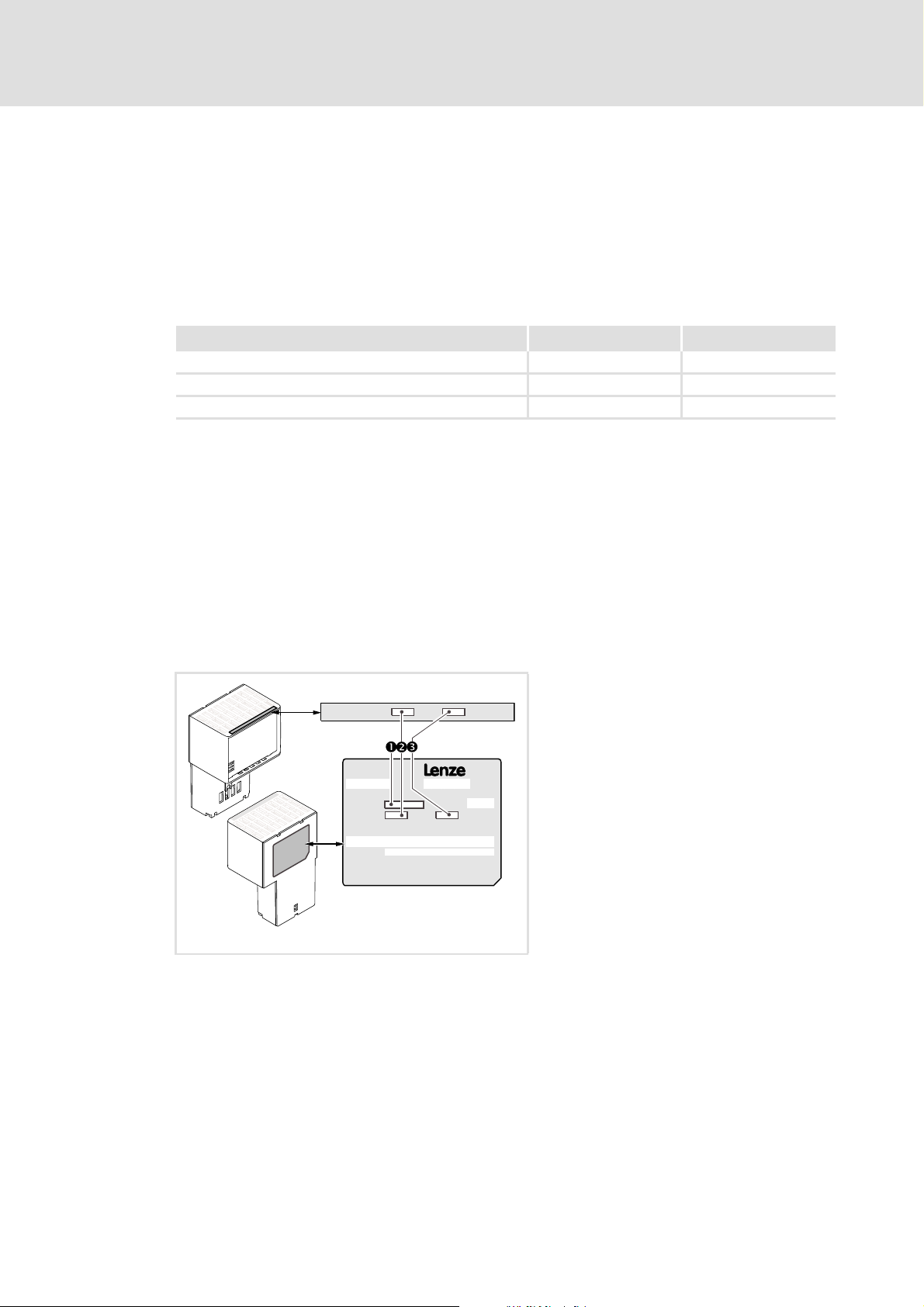
3.2 Identification
The type designation and the hardware and software versions of the communication
module are indicated on the nameplate:
[3-1] Identification data
8400
Type:
HW:
Ser.No.:
HW:
SW:
SW:
1 Type designation (type)
E84 Product series
AVersion
Y Module identification: Extension module
C Module type: Communication module
ER PROFINET
V/S V: Coated design
S: Standard design
2 Hardware version (HW)
3 Software version (SW)
E84YCPM001E
14 L EDS84AYCER EN 2.0 - 11/2010
3.3 Properties
Interface module for the PROFINET communication system to be secured to the
expansion slots of the Inverter Drives 8400
The communication module can either be supplied internally by the standard device or
externally by a separate voltage source.
Support of the I&M0...4 functionality for the identification of the standard device
Automatic detection of the baud rate 100 Mbps
A line topology is enabled by the integrated 2-port switch.
Support of the LLDP protocol for the topology recognition
Support of the SNMP protocol for diagnostic purposes
Access to all Lenze parameters
E84AYCER communication manual (PROFINET)
Product description
Properties
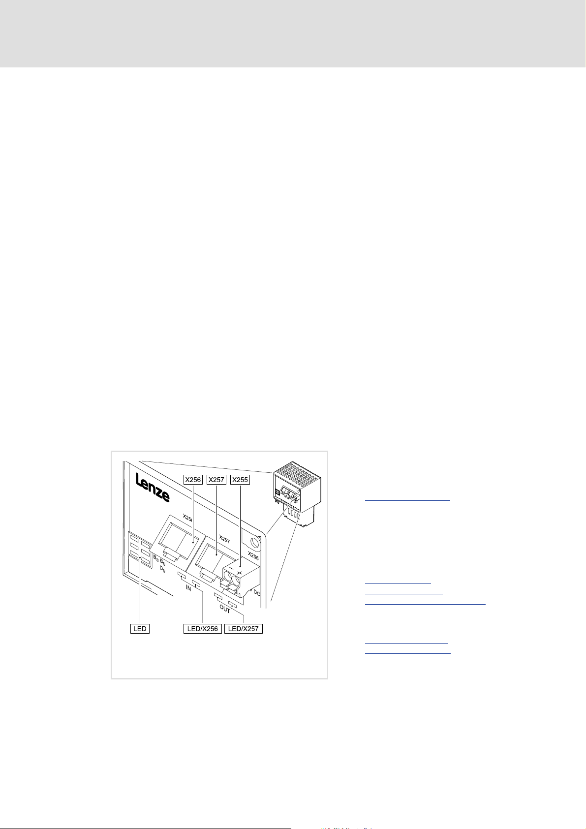
3.4 Terminals and interfaces
2 RJ45 sockets for the PROFINET connection
2-pole plug connector for the external voltage supply of the communication module.
Front LEDs for diagnosing the ...
– Voltage supply of the communication module;
– Connection to the standard device;
–PROFINET connection;
– PROFINET activity.
X255 External voltage supply of the communication
module
• 2-pole plug connector with spring
connection
External voltage supply
X256 PROFINET input (IN)
X257 PROFINET output (OUT)
• RJ45 sockets
• Each with 2 LED status displays for
diagnostics
Network topology
PROFINET connection
Status displays at X256 and X257
( 32)
( 26)
( 28)
( 69)
5 LED status displays for diagnostics
MS
Module status displays
E84YCER001C
[3-2] E84AYCER communication module (PROFINET)
EDS84AYCER EN 2.0 - 11/2010 L 15
ME
BS
Fieldbus status displays
BE
DE
( 67)
( 68)

E84AYCER communication manual (PROFINET)
Technical data
General data and operating conditions
4 Technical data
4.1 General data and operating conditions
Field Values
Order designation E84AYCER
Communication profile PROFINET
Communication medium S/FTP (Screened Foiled Twisted Pair, ISO/IEC 11801 or EN 50173), CAT 5e
Interface RJ45: Standard Ethernet (in accordance with IEEE 802.3), 100Base-TX (Fast
Network topology Tree, star, and line
Type of node IO device with real time (RT) communication properties
Number of device nodes Max. 255 in the subnetwork
Max. cable length 100 m
PUO ID number 0x0106
Device identification (Device ID) 0x8400
Baud rate 100 Mbps
Switching method "Store and forward"
Switch latency Approx. 125 μs at max. telegram length
Voltage supply External supply via separate power supply unit
Conformities, approvals • CE
Ethernet)
• "+": V = 24 V DC (20.4 V - 0 % ... 28.8 V + 0 %), I = 140 mA
• "-": Reference potential for external voltage supply
•UL
"Inverter Drives 8400" hardware manual
This manual contains data on ambient conditions and the electromagnetic
compatibility (EMC) that also apply to the communication module.
16 L EDS84AYCER EN 2.0 - 11/2010

4.2 Protective insulation
Danger!
Dangerous electrical voltage
If the Inverter Drives 8400 are used on a phase earthed mains with a rated mains
voltage ≥ 400 V, external measures need to be implemented in order to provide
reliable protection against accidental contact.
Possible consequences:
• Death or serious injury
Protective measures:
• If protection against accidental contact needs to be provided for the control
terminals of the controller and for the connections of the plugged-in device
modules, ...
– a double isolating distance must exist.
– the components to be connected must be provided with the second
isolating distance.
E84AYCER communication manual (PROFINET)
Technical data
Protective insulation
Note!
The protective insulation provided in the Inverter Drives 8400 is implemented in
accordance with EN 61800-5-1.
EDS84AYCER EN 2.0 - 11/2010 L 17
E84AYCER communication manual (PROFINET)
Technical data
Protective insulation
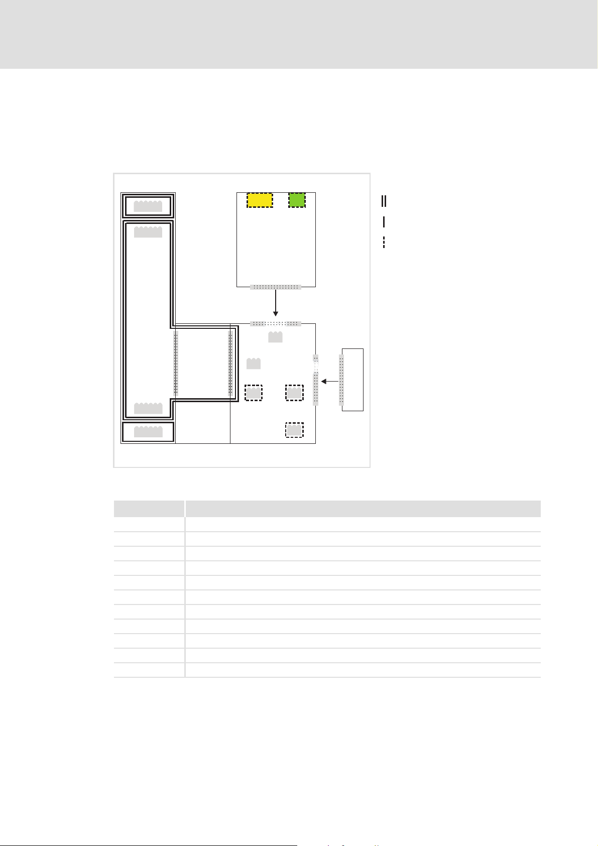
The illustration below ...
shows the arrangement of the terminal strips and the separate potential areas of the
Inverter Drive 8400.
serves to determine the decisive protective insulation between two terminals located
in differently insulated separate potential areas.
MCI
X6
X6
Ext. DC
X5
X5
X1X1
Bus
X106X106X106X101
X100X100
X3
X3
X4
X4
X105X105
X106X106X106X106
[4-1] Protective insulation in accordance with EN61800-5-1
Reinforced insulation
Basic insulation
Functional insulation
MMI
E84YCXX007
Terminal strip Connection
X100 Mains / DC-bus connection
X101 Relay contact
X105 Motor / brake resistor
X106 Motor PTC
X1 System bus (CANopen)
X3 Analog inputs / outputs
X4 Digital outputs
X5 Digital inputs
X6 Diagnostics
MCI Slot for communication module
MMI Slot for memory module
18 L EDS84AYCER EN 2.0 - 11/2010

Example
Which type of protective insulation is implemented between the bus terminal of the
device module in slot MCI and mains terminal X100?
The separate potential area with the better protective insulation is decisive.
– The separate potential area of the device module bus terminal is "functionally
insulated".
– The separate potential area of the mains terminal has a "reinforced insulation".
Result: The insulation between mains terminal X100 and the bus terminal is of the
"reinforced insulation" type.
4.3 Protocol data
Field Values
Process data words (PCD) Max. 16 process data words (max. 32 bytes)
Acyclic parameter data channel Limited by the PROFINET frame size
E84AYCER communication manual (PROFINET)
Technical data
Protocol data
4.4 Communication time
The communication time is the time between the start of a request and the arrival of the
corresponding response.
The communication times in the PROFINET network depend on the ...
Processing time inside the controller;
Telegram runtime (baud rate / telegram length);
Nesting depth of the network.
Processing time inside the controller
Data Processing time
Process data Approx. 2 ms
Parameter data Approx. 30 ms + a tolerance of 20 ms (typically)
There are no interdependencies between parameter data and process data.
Update cycle
+ 0 ... 1 ms
+ 1 ... x ms
• Some codes may require a longer processing time (see software manual/
»Engineer« online help for Inverter Drive 8400).
Processing time in the module
Runtime of the application task of the technology
application used (tolerance)
EDS84AYCER EN 2.0 - 11/2010 L 19

E84AYCER communication manual (PROFINET)
Technical data
Internal switch latency
4.5 Internal switch latency
The integrated 2 port switch causes runtime delays which can be calculated as follows:
Runtime delay = ((36 permanent bytes + process data in bytes) x 8 x 10 nsec) + 4 μsec
Example:
20 process data words + 4 PROFIsafe words => 48 bytes
((36 permanent bytes + 48 bytes) x 8 x 10 nsec) + 4 μsec
(84 bytes x 8 x 10 nsec) + 4 μsec
6.72 μsec + 4 μsec = 10.72 μsec
According to the PROFINET specification, the shortest PROFINET IO telegram must have a
data length of 72 bytes. If the 36 permanent bytes are subtracted from the 72 bytes, 36
bytes are available for process data. If now less than 36 bytes of process data are used, the
PROFINET IO telegram is filled with "zero bytes" until it can be transmitted. As a
consequence for the calculation formula, the shortest PROFINET IO telegram with 18
process data words (36 bytes) has always the same length and thus the runtime delay is
the same, too.
Note!
The use of external switches can also lead to runtime delays. Depending on the
system constellation, it may be useful to create a star topology or a line/mix
topology.
Network topology
( 26)
20 L EDS84AYCER EN 2.0 - 11/2010
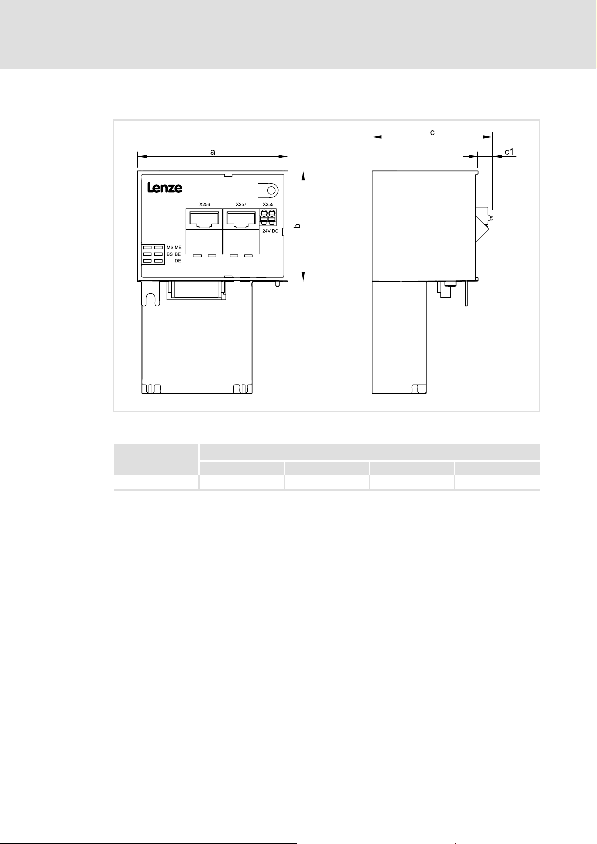
4.6 Dimensions
E84AYCER communication manual (PROFINET)
Technical data
Dimensions
[4-2] Dimensions
E84AYCER 67 50 57 8
E84YCER001B
Type Dimensions [mm]
a b c c1
EDS84AYCER EN 2.0 - 11/2010 L 21

E84AYCER communication manual (PROFINET)
Installation
5 Installation
Stop!
Electrostatic discharge
Electronic components within the communication module can be damaged or
destroyed by electrostatic discharge.
Possible consequences:
• The communication module is damaged.
• Fieldbus communication is not possible or is defective.
Protective measures:
• Release any electrostatic charge from your person before you touch the
module.
22 L EDS84AYCER EN 2.0 - 11/2010
E84AYCER communication manual (PROFINET)
5.1 Mechanical installation
When the controller is switched-on, the communication module can be plugged into the
MCI slot or removed from there. During the process of being plugged in, the module is
automatically detected and its functions and version are checked for plausibility.
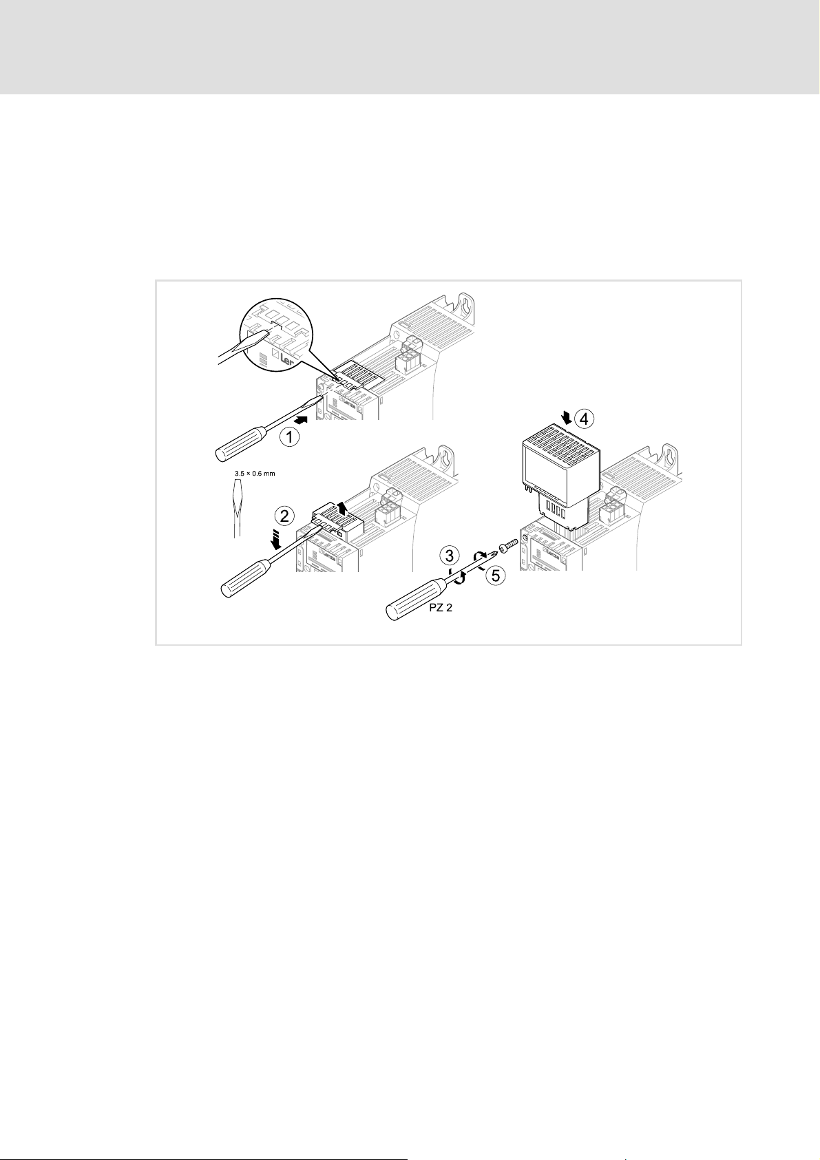
5.1.1 Mounting for standard devices 0.25 kW and 0.37 kW
Installation
Mechanical installation
[5-1] Mounting for standard devices 0.25 kW and 0.37 kW
Mounting steps
1. Use a screwdriver to open the cover of the MCI slot of the standard device and remove
it (1, 2).
2. Loosen the securing screw for the communication module on the standard device (3).
3. Insert the communication module into the MCI slot of the standard device (4).
4. Tighten the securing screw again (5).
E84YCPM002D
EDS84AYCER EN 2.0 - 11/2010 L 23
E84AYCER communication manual (PROFINET)
Installation
Mechanical installation
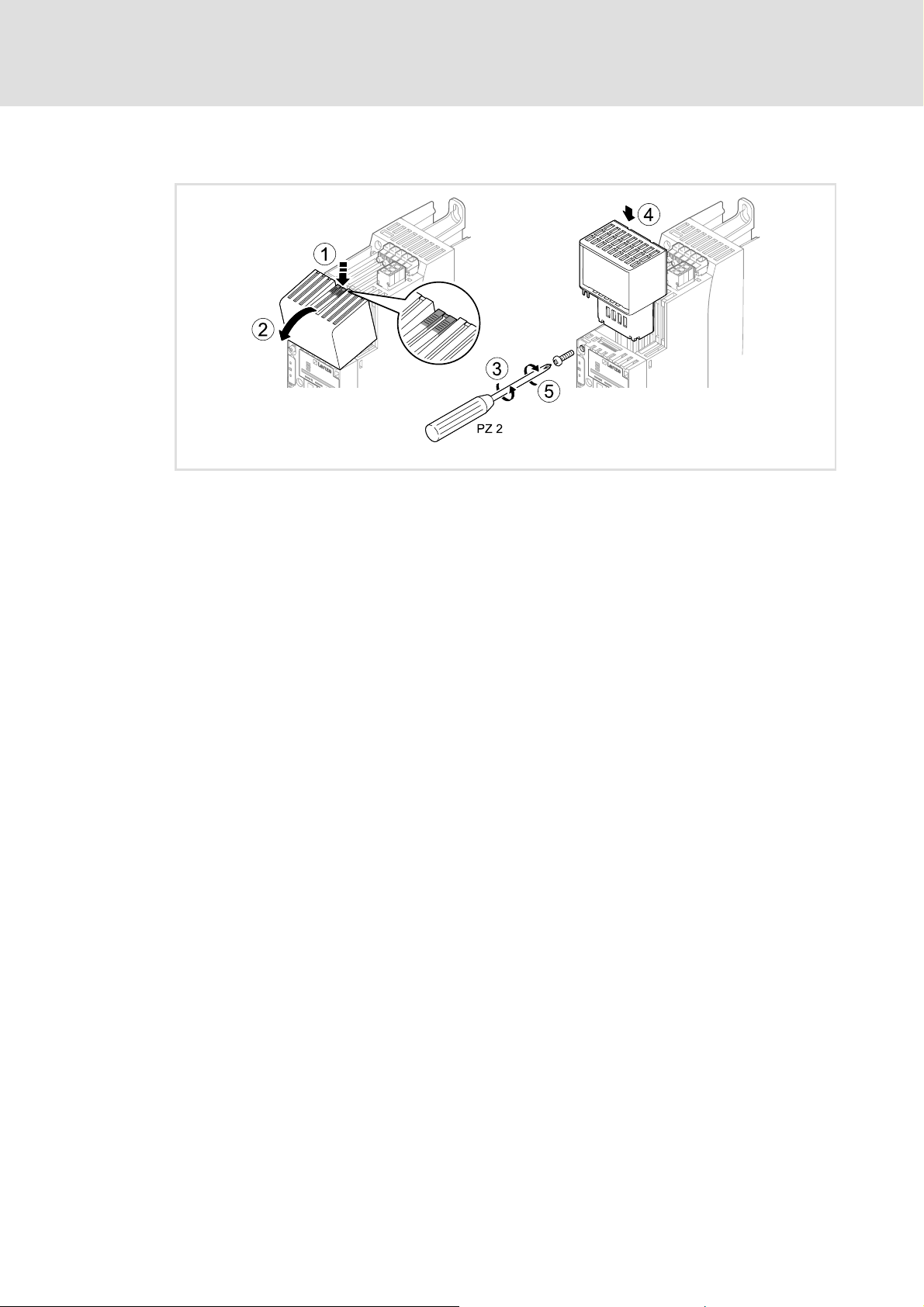
5.1.2 Mounting for standard devices from 0.55 kW
[5-2] Mounting for standard devices from 0.55 kW
E84YCPM002A
Mounting steps
1. Apply a little pressure on the surface of the top side of the standard device MCI slot
cover to leave an indentation (1).
2. Tilt the cover forwards and remove it from the standard device (2).
3. Loosen the securing screw for the communication module on the standard device (3).
4. Insert the communication module into the MCI slot of the standard device (4).
5. Tighten the securing screw again (5).
24 L EDS84AYCER EN 2.0 - 11/2010
E84AYCER communication manual (PROFINET)
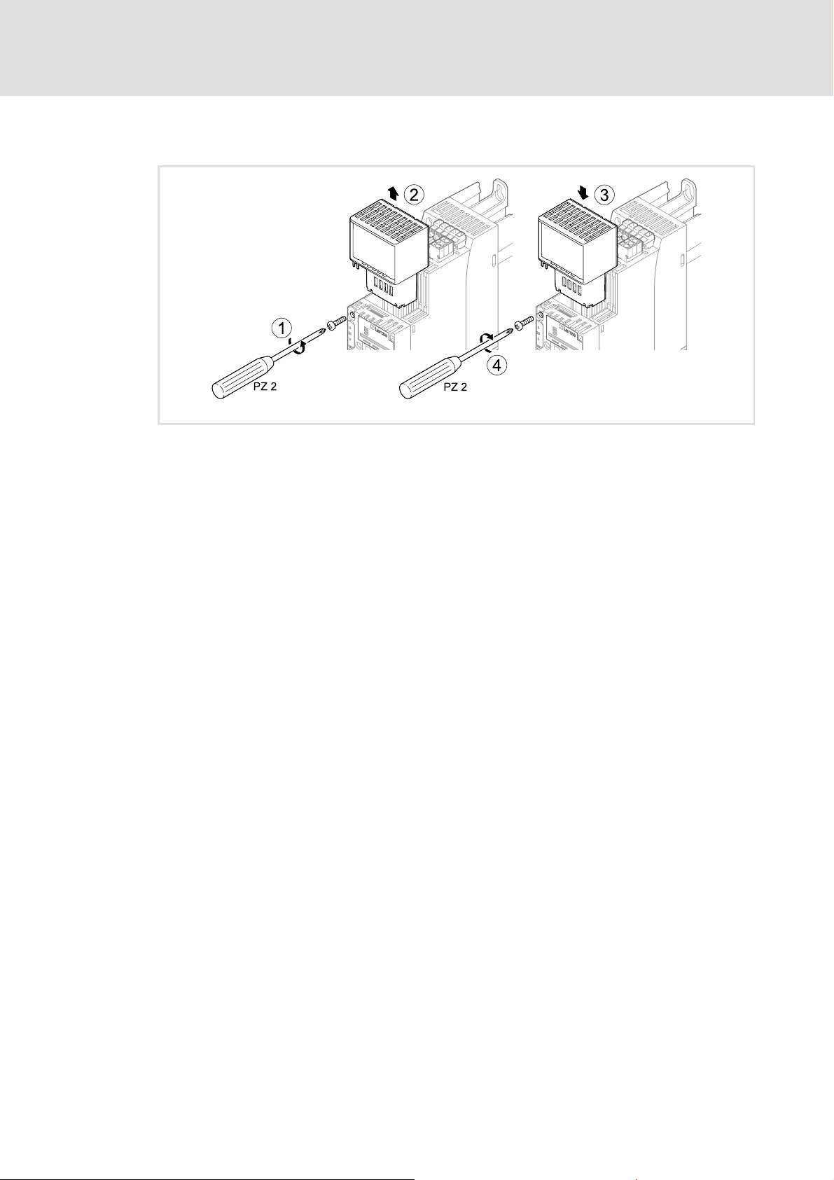
5.1.3 Replacing the communication module
[5-3] Replacing the communication module
Installation
Mechanical installation
E84YCPM002B
Mounting steps
1. Loosen the securing screw for the communication module on the standard device (1).
2. Unplug the communication module from the MCI slot of the standard device (2).
3. Insert the new communication module into the MCI slot of the standard device (3).
4. Tighten the securing screw again (4).
EDS84AYCER EN 2.0 - 11/2010 L 25
E84AYCER communication manual (PROFINET)
Installation
Electrical installation
5.2 Electrical installation
Documentation for the standard device, control system, plant/machine
Observe the notes and wiring instructions contained in this documentation.
5.2.1 EMC-compliant wiring
In typical systems, standard shielding is sufficient for Ethernet cables.
However, in environments with a very high level of interference, EMC resistance can be
improved by earthing the cable shield as well.
For this observe the following notes:
1. Remove the plastic sheath of the cable on a length of 2 cm.
2. Secure the cable shield to the shield connection of the standard device.
5.2.2 Network topology
It is typical for PROFINET to have a rather free topology the limiting factor of which is large
message latencies due to e.g. switches connected in series.
Internal switch latency
The combination of a line and a stub is useful for system wiring.
PROFINET supports the following topologies:
Switch / star
[5-4] Switch / star topology (S = switch, D = IO device)
( 20)
S
DD
D
E94YCER005
26 L EDS84AYCER EN 2.0 - 11/2010
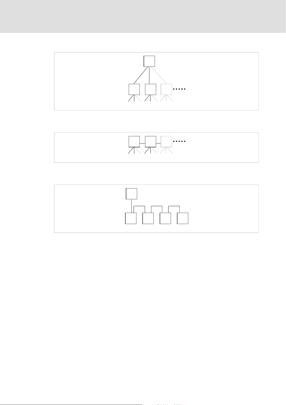
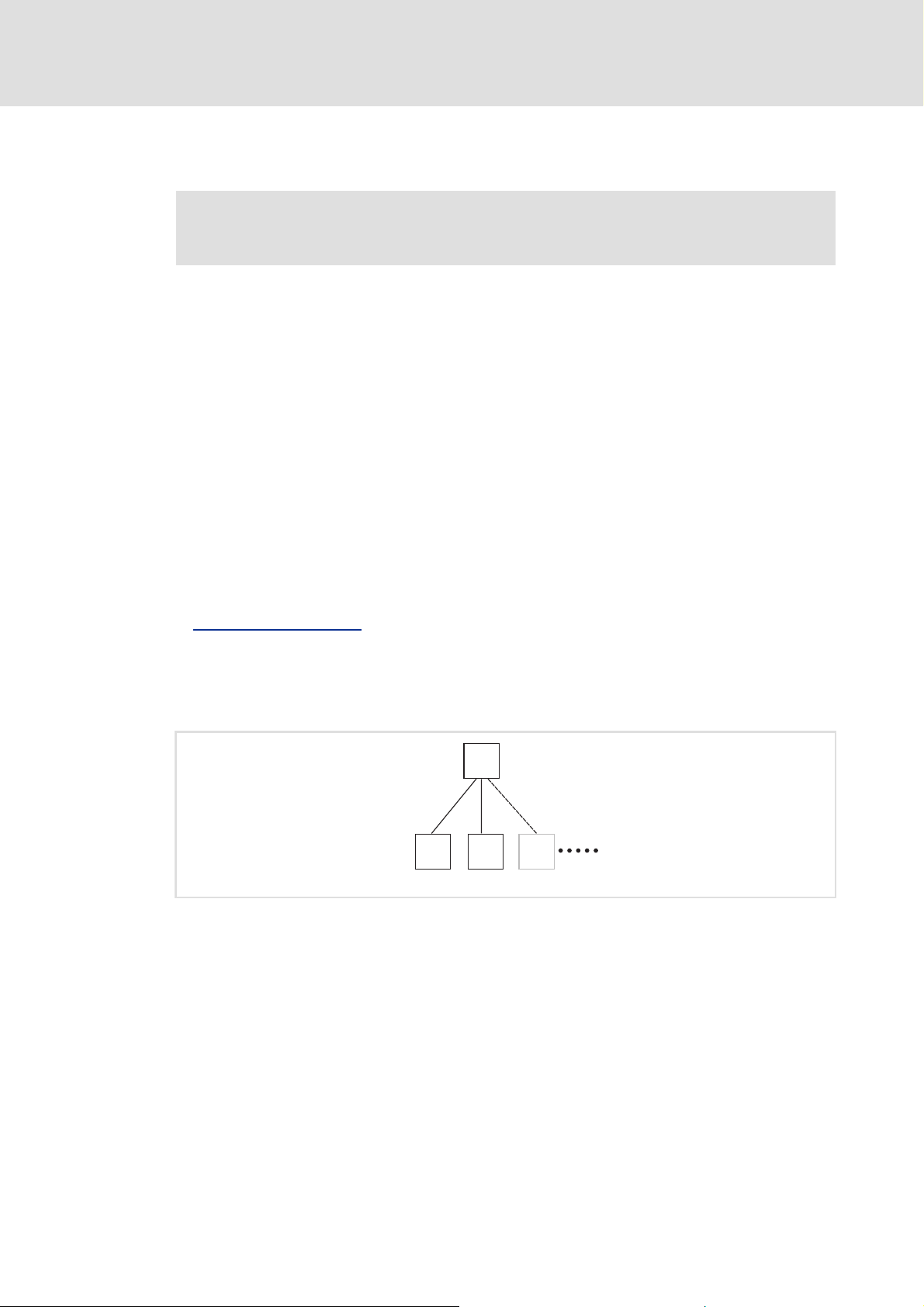
Tree via switches
E84AYCER communication manual (PROFINET)
Installation
Electrical installation
C
[5-5] Tree topology (C =IO controller, S = switch)
Switch / switch
[5-6] Switch/switch topology (S = switch)
IO controller / IO device
[5-7] Line topology (C = IO controller, D = IO device)
SS
S
SSS
C
D D D D
E94YCER006
E94YCER007
E94YCER008
EDS84AYCER EN 2.0 - 11/2010 L 27

E84AYCER communication manual (PROFINET)
Installation
Electrical installation
5.2.3 PROFINET connection
PROFINET is connected via RJ45 sockets X256 (input) and X257 (output).
[5-8] PROFINET connections X256 (IN) and X257 (OUT)
A standard Ethernet patch cable can be used for the connection to the communication
module.
Specification of the Ethernet cable
The installation and removal of the Ethernet cables is optimised for the use of connectors
in accordance with the "Automation Initiative of German Domestic Automobile
Manufacturers" (AIDA).
( 30)
Note!
To prevent the RJ45 socket from being damaged, hold the Ethernet cable
connector vertically when inserting it into or removing it from the socket.
E84YCER001E
28 L EDS84AYCER EN 2.0 - 11/2010

E84AYCER communication manual (PROFINET)
Pin assignment of the RJ45 sockets
RJ45 socket Pin Signal
1Tx +
2Tx -
3Rx +
4-
5-
6Rx -
E94AYCXX004C
7-
8-
Tip!
The PROFINET interfaces feature an auto MDIX function. This function adjusts the
polarity of the RJ45 interfaces so that a connection is established irrespective of the
polarity of the opposite PROFINET interface, and irrespecive of the type of cable
used (standard patch cable or crossover cable).
Installation
Electrical installation
EDS84AYCER EN 2.0 - 11/2010 L 29
Loading...