


 Loading...
Inverter
8400
Inverter Drives 8400 motec_ _ _ _ _ _ _ _ _ _ _
E84DGxxxx...
Reference manual |
EN |
|
|
Ä.Z>óä 13572994
L

Overview of technical documentation for Inverter Drives 8400
_ _ _ _ _ _ _ _ _ _ _ _ _ _ _ _ _ _ _ _ _ _ _ _ _ _ _ _ _ _ _ _ _ _ _ _ _ _ _ _ _ _ _ _ _ _ _ _ _ _ _ _ _ _ _ _ _ _ _ _ _ _ _ _
Project planning, selection & ordering |
|
Legend: |
|
8400 motec hardware manual |
|
Printed documentation |
|
Catalogue |
|
Online documentation |
|
|
|
|
(PDF/Engineer online help) |
|
|
|
|
|
|
|
|
Mounting & wiring |
|
Abbreviations used: |
|
MA 8400 motec |
|
BA |
Operating instructions |
MA for the accessories |
|
KHB |
Communication manual |
|
|
MA |
Mounting instructions |
|
|
||
|
|
|
|
Parameter setting |
|
SW |
Software/reference manual |
|
|
|
|
BA for diagnosis terminal |
|
|
|
SW 8400 motec |
This documentation |
||
KHB for communication unit |
|
|
|
|
|
|
|
|
|
|
|
Drive commissioning |
|
|
|
SW 8400 motec |
This documentation |
||
chapter "Commissioning"
chapter "Diagnostics & error management"
Networking
KHB for communication unitMA for the accessories
2 |
Lenze · 8400 motec · Reference manual · DMS 10.0 EN · 08/2019 · TD06 |
Contents
_ _ _ _ _ _ _ _ _ _ _ _ _ _ _ _ _ _ _ _ _ _ _ _ _ _ _ _ _ _ _ _ _ _ _ _ _ _ _ _ _ _ _ _ _ _ _ _ _ _ _ _ _ _ _ _ _ _ _ _ _ _ _ _
1 |
About this documentation _ _ _ _ _ _ _ _ _ _ _ _ _ _ _ _ _ _ _ _ _ _ _ _ _ _ _ _ _ _ _ _ _ _ _ _ _ _ _ |
12 |
||||||
1.1 |
Document history _ _ _ _ _ _ _ _ _ _ _ _ _ _ _ _ _ _ _ _ _ _ _ _ _ _ _ _ _ _ _ _ _ _ _ _ _ _ _ _ _ _ _ _ |
13 |
||||||
1.2 |
Conventions used |
_ _ _ _ _ _ _ _ _ _ _ _ _ _ _ _ _ _ _ _ _ _ _ _ _ _ _ _ _ _ _ _ _ _ _ _ _ _ _ _ _ _ _ _ |
14 |
|||||
1.3 |
Terminology used |
_ _ _ _ _ _ _ _ _ _ _ _ _ _ _ _ _ _ _ _ _ _ _ _ _ _ _ _ _ _ _ _ _ _ _ _ _ _ _ _ _ _ _ _ |
15 |
|||||
1.4 |
Definition of the notes used _ _ _ _ _ _ _ _ _ _ _ _ _ _ _ _ _ _ _ _ _ _ _ _ _ _ _ _ _ _ _ _ _ _ _ _ _ _ |
17 |
||||||
2 |
Introduction: Parameterising the inverter _ _ _ _ _ _ _ _ _ _ _ _ _ _ _ _ _ _ _ _ _ _ _ _ _ _ _ _ _ _ _ |
19 |
||||||
2.1 |
Integrated technology applications |
_ _ _ _ _ _ _ _ _ _ _ _ _ _ _ _ _ _ _ _ _ _ _ _ _ _ _ _ _ _ _ _ _ _ |
21 |
|||||
2.2 |
Selection of the appropriate commissioning tool _ _ _ _ _ _ _ _ _ _ _ _ _ _ _ _ _ _ _ _ _ _ _ _ _ _ _ |
22 |
||||||
|
2.2.1 |
Overview: Accessories for commissioning |
_ _ _ _ _ _ _ _ _ _ _ _ _ _ _ _ _ _ _ _ _ _ _ _ _ _ |
23 |
||||
2.3 |
General notes on parameters _ _ _ _ _ _ _ _ _ _ _ _ _ _ _ _ _ _ _ _ _ _ _ _ _ _ _ _ _ _ _ _ _ _ _ _ _ _ |
24 |
||||||
|
2.3.1 |
Changing the parameterisation with the keypad |
_ _ _ _ _ _ _ _ _ _ _ _ _ _ _ _ _ _ _ _ _ _ |
25 |
||||
|
2.3.2 |
Change parameter settings with PC and Lenze software _ _ _ _ _ _ _ _ _ _ _ _ _ _ _ _ _ _ |
28 |
|||||
|
2.3.3 |
User menu for quick access to frequently used parameters _ _ _ _ _ _ _ _ _ _ _ _ _ _ _ _ _ |
29 |
|||||
2.4 |
Handling the memory module _ _ _ _ _ _ _ _ _ _ _ _ _ _ _ _ _ _ _ _ _ _ _ _ _ _ _ _ _ _ _ _ _ _ _ _ _ |
30 |
||||||
2.5 |
Device identification _ _ _ _ _ _ _ _ _ _ _ _ _ _ _ _ _ _ _ _ _ _ _ _ _ _ _ _ _ _ _ _ _ _ _ _ _ _ _ _ _ _ |
32 |
||||||
|
2.5.1 |
Automatic acceptance of the device name in the »Engineer« _ _ _ _ _ _ _ _ _ _ _ _ _ _ _ _ |
32 |
|||||
3 |
Commissioning _ _ _ _ _ _ _ _ _ _ _ _ _ _ _ _ _ _ _ _ _ _ _ _ _ _ _ _ _ _ _ _ _ _ _ _ _ _ _ _ _ _ _ _ _ |
33 |
||||||
3.1 |
Safety instructions with regard to commissioning |
_ _ _ _ _ _ _ _ _ _ _ _ _ _ _ _ _ _ _ _ _ _ _ _ _ _ |
34 |
|||||
3.2 |
Preconditions for commissioning with the »Engineer« _ _ _ _ _ _ _ _ _ _ _ _ _ _ _ _ _ _ _ _ _ _ _ _ |
35 |
||||||
3.3 |
Trouble-shooting during commissioning _ _ _ _ _ _ _ _ _ _ _ _ _ _ _ _ _ _ _ _ _ _ _ _ _ _ _ _ _ _ _ |
35 |
||||||
3.4 |
Commissioning wizard 8400 _ _ _ _ _ _ _ _ _ _ _ _ _ _ _ _ _ _ _ _ _ _ _ _ _ _ _ _ _ _ _ _ _ _ _ _ _ _ |
36 |
||||||
3.5 |
Commissioning of the "Actuating drive speed" technology application _ _ _ _ _ _ _ _ _ _ _ _ _ _ _ |
37 |
||||||
|
3.5.1 |
Prepare inverter for commissioning |
_ _ _ _ _ _ _ _ _ _ _ _ _ _ _ _ _ _ _ _ _ _ _ _ _ _ _ _ _ |
38 |
||||
|
3.5.2 |
Creating an »Engineer« project & going online |
_ _ _ _ _ _ _ _ _ _ _ _ _ _ _ _ _ _ _ _ _ _ _ |
39 |
||||
|
3.5.3 |
Parameterising the motor control |
_ _ _ _ _ _ _ _ _ _ _ _ _ _ _ _ _ _ _ _ _ _ _ _ _ _ _ _ _ _ |
40 |
||||
|
3.5.4 |
Parameterise application |
_ _ _ _ _ _ _ _ _ _ _ _ _ _ _ _ _ _ _ _ _ _ _ _ _ _ _ _ _ _ _ _ _ _ _ |
42 |
||||
|
3.5.5 |
Save parameter settings safe against mains failure _ _ _ _ _ _ _ _ _ _ _ _ _ _ _ _ _ _ _ _ _ |
44 |
|||||
|
3.5.6 |
Enabling the inverter and selecting the speed _ _ _ _ _ _ _ _ _ _ _ _ _ _ _ _ _ _ _ _ _ _ _ _ |
44 |
|||||
3.6 |
Commissioning of the "Switch-off positioning" technology application _ _ _ _ _ _ _ _ _ _ _ _ _ _ _ |
45 |
||||||
|
3.6.1 |
Prepare inverter for commissioning |
_ _ _ _ _ _ _ _ _ _ _ _ _ _ _ _ _ _ _ _ _ _ _ _ _ _ _ _ _ |
47 |
||||
|
3.6.2 |
Creating an »Engineer« project & going online |
_ _ _ _ _ _ _ _ _ _ _ _ _ _ _ _ _ _ _ _ _ _ _ |
48 |
||||
|
3.6.3 |
Parameterising the motor control |
_ _ _ _ _ _ _ _ _ _ _ _ _ _ _ _ _ _ _ _ _ _ _ _ _ _ _ _ _ _ |
49 |
||||
|
3.6.4 |
Parameterise application |
_ _ _ _ _ _ _ _ _ _ _ _ _ _ _ _ _ _ _ _ _ _ _ _ _ _ _ _ _ _ _ _ _ _ _ |
51 |
||||
|
3.6.5 |
Save parameter settings safe against mains failure _ _ _ _ _ _ _ _ _ _ _ _ _ _ _ _ _ _ _ _ _ |
53 |
|||||
|
3.6.6 |
Enable inverter and test application |
_ _ _ _ _ _ _ _ _ _ _ _ _ _ _ _ _ _ _ _ _ _ _ _ _ _ _ _ _ |
53 |
||||
3.7 |
PC manual control _ _ _ _ _ _ _ _ _ _ _ _ _ _ _ _ _ _ _ _ _ _ _ _ _ _ _ _ _ _ _ _ _ _ _ _ _ _ _ _ _ _ _ _ |
54 |
||||||
3.8 |
Control via Field Package ("key-operated switch operation") _ _ _ _ _ _ _ _ _ _ _ _ _ _ _ _ _ _ _ _ _ |
58 |
||||||
Lenze · 8400 motec · Reference manual · DMS 10.0 EN · 08/2019 · TD06 |
3 |
Contents
_ _ _ _ _ _ _ _ _ _ _ _ _ _ _ _ _ _ _ _ _ _ _ _ _ _ _ _ _ _ _ _ _ _ _ _ _ _ _ _ _ _ _ _ _ _ _ _ _ _ _ _ _ _ _ _ _ _ _ _ _ _ _ _
4 |
Device control (DCTRL) |
_ _ _ _ _ _ _ _ _ _ _ _ _ _ _ _ _ _ _ _ _ _ _ _ _ _ _ _ _ _ _ _ _ _ _ _ _ _ _ _ _ |
61 |
|||
4.1 |
Device commands (C00002/x) _ _ _ _ _ _ _ _ _ _ _ _ _ _ _ _ _ _ _ _ _ _ _ _ _ _ _ _ _ _ _ _ _ _ _ _ _ |
63 |
||||
|
4.1.1 |
Load Lenze setting _ _ _ _ _ _ _ _ _ _ _ _ _ _ _ _ _ _ _ _ _ _ _ _ _ _ _ _ _ _ _ _ _ _ _ _ _ _ _ |
65 |
|||
|
4.1.2 |
Load parameter set 1 _ _ _ _ _ _ _ _ _ _ _ _ _ _ _ _ _ _ _ _ _ _ _ _ _ _ _ _ _ _ _ _ _ _ _ _ _ |
66 |
|||
|
4.1.3 |
Save parameter settings _ _ _ _ _ _ _ _ _ _ _ _ _ _ _ _ _ _ _ _ _ _ _ _ _ _ _ _ _ _ _ _ _ _ _ _ |
67 |
|||
|
4.1.4 |
Import EPM data _ _ _ _ _ _ _ _ _ _ _ _ _ _ _ _ _ _ _ _ _ _ _ _ _ _ _ _ _ _ _ _ _ _ _ _ _ _ _ _ |
67 |
|||
|
4.1.5 |
Enable/inhibit inverter _ _ _ _ _ _ _ _ _ _ _ _ _ _ _ _ _ _ _ _ _ _ _ _ _ _ _ _ _ _ _ _ _ _ _ _ _ |
68 |
|||
|
4.1.6 |
Activate/deactivate quick stop _ _ _ _ _ _ _ _ _ _ _ _ _ _ _ _ _ _ _ _ _ _ _ _ _ _ _ _ _ _ _ _ |
68 |
|||
|
4.1.7 |
Reset error |
_ _ _ _ _ _ _ _ _ _ _ _ _ _ _ _ _ _ _ _ _ _ _ _ _ _ _ _ _ _ _ _ _ _ _ _ _ _ _ _ _ _ _ |
69 |
||
|
4.1.8 |
Delete logbook _ _ _ _ _ _ _ _ _ _ _ _ _ _ _ _ _ _ _ _ _ _ _ _ _ _ _ _ _ _ _ _ _ _ _ _ _ _ _ _ _ |
69 |
|||
|
4.1.9 |
Identify motor parameters _ _ _ _ _ _ _ _ _ _ _ _ _ _ _ _ _ _ _ _ _ _ _ _ _ _ _ _ _ _ _ _ _ _ |
70 |
|||
|
4.1.10 |
CAN reset node _ _ _ _ _ _ _ _ _ _ _ _ _ _ _ _ _ _ _ _ _ _ _ _ _ _ _ _ _ _ _ _ _ _ _ _ _ _ _ _ _ |
70 |
|||
|
4.1.11 |
Device search function _ _ _ _ _ _ _ _ _ _ _ _ _ _ _ _ _ _ _ _ _ _ _ _ _ _ _ _ _ _ _ _ _ _ _ _ _ |
71 |
|||
4.2 |
Device state machine and device states _ _ _ _ _ _ _ _ _ _ _ _ _ _ _ _ _ _ _ _ _ _ _ _ _ _ _ _ _ _ _ _ |
72 |
||||
|
4.2.1 |
Init |
_ _ _ _ _ _ _ _ _ _ _ _ _ _ _ _ _ _ _ _ _ _ _ _ _ _ _ _ _ _ _ _ _ _ _ _ _ _ _ _ _ _ _ _ _ _ _ |
74 |
||
|
4.2.2 |
MotorIdent _ _ _ _ _ _ _ _ _ _ _ _ _ _ _ _ _ _ _ _ _ _ _ _ _ _ _ _ _ _ _ _ _ _ _ _ _ _ _ _ _ _ _ |
75 |
|||
|
4.2.3 |
SafeTorqueOff |
_ _ _ _ _ _ _ _ _ _ _ _ _ _ _ _ _ _ _ _ _ _ _ _ _ _ _ _ _ _ _ _ _ _ _ _ _ _ _ _ _ |
75 |
||
|
4.2.4 |
ReadyToSwitchOn _ _ _ _ _ _ _ _ _ _ _ _ _ _ _ _ _ _ _ _ _ _ _ _ _ _ _ _ _ _ _ _ _ _ _ _ _ _ _ |
76 |
|||
|
4.2.5 |
SwitchedOn |
_ _ _ _ _ _ _ _ _ _ _ _ _ _ _ _ _ _ _ _ _ _ _ _ _ _ _ _ _ _ _ _ _ _ _ _ _ _ _ _ _ _ |
77 |
||
|
4.2.6 |
OperationEnabled _ _ _ _ _ _ _ _ _ _ _ _ _ _ _ _ _ _ _ _ _ _ _ _ _ _ _ _ _ _ _ _ _ _ _ _ _ _ _ |
78 |
|||
|
4.2.7 |
Trouble _ _ _ _ _ _ _ _ _ _ _ _ _ _ _ _ _ _ _ _ _ _ _ _ _ _ _ _ _ _ _ _ _ _ _ _ _ _ _ _ _ _ _ _ _ |
79 |
|||
|
4.2.8 |
Fault |
_ _ _ _ _ _ _ _ _ _ _ _ _ _ _ _ _ _ _ _ _ _ _ _ _ _ _ _ _ _ _ _ _ _ _ _ _ _ _ _ _ _ _ _ _ _ |
80 |
||
4.3 |
Auto-start option "Inhibit at power-on" _ _ _ _ _ _ _ _ _ _ _ _ _ _ _ _ _ _ _ _ _ _ _ _ _ _ _ _ _ _ _ _ |
81 |
||||
4.4 |
Energy saving mode _ _ _ _ _ _ _ _ _ _ _ _ _ _ _ _ _ _ _ _ _ _ _ _ _ _ _ _ _ _ _ _ _ _ _ _ _ _ _ _ _ _ _ |
83 |
||||
4 |
Lenze · 8400 motec · Reference manual · DMS 10.0 EN · 08/2019 · TD06 |
Contents
_ _ _ _ _ _ _ _ _ _ _ _ _ _ _ _ _ _ _ _ _ _ _ _ _ _ _ _ _ _ _ _ _ _ _ _ _ _ _ _ _ _ _ _ _ _ _ _ _ _ _ _ _ _ _ _ _ _ _ _ _ _ _ _
5 |
Motor control (MCTRL) |
_ _ _ _ _ _ _ _ _ _ _ _ _ _ _ _ _ _ _ _ _ _ _ _ _ _ _ _ _ _ _ _ _ _ _ _ _ _ _ _ _ |
85 |
|||||||
5.1 |
Special features of the 8400 motec _ _ _ _ _ _ _ _ _ _ _ _ _ _ _ _ _ _ _ _ _ _ _ _ _ _ _ _ _ _ _ _ _ _ _ |
86 |
||||||||
5.2 |
Motor selection/Motor data |
_ _ _ _ _ _ _ _ _ _ _ _ _ _ _ _ _ _ _ _ _ _ _ _ _ _ _ _ _ _ _ _ _ _ _ _ _ _ |
87 |
|||||||
|
5.2.1 |
Selecting a motor from the motor catalogue in the »Engineer« _ _ _ _ _ _ _ _ _ _ _ _ _ _ |
93 |
|||||||
|
5.2.2 |
Automatic motor data identification _ _ _ _ _ _ _ _ _ _ _ _ _ _ _ _ _ _ _ _ _ _ _ _ _ _ _ _ _ |
95 |
|||||||
5.3 |
Selecting the control mode |
_ _ _ _ _ _ _ _ _ _ _ _ _ _ _ _ _ _ _ _ _ _ _ _ _ _ _ _ _ _ _ _ _ _ _ _ _ _ _ |
97 |
|||||||
|
5.3.1 |
Selection help |
_ _ _ _ _ _ _ _ _ _ _ _ _ _ _ _ _ _ _ _ _ _ _ _ _ _ _ _ _ _ _ _ _ _ _ _ _ _ _ _ _ |
100 |
||||||
5.4 |
Defining current and speed limits |
_ _ _ _ _ _ _ _ _ _ _ _ _ _ _ _ _ _ _ _ _ _ _ _ _ _ _ _ _ _ _ _ _ _ _ |
101 |
|||||||
5.5 |
V/f characteristic control (VFCplus) _ _ _ _ _ _ _ _ _ _ _ _ _ _ _ _ _ _ _ _ _ _ _ _ _ _ _ _ _ _ _ _ _ _ _ |
103 |
||||||||
|
5.5.1 |
Parameterisation dialog/signal flow _ _ _ _ _ _ _ _ _ _ _ _ _ _ _ _ _ _ _ _ _ _ _ _ _ _ _ _ _ |
103 |
|||||||
|
5.5.2 |
Basic settings _ _ _ _ _ _ _ _ _ _ _ _ _ _ _ _ _ _ _ _ _ _ _ _ _ _ _ _ _ _ _ _ _ _ _ _ _ _ _ _ _ _ |
105 |
|||||||
|
|
5.5.2.1 |
Define V/f characteristic shape _ _ _ _ _ _ _ _ _ _ _ _ _ _ _ _ _ _ _ _ _ _ _ _ _ _ |
105 |
||||||
|
|
5.5.2.2 |
Defining current limits (Imax controller) _ _ _ _ _ _ _ _ _ _ _ _ _ _ _ _ _ _ _ _ _ |
106 |
||||||
|
5.5.3 |
Optimising the control mode _ _ _ _ _ _ _ _ _ _ _ _ _ _ _ _ _ _ _ _ _ _ _ _ _ _ _ _ _ _ _ _ _ |
107 |
|||||||
|
|
5.5.3.1 |
Adapting the V/f base frequency _ _ _ _ _ _ _ _ _ _ _ _ _ _ _ _ _ _ _ _ _ _ _ _ _ |
108 |
||||||
|
|
5.5.3.2 |
Adapting the Vmin boost _ _ _ _ _ _ _ _ _ _ _ _ _ _ _ _ _ _ _ _ _ _ _ _ _ _ _ _ _ |
109 |
||||||
|
|
5.5.3.3 |
Optimising the Imax controller _ _ _ _ _ _ _ _ _ _ _ _ _ _ _ _ _ _ _ _ _ _ _ _ _ _ |
110 |
||||||
|
|
5.5.3.4 |
Torque limitation _ _ _ _ _ _ _ _ _ _ _ _ _ _ _ _ _ _ _ _ _ _ _ _ _ _ _ _ _ _ _ _ _ |
111 |
||||||
|
|
5.5.3.5 |
Optimising the starting performance after a controller enable |
_ _ _ _ _ _ _ _ |
112 |
|||||
|
5.5.4 |
Remedies for undesired drive behaviour _ _ _ _ _ _ _ _ _ _ _ _ _ _ _ _ _ _ _ _ _ _ _ _ _ _ _ |
113 |
|||||||
5.6 |
V/f characteristic control - energy-saving (VFCplusEco) _ _ _ _ _ _ _ _ _ _ _ _ _ _ _ _ _ _ _ _ _ _ _ _ |
114 |
||||||||
|
5.6.1 |
Parameterisation dialog/signal flow _ _ _ _ _ _ _ _ _ _ _ _ _ _ _ _ _ _ _ _ _ _ _ _ _ _ _ _ _ |
115 |
|||||||
|
5.6.2 |
Comparison of VFCplusEco - VFCplus _ _ _ _ _ _ _ _ _ _ _ _ _ _ _ _ _ _ _ _ _ _ _ _ _ _ _ _ _ |
117 |
|||||||
|
5.6.3 |
Basic settings _ _ _ _ _ _ _ _ _ _ _ _ _ _ _ _ _ _ _ _ _ _ _ _ _ _ _ _ _ _ _ _ _ _ _ _ _ _ _ _ _ _ |
118 |
|||||||
|
5.6.4 |
Optimising the control mode _ _ _ _ _ _ _ _ _ _ _ _ _ _ _ _ _ _ _ _ _ _ _ _ _ _ _ _ _ _ _ _ _ |
119 |
|||||||
|
|
5.6.4.1 |
Improving the behaviour at high dynamic load changes _ _ _ _ _ _ _ _ _ _ _ _ |
120 |
||||||
|
|
5.6.4.2 |
Adapting the slope limitation for lowering the Eco function _ _ _ _ _ _ _ _ _ _ |
120 |
||||||
|
|
5.6.4.3 |
Optimising the cos/phi controller |
_ _ _ _ _ _ _ _ _ _ _ _ _ _ _ _ _ _ _ _ _ _ _ _ |
121 |
|||||
|
|
5.6.4.4 |
Optimising the starting performance after a controller enable |
_ _ _ _ _ _ _ _ |
122 |
|||||
|
5.6.5 |
Remedies for undesired drive behaviour _ _ _ _ _ _ _ _ _ _ _ _ _ _ _ _ _ _ _ _ _ _ _ _ _ _ _ |
123 |
|||||||
5.7 |
V/f control (VFCplus + encoder) _ _ _ _ _ _ _ _ _ _ _ _ _ _ _ _ _ _ _ _ _ _ _ _ _ _ _ _ _ _ _ _ _ _ _ _ _ |
124 |
||||||||
|
5.7.1 |
Parameterisation dialog/signal flow _ _ _ _ _ _ _ _ _ _ _ _ _ _ _ _ _ _ _ _ _ _ _ _ _ _ _ _ _ |
125 |
|||||||
|
5.7.2 |
Basic settings _ _ _ _ _ _ _ _ _ _ _ _ _ _ _ _ _ _ _ _ _ _ _ _ _ _ _ _ _ _ _ _ _ _ _ _ _ _ _ _ _ _ |
127 |
|||||||
|
|
5.7.2.1 |
Define V/f characteristic shape _ _ _ _ _ _ _ _ _ _ _ _ _ _ _ _ _ _ _ _ _ _ _ _ _ _ |
128 |
||||||
|
|
5.7.2.2 |
Defining current limits (Imax controller) _ _ _ _ _ _ _ _ _ _ _ _ _ _ _ _ _ _ _ _ _ |
129 |
||||||
|
|
5.7.2.3 |
Parameterising the slip regulator _ _ _ _ _ _ _ _ _ _ _ _ _ _ _ _ _ _ _ _ _ _ _ _ _ |
130 |
||||||
|
5.7.3 |
Optimising the control mode _ _ _ _ _ _ _ _ _ _ _ _ _ _ _ _ _ _ _ _ _ _ _ _ _ _ _ _ _ _ _ _ _ |
134 |
|||||||
|
|
5.7.3.1 |
Optimising the starting performance after a controller enable |
_ _ _ _ _ _ _ _ |
134 |
|||||
5.8 |
Sensorless vector control (SLVC) |
_ _ _ _ _ _ _ _ _ _ _ _ _ _ _ _ _ _ _ _ _ _ _ _ _ _ _ _ _ _ _ _ _ _ _ _ |
135 |
|||||||
|
5.8.1 |
Parameterisation dialog _ _ _ _ _ _ _ _ _ _ _ _ _ _ _ _ _ _ _ _ _ _ _ _ _ _ _ _ _ _ _ _ _ _ _ _ |
136 |
|||||||
|
5.8.2 |
Types of control |
_ _ _ _ _ _ _ _ _ _ _ _ _ _ _ _ _ _ _ _ _ _ _ _ _ _ _ _ _ _ _ _ _ _ _ _ _ _ _ _ |
137 |
||||||
|
|
5.8.2.1 |
Speed control with torque limitation |
_ _ _ _ _ _ _ _ _ _ _ _ _ _ _ _ _ _ _ _ _ _ |
138 |
|||||
|
|
5.8.2.2 |
Torque control with speed limitation |
_ _ _ _ _ _ _ _ _ _ _ _ _ _ _ _ _ _ _ _ _ _ |
139 |
|||||
|
5.8.3 |
Basic settings _ _ _ _ _ _ _ _ _ _ _ _ _ _ _ _ _ _ _ _ _ _ _ _ _ _ _ _ _ _ _ _ _ _ _ _ _ _ _ _ _ _ |
141 |
|||||||
|
|
5.8.3.1 |
Reduction of the speed overshoot |
_ _ _ _ _ _ _ _ _ _ _ _ _ _ _ _ _ _ _ _ _ _ _ _ |
142 |
|||||
|
5.8.4 |
Optimising the control mode _ _ _ _ _ _ _ _ _ _ _ _ _ _ _ _ _ _ _ _ _ _ _ _ _ _ _ _ _ _ _ _ _ |
143 |
|||||||
|
|
5.8.4.1 |
Optimising the starting performance after a controller enable |
_ _ _ _ _ _ _ _ |
143 |
|||||
|
5.8.5 |
Remedies for undesired drive behaviour _ _ _ _ _ _ _ _ _ _ _ _ _ _ _ _ _ _ _ _ _ _ _ _ _ _ _ |
144 |
|||||||
Lenze · 8400 motec · Reference manual · DMS 10.0 EN · 08/2019 · TD06 |
5 |
Contents
_ _ _ _ _ _ _ _ _ _ _ _ _ _ _ _ _ _ _ _ _ _ _ _ _ _ _ _ _ _ _ _ _ _ _ _ _ _ _ _ _ _ _ _ _ _ _ _ _ _ _ _ _ _ _ _ _ _ _ _ _ _ _ _
5.9 |
Sensorless control for synchronous motors (SLPSM) |
_ _ _ _ _ _ _ _ _ _ _ _ _ _ _ _ _ _ _ _ _ _ _ _ _ |
145 |
|||||||
|
5.9.1 |
Parameterisation dialog/signal flow _ _ _ _ _ _ _ _ _ _ _ _ _ _ _ _ _ _ _ _ _ _ _ _ _ _ _ _ _ |
148 |
|||||||
|
5.9.2 |
Increasing the acceleration of the drive |
_ _ _ _ _ _ _ _ _ _ _ _ _ _ _ _ _ _ _ _ _ _ _ _ _ _ _ |
151 |
||||||
|
5.9.3 |
Types of control _ _ _ _ _ _ _ _ _ _ _ _ _ _ _ _ _ _ _ _ _ _ _ _ _ _ _ _ _ _ _ _ _ _ _ _ _ _ _ _ |
151 |
|||||||
|
5.9.4 |
Basic settings _ _ _ _ _ _ _ _ _ _ _ _ _ _ _ _ _ _ _ _ _ _ _ _ _ _ _ _ _ _ _ _ _ _ _ _ _ _ _ _ _ _ |
153 |
|||||||
|
5.9.5 |
Optimising the control mode |
_ _ _ _ _ _ _ _ _ _ _ _ _ _ _ _ _ _ _ _ _ _ _ _ _ _ _ _ _ _ _ _ _ |
154 |
||||||
|
|
5.9.5.1 |
Optimise current controller _ _ _ _ _ _ _ _ _ _ _ _ _ _ _ _ _ _ _ _ _ _ _ _ _ _ _ _ |
155 |
||||||
|
|
5.9.5.2 |
Optimise speed controller _ _ _ _ _ _ _ _ _ _ _ _ _ _ _ _ _ _ _ _ _ _ _ _ _ _ _ _ _ |
155 |
||||||
|
|
5.9.5.3 |
Current-dependent stator leakage inductance Ppp(I) _ _ _ _ _ _ _ _ _ _ _ _ _ _ |
159 |
||||||
|
|
5.9.5.4 |
Optimising the starting performance after a controller enable |
_ _ _ _ _ _ _ _ |
161 |
|||||
|
5.9.6 |
Pole position identification without motion _ _ _ _ _ _ _ _ _ _ _ _ _ _ _ _ _ _ _ _ _ _ _ _ _ |
162 |
|||||||
|
5.9.7 |
Field weakening for synchronous motors |
_ _ _ _ _ _ _ _ _ _ _ _ _ _ _ _ _ _ _ _ _ _ _ _ _ _ |
164 |
||||||
5.10 |
Parameterisable additional functions |
_ _ _ _ _ _ _ _ _ _ _ _ _ _ _ _ _ _ _ _ _ _ _ _ _ _ _ _ _ _ _ _ _ |
168 |
|||||||
|
5.10.1 |
Selection of switching frequency |
_ _ _ _ _ _ _ _ _ _ _ _ _ _ _ _ _ _ _ _ _ _ _ _ _ _ _ _ _ _ _ |
168 |
||||||
|
5.10.2 |
Flying restart function _ _ _ _ _ _ _ _ _ _ _ _ _ _ _ _ _ _ _ _ _ _ _ _ _ _ _ _ _ _ _ _ _ _ _ _ _ |
171 |
|||||||
|
5.10.3 |
DC-injection braking _ _ _ _ _ _ _ _ _ _ _ _ _ _ _ _ _ _ _ _ _ _ _ _ _ _ _ _ _ _ _ _ _ _ _ _ _ _ |
173 |
|||||||
|
|
5.10.3.1 |
Manual DC-injection braking (DCB) |
_ _ _ _ _ _ _ _ _ _ _ _ _ _ _ _ _ _ _ _ _ _ _ |
174 |
|||||
|
|
5.10.3.2 |
Automatic DC-injection braking (auto DCB) _ _ _ _ _ _ _ _ _ _ _ _ _ _ _ _ _ _ _ |
174 |
||||||
|
5.10.4 |
Slip compensation _ _ _ _ _ _ _ _ _ _ _ _ _ _ _ _ _ _ _ _ _ _ _ _ _ _ _ _ _ _ _ _ _ _ _ _ _ _ _ |
177 |
|||||||
|
5.10.5 |
Oscillation damping _ _ _ _ _ _ _ _ _ _ _ _ _ _ _ _ _ _ _ _ _ _ _ _ _ _ _ _ _ _ _ _ _ _ _ _ _ _ |
178 |
|||||||
|
5.10.6 |
Mass inertia precontrol _ _ _ _ _ _ _ _ _ _ _ _ _ _ _ _ _ _ _ _ _ _ _ _ _ _ _ _ _ _ _ _ _ _ _ _ |
179 |
|||||||
5.11 |
Encoder/feedback system _ _ _ _ _ _ _ _ _ _ _ _ _ _ _ _ _ _ _ _ _ _ _ _ _ _ _ _ _ _ _ _ _ _ _ _ _ _ _ _ |
181 |
||||||||
|
5.11.1 |
Encoder evaluation method _ _ _ _ _ _ _ _ _ _ _ _ _ _ _ _ _ _ _ _ _ _ _ _ _ _ _ _ _ _ _ _ _ _ |
184 |
|||||||
5.12 |
Braking operation/brake energy management |
_ _ _ _ _ _ _ _ _ _ _ _ _ _ _ _ _ _ _ _ _ _ _ _ _ _ _ _ |
186 |
|||||||
|
5.12.1 |
Settings for mountable brake resistors _ _ _ _ _ _ _ _ _ _ _ _ _ _ _ _ _ _ _ _ _ _ _ _ _ _ _ _ |
186 |
|||||||
|
5.12.2 |
Settings for internal brake resistor _ _ _ _ _ _ _ _ _ _ _ _ _ _ _ _ _ _ _ _ _ _ _ _ _ _ _ _ _ _ |
188 |
|||||||
|
5.12.3 |
Voltage limits for braking operation _ _ _ _ _ _ _ _ _ _ _ _ _ _ _ _ _ _ _ _ _ _ _ _ _ _ _ _ _ |
188 |
|||||||
|
5.12.4 |
Response to an increase of the DC-bus voltage |
_ _ _ _ _ _ _ _ _ _ _ _ _ _ _ _ _ _ _ _ _ _ _ |
188 |
||||||
|
|
5.12.4.1 |
Inverter motor brake |
_ _ _ _ _ _ _ _ _ _ _ _ _ _ _ _ _ _ _ _ _ _ _ _ _ _ _ _ _ _ _ |
190 |
|||||
|
|
5.12.4.2 |
Degradation of braking energy by motor overmagnetisation |
_ _ _ _ _ _ _ _ _ |
193 |
|||||
5.13 |
Power and energy display _ _ _ _ _ _ _ _ _ _ _ _ _ _ _ _ _ _ _ _ _ _ _ _ _ _ _ _ _ _ _ _ _ _ _ _ _ _ _ _ |
194 |
||||||||
5.14 |
Monitoring _ _ _ _ _ _ _ _ _ _ _ _ _ _ _ _ _ _ _ _ _ _ _ _ _ _ _ _ _ _ _ _ _ _ _ _ _ _ _ _ _ _ _ _ _ _ _ _ |
195 |
||||||||
|
5.14.1 |
Device overload monitoring (Ixt) |
_ _ _ _ _ _ _ _ _ _ _ _ _ _ _ _ _ _ _ _ _ _ _ _ _ _ _ _ _ _ _ |
196 |
||||||
|
5.14.2 |
Motor load monitoring (I2xt) |
_ _ _ _ _ _ _ _ _ _ _ _ _ _ _ _ _ _ _ _ _ _ _ _ _ _ _ _ _ _ _ _ _ |
197 |
||||||
|
5.14.3 |
Motor temperature monitoring (PTC) |
_ _ _ _ _ _ _ _ _ _ _ _ _ _ _ _ _ _ _ _ _ _ _ _ _ _ _ _ |
200 |
||||||
|
5.14.4 |
Brake resistor monitoring (I2xt) _ _ _ _ _ _ _ _ _ _ _ _ _ _ _ _ _ _ _ _ _ _ _ _ _ _ _ _ _ _ _ _ |
201 |
|||||||
|
5.14.5 |
Mains phase failure monitoring _ _ _ _ _ _ _ _ _ _ _ _ _ _ _ _ _ _ _ _ _ _ _ _ _ _ _ _ _ _ _ _ |
203 |
|||||||
|
5.14.6 |
Maximum current monitoring |
_ _ _ _ _ _ _ _ _ _ _ _ _ _ _ _ _ _ _ _ _ _ _ _ _ _ _ _ _ _ _ _ |
203 |
||||||
|
5.14.7 |
Current monitoring for overload |
_ _ _ _ _ _ _ _ _ _ _ _ _ _ _ _ _ _ _ _ _ _ _ _ _ _ _ _ _ _ _ |
204 |
||||||
|
5.14.8 |
Motor speed monitoring _ _ _ _ _ _ _ _ _ _ _ _ _ _ _ _ _ _ _ _ _ _ _ _ _ _ _ _ _ _ _ _ _ _ _ _ |
205 |
|||||||
|
5.14.9 |
Encoder open-circuit monitoring |
_ _ _ _ _ _ _ _ _ _ _ _ _ _ _ _ _ _ _ _ _ _ _ _ _ _ _ _ _ _ _ |
205 |
||||||
6 |
I/O terminals _ _ _ _ _ _ _ _ _ _ _ _ _ _ _ _ _ _ _ _ _ _ _ _ _ _ _ _ _ _ _ _ _ _ _ _ _ _ _ _ _ _ _ _ _ _ _ |
206 |
||||||||
6.1 |
Digital terminals _ _ _ _ _ _ _ _ _ _ _ _ _ _ _ _ _ _ _ _ _ _ _ _ _ _ _ _ _ _ _ _ _ _ _ _ _ _ _ _ _ _ _ _ _ |
207 |
||||||||
|
6.1.1 |
Configuring DI1 and DI2 as frequency inputs |
_ _ _ _ _ _ _ _ _ _ _ _ _ _ _ _ _ _ _ _ _ _ _ _ |
211 |
||||||
6.2 |
Analog terminals |
_ _ _ _ _ _ _ _ _ _ _ _ _ _ _ _ _ _ _ _ _ _ _ _ _ _ _ _ _ _ _ _ _ _ _ _ _ _ _ _ _ _ _ _ |
214 |
|||||||
|
6.2.1 |
Parameterising analog input |
_ _ _ _ _ _ _ _ _ _ _ _ _ _ _ _ _ _ _ _ _ _ _ _ _ _ _ _ _ _ _ _ _ |
215 |
||||||
6.3 |
User-defined terminal assignment _ _ _ _ _ _ _ _ _ _ _ _ _ _ _ _ _ _ _ _ _ _ _ _ _ _ _ _ _ _ _ _ _ _ _ |
217 |
||||||||
|
6.3.1 |
Source-destination principle |
_ _ _ _ _ _ _ _ _ _ _ _ _ _ _ _ _ _ _ _ _ _ _ _ _ _ _ _ _ _ _ _ _ |
218 |
||||||
|
6.3.2 |
Changing the terminal assignment with the »Engineer« _ _ _ _ _ _ _ _ _ _ _ _ _ _ _ _ _ _ |
219 |
|||||||
|
6.3.3 |
Changing the terminal assignment via configuration parameters _ _ _ _ _ _ _ _ _ _ _ _ _ |
220 |
|||||||
6.4 |
Electrical data _ _ _ _ _ _ _ _ _ _ _ _ _ _ _ _ _ _ _ _ _ _ _ _ _ _ _ _ _ _ _ _ _ _ _ _ _ _ _ _ _ _ _ _ _ _ |
223 |
||||||||
6 |
Lenze · 8400 motec · Reference manual · DMS 10.0 EN · 08/2019 · TD06 |
Contents
_ _ _ _ _ _ _ _ _ _ _ _ _ _ _ _ _ _ _ _ _ _ _ _ _ _ _ _ _ _ _ _ _ _ _ _ _ _ _ _ _ _ _ _ _ _ _ _ _ _ _ _ _ _ _ _ _ _ _ _ _ _ _ _
7 |
Technology applications |
_ _ _ _ _ _ _ _ _ _ _ _ _ _ _ _ _ _ _ _ _ _ _ _ _ _ _ _ _ _ _ _ _ _ _ _ _ _ _ _ |
225 |
|||||||
7.1 |
Selection of the technology application and the control mode _ _ _ _ _ _ _ _ _ _ _ _ _ _ _ _ _ _ _ _ |
226 |
||||||||
7.2 |
TA "Actuating drive speed" _ _ _ _ _ _ _ _ _ _ _ _ _ _ _ _ _ _ _ _ _ _ _ _ _ _ _ _ _ _ _ _ _ _ _ _ _ _ _ |
227 |
||||||||
|
7.2.1 |
Basic signal flow |
_ _ _ _ _ _ _ _ _ _ _ _ _ _ _ _ _ _ _ _ _ _ _ _ _ _ _ _ _ _ _ _ _ _ _ _ _ _ _ _ |
228 |
||||||
|
|
7.2.1.1 |
"GeneralPurpose" functions |
_ _ _ _ _ _ _ _ _ _ _ _ _ _ _ _ _ _ _ _ _ _ _ _ _ _ _ |
231 |
|||||
|
7.2.2 |
Interface description _ _ _ _ _ _ _ _ _ _ _ _ _ _ _ _ _ _ _ _ _ _ _ _ _ _ _ _ _ _ _ _ _ _ _ _ _ _ |
232 |
|||||||
|
|
7.2.2.1 |
wDriveControl control word |
_ _ _ _ _ _ _ _ _ _ _ _ _ _ _ _ _ _ _ _ _ _ _ _ _ _ _ |
238 |
|||||
|
|
7.2.2.2 |
Status word _ _ _ _ _ _ _ _ _ _ _ _ _ _ _ _ _ _ _ _ _ _ _ _ _ _ _ _ _ _ _ _ _ _ _ _ |
238 |
||||||
|
7.2.3 Terminal assignment of the control modes |
_ _ _ _ _ _ _ _ _ _ _ _ _ _ _ _ _ _ _ _ _ _ _ _ _ |
240 |
|||||||
|
|
7.2.3.1 |
Terminals 0 _ _ _ _ _ _ _ _ _ _ _ _ _ _ _ _ _ _ _ _ _ _ _ _ _ _ _ _ _ _ _ _ _ _ _ _ |
241 |
||||||
|
|
7.2.3.2 |
Terminals 2 _ _ _ _ _ _ _ _ _ _ _ _ _ _ _ _ _ _ _ _ _ _ _ _ _ _ _ _ _ _ _ _ _ _ _ _ |
242 |
||||||
|
|
7.2.3.3 |
Terminals 11 _ _ _ _ _ _ _ _ _ _ _ _ _ _ _ _ _ _ _ _ _ _ _ _ _ _ _ _ _ _ _ _ _ _ _ _ |
242 |
||||||
|
|
7.2.3.4 |
Terminal 16 _ _ _ _ _ _ _ _ _ _ _ _ _ _ _ _ _ _ _ _ _ _ _ _ _ _ _ _ _ _ _ _ _ _ _ _ |
243 |
||||||
|
|
7.2.3.5 |
Network (MCI/CAN) _ _ _ _ _ _ _ _ _ _ _ _ _ _ _ _ _ _ _ _ _ _ _ _ _ _ _ _ _ _ _ _ |
243 |
||||||
|
|
7.2.3.6 |
Network (AS-i) _ _ _ _ _ _ _ _ _ _ _ _ _ _ _ _ _ _ _ _ _ _ _ _ _ _ _ _ _ _ _ _ _ _ _ |
245 |
||||||
|
7.2.4 Setting parameters (short overview) |
_ _ _ _ _ _ _ _ _ _ _ _ _ _ _ _ _ _ _ _ _ _ _ _ _ _ _ _ _ |
246 |
|||||||
|
7.2.5 |
Pre-assignment of the application _ _ _ _ _ _ _ _ _ _ _ _ _ _ _ _ _ _ _ _ _ _ _ _ _ _ _ _ _ _ |
247 |
|||||||
|
|
7.2.5.1 |
Input connections _ _ _ _ _ _ _ _ _ _ _ _ _ _ _ _ _ _ _ _ _ _ _ _ _ _ _ _ _ _ _ _ _ |
247 |
||||||
|
|
7.2.5.2 |
Output connections _ _ _ _ _ _ _ _ _ _ _ _ _ _ _ _ _ _ _ _ _ _ _ _ _ _ _ _ _ _ _ _ |
250 |
||||||
|
|
7.2.5.3 |
Internal signal flow for control via terminals |
_ _ _ _ _ _ _ _ _ _ _ _ _ _ _ _ _ _ |
252 |
|||||
|
|
7.2.5.4 |
Internal signal flow for control via network (MCI/CAN) _ _ _ _ _ _ _ _ _ _ _ _ _ |
253 |
||||||
|
|
7.2.5.5 |
Internal signal flow for control via network (AS-i) _ _ _ _ _ _ _ _ _ _ _ _ _ _ _ _ |
254 |
||||||
7.3 |
TA "Actuating drive speed (AC Drive Profile)" |
_ _ _ _ _ _ _ _ _ _ _ _ _ _ _ _ _ _ _ _ _ _ _ _ _ _ _ _ _ |
256 |
|||||||
|
7.3.1 |
Basic signal flow |
_ _ _ _ _ _ _ _ _ _ _ _ _ _ _ _ _ _ _ _ _ _ _ _ _ _ _ _ _ _ _ _ _ _ _ _ _ _ _ _ |
257 |
||||||
|
7.3.2 Scaling of the speed and torque values (Ref from Net) |
_ _ _ _ _ _ _ _ _ _ _ _ _ _ _ _ _ _ _ |
259 |
|||||||
|
7.3.3 |
Interface description _ _ _ _ _ _ _ _ _ _ _ _ _ _ _ _ _ _ _ _ _ _ _ _ _ _ _ _ _ _ _ _ _ _ _ _ _ _ |
261 |
|||||||
|
|
7.3.3.1 |
"AC Drive Profile" control word _ _ _ _ _ _ _ _ _ _ _ _ _ _ _ _ _ _ _ _ _ _ _ _ _ _ |
261 |
||||||
|
|
7.3.3.2 |
"AC Drive Profile" status word |
_ _ _ _ _ _ _ _ _ _ _ _ _ _ _ _ _ _ _ _ _ _ _ _ _ _ |
262 |
|||||
|
7.3.4 Setting parameters (short overview) |
_ _ _ _ _ _ _ _ _ _ _ _ _ _ _ _ _ _ _ _ _ _ _ _ _ _ _ _ _ |
262 |
|||||||
|
7.3.5 |
Internal signal flow |
_ _ _ _ _ _ _ _ _ _ _ _ _ _ _ _ _ _ _ _ _ _ _ _ _ _ _ _ _ _ _ _ _ _ _ _ _ _ |
263 |
||||||
7.4 |
TA "Switch-off positioning" _ _ _ _ _ _ _ _ _ _ _ _ _ _ _ _ _ _ _ _ _ _ _ _ _ _ _ _ _ _ _ _ _ _ _ _ _ _ _ |
265 |
||||||||
|
7.4.1 |
Functional principle |
_ _ _ _ _ _ _ _ _ _ _ _ _ _ _ _ _ _ _ _ _ _ _ _ _ _ _ _ _ _ _ _ _ _ _ _ _ _ |
267 |
||||||
|
7.4.2 |
Basic signal flow |
_ _ _ _ _ _ _ _ _ _ _ _ _ _ _ _ _ _ _ _ _ _ _ _ _ _ _ _ _ _ _ _ _ _ _ _ _ _ _ _ |
269 |
||||||
|
7.4.3 |
Interface description _ _ _ _ _ _ _ _ _ _ _ _ _ _ _ _ _ _ _ _ _ _ _ _ _ _ _ _ _ _ _ _ _ _ _ _ _ _ |
271 |
|||||||
|
|
7.4.3.1 |
wDriveControl control word |
_ _ _ _ _ _ _ _ _ _ _ _ _ _ _ _ _ _ _ _ _ _ _ _ _ _ _ |
271 |
|||||
|
|
7.4.3.2 |
wDeviceStateWord status word |
_ _ _ _ _ _ _ _ _ _ _ _ _ _ _ _ _ _ _ _ _ _ _ _ _ |
272 |
|||||
|
7.4.4 Terminal assignment of the control modes |
_ _ _ _ _ _ _ _ _ _ _ _ _ _ _ _ _ _ _ _ _ _ _ _ _ |
273 |
|||||||
|
|
7.4.4.1 |
Terminals 0 _ _ _ _ _ _ _ _ _ _ _ _ _ _ _ _ _ _ _ _ _ _ _ _ _ _ _ _ _ _ _ _ _ _ _ _ |
274 |
||||||
|
|
7.4.4.2 |
Terminals 2 _ _ _ _ _ _ _ _ _ _ _ _ _ _ _ _ _ _ _ _ _ _ _ _ _ _ _ _ _ _ _ _ _ _ _ _ |
275 |
||||||
|
|
7.4.4.3 |
Terminals 11 _ _ _ _ _ _ _ _ _ _ _ _ _ _ _ _ _ _ _ _ _ _ _ _ _ _ _ _ _ _ _ _ _ _ _ _ |
276 |
||||||
|
|
7.4.4.4 |
Terminal 16 _ _ _ _ _ _ _ _ _ _ _ _ _ _ _ _ _ _ _ _ _ _ _ _ _ _ _ _ _ _ _ _ _ _ _ _ |
277 |
||||||
|
|
7.4.4.5 |
Network (MCI/CAN) _ _ _ _ _ _ _ _ _ _ _ _ _ _ _ _ _ _ _ _ _ _ _ _ _ _ _ _ _ _ _ _ |
278 |
||||||
|
|
7.4.4.6 |
Network (AS-i) _ _ _ _ _ _ _ _ _ _ _ _ _ _ _ _ _ _ _ _ _ _ _ _ _ _ _ _ _ _ _ _ _ _ _ |
279 |
||||||
|
7.4.5 Setting parameters (short overview) |
_ _ _ _ _ _ _ _ _ _ _ _ _ _ _ _ _ _ _ _ _ _ _ _ _ _ _ _ _ |
280 |
|||||||
|
7.4.6 |
Pre-assignment of the application _ _ _ _ _ _ _ _ _ _ _ _ _ _ _ _ _ _ _ _ _ _ _ _ _ _ _ _ _ _ |
281 |
|||||||
|
|
7.4.6.1 |
Input connections _ _ _ _ _ _ _ _ _ _ _ _ _ _ _ _ _ _ _ _ _ _ _ _ _ _ _ _ _ _ _ _ _ |
281 |
||||||
|
|
7.4.6.2 |
Output connections _ _ _ _ _ _ _ _ _ _ _ _ _ _ _ _ _ _ _ _ _ _ _ _ _ _ _ _ _ _ _ _ |
284 |
||||||
|
|
7.4.6.3 |
Internal signal flow for control via terminals |
_ _ _ _ _ _ _ _ _ _ _ _ _ _ _ _ _ _ |
286 |
|||||
|
|
7.4.6.4 |
Internal signal flow for control via network (MCI/CAN) _ _ _ _ _ _ _ _ _ _ _ _ _ |
287 |
||||||
|
|
7.4.6.5 |
Internal signal flow for control via network (AS-i) _ _ _ _ _ _ _ _ _ _ _ _ _ _ _ _ |
288 |
||||||
Lenze · 8400 motec · Reference manual · DMS 10.0 EN · 08/2019 · TD06 |
7 |
Contents
_ _ _ _ _ _ _ _ _ _ _ _ _ _ _ _ _ _ _ _ _ _ _ _ _ _ _ _ _ _ _ _ _ _ _ _ _ _ _ _ _ _ _ _ _ _ _ _ _ _ _ _ _ _ _ _ _ _ _ _ _ _ _ _
8 |
Basic functions _ _ _ _ _ _ _ _ _ _ _ _ _ _ _ _ _ _ _ _ _ _ _ _ _ _ _ _ _ _ _ _ _ _ _ _ _ _ _ _ _ _ _ _ _ _ |
289 |
||||
8.1 |
Parameter change-over _ _ _ _ _ _ _ _ _ _ _ _ _ _ _ _ _ _ _ _ _ _ _ _ _ _ _ _ _ _ _ _ _ _ _ _ _ _ _ _ _ |
290 |
||||
|
8.1.1 |
Configuring the list using the »Engineer« parameterisation dialog _ _ _ _ _ _ _ _ _ _ _ _ |
290 |
|||
|
8.1.2 |
Configuring the list by means of parameterisation _ _ _ _ _ _ _ _ _ _ _ _ _ _ _ _ _ _ _ _ _ |
293 |
|||
|
8.1.3 |
Selecting a value set _ _ _ _ _ _ _ _ _ _ _ _ _ _ _ _ _ _ _ _ _ _ _ _ _ _ _ _ _ _ _ _ _ _ _ _ _ _ |
294 |
|||
|
8.1.4 Activating the writing of the parameters _ _ _ _ _ _ _ _ _ _ _ _ _ _ _ _ _ _ _ _ _ _ _ _ _ _ _ |
294 |
||||
8.2 |
Holding brake control _ _ _ _ _ _ _ _ _ _ _ _ _ _ _ _ _ _ _ _ _ _ _ _ _ _ _ _ _ _ _ _ _ _ _ _ _ _ _ _ _ _ |
295 |
||||
|
8.2.1 |
Parameter setting _ _ _ _ _ _ _ _ _ _ _ _ _ _ _ _ _ _ _ _ _ _ _ _ _ _ _ _ _ _ _ _ _ _ _ _ _ _ _ |
296 |
|||
|
|
8.2.1.1 |
Functional changes from firmware version 05.00.00 |
_ _ _ _ _ _ _ _ _ _ _ _ _ _ |
298 |
|
|
|
8.2.1.2 |
Functional changes from firmware version 07.00.00 |
_ _ _ _ _ _ _ _ _ _ _ _ _ _ |
298 |
|
|
|
8.2.1.3 |
Functional changes from firmware version 09.00.00 onwards _ _ _ _ _ _ _ _ _ |
299 |
||
|
|
8.2.1.4 |
Operating mode _ _ _ _ _ _ _ _ _ _ _ _ _ _ _ _ _ _ _ _ _ _ _ _ _ _ _ _ _ _ _ _ _ _ |
299 |
||
|
|
8.2.1.5 |
Functional settings |
_ _ _ _ _ _ _ _ _ _ _ _ _ _ _ _ _ _ _ _ _ _ _ _ _ _ _ _ _ _ _ _ |
301 |
|
|
|
8.2.1.6 |
Switching thresholds _ _ _ _ _ _ _ _ _ _ _ _ _ _ _ _ _ _ _ _ _ _ _ _ _ _ _ _ _ _ _ |
302 |
||
|
|
8.2.1.7 |
Application and release time _ _ _ _ _ _ _ _ _ _ _ _ _ _ _ _ _ _ _ _ _ _ _ _ _ _ _ |
304 |
||
|
|
8.2.1.8 |
Motor magnetising time (only with asynchronous motor) _ _ _ _ _ _ _ _ _ _ _ |
306 |
||
|
|
8.2.1.9 |
Actual value monitoring _ _ _ _ _ _ _ _ _ _ _ _ _ _ _ _ _ _ _ _ _ _ _ _ _ _ _ _ _ |
306 |
||
|
8.2.2 |
Process when brake is released _ _ _ _ _ _ _ _ _ _ _ _ _ _ _ _ _ _ _ _ _ _ _ _ _ _ _ _ _ _ _ _ |
307 |
|||
|
8.2.3 Process when brake is closed |
_ _ _ _ _ _ _ _ _ _ _ _ _ _ _ _ _ _ _ _ _ _ _ _ _ _ _ _ _ _ _ _ _ |
308 |
|||
|
8.2.4 |
Behaviour in case of pulse inhibit _ _ _ _ _ _ _ _ _ _ _ _ _ _ _ _ _ _ _ _ _ _ _ _ _ _ _ _ _ _ _ |
310 |
|||
|
8.2.5 |
Feedforward control of the motor before release _ _ _ _ _ _ _ _ _ _ _ _ _ _ _ _ _ _ _ _ _ _ |
311 |
|||
8 |
Lenze · 8400 motec · Reference manual · DMS 10.0 EN · 08/2019 · TD06 |
Contents
_ _ _ _ _ _ _ _ _ _ _ _ _ _ _ _ _ _ _ _ _ _ _ _ _ _ _ _ _ _ _ _ _ _ _ _ _ _ _ _ _ _ _ _ _ _ _ _ _ _ _ _ _ _ _ _ _ _ _ _ _ _ _ _
9 |
Diagnostics & error management |
_ _ _ _ _ _ _ _ _ _ _ _ _ _ _ _ _ _ _ _ _ _ _ _ _ _ _ _ _ _ _ _ _ _ _ |
312 |
|||||||
9.1 |
Basics on error handling in the inverter |
_ _ _ _ _ _ _ _ _ _ _ _ _ _ _ _ _ _ _ _ _ _ _ _ _ _ _ _ _ _ _ _ |
312 |
|||||||
9.2 |
LED status display _ _ _ _ _ _ _ _ _ _ _ _ _ _ _ _ _ _ _ _ _ _ _ _ _ _ _ _ _ _ _ _ _ _ _ _ _ _ _ _ _ _ _ _ |
313 |
||||||||
9.3 |
Drive diagnostics with the »Engineer« _ _ _ _ _ _ _ _ _ _ _ _ _ _ _ _ _ _ _ _ _ _ _ _ _ _ _ _ _ _ _ _ _ |
314 |
||||||||
|
9.3.1 |
Display details of the current error |
_ _ _ _ _ _ _ _ _ _ _ _ _ _ _ _ _ _ _ _ _ _ _ _ _ _ _ _ _ _ |
316 |
||||||
|
9.3.2 |
Display of DIP switch positions _ _ _ _ _ _ _ _ _ _ _ _ _ _ _ _ _ _ _ _ _ _ _ _ _ _ _ _ _ _ _ _ |
317 |
|||||||
|
|
9.3.2.1 |
DIP switch / potentiometer assignment 0 _ _ _ _ _ _ _ _ _ _ _ _ _ _ _ _ _ _ _ _ |
318 |
||||||
|
|
9.3.2.2 |
DIP switch / potentiometer assignment 1 _ _ _ _ _ _ _ _ _ _ _ _ _ _ _ _ _ _ _ _ |
320 |
||||||
9.4 |
Drive diagnostics via bus system _ _ _ _ _ _ _ _ _ _ _ _ _ _ _ _ _ _ _ _ _ _ _ _ _ _ _ _ _ _ _ _ _ _ _ _ |
322 |
||||||||
9.5 |
Logbook |
_ _ _ _ _ _ _ _ _ _ _ _ _ _ _ _ _ _ _ _ _ _ _ _ _ _ _ _ _ _ _ _ _ _ _ _ _ _ _ _ _ _ _ _ _ _ _ _ _ |
323 |
|||||||
|
9.5.1 |
Functional description _ _ _ _ _ _ _ _ _ _ _ _ _ _ _ _ _ _ _ _ _ _ _ _ _ _ _ _ _ _ _ _ _ _ _ _ _ |
323 |
|||||||
|
9.5.2 |
Reading out logbook entries _ _ _ _ _ _ _ _ _ _ _ _ _ _ _ _ _ _ _ _ _ _ _ _ _ _ _ _ _ _ _ _ _ _ |
324 |
|||||||
|
9.5.3 |
Exporting logbook entries to a file |
_ _ _ _ _ _ _ _ _ _ _ _ _ _ _ _ _ _ _ _ _ _ _ _ _ _ _ _ _ _ |
324 |
||||||
9.6 |
Monitoring _ _ _ _ _ _ _ _ _ _ _ _ _ _ _ _ _ _ _ _ _ _ _ _ _ _ _ _ _ _ _ _ _ _ _ _ _ _ _ _ _ _ _ _ _ _ _ _ |
325 |
||||||||
|
9.6.1 |
Monitoring configuration |
_ _ _ _ _ _ _ _ _ _ _ _ _ _ _ _ _ _ _ _ _ _ _ _ _ _ _ _ _ _ _ _ _ _ _ |
326 |
||||||
|
9.6.2 |
Setting the error response _ _ _ _ _ _ _ _ _ _ _ _ _ _ _ _ _ _ _ _ _ _ _ _ _ _ _ _ _ _ _ _ _ _ _ |
327 |
|||||||
9.7 |
Maloperation of the drive _ _ _ _ _ _ _ _ _ _ _ _ _ _ _ _ _ _ _ _ _ _ _ _ _ _ _ _ _ _ _ _ _ _ _ _ _ _ _ _ |
328 |
||||||||
9.8 |
Error messages of the operating system _ _ _ _ _ _ _ _ _ _ _ _ _ _ _ _ _ _ _ _ _ _ _ _ _ _ _ _ _ _ _ _ |
331 |
||||||||
|
9.8.1 |
Structure of the 32-bit error number (bit coding) |
_ _ _ _ _ _ _ _ _ _ _ _ _ _ _ _ _ _ _ _ _ _ |
331 |
||||||
|
|
9.8.1.1 |
Error type _ _ _ _ _ _ _ _ _ _ _ _ _ _ _ _ _ _ _ _ _ _ _ _ _ _ _ _ _ _ _ _ _ _ _ _ _ _ |
331 |
||||||
|
|
9.8.1.2 |
Error subject area |
_ _ _ _ _ _ _ _ _ _ _ _ _ _ _ _ _ _ _ _ _ _ _ _ _ _ _ _ _ _ _ _ _ |
332 |
|||||
|
|
9.8.1.3 |
Error ID _ _ _ _ _ _ _ _ _ _ _ _ _ _ _ _ _ _ _ _ _ _ _ _ _ _ _ _ _ _ _ _ _ _ _ _ _ _ _ |
332 |
||||||
|
|
9.8.1.4 |
Example for bit coding of the error number _ _ _ _ _ _ _ _ _ _ _ _ _ _ _ _ _ _ _ |
333 |
||||||
|
9.8.2 |
Structure of the 16 bit error number (bit coding) |
_ _ _ _ _ _ _ _ _ _ _ _ _ _ _ _ _ _ _ _ _ _ |
334 |
||||||
|
9.8.3 |
Reset error message |
_ _ _ _ _ _ _ _ _ _ _ _ _ _ _ _ _ _ _ _ _ _ _ _ _ _ _ _ _ _ _ _ _ _ _ _ _ _ |
335 |
||||||
|
9.8.4 |
Short overview (A-Z) _ _ _ _ _ _ _ _ _ _ _ _ _ _ _ _ _ _ _ _ _ _ _ _ _ _ _ _ _ _ _ _ _ _ _ _ _ _ |
336 |
|||||||
|
9.8.5 |
Cause & possible remedies |
_ _ _ _ _ _ _ _ _ _ _ _ _ _ _ _ _ _ _ _ _ _ _ _ _ _ _ _ _ _ _ _ _ _ |
338 |
||||||
10 |
Communication |
_ _ _ _ _ _ _ _ _ _ _ _ _ _ _ _ _ _ _ _ _ _ _ _ _ _ _ _ _ _ _ _ _ _ _ _ _ _ _ _ _ _ _ _ _ |
352 |
|||||||
10.1 |
General information _ _ _ _ _ _ _ _ _ _ _ _ _ _ _ _ _ _ _ _ _ _ _ _ _ _ _ _ _ _ _ _ _ _ _ _ _ _ _ _ _ _ _ |
352 |
||||||||
10.2 |
Selection of the communication in the »Engineer« |
_ _ _ _ _ _ _ _ _ _ _ _ _ _ _ _ _ _ _ _ _ _ _ _ _ _ |
353 |
|||||||
10.3 |
Control mode "Network (MCI/CAN)" _ _ _ _ _ _ _ _ _ _ _ _ _ _ _ _ _ _ _ _ _ _ _ _ _ _ _ _ _ _ _ _ _ _ |
354 |
||||||||
|
10.3.1 |
Pre-assignment of the data words |
_ _ _ _ _ _ _ _ _ _ _ _ _ _ _ _ _ _ _ _ _ _ _ _ _ _ _ _ _ _ |
355 |
||||||
|
10.3.2 |
Port block "LP_Network_In" _ _ _ _ _ _ _ _ _ _ _ _ _ _ _ _ _ _ _ _ _ _ _ _ _ _ _ _ _ _ _ _ _ _ |
356 |
|||||||
|
10.3.3 |
Port block "LP_Network_Out" _ _ _ _ _ _ _ _ _ _ _ _ _ _ _ _ _ _ _ _ _ _ _ _ _ _ _ _ _ _ _ _ _ |
357 |
|||||||
11 |
Parameter reference _ _ _ _ _ _ _ _ _ _ _ _ _ _ _ _ _ _ _ _ _ _ _ _ _ _ _ _ _ _ _ _ _ _ _ _ _ _ _ _ _ _ _ |
358 |
||||||||
11.1 |
Structure of the parameter descriptions _ _ _ _ _ _ _ _ _ _ _ _ _ _ _ _ _ _ _ _ _ _ _ _ _ _ _ _ _ _ _ _ |
359 |
||||||||
|
11.1.1 |
Data type _ _ _ _ _ _ _ _ _ _ _ _ _ _ _ _ _ _ _ _ _ _ _ _ _ _ _ _ _ _ _ _ _ _ _ _ _ _ _ _ _ _ _ _ |
360 |
|||||||
|
11.1.2 |
Parameters with read-only access |
_ _ _ _ _ _ _ _ _ _ _ _ _ _ _ _ _ _ _ _ _ _ _ _ _ _ _ _ _ _ |
360 |
||||||
|
11.1.3 |
Parameters with write access _ _ _ _ _ _ _ _ _ _ _ _ _ _ _ _ _ _ _ _ _ _ _ _ _ _ _ _ _ _ _ _ _ |
361 |
|||||||
|
|
11.1.3.1 |
Parameters with setting range _ _ _ _ _ _ _ _ _ _ _ _ _ _ _ _ _ _ _ _ _ _ _ _ _ _ |
361 |
||||||
|
|
11.1.3.2 |
Parameters with selection list |
_ _ _ _ _ _ _ _ _ _ _ _ _ _ _ _ _ _ _ _ _ _ _ _ _ _ |
361 |
|||||
|
|
11.1.3.3 |
Parameters with bit-coded setting _ _ _ _ _ _ _ _ _ _ _ _ _ _ _ _ _ _ _ _ _ _ _ _ |
362 |
||||||
|
|
11.1.3.4 |
Parameters with subcodes _ _ _ _ _ _ _ _ _ _ _ _ _ _ _ _ _ _ _ _ _ _ _ _ _ _ _ _ |
363 |
||||||
|
11.1.4 |
Parameter attributes _ _ _ _ _ _ _ _ _ _ _ _ _ _ _ _ _ _ _ _ _ _ _ _ _ _ _ _ _ _ _ _ _ _ _ _ _ _ |
364 |
|||||||
11.2 |
Parameter list _ _ _ _ _ _ _ _ _ _ _ _ _ _ _ _ _ _ _ _ _ _ _ _ _ _ _ _ _ _ _ _ _ _ _ _ _ _ _ _ _ _ _ _ _ _ |
365 |
||||||||
11.3 |
Selection list - analog signals |
_ _ _ _ _ _ _ _ _ _ _ _ _ _ _ _ _ _ _ _ _ _ _ _ _ _ _ _ _ _ _ _ _ _ _ _ _ _ |
475 |
|||||||
11.4 |
Selection list - digital signals |
_ _ _ _ _ _ _ _ _ _ _ _ _ _ _ _ _ _ _ _ _ _ _ _ _ _ _ _ _ _ _ _ _ _ _ _ _ _ |
477 |
|||||||
11.5 |
Table of attributes _ _ _ _ _ _ _ _ _ _ _ _ _ _ _ _ _ _ _ _ _ _ _ _ _ _ _ _ _ _ _ _ _ _ _ _ _ _ _ _ _ _ _ _ |
480 |
||||||||
Lenze · 8400 motec · Reference manual · DMS 10.0 EN · 08/2019 · TD06 |
9 |
Contents
_ _ _ _ _ _ _ _ _ _ _ _ _ _ _ _ _ _ _ _ _ _ _ _ _ _ _ _ _ _ _ _ _ _ _ _ _ _ _ _ _ _ _ _ _ _ _ _ _ _ _ _ _ _ _ _ _ _ _ _ _ _ _ _
12 |
Function library _ _ _ _ _ _ _ _ _ _ _ _ _ _ _ _ _ _ _ _ _ _ _ _ _ _ _ _ _ _ _ _ _ _ _ _ _ _ _ _ _ _ _ _ _ |
487 |
|||||
12.1 |
L_MPot_1 _ _ _ _ _ _ _ _ _ _ _ _ _ _ _ _ _ _ _ _ _ _ _ _ _ _ _ _ _ _ _ _ _ _ _ _ _ _ _ _ _ _ _ _ _ _ _ _ |
488 |
|||||
|
12.1.1 |
Activate & control motor potentiometer _ _ _ _ _ _ _ _ _ _ _ _ _ _ _ _ _ _ _ _ _ _ _ _ _ _ _ |
490 |
||||
|
12.1.2 |
Deactivate motor potentiometer _ _ _ _ _ _ _ _ _ _ _ _ _ _ _ _ _ _ _ _ _ _ _ _ _ _ _ _ _ _ _ |
491 |
||||
12.2 |
L_NSet_1 _ _ _ _ _ _ _ _ _ _ _ _ _ _ _ _ _ _ _ _ _ _ _ _ _ _ _ _ _ _ _ _ _ _ _ _ _ _ _ _ _ _ _ _ _ _ _ _ _ |
492 |
|||||
|
12.2.1 |
Main setpoint path _ _ _ _ _ _ _ _ _ _ _ _ _ _ _ _ _ _ _ _ _ _ _ _ _ _ _ _ _ _ _ _ _ _ _ _ _ _ _ |
494 |
||||
|
12.2.2 |
JOG setpoints _ _ _ _ _ _ _ _ _ _ _ _ _ _ _ _ _ _ _ _ _ _ _ _ _ _ _ _ _ _ _ _ _ _ _ _ _ _ _ _ _ _ |
494 |
||||
|
12.2.3 |
Setpoint inversion |
_ _ _ _ _ _ _ _ _ _ _ _ _ _ _ _ _ _ _ _ _ _ _ _ _ _ _ _ _ _ _ _ _ _ _ _ _ _ _ |
494 |
|||
|
12.2.4 |
Skip frequency function _ _ _ _ _ _ _ _ _ _ _ _ _ _ _ _ _ _ _ _ _ _ _ _ _ _ _ _ _ _ _ _ _ _ _ _ |
495 |
||||
|
12.2.5 |
Ramp function generator for the main setpoint _ _ _ _ _ _ _ _ _ _ _ _ _ _ _ _ _ _ _ _ _ _ _ |
498 |
||||
|
12.2.6 |
S-ramp |
_ _ _ _ _ _ _ _ _ _ _ _ _ _ _ _ _ _ _ _ _ _ _ _ _ _ _ _ _ _ _ _ _ _ _ _ _ _ _ _ _ _ _ _ _ |
498 |
|||
12.3 |
L_PCTRL_1 _ _ _ _ _ _ _ _ _ _ _ _ _ _ _ _ _ _ _ _ _ _ _ _ _ _ _ _ _ _ _ _ _ _ _ _ _ _ _ _ _ _ _ _ _ _ _ _ |
499 |
|||||
|
12.3.1 |
Control characteristic |
_ _ _ _ _ _ _ _ _ _ _ _ _ _ _ _ _ _ _ _ _ _ _ _ _ _ _ _ _ _ _ _ _ _ _ _ _ |
503 |
|||
|
12.3.2 |
Ramp function generator _ _ _ _ _ _ _ _ _ _ _ _ _ _ _ _ _ _ _ _ _ _ _ _ _ _ _ _ _ _ _ _ _ _ _ |
504 |
||||
|
12.3.3 |
Operating range of the PID process controller _ _ _ _ _ _ _ _ _ _ _ _ _ _ _ _ _ _ _ _ _ _ _ _ |
504 |
||||
|
12.3.4 |
Evaluation of the output signal _ _ _ _ _ _ _ _ _ _ _ _ _ _ _ _ _ _ _ _ _ _ _ _ _ _ _ _ _ _ _ _ |
504 |
||||
|
12.3.5 |
Control functions |
_ _ _ _ _ _ _ _ _ _ _ _ _ _ _ _ _ _ _ _ _ _ _ _ _ _ _ _ _ _ _ _ _ _ _ _ _ _ _ |
505 |
|||
12.4 |
L_RLQ_1 _ _ _ _ _ _ _ _ _ _ _ _ _ _ _ _ _ _ _ _ _ _ _ _ _ _ _ _ _ _ _ _ _ _ _ _ _ _ _ _ _ _ _ _ _ _ _ _ _ |
506 |
|||||
12.5 |
L_Compare_1 _ _ _ _ _ _ _ _ _ _ _ _ _ _ _ _ _ _ _ _ _ _ _ _ _ _ _ _ _ _ _ _ _ _ _ _ _ _ _ _ _ _ _ _ _ _ |
508 |
|||||
|
12.5.1 |
Function 1: nIn1 = nIn2 |
_ _ _ _ _ _ _ _ _ _ _ _ _ _ _ _ _ _ _ _ _ _ _ _ _ _ _ _ _ _ _ _ _ _ _ _ |
509 |
|||
|
12.5.2 |
Function 2: nIn1 > nIn2 |
_ _ _ _ _ _ _ _ _ _ _ _ _ _ _ _ _ _ _ _ _ _ _ _ _ _ _ _ _ _ _ _ _ _ _ _ |
510 |
|||
|
12.5.3 |
Function 3: nIn1 < nIn2 |
_ _ _ _ _ _ _ _ _ _ _ _ _ _ _ _ _ _ _ _ _ _ _ _ _ _ _ _ _ _ _ _ _ _ _ _ |
511 |
|||
|
12.5.4 |
Function 4: |nIn1| = |nIn2| _ _ _ _ _ _ _ _ _ _ _ _ _ _ _ _ _ _ _ _ _ _ _ _ _ _ _ _ _ _ _ _ _ _ _ |
512 |
||||
|
12.5.5 |
Function 5: |nIn1| > |nIn2| _ _ _ _ _ _ _ _ _ _ _ _ _ _ _ _ _ _ _ _ _ _ _ _ _ _ _ _ _ _ _ _ _ _ _ |
512 |
||||
|
12.5.6 |
Function 6: |nIn1| < |nIn2| _ _ _ _ _ _ _ _ _ _ _ _ _ _ _ _ _ _ _ _ _ _ _ _ _ _ _ _ _ _ _ _ _ _ _ |
512 |
||||
12.6 |
L_Counter_1 _ _ _ _ _ _ _ _ _ _ _ _ _ _ _ _ _ _ _ _ _ _ _ _ _ _ _ _ _ _ _ _ _ _ _ _ _ _ _ _ _ _ _ _ _ _ _ |
513 |
|||||
12.7 |
L_DigitalDelay_1 _ _ _ _ _ _ _ _ _ _ _ _ _ _ _ _ _ _ _ _ _ _ _ _ _ _ _ _ _ _ _ _ _ _ _ _ _ _ _ _ _ _ _ _ |
515 |
|||||
|
12.7.1 |
Application example: Debouncing a digital input _ _ _ _ _ _ _ _ _ _ _ _ _ _ _ _ _ _ _ _ _ _ |
517 |
||||
12.8 |
L_DigitalDelay_2 _ _ _ _ _ _ _ _ _ _ _ _ _ _ _ _ _ _ _ _ _ _ _ _ _ _ _ _ _ _ _ _ _ _ _ _ _ _ _ _ _ _ _ _ |
518 |
|||||
12.9 |
L_DigitalLogic_1 _ _ _ _ _ _ _ _ _ _ _ _ _ _ _ _ _ _ _ _ _ _ _ _ _ _ _ _ _ _ _ _ _ _ _ _ _ _ _ _ _ _ _ _ _ |
519 |
|||||
12.10 |
L_DigitalLogic_2 _ _ _ _ _ _ _ _ _ _ _ _ _ _ _ _ _ _ _ _ _ _ _ _ _ _ _ _ _ _ _ _ _ _ _ _ _ _ _ _ _ _ _ _ _ |
521 |
|||||
12.11 |
L_JogCtrlExtension_1 _ _ _ _ _ _ _ _ _ _ _ _ _ _ _ _ _ _ _ _ _ _ _ _ _ _ _ _ _ _ _ _ _ _ _ _ _ _ _ _ _ _ |
523 |
|||||
12.12 |
LS_AnalogInput |
_ _ _ _ _ _ _ _ _ _ _ _ _ _ _ _ _ _ _ _ _ _ _ _ _ _ _ _ _ _ _ _ _ _ _ _ _ _ _ _ _ _ _ _ _ |
526 |
||||
12.13 |
LS_Convert_1 _ _ _ _ _ _ _ _ _ _ _ _ _ _ _ _ _ _ _ _ _ _ _ _ _ _ _ _ _ _ _ _ _ _ _ _ _ _ _ _ _ _ _ _ _ _ |
527 |
|||||
|
12.13.1 Conversion formulae _ _ _ _ _ _ _ _ _ _ _ _ _ _ _ _ _ _ _ _ _ _ _ _ _ _ _ _ _ _ _ _ _ _ _ _ _ _ |
528 |
|||||
|
12.13.2 Function 19: Counting and providing external encoder pulses _ _ _ _ _ _ _ _ _ _ _ _ _ _ _ |
529 |
|||||
12.14 |
LS_Convert_2 _ _ _ _ _ _ _ _ _ _ _ _ _ _ _ _ _ _ _ _ _ _ _ _ _ _ _ _ _ _ _ _ _ _ _ _ _ _ _ _ _ _ _ _ _ _ |
530 |
|||||
|
12.14.1 Conversion formulae _ _ _ _ _ _ _ _ _ _ _ _ _ _ _ _ _ _ _ _ _ _ _ _ _ _ _ _ _ _ _ _ _ _ _ _ _ _ |
531 |
|||||
12.15 |
LS_Convert_3 _ _ _ _ _ _ _ _ _ _ _ _ _ _ _ _ _ _ _ _ _ _ _ _ _ _ _ _ _ _ _ _ _ _ _ _ _ _ _ _ _ _ _ _ _ _ |
532 |
|||||
|
12.15.1 Conversion formulae _ _ _ _ _ _ _ _ _ _ _ _ _ _ _ _ _ _ _ _ _ _ _ _ _ _ _ _ _ _ _ _ _ _ _ _ _ _ |
533 |
|||||
12.16 |
LS_DigitalInput |
_ _ _ _ _ _ _ _ _ _ _ _ _ _ _ _ _ _ _ _ _ _ _ _ _ _ _ _ _ _ _ _ _ _ _ _ _ _ _ _ _ _ _ _ _ |
534 |
||||
12.17 |
LS_DigitalOutput |
|
_ _ _ _ _ _ _ _ _ _ _ _ _ _ _ _ _ _ _ _ _ _ _ _ _ _ _ _ _ _ _ _ _ _ _ _ _ _ _ _ _ _ _ _ |
535 |
|||
12.18 |
LS_DisFree _ _ _ _ _ _ _ _ _ _ _ _ _ _ _ _ _ _ _ _ _ _ _ _ _ _ _ _ _ _ _ _ _ _ _ _ _ _ _ _ _ _ _ _ _ _ _ _ |
536 |
|||||
12.19 |
LS_DisFree_a _ _ _ _ _ _ _ _ _ _ _ _ _ _ _ _ _ _ _ _ _ _ _ _ _ _ _ _ _ _ _ _ _ _ _ _ _ _ _ _ _ _ _ _ _ _ _ |
537 |
|||||
12.20 |
LS_DisFree_b _ _ _ _ _ _ _ _ _ _ _ _ _ _ _ _ _ _ _ _ _ _ _ _ _ _ _ _ _ _ _ _ _ _ _ _ _ _ _ _ _ _ _ _ _ _ _ |
538 |
|||||
12.21 |
LS_DriveInterface |
_ _ _ _ _ _ _ _ _ _ _ _ _ _ _ _ _ _ _ _ _ _ _ _ _ _ _ _ _ _ _ _ _ _ _ _ _ _ _ _ _ _ _ _ |
539 |
||||
12.22 |
LS_ParFix _ _ _ _ _ _ _ _ _ _ _ _ _ _ _ _ _ _ _ _ _ _ _ _ _ _ _ _ _ _ _ _ _ _ _ _ _ _ _ _ _ _ _ _ _ _ _ _ _ |
542 |
|||||
12.23 |
LS_ParFree _ _ _ _ _ _ _ _ _ _ _ _ _ _ _ _ _ _ _ _ _ _ _ _ _ _ _ _ _ _ _ _ _ _ _ _ _ _ _ _ _ _ _ _ _ _ _ _ |
543 |
|||||
12.24 |
LS_ParFree_a _ _ _ _ _ _ _ _ _ _ _ _ _ _ _ _ _ _ _ _ _ _ _ _ _ _ _ _ _ _ _ _ _ _ _ _ _ _ _ _ _ _ _ _ _ _ _ |
544 |
|||||
12.25 |
LS_ParFree_b _ _ _ _ _ _ _ _ _ _ _ _ _ _ _ _ _ _ _ _ _ _ _ _ _ _ _ _ _ _ _ _ _ _ _ _ _ _ _ _ _ _ _ _ _ _ _ |
545 |
|||||
12.26 |
LS_SetError_1 _ _ _ _ _ _ _ _ _ _ _ _ _ _ _ _ _ _ _ _ _ _ _ _ _ _ _ _ _ _ _ _ _ _ _ _ _ _ _ _ _ _ _ _ _ _ |
546 |
|||||
12.27 |
LS_ParReadWrite_1 _ _ _ _ _ _ _ _ _ _ _ _ _ _ _ _ _ _ _ _ _ _ _ _ _ _ _ _ _ _ _ _ _ _ _ _ _ _ _ _ _ _ _ |
547 |
|||||
12.28 |
LS_WriteParamList |
_ _ _ _ _ _ _ _ _ _ _ _ _ _ _ _ _ _ _ _ _ _ _ _ _ _ _ _ _ _ _ _ _ _ _ _ _ _ _ _ _ _ _ |
549 |
||||
10 |
Lenze · 8400 motec · Reference manual · DMS 10.0 EN · 08/2019 · TD06 |
Contents
_ _ _ _ _ _ _ _ _ _ _ _ _ _ _ _ _ _ _ _ _ _ _ _ _ _ _ _ _ _ _ _ _ _ _ _ _ _ _ _ _ _ _ _ _ _ _ _ _ _ _ _ _ _ _ _ _ _ _ _ _ _ _ _
13 |
Application examples _ _ _ _ _ _ _ _ _ _ _ _ _ _ _ _ _ _ _ _ _ _ _ _ _ _ _ _ _ _ _ _ _ _ _ _ _ _ _ _ _ _ |
550 |
|
13.1 |
Sequence control |
_ _ _ _ _ _ _ _ _ _ _ _ _ _ _ _ _ _ _ _ _ _ _ _ _ _ _ _ _ _ _ _ _ _ _ _ _ _ _ _ _ _ _ _ |
550 |
13.2 |
Delayed disconnection in partial-load operation ("Sleep Mode") _ _ _ _ _ _ _ _ _ _ _ _ _ _ _ _ _ _ _ |
553 |
|
13.3 |
Motor load test |
_ _ _ _ _ _ _ _ _ _ _ _ _ _ _ _ _ _ _ _ _ _ _ _ _ _ _ _ _ _ _ _ _ _ _ _ _ _ _ _ _ _ _ _ _ |
555 |
|
Index _ _ _ _ _ _ _ _ _ _ _ _ _ _ _ _ _ _ _ _ _ _ _ _ _ _ _ _ _ _ _ _ _ _ _ _ _ _ _ _ _ _ _ _ _ _ _ _ _ _ _ |
556 |
|
|
Your opinion is important to us _ _ _ _ _ _ _ _ _ _ _ _ _ _ _ _ _ _ _ _ _ _ _ _ _ _ _ _ _ _ _ _ _ _ _ _ _ |
566 |
|
Lenze · 8400 motec · Reference manual · DMS 10.0 EN · 08/2019 · TD06 |
11 |

1 About this documentation
_ _ _ _ _ _ _ _ _ _ _ _ _ _ _ _ _ _ _ _ _ _ _ _ _ _ _ _ _ _ _ _ _ _ _ _ _ _ _ _ _ _ _ _ _ _ _ _ _ _ _ _ _ _ _ _ _ _ _ _ _ _ _ _
1 |
About this documentation |
Danger!
The inverter is a source of danger which may lead to death or the severe injury of persons.
To protect yourself and others against these dangers, observe the safety instructions before switching on the inverter.
Please read the safety instructions in the mounting instructions and the hardware manual for the 8400 motec inverter. Both documents are supplied with the inverter.
This software manual contains information regarding the parameterisation of the 8400 motec inverter by means of the L-force »Engineer«.
The information in this software manual applies to the 8400 motec inverter with the following nameplate data:
Product range |
Type designation |
From software version |
8400 motec |
E84DGDVBxxxxxxx |
01.00 |
|
|
|
All screenshots provided in this documentation are application examples. Depending on the software version of the inverter and the version of the »Engineer« software installed, the screenshots in this documentation may differ from the representation in the »Engineer«.
Tip!
Information and tools regarding the Lenze products can be found on the Internet: http://www.lenze.com Download
12 |
Lenze · 8400 motec · Reference manual · DMS 10.0 EN · 08/2019 · TD06 |
1 About this documentation
1.1Document history
_ _ _ _ _ _ _ _ _ _ _ _ _ _ _ _ _ _ _ _ _ _ _ _ _ _ _ _ _ _ _ _ _ _ _ _ _ _ _ _ _ _ _ _ _ _ _ _ _ _ _ _ _ _ _ _ _ _ _ _ _ _ _ _
1.1Document history
Version |
|
|
Description |
10.0 |
08/2019 |
TD06 |
Error corrections & supplements for 8400 motec (FW11.01.00) |
9.0 |
09/2018 |
TD23 |
Extension to POWERLINK |
8.1 |
02/2018 |
TD23 |
Error corrections & supplements |
8.0 |
01/2018 |
TD23 |
Extended by new functions for 8400 motec V10.00.00, error corrections |
7.0 |
06/2017 |
TD23 |
Extended by new functions for 8400 motec V09.00.00, error corrections |
6.0 |
12/2014 |
TD06 |
Extended by new functions for 8400 motec V07.00.00 |
5.0 |
09/2014 |
TD05 |
Extended by new functions for 8400 motec V06.01.00 |
4.1 |
08/2013 |
TD05 |
Corrections |
4.0 |
07/2013 |
TD05 |
Extended by new functions for 8400 motec V05.00.00 |
3.0 |
09/2012 |
TD05 |
• Extended by new functions for 8400 motec V03.00.00, V03.01.00, V04.00.00 |
|
|
|
and V04.01.00 |
|
|
|
• Changed to new layout |
2.0 |
02/2011 |
TD05 |
• Extended by new functions for 8400 motec V02.00.00 |
|
|
|
• Extended by chapter "Application examples" |
1.2 |
10/2010 |
TD05 |
Corrections |
1.1 |
05/2010 |
TD05 |
Corrections |
1.0 |
04/2010 |
TD05 |
First edition |
|
|
|
|
Lenze · 8400 motec · Reference manual · DMS 10.0 EN · 08/2019 · TD06 |
13 |

1 About this documentation
1.2Conventions used
_ _ _ _ _ _ _ _ _ _ _ _ _ _ _ _ _ _ _ _ _ _ _ _ _ _ _ _ _ _ _ _ _ _ _ _ _ _ _ _ _ _ _ _ _ _ _ _ _ _ _ _ _ _ _ _ _ _ _ _ _ _ _ _
1.2Conventions used
This Software Manual uses the following conventions to distinguish between different types of information:
Type of information |
Highlighting |
Examples/notes |
Numeric notation |
|
|
Decimal separator |
Point |
The decimal point is always used. |
|
|
For example: 1234.56 |
Text |
|
|
Version information |
Blue text colour |
All information that only applies to or from a certain |
|
|
software version of the inverter is marked accordingly in this |
|
|
documentation. |
|
|
Example: This function extension is available from software |
|
|
version V3.0! |
Program name |
» « |
The Lenze »Engineer« PC software... |
Window |
italics |
The Message window... / The dialog box Options... |
Variable names |
|
By setting bEnable to TRUE... |
Control element |
Bold |
The OK button... / The Copy command... / The Properties |
|
|
tab... / The Name input field... |
Sequence of menu |
|
If several commands must be used in sequence to carry out a |
commands |
|
function, the individual commands are separated by an |
|
|
arrow: Select File Open to... |
Shortcut |
<bold> |
Use <F1> to open the online help. |
|
|
|
|
|
If a shortcut is required for a command to be executed, a "+" |
|
|
has been put between the key identifiers: With |
|
|
<Shift>+<ESC> ... |
Hyperlink |
Underlined |
Optically highlighted reference to another topic. It is |
|
|
activated with a mouse-click in this online documentation. |
Symbols |
|
|
Page reference |
( 14) |
Optically highlighted reference to another page. It is |
|
|
activated with a mouse-click in this online documentation. |
Step-by-step instructions |
|
Step-by-step instructions are indicated by a pictograph. |
|
|
|
All information that only applies to or from a certain software version of the inverter is marked accordingly in this documentation.
14 |
Lenze · 8400 motec · Reference manual · DMS 10.0 EN · 08/2019 · TD06 |

1 About this documentation
1.3Terminology used
_ _ _ _ _ _ _ _ _ _ _ _ _ _ _ _ _ _ _ _ _ _ _ _ _ _ _ _ _ _ _ _ _ _ _ _ _ _ _ _ _ _ _ _ _ _ _ _ _ _ _ _ _ _ _ _ _ _ _ _ _ _ _ _
1.3Terminology used
Term |
Meaning |
Drive Unit |
The 8400 motec inverter has a modular structure that includes the following |
Communication unit |
modules: "Drive Unit", "Communication Unit", and "Wiring Unit". |
Wiring Unit |
• The drive unit is available in different power settings. |
|
• In case of the communication unit you can select between: |
|
• Without fieldbus (basic I/O, standard I/O, extended I/O) |
|
• AS interface (without safety/with safety STO) |
|
• CANopen (without safety/with safety STO) |
|
• EtherCAT (without safety/with safety STO) |
|
• EtherNET/IP (without safety/with safety STO) |
|
• PROFIBUS (without safety/with safety STO) |
|
• PROFINET (without safety/with safety STO) |
|
• POWERLINK (without safety/with safety STO) |
|
• The wiring unit provides flexible connection possibilities for a simple |
|
integration into the power supply of the machine. |
Application |
A technology application is a drive solution equipped with Lenze's experience |
|
and know-how in which function and system blocks interconnected to a signal |
|
flow are the basis for implementing typical drive tasks. |
ASM |
Async. motor |
Service brake |
The service brake serves to shutdown rotary or translatory masses in motion in |
|
a controlled manner. The energy to be dissipated in this process is converted into |
|
heat in the form of friction energy. This process is a regular and recurring |
|
operating mode. |
Code |
Parameter which serves to parameterise and monitor the inverter. In normal |
|
usage, the term is usually referred to as "Index". |
Display code |
Parameter that displays the current status or value of an input/output of a |
|
system block. |
Engineering tools |
Software solutions for easy engineering in all project stages |
|
»EASY Navigator« – ensures easy operator guidance |
|
• All convenient Lenze engineering tools at a glance |
|
• Tools can be quickly selected |
|
• The clear structure simplifies the engineering process from the |
|
start |
|
»EASY Starter« – easy-to-use tool for service technicians |
|
• Specifically designed for commissioning and maintaining Lenze |
|
devices |
|
• Graphic user interface with very few icons |
|
• Easy to run online diagnostics, set parameters and perform |
|
commissioning |
|
• No risk of accidentally changing an application |
|
• Loading off-the-shelf applications onto the device |
|
»Engineer« – multi-device engineering |
|
• For all products in our L-force portfolio |
|
• Practical user interface |
|
• Graphic interfaces make it easy to navigate |
|
• Can be applied in every phase of a project (project planning, |
|
commissioning, production) |
|
• Parameter setting and configuration |
EPM |
Memory module on which all parametes of the drive system are saved non- |
|
volatilely. These include the parameters of the inverter and communication- |
|
relevant parameters for the communication unit used. |
Lenze · 8400 motec · Reference manual · DMS 10.0 EN · 08/2019 · TD06 |
15 |
1 About this documentation
1.3Terminology used
_ _ _ _ _ _ _ _ _ _ _ _ _ _ _ _ _ _ _ _ _ _ _ _ _ _ _ _ _ _ _ _ _ _ _ _ _ _ _ _ _ _ _ _ _ _ _ _ _ _ _ _ _ _ _ _ _ _ _ _ _ _ _ _
Term |
Meaning |
Function block |
A function block can be compared with an integrated circuit that contains a |
|
certain control logic and delivers one or several values when being executed. |
|
• Each function block has a unique identifier, e.g. "L_MPot_1" (motor |
|
potentiometer function) |
DC injection brake |
The DC injection brake is to brake and/or hold the motor. For this purpose, the |
|
8400 motec creates a quasi DC field at the stator of the asynchronous machine. |
|
The energy to be dissipated is converted into heat in the rotor. |
Holding brake |
The holding brake serves to hold the rotor by means of a mechanical unit. |
Diagnosis terminal / keypad |
The diagnosis terminal combines the keypad with a housing and a connecting |
|
cable. The diagnosis terminal serves to check or change individual settings. In a |
|
quick commissioning menu, the inverter can be parameterised in the basic |
|
settings by means of the diagnosis terminal. |
|
Note: If this documentation contains descriptions of settings with the keypad, |
|
use the diagnosis terminal instead for the 8400 motec, since the keypad cannot |
|
directly be plugged into the diagnostic interface of the 8400 motec. |
LA |
Abbreviation: Lenze Application block |
|
• Example: "LA_NCtrl" – block for the "actuating drive speed" application. |
Lenze setting |
This setting is the default factory setting of the device. |
LP |
Abbreviation: Lenze Port block |
|
• Example: "LP_Network_In" – port block for fieldbus communication. |
LS |
Abbreviation: Lenze System block |
|
• Example: "LS_DigitalInput" – system block for digital input signals. |
Port block |
Block for implementing the process data transfer via a fieldbus |
QSP |
Quickstop |
SLVC |
Motor control: Sensorless vector control ("SensorLess Vector Control") |
Subcode |
If a code contains several parameters, they are stored in "subcodes". |
|
This Manual uses a slash "/" as a separator between code and subcode |
|
(e.g. "C00039/1"). |
|
This term is also referred to as "subindex" in common parlance. |
System block |
In the application, system blocks provide interfaces to basic functions and to the |
|
hardware of the inverter (e.g. to the digital inputs). |
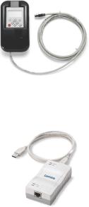
USB diagnostic adapter |
The USB diagnostic adapter is used for the operation, parameterisation, and |
|
diagnostics of the inverter. Data are exchanged between the PC (USB |
|
connection) and the inverter (diagnostic interface on the front) via the |
|
diagnostic adapter. |
|
• Order designation: E94AZCUS |
VFCplus |
Motor control: V/f characteristic control ("Voltage Frequency Control") |
VFCplusEco |
Motor control: V/f characteristic control - energy-saving |
|
In this motor control mode, the inverter adapts the motor voltage to the |
|
requirements of the load. Especially at speeds lower than 50 % of the rated |
|
speed and a reduced torque, losses in the motor and in the inverter can be |
|
reduced. Hence, the usually bad efficiency of the drive in the partial load |
|
operational range is significantly increased. |
|
|
16 |
Lenze · 8400 motec · Reference manual · DMS 10.0 EN · 08/2019 · TD06 |

1 About this documentation
1.4Definition of the notes used
_ _ _ _ _ _ _ _ _ _ _ _ _ _ _ _ _ _ _ _ _ _ _ _ _ _ _ _ _ _ _ _ _ _ _ _ _ _ _ _ _ _ _ _ _ _ _ _ _ _ _ _ _ _ _ _ _ _ _ _ _ _ _ _
1.4Definition of the notes used
The following signal words and symbols are used in this Software Manual to indicate dangers and important information:
Safety instructions
Structure of the safety instructions:
Pictograph and signal word!
(characterise the type and severity of danger)
Note
(describes the danger and gives information about how to prevent dangerous situations)
Pictograph |
Signal word |
Meaning |
|
Danger! |
Danger of personal injury through dangerous electrical voltage |
|
Reference to an imminent danger that may result in death or serious personal injury |
|
|
|
if the corresponding measures are not taken. |
|
|
|
|
Danger! |
Danger of personal injury through a general source of danger |
|
Reference to an imminent danger that may result in death or serious personal injury |
|
|
|
if the corresponding measures are not taken. |
|
|
|
|
Stop! |
Danger of damage to material assets |
|
Reference to a possible danger that may result in property damage if the |
|
|
|
corresponding measures are not taken. |
Application notes |
|
|
|
|
|
Pictograph |
Signal word |
Meaning |
|
Note! |
Important note to ensure trouble-free operation |
|
|
|
|
Tip! |
Useful tip for easy handling |
|
|
|
Lenze · 8400 motec · Reference manual · DMS 10.0 EN · 08/2019 · TD06 |
17 |
1 About this documentation
1.4Definition of the notes used
_ _ _ _ _ _ _ _ _ _ _ _ _ _ _ _ _ _ _ _ _ _ _ _ _ _ _ _ _ _ _ _ _ _ _ _ _ _ _ _ _ _ _ _ _ _ _ _ _ _ _ _ _ _ _ _ _ _ _ _ _ _ _ _
This page has been left blank intentionally,
to present the following information more clearly.
18 |
Lenze · 8400 motec · Reference manual · DMS 10.0 EN · 08/2019 · TD06 |

2 Introduction: Parameterising the inverter
_ _ _ _ _ _ _ _ _ _ _ _ _ _ _ _ _ _ _ _ _ _ _ _ _ _ _ _ _ _ _ _ _ _ _ _ _ _ _ _ _ _ _ _ _ _ _ _ _ _ _ _ _ _ _ _ _ _ _ _ _ _ _ _
2 Introduction: Parameterising the inverter
Being a component of a machine which includes a speed-variable drive system, the inverter needs to be adjusted to its drive task and the motor. The inverter is adjusted by changing parameters which are saved in the memory module. The parameters can be accessed by keypad (diagnosis terminal), by »EASY Starter« or by the »Engineer«. Access is also possible by a master control via fieldbus communication. For this purpose, various communication units are available, e.g. AS-i, CANopen, and PROFIBUS.
Danger!
In general, changing a parameter causes an immediate response in the inverter!
•This may lead to an undesirable response at the motor shaft when the inverter has been enabled!
•Setpoint sources, for instance, may switch over all of a sudden (e.g. when configuring the signal source for the main setpoint).
Certain device commands or settings which may cause critical states of drive behaviour constitute exceptions. Such parameter changes are only possible if the inverter is inhibited. Otherwise, a corresponding error message will be issued.
Lenze · 8400 motec · Reference manual · DMS 10.0 EN · 08/2019 · TD06 |
19 |

2 Introduction: Parameterising the inverter
_ _ _ _ _ _ _ _ _ _ _ _ _ _ _ _ _ _ _ _ _ _ _ _ _ _ _ _ _ _ _ _ _ _ _ _ _ _ _ _ _ _ _ _ _ _ _ _ _ _ _ _ _ _ _ _ _ _ _ _ _ _ _ _
L-force Engineer
L-force EASY Starter
|
|
|
|
Keypad |
|
|
|
|
Parameterisation |
|
Fieldbus |
|
|
|
|
|
|
Signal |
... |
|
|
Signal |
|
inputs |
|
Switch-off positioning |
|
|
outputs |
|
|
|
|
|
|
|
Actuating drive speed |
|
|
|
|
|
|
|
Setpoint |
Motion |
|
|
|
M |
generator |
Control |
|
|
|
|
Kernel |
|
|
|
|
|
|
|
|
|
|
|
|
|
|
|
|
|
|
n |
|
|
|
|
Process |
|
t |
|
|
|
|
|
|
|
|
|
controller |
|
|
|
|
|
Device |
Motor |
M |
|
|
|
control |
control |
|
Signal inputs for control and setpoint signals
Signal flow of the integrated technology application (see the following subchapter)Signal outputs for status and actual value signals
[2-1] Adaptation of the drive solution via parameter setting
20 |
Lenze · 8400 motec · Reference manual · DMS 10.0 EN · 08/2019 · TD06 |
2 Introduction: Parameterising the inverter
2.1Integrated technology applications
_ _ _ _ _ _ _ _ _ _ _ _ _ _ _ _ _ _ _ _ _ _ _ _ _ _ _ _ _ _ _ _ _ _ _ _ _ _ _ _ _ _ _ _ _ _ _ _ _ _ _ _ _ _ _ _ _ _ _ _ _ _ _ _
2.1Integrated technology applications
The following technology applications integrated in the inverter 8400 motec provide the main signal flow for the implementation of a general or a special drive solution:
Technology application "Actuating drive speed"
This preset technology application serves to solve speed-controlled drive tasks, e.g. conveyor drives (interconnected), extruders, test benches, vibrators, travelling drives, presses, machining systems, metering units.
Technology application "actuating drive speed (AC Drive profile)"
This technology application available from version 04.01.00 provides a speed and torque control by means of "AC Drive Profile". For this purpose, the Communication Unit EtherNet/IP™ is required.
"Switch-off positioning" technology application
This technology application available from version 05.00.00 is used to solve speedcontrolled drive tasks which require a pre-switch off or stopping at certain positions, e.g. roller conveyors and conveying belts. The pre-switch off is implemented by connecting switch-off sensors.
Detailed information on each technology application can be found in the main chapter entitled "Technology applications". ( 225)
Lenze · 8400 motec · Reference manual · DMS 10.0 EN · 08/2019 · TD06 |
21 |

2 Introduction: Parameterising the inverter
2.2Selection of the appropriate commissioning tool
_ _ _ _ _ _ _ _ _ _ _ _ _ _ _ _ _ _ _ _ _ _ _ _ _ _ _ _ _ _ _ _ _ _ _ _ _ _ _ _ _ _ _ _ _ _ _ _ _ _ _ _ _ _ _ _ _ _ _ _ _ _ _ _
2.2Selection of the appropriate commissioning tool
There are several possibilities for commissioning the 8400 motec inverter:
Commissioning via keypad X400 (or diagnosis terminal X400)
The keypad is an alternative to the PC for the local operation, parameterisation, and diagnostics in a simple manner. The keypad is especially suited for test and demonstration purposes and for the case that only few parameters have to be adapted.
Note:
•Use the diagnosis terminal for the 8400 motec inverter. The diagnosis terminal combines the keypad with a housing and a connecting cable.
•The description how to make the settings with the keypad also applies to the diagnosis terminal.
Commissioning with PC and »EASY Starter«
The »EASY Starter« is a Lenze tool for easy online diagnostics, parameter setting and commissioning of the inverter.
Commissioning with PC and »Engineer«
The »Engineer« is a Lenze engineering software for parameter setting across all devices, configuring and diagnosing individual components (as for instance inverters, industrial PCs, motors, I/O systems) and machine control systems.
Tip!
The Engineering tools »EASY Starter« and »Engineer StateLevel« are provided free of charge in the internet:
http://www.Lenze.com Download Software downloads
For communication between PC and inverter, the USB diagnostic adapter can be used for instance (see the following subchapter).
22 |
Lenze · 8400 motec · Reference manual · DMS 10.0 EN · 08/2019 · TD06 |
2 Introduction: Parameterising the inverter
2.2Selection of the appropriate commissioning tool
_ _ _ _ _ _ _ _ _ _ _ _ _ _ _ _ _ _ _ _ _ _ _ _ _ _ _ _ _ _ _ _ _ _ _ _ _ _ _ _ _ _ _ _ _ _ _ _ _ _ _ _ _ _ _ _ _ _ _ _ _ _ _ _
2.2.1Overview: Accessories for commissioning
Version |
Features |
Product key |
|
Diagnosis terminal X400 |
Keypad X400 in a robust housing, also suitable for |
EZAEBK2001 |
|
|
installation into the control cabinet door. |
|
|
|
• Supports hot plugging |
|
|
|
• Graphic display with plain texts |
|
|
|
• Backlighting |
|
|
|
• Easy user guidance |
|
|
|
• 4 navigation keys, 2 context-sensitive keys |
|
|
|
• Adjustable RUN/STOP function |
|
|
|
• Incl. 2.5 m cable |
|
|
|
• Enclosure IP20; in case of front installation in control |
|
|
|
cabinet IP65 |
|
|
|
• Can be used for L-force Inverter Drives 8400 and Servo |
|
|
|
Drives 9400 |
|
|
USB diagnostic adapter |
For electrical isolation of your PC and the inverter. |
E94AZCUS |
|
|
• Supports hot plugging |
|
|
|
• Diagnostic LED for data transfer display |
|
|
|
• plug and play |
|
|
|
• Input-side voltage supply via USB connection from PC |
|
|
|
• Output-side voltage supply via the diagnostic interface of |
|
|
|
the inverter |
|
|
|
• Connecting cables can be selected in various lengths: |
|
|
|
|
|
|
Connecting cable for |
2.5 m length |
EWL0070 |
|
USB diagnostic adapter |
|
|
|
5 m length |
EWL0071 |
||
|
|||
|
|
|
|
|
10 m length |
EWL0072 |
|
|
|
|
Fast communication via diagnostic interface
From version 06.01.00, the diagnostic interface also supports the fast communication with 57,600 Baud (instead of 4,800 Baud).
•If no read or write access takes place via the diagnostic interface for 3.5 s, it is changed over to normal communication again with 4,800 Baud.
•57,600 Baud are only possible if the 8400 motec comes with the fast diagnostic interface and an »Engineer« from version 2.19 or a keypad from firmware version 4.2 is connected.
•The current baud rate of the diagnostic interface is displayed in C01905.
Lenze · 8400 motec · Reference manual · DMS 10.0 EN · 08/2019 · TD06 |
23 |
2 Introduction: Parameterising the inverter
2.3General notes on parameters
_ _ _ _ _ _ _ _ _ _ _ _ _ _ _ _ _ _ _ _ _ _ _ _ _ _ _ _ _ _ _ _ _ _ _ _ _ _ _ _ _ _ _ _ _ _ _ _ _ _ _ _ _ _ _ _ _ _ _ _ _ _ _ _
2.3General notes on parameters
All parameters for inverter parameterising or monitoring are saved as so-called "codes".
•The codes are numbered and indicated by the prefix "C" before the code, e.g. "C00002".
•Moreover, each code has a name and specific attributes, as for example access type (reading, writing), data type, limit values and default setting ("Lenze setting").
•For the sake of clarity, some codes contain "subcodes" for saving parameters. This Manual uses a slash "/" as a separator between code and subcode, e.g. C00115/1".
•According to their functionality, the parameters are divided into three groups:
•Setting parameters: For specifying setpoints and for setting device / monitoring functions.
•Configuration parameters: For configuring signal connections and terminal assignments.
•Diagnostic/display parameters: For displaying device-internal process factors, current actual values and status messages. These are read-only parameters.
24 |
Lenze · 8400 motec · Reference manual · DMS 10.0 EN · 08/2019 · TD06 |
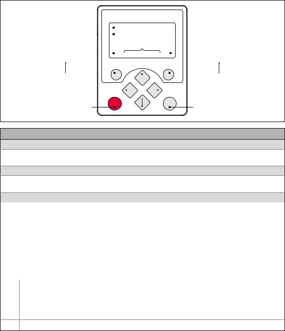
2 Introduction: Parameterising the inverter
2.3General notes on parameters
_ _ _ _ _ _ _ _ _ _ _ _ _ _ _ _ _ _ _ _ _ _ _ _ _ _ _ _ _ _ _ _ _ _ _ _ _ _ _ _ _ _ _ _ _ _ _ _ _ _ _ _ _ _ _ _ _ _ _ _ _ _ _ _
2.3.1Changing the parameterisation with the keypad
Simply connect the diagnosis terminal to the diagnostic interface being located on the top of the device.
•The connecting cable can also be connected to the diagnostic interface during operation and removed again.
Keypad display and control elements
|
Headline |
|
|
|
|
|
|
|
|
|
|
|
|
|
|
|
|
|
LCD display |
|
|
|
|
|
|
|
|
|
|
|
|
|
|
|
|
|
|
|
|||
|
|
|
|
|
|
|
|
|
|
|
|
|
|
|
|
|
|
|
|
|
|
|
|
|
|
|
|
|
|
|
|
|
|
|
|
|
|
|
|
|
|
|
|
|
|
|
|
|
|
|
|
|
|
|
|
|
|
|
|
|
|
|
|
|
|
|
|
|
|
|
|
|
|
|
|
|
|
|
|
|
|
||
Triple-line display |
|
|
|
|
|
|
|
|
|
|
|
|
|
|
|
|
|
|
|
|
|
|
|
|
|
|
|
|
|
|
|
|
|
|
|
|
|
|
|
||
|
|
|
|
|
|
|
|
|
|
|
|
|
|
|
|
|
|
|
||
Device state |
|
|
|
|
|
|
|
|
|
|
|
|
|
|
|
|
|
|
||
|
|
|
|
|
|
|
|
|
|
|
|
|
|
|
|
|
|
|||
Current function |
|
|
|
|
|
|
|
|
|
|
|
|
|
|
|
|
|
Current function |
||
|
|
|
|
|
|
|
|
|
|
|
|
|
|
|
|
|
||||
|
|
|
|
|
|
|
|
|
|
|
|
|
|
|
|
|
||||
left function key |
|
|
|
|
|
|
|
|
|
|
|
|
|
|
|
right function key |
||||
|
|
|
|
|
|
|
|
|
|
|
|
|
|
|
|
|
|
|
|
|
|
|
|
|
|
|
|
|
|
|
|
|
|
|
|
|
|
|
|
|
|
|
|
|
|
|
|
|
|
|
|
|
|
|
|
|
|
|
|
|
|
|
In manual control mode: |
stop |
run |
In manual control mode: |
|
Stop motor |
Start motor |
|||
|
|
LCD display
Headline
In the menu level: Menu name
In the parameter level: Parameter name
Three-part display
In the menu level: List of available menus
In the parameter level: Code/subcode and setting or actual value
Device status
|
Inverter is switched on |
|
Pulse inhibit active |
|
|
|
|
|
Inverter is enabled |
|
System fault active |
|
|
|
|
|
Inverter is inhibited |
|
"Fault" device status is active |
|
|
|
|
|
Quick stop active |
|
"Trouble" device status is active |
|
|
|
|
|
Current limit exceeded |
|
"TroubleQSP" device status is active |
|
|
|
|
|
Speed controller 1 in the limitation |
|
A warning is indicated |
|
|
|
|
Function - left function key |
Function - right function key |
||
Change parameter setting |
|
Accept change in the inverter |
|
|
(change to editing mode) |
|
(no saving with mains failure protection ) |
Back to main menu |
|
Abort (discard change) |
|
|
|
|
|
Parameter can only be changed when the inverter is inhibited |
|||
Save all parameter settings in the memory module safe against mains failure
Lenze · 8400 motec · Reference manual · DMS 10.0 EN · 08/2019 · TD06 |
25 |

2 Introduction: Parameterising the inverter
2.3General notes on parameters
_ _ _ _ _ _ _ _ _ _ _ _ _ _ _ _ _ _ _ _ _ _ _ _ _ _ _ _ _ _ _ _ _ _ _ _ _ _ _ _ _ _ _ _ _ _ _ _ _ _ _ _ _ _ _ _ _ _ _ _ _ _ _ _
Control elements
Execute the function assigned to the function key (see LCD display)
Execute the stop function set in C00469 (Lenze setting: Inhibit inverter)
Deactivate stop function again (Lenze setting: Enable inverter again)
In the menu level: Select menu/submenu |
|
|
In the parameter level: Select parameter |
In the editing mode: Change marked digits or select list entry |
|
In the menu level: Select submenu/change to parameter level In the editing mode: Cursor to the right
In the menu level: One menu level higher (if available) In the parameter level: Back to the menu level
In the editing mode: Cursor to the left
Menu structure
In the keypad, the parameters are classified into various menus and submenus.
•The USER menu includes a selection of frequently used parameters.
•The Code list contains all parameters.
•The Go to param function enables you to reach the corresponding parameter directly.
•The Logbook logs all errors and their chronological history.
•The Diagnostics menu contains diagnostic/display parameters for displaying device-internal process factors, current actual values and status messages.
26 |
Lenze · 8400 motec · Reference manual · DMS 10.0 EN · 08/2019 · TD06 |
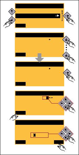
2 Introduction: Parameterising the inverter
2.3General notes on parameters
_ _ _ _ _ _ _ _ _ _ _ _ _ _ _ _ _ _ _ _ _ _ _ _ _ _ _ _ _ _ _ _ _ _ _ _ _ _ _ _ _ _ _ _ _ _ _ _ _ _ _ _ _ _ _ _ _ _ _ _ _ _ _ _
General operation
|
Par1 8400 protec |
|
1. Use the / navigation keys to select the |
1. |
|
desired menu. |
|
|
|
||
|
USER - Menu |
|
• Use the / navigation keys to reach a |
|
Code list |
|
|
|
|
higher/lower menu level. |
|
|
Go To Param |
|
|
|
|
|
|
|
SAVE |
|
• Use the function key to return to the |
|
|
|
main menu. |
|
Load Lenze setting |
2. |
2. Use the / navigation keys to select the |
|
C00002/001 |
|
parameter to be set within a submenu. |
|
|
|
|
|
Off / Finished |
|
3. In order to select another subcode in case of a |
|
EDIT |
|
parameter with subcodes: |
|
|
|
|
|
|
|
• Press the navigation key to change to the |
|
Fixed setpoint 1 |
|
editing mode for the subcode. |
|
C00039/001 |
3. |
• Use the navigation keys to set the desired |
|
40.00 % |
|
subcode. |
|
|
|
|
|
EDIT |
|
4. Use the function key to switch over to the |
|
|
editing mode. |
|
|
|
|
|
|
Fixed setpoint 2 |
|
5. Use the navigation keys to set the desired value. |
|
C00039/002 |
|
6. Use the function key to accept the change |
|
|
|
|
|
60.00 % |
|
and to leave the editing mode. |
|
EDIT |
|
• Use the function key to leave the editing |
4. |
|
mode without accepting the change. |
|
|
|
||
|
Fixed setpoint 2 |
|
|
|
C00039/002 |
5. |
|
|
60.00 % |
|
|
|
ESC |
OK |
|
|
|
6. |
|
[2-2] Example: Changing parameters with the keypad |
|
||
Lenze · 8400 motec · Reference manual · DMS 10.0 EN · 08/2019 · TD06 |
27 |
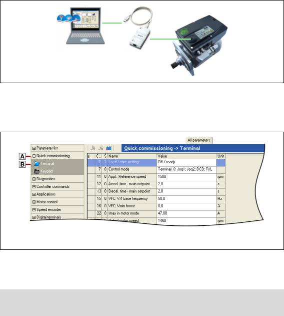
2 Introduction: Parameterising the inverter
2.3General notes on parameters
_ _ _ _ _ _ _ _ _ _ _ _ _ _ _ _ _ _ _ _ _ _ _ _ _ _ _ _ _ _ _ _ _ _ _ _ _ _ _ _ _ _ _ _ _ _ _ _ _ _ _ _ _ _ _ _ _ _ _ _ _ _ _ _
2.3.2Change parameter settings with PC and Lenze software
For communication between the PC (including the L-force »EASY Starter« or L-force »Engineer« software) and the inverter, the USB diagnostic adapter can for instance be used, see the following illustration. The USB diagnostic adapter is the connection between the PC (free USB port) and the inverter (diagnostic interface).
[2-3] Exemplary constellation for parameterising the inverter
The All parameters tab in the »EASY Starter« and the »Engineer« provides a quick access to all parameters of the inverter.
The given categories and subcategories correspond 1:1 to the menus and submenus of the keypad:
Category
Subcategories
[2-4] All parameters tab in the »Engineer«
Moreover, the »Engineer« provides a commissioning interface on the Application parameters tab where you can commission the application in a few steps.
Detailed information on how to handle the »Engineer« can be found in the integrated online help that you can call with the [F1] function key.
28 |
Lenze · 8400 motec · Reference manual · DMS 10.0 EN · 08/2019 · TD06 |

2 Introduction: Parameterising the inverter
2.3General notes on parameters
_ _ _ _ _ _ _ _ _ _ _ _ _ _ _ _ _ _ _ _ _ _ _ _ _ _ _ _ _ _ _ _ _ _ _ _ _ _ _ _ _ _ _ _ _ _ _ _ _ _ _ _ _ _ _ _ _ _ _ _ _ _ _ _
2.3.3User menu for quick access to frequently used parameters
When a system is installed, parameters must be changed time and again until the system runs satisfactorily. The user menu of the inverter contains a selection of frequently used parameters to be able to access and change these parameters quickly:
Parameters |
Name |
Lenze setting |
C00051 |
MCTRL: Actual speed value |
- |
C00053 |
DC-bus voltage |
- |
C00054 |
Motor current |
- |
C00061 |
Heatsink temperature |
- |
C00137 |
Device status |
- |
C00166/3 |
Mess. - status det. error |
- |
C00011 |
Appl.: Reference speed |
1500 rpm |
|
|
|
C00039/1 |
Preset setpoint 1 |
40.0 % |
|
|
|
C00039/2 |
Preset setpoint 2 |
60.0 % |
|
|
|
C00012 |
Acceleration time - main setpoint |
2.0 s |
|
|
|
C00013 |
Deceleration time - main setpoint |
2.0 s |
|
|
|
C00015 |
VFC: V/f base frequency |
50 Hz |
|
|
|
C00016 |
VFC: Vmin boost |
0.0 % |
|
|
|
C00022 |
Imax in motor mode |
depending on the device power |
|
|
|
C00120 |
Setting of motor overload (I2xt) |
100.00 % |
C00087 |
Rated motor speed |
1460 rpm |
|
|
|
C00099 |
Firmware version |
- |
C00200 |
Firmware product type |
- |
C00105 |
Decel. time - quick stop |
5.0 s |
|
|
|
C00173 |
Mains voltage |
0: "3ph 400V" |
|
|
|
Greyed out = display parameter
Tip!
The user menu can be freely configured in C00517.
In the »Engineer«, you can configure the user menu comfortably via the User menu tab (see »Engineer« online help).
Lenze · 8400 motec · Reference manual · DMS 10.0 EN · 08/2019 · TD06 |
29 |

2 Introduction: Parameterising the inverter
2.4Handling the memory module
_ _ _ _ _ _ _ _ _ _ _ _ _ _ _ _ _ _ _ _ _ _ _ _ _ _ _ _ _ _ _ _ _ _ _ _ _ _ _ _ _ _ _ _ _ _ _ _ _ _ _ _ _ _ _ _ _ _ _ _ _ _ _ _
2.4Handling the memory module
Danger!
After power-off, wait at least three minutes before working on the inverter. When removing the memory module, ensure that the inverter is deenergised.
All parameters of the drive system are saved non-volatilely on the memory module. These include the parameters of the inverter and communication-relevant parameters for the communication unit used.
The plug-in version is especially suited for
•restoring an application after replacing a device.
•duplicating identical drive tasks within the frequency inverter series8400 motec, e.g. by using the optionally available EPM Programmer.
Note!
•When the device is switched on, all parameters are automatically loaded from the memory module to the main memory of the inverter.
•When the DIP1 switch on the S1 DIP switch is in the "ON" position, the inverter works with the settings made via DIP switches S1 and S2 and displays them in the corresponding codes.
•The 8400 BaseLine and 8400 motec inverters use the same (grey) memory module. The memory module can be shifted between these inverters, but the inverter must be parameterised newly afterwards.
When handling the memory module, a distinction is drawn between the following scenarios:
Delivery status
•The memory module is plugged into the EPM slot of the drive unit.
•The Lenze setting of the parameters is stored in the memory module.
•The memory module is available as a spare part - without any data.
During operation
•Parameter sets can be saved manually.
•Parameter sets can be loaded manually.
•Parameter changes can be saved automatically.
30 |
Lenze · 8400 motec · Reference manual · DMS 10.0 EN · 08/2019 · TD06 |
Loading...