


 Loading...
EDSPMIO1000
13360344
.E$M
L-force Controls
Software manual
I/O system 1000
L-force I/O System 1000 I Parameter setting & configuration
L

L-force Controls | I/O System 1000
Contents
1 |
About this documentation . . . . . . . . . . . . . . . . . . . . . . . . . . . . . . . . . . . . . . . . . . . . . . . . . . . . . . . . . |
6 |
|
|
1.1 |
Target group . . . . . . . . . . . . . . . . . . . . . . . . . . . . . . . . . . . . . . . . . . . . . . . . . . . . . . . . . . . . . . . . . . . . |
6 |
|
1.2 |
Validity information. . . . . . . . . . . . . . . . . . . . . . . . . . . . . . . . . . . . . . . . . . . . . . . . . . . . . . . . . . . . . |
6 |
|
1.3 |
Document history . . . . . . . . . . . . . . . . . . . . . . . . . . . . . . . . . . . . . . . . . . . . . . . . . . . . . . . . . . . . . . . |
6 |
|
1.4 |
Conventions used . . . . . . . . . . . . . . . . . . . . . . . . . . . . . . . . . . . . . . . . . . . . . . . . . . . . . . . . . . . . . . . |
7 |
|
1.5 |
Terminology used . . . . . . . . . . . . . . . . . . . . . . . . . . . . . . . . . . . . . . . . . . . . . . . . . . . . . . . . . . . . . . . |
8 |
|
1.6 |
Definition of notes used . . . . . . . . . . . . . . . . . . . . . . . . . . . . . . . . . . . . . . . . . . . . . . . . . . . . . . . . . |
9 |
2 |
Product description . . . . . . . . . . . . . . . . . . . . . . . . . . . . . . . . . . . . . . . . . . . . . . . . . . . . . . . . . . . . . . . |
10 |
|
|
2.1 |
Features of the I/O system 1000 . . . . . . . . . . . . . . . . . . . . . . . . . . . . . . . . . . . . . . . . . . . . . . . . . |
10 |
|
2.2 |
Device architecture. . . . . . . . . . . . . . . . . . . . . . . . . . . . . . . . . . . . . . . . . . . . . . . . . . . . . . . . . . . . . . |
11 |
|
2.3 |
Available modules. . . . . . . . . . . . . . . . . . . . . . . . . . . . . . . . . . . . . . . . . . . . . . . . . . . . . . . . . . . . . . . |
12 |
|
2.4 |
Station behaviour after switch-on. . . . . . . . . . . . . . . . . . . . . . . . . . . . . . . . . . . . . . . . . . . . . . . . |
13 |
3 |
Configuring the station structure . . . . . . . . . . . . . . . . . . . . . . . . . . . . . . . . . . . . . . . . . . . . . . . . . . . |
14 |
|
|
3.1 |
Search for connected devices . . . . . . . . . . . . . . . . . . . . . . . . . . . . . . . . . . . . . . . . . . . . . . . . . . . . |
14 |
|
3.2 |
Creating a new project (select component from catalogue) . . . . . . . . . . . . . . . . . . . . . . . . |
18 |
4 |
Communication via system bus (CAN) . . . . . . . . . . . . . . . . . . . . . . . . . . . . . . . . . . . . . . . . . . . . . . . |
23 |
|
|
4.1 |
Establishing a connection between the PC and the device . . . . . . . . . . . . . . . . . . . . . . . . . |
23 |
|
4.2 |
Setting the communication path. . . . . . . . . . . . . . . . . . . . . . . . . . . . . . . . . . . . . . . . . . . . . . . . . |
24 |
|
4.3 |
Establishing an online connection. . . . . . . . . . . . . . . . . . . . . . . . . . . . . . . . . . . . . . . . . . . . . . . . |
26 |
5 |
Navigation . . . . . . . . . . . . . . . . . . . . . . . . . . . . . . . . . . . . . . . . . . . . . . . . . . . . . . . . . . . . . . . . . . . . . . . |
27 |
|
|
5.1 |
Tree topology in the project view. . . . . . . . . . . . . . . . . . . . . . . . . . . . . . . . . . . . . . . . . . . . . . . . . |
27 |
|
5.2 |
Tabs of the modules. . . . . . . . . . . . . . . . . . . . . . . . . . . . . . . . . . . . . . . . . . . . . . . . . . . . . . . . . . . . . |
28 |
6 |
Parameter setting . . . . . . . . . . . . . . . . . . . . . . . . . . . . . . . . . . . . . . . . . . . . . . . . . . . . . . . . . . . . . . . . . |
29 |
|
|
6.1 |
CAN bus coupler . . . . . . . . . . . . . . . . . . . . . . . . . . . . . . . . . . . . . . . . . . . . . . . . . . . . . . . . . . . . . . . . |
30 |
|
6.2 |
Electronic modules - digital input . . . . . . . . . . . . . . . . . . . . . . . . . . . . . . . . . . . . . . . . . . . . . . . . |
31 |
|
|
6.2.1 "DIx, DC24V" and "DIx NPN, DC24V" electronic modules . . . . . . . . . . . . . . . . . . . |
31 |
|
|
6.2.2 "DI2 TimeStamp" electronic module . . . . . . . . . . . . . . . . . . . . . . . . . . . . . . . . . . . . . . |
32 |
|
6.3 |
Electronic modules - digital output . . . . . . . . . . . . . . . . . . . . . . . . . . . . . . . . . . . . . . . . . . . . . . . |
36 |
|
|
6.3.1 "DOx, DC24V" and "DOx NPN, DC24V" electronic modules . . . . . . . . . . . . . . . . . |
36 |
|
|
6.3.2 "DO2 Timestamp" electronic module . . . . . . . . . . . . . . . . . . . . . . . . . . . . . . . . . . . . . |
37 |
|
|
6.3.3 "DO2 PWM" electronic module . . . . . . . . . . . . . . . . . . . . . . . . . . . . . . . . . . . . . . . . . . . |
40 |
|
6.4 |
Electronic module - analog input . . . . . . . . . . . . . . . . . . . . . . . . . . . . . . . . . . . . . . . . . . . . . . . . . |
43 |
|
|
6.4.1 "AIx 12Bit" and "AIx 16Bit" electronic modules . . . . . . . . . . . . . . . . . . . . . . . . . . . . |
43 |
2.0 EN - 11/2010
L 3

L-force Controls | I/O System 1000
|
6.5 |
Electronic modules - analog output . . . . . . . . . . . . . . . . . . . . . . . . . . . . . . . . . . . . . . . . . . . . . . |
44 |
|
|
|
6.5.1 |
"AOx 12Bit" electronic modules. . . . . . . . . . . . . . . . . . . . . . . . . . . . . . . . . . . . . . . . . . . |
44 |
|
6.6 |
Electronic modules - counters. . . . . . . . . . . . . . . . . . . . . . . . . . . . . . . . . . . . . . . . . . . . . . . . . . . . |
46 |
|
|
|
6.6.1 |
Parameters tab . . . . . . . . . . . . . . . . . . . . . . . . . . . . . . . . . . . . . . . . . . . . . . . . . . . . . . . . . . |
46 |
|
|
6.6.2 |
Control of the counter . . . . . . . . . . . . . . . . . . . . . . . . . . . . . . . . . . . . . . . . . . . . . . . . . . . |
49 |
|
|
6.6.3 |
Continuous counting . . . . . . . . . . . . . . . . . . . . . . . . . . . . . . . . . . . . . . . . . . . . . . . . . . . . |
50 |
|
|
6.6.4 |
Counting only once: No main counting direction . . . . . . . . . . . . . . . . . . . . . . . . . . |
51 |
|
|
6.6.5 |
Counting only once: Main counting direction - counting up . . . . . . . . . . . . . . . . |
52 |
|
|
6.6.6 |
Counting only once: Main counting direction - counting down . . . . . . . . . . . . . |
53 |
|
|
6.6.7 |
Periodic counting: No main counting direction . . . . . . . . . . . . . . . . . . . . . . . . . . . . |
54 |
|
|
6.6.8 |
Periodic counting: Main counting direction - counting up . . . . . . . . . . . . . . . . . . |
55 |
|
|
6.6.9 |
Periodic counting: Main counting direction - counting down . . . . . . . . . . . . . . . |
56 |
|
|
6.6.10 |
Function of the hysteresis . . . . . . . . . . . . . . . . . . . . . . . . . . . . . . . . . . . . . . . . . . . . . . . . |
57 |
|
6.7 |
SSI electronic module. . . . . . . . . . . . . . . . . . . . . . . . . . . . . . . . . . . . . . . . . . . . . . . . . . . . . . . . . . . . |
60 |
|
|
|
6.7.1 |
Parameters tab . . . . . . . . . . . . . . . . . . . . . . . . . . . . . . . . . . . . . . . . . . . . . . . . . . . . . . . . . . |
60 |
|
|
6.7.2 |
Operating mode . . . . . . . . . . . . . . . . . . . . . . . . . . . . . . . . . . . . . . . . . . . . . . . . . . . . . . . . . |
62 |
|
6.8 |
Save parameter settings and station structure . . . . . . . . . . . . . . . . . . . . . . . . . . . . . . . . . . . . |
64 |
|
|
6.9 |
Load Lenze setting . . . . . . . . . . . . . . . . . . . . . . . . . . . . . . . . . . . . . . . . . . . . . . . . . . . . . . . . . . . . . . |
64 |
|
7 |
Networking via CAN system bus . . . . . . . . . . . . . . . . . . . . . . . . . . . . . . . . . . . . . . . . . . . . . . . . . . . . |
65 |
||
|
7.1 |
Port assignment . . . . . . . . . . . . . . . . . . . . . . . . . . . . . . . . . . . . . . . . . . . . . . . . . . . . . . . . . . . . . . . . |
65 |
|
|
|
7.1.1 |
PDO mapping . . . . . . . . . . . . . . . . . . . . . . . . . . . . . . . . . . . . . . . . . . . . . . . . . . . . . . . . . . . |
66 |
|
|
7.1.2 |
PDO mapping for digital modules with TimeStamp function . . . . . . . . . . . . . . . |
68 |
|
|
7.1.3 |
PDO mapping for digital modules with PWM function . . . . . . . . . . . . . . . . . . . . . |
70 |
|
|
7.1.4 |
PDO mapping for counters and encoder evaluation (SSI) . . . . . . . . . . . . . . . . . . . |
72 |
|
7.2 |
Creating a network. . . . . . . . . . . . . . . . . . . . . . . . . . . . . . . . . . . . . . . . . . . . . . . . . . . . . . . . . . . . . . |
77 |
|
|
|
7.2.1 |
Insert CAN network . . . . . . . . . . . . . . . . . . . . . . . . . . . . . . . . . . . . . . . . . . . . . . . . . . . . . . |
77 |
|
|
7.2.2 |
Connecting ports of the applications. . . . . . . . . . . . . . . . . . . . . . . . . . . . . . . . . . . . . . |
80 |
|
7.3 |
Configuring the network . . . . . . . . . . . . . . . . . . . . . . . . . . . . . . . . . . . . . . . . . . . . . . . . . . . . . . . . |
81 |
|
|
|
7.3.1 |
Settings tab . . . . . . . . . . . . . . . . . . . . . . . . . . . . . . . . . . . . . . . . . . . . . . . . . . . . . . . . . . . . . |
81 |
|
|
7.3.2 |
Monitoring tab . . . . . . . . . . . . . . . . . . . . . . . . . . . . . . . . . . . . . . . . . . . . . . . . . . . . . . . . . . |
82 |
|
|
7.3.3 |
Diagnostics tab . . . . . . . . . . . . . . . . . . . . . . . . . . . . . . . . . . . . . . . . . . . . . . . . . . . . . . . . . . |
82 |
|
|
7.3.4 |
Process data objects tab. . . . . . . . . . . . . . . . . . . . . . . . . . . . . . . . . . . . . . . . . . . . . . . . . . |
83 |
|
7.4 |
Network management (NMT). . . . . . . . . . . . . . . . . . . . . . . . . . . . . . . . . . . . . . . . . . . . . . . . . . . . |
87 |
|
|
|
7.4.1 |
Communication phases . . . . . . . . . . . . . . . . . . . . . . . . . . . . . . . . . . . . . . . . . . . . . . . . . . |
87 |
|
|
7.4.2 |
Telegram structure . . . . . . . . . . . . . . . . . . . . . . . . . . . . . . . . . . . . . . . . . . . . . . . . . . . . . . |
88 |
|
|
7.4.3 |
State transitions . . . . . . . . . . . . . . . . . . . . . . . . . . . . . . . . . . . . . . . . . . . . . . . . . . . . . . . . . |
89 |
4 |
L |
2.0 EN - 11/2010

L-force Controls | I/O System 1000
8 |
Error management . . . . . . . . . . . . . . . . . . . . . . . . . . . . . . . . . . . . . . . . . . . . . . . . . . . . . . . . . . . . . . . . |
90 |
|
|
8.1 Monitoring . . . . . . . . . . . . . . . . . . . . . . . . . . . . . . . . . . . . . . . . . . . . . . . . . . . . . . . . . . . . . . . . . . . . . |
90 |
|
|
8.1.1 |
Monitoring time for receive objects (0x2400). . . . . . . . . . . . . . . . . . . . . . . . . . . . . . |
90 |
|
8.1.2 |
Heartbeat protocol . . . . . . . . . . . . . . . . . . . . . . . . . . . . . . . . . . . . . . . . . . . . . . . . . . . . . . |
91 |
9 |
Application examples . . . . . . . . . . . . . . . . . . . . . . . . . . . . . . . . . . . . . . . . . . . . . . . . . . . . . . . . . . . . . |
92 |
|
9.1 Communication between I/O system 1000 and Inverter Drive 8400 via CAN fieldbus |
92 |
10 |
Index . . . . . . . . . . . . . . . . . . . . . . . . . . . . . . . . . . . . . . . . . . . . . . . . . . . . . . . . . . . . . . . . . . . . . . . . . . . . |
96 |
|
Your opinion is important to us. . . . . . . . . . . . . . . . . . . . . . . . . . . . . . . . . . . . . . . . . . . . . . . . . . . . . . . . . |
98 |
2.0 EN - 11/2010
L 5

L-force Controls | I/O System 1000
About this documentation
Target group
1 |
About this documentation |
|
This documentation provides information on the L-force I/O system 1000. |
Read the I/O system 1000 system manual before you start working.
The system manual includes safety instructions which must be observed!
Documentation on the I/O system 1000 can be found in the download area at http://www.Lenze.com
1.1Target group
This documentation is directed at all persons who would like to parameterise, configure and diagnose the L-force I/O system 1000 using the L-force »Engineer« engineering software.
1.2Validity information
The information provided in this documentation is valid for the following standard devices:
Product series |
Type designation |
From software version |
I/O systems |
I/O system 1000 |
2.0 |
|
|
|
1.3Document history
Version |
|
|
Description |
|
2.0 |
|
11/2010 |
TD23 |
Amended by EPM-S207, EPM-S310 and EPM-S620 electronic modules |
|
|
|
|
|
1.1 |
|
04/2010 |
TD23 |
Amended by counter modules, SSI module, network management (NMT) |
|
|
|
|
|
1.0 |
|
09/2009 |
TD23 |
First edition |
|
|
|
|
|
6 |
L |
2.0 EN - 11/2010

L-force Controls | I/O System 1000
About this documentation
Conventions used
1.4Conventions used
This documentation uses the following conventions to distinguish between different types of information:
Type of information |
Identification |
Examples/notes |
|
Numbers |
|
|
|
|
|
|
|
|
Decimal separator |
Point |
The decimal point is generally used. |
|
|
|
For instance: 1234.56 |
|
|
|
|
Text |
|
|
|
|
|
|
|
|
Version information |
Blue text colour |
All data that only apply to or from a certain controller |
|
|
|
software version are identified accordingly in this |
|
|
|
documentation. |
|
|
|
Example: This function extension is available from |
|
|
|
software version V3.0! |
|
|
|
|
|
Program name |
» « |
The Lenze »Engineer« PC software ... |
|
|
|
|
|
Window |
italics |
The Message window ... / The Options dialog box ... |
|
|
|
|
|
Variable identifier |
|
By setting bEnable to TRUE ... |
|
|
|
|
|
Control element |
bold |
The OK button ... / The Copy command ... / The |
|
|
|
Properties tab ... / The Name input field ... |
|
|
|
|
|
Sequence of menu |
|
If several commands must be used in sequence to |
|
commands |
|
carry out a function, then the individual commands |
|
|
|
are separated by an arrow. Select the File Open |
|
|
|
command to ... |
|
Shortcut |
<bold> |
Press <F1> to call the online help. |
|
|
|
|
|
|
|
If a key combination is required for a command, a "+" |
|
|
|
is inserted between the key identifiers: Press |
|
|
|
<Shift>+<ESC> ... |
|
|
|
|
|
Program code |
Courier |
IF var1 < var2 THEN |
|
|
|
|
|
Keyword |
Courier bold |
a = a + 1 |
|
|
|
END IF |
|
|
|
|
|
Hyperlink |
underlined |
Optically highlighted reference to another topic. In |
|
|
|
this online documentation activated by means of a |
|
|
|
mouse-click. |
|
|
|
|
Icons |
|
|
|
|
|
|
|
|
Page reference |
( 7) |
Optically highlighted reference to another page. In |
|
|
|
this online documentation activated by means of a |
|
|
|
mouse-click. |
|
|
|
|
|
Step-by-step instructions |
|
Step-by-step instructions are marked by a |
|
|
pictograph. |
|
|
|
|
|
|
|
|
|
All data that only apply to or from a certain software version of the I/O system are identified accordingly in this documentation.
2.0 EN - 11/2010
L 7

L-force Controls | I/O System 1000
About this documentation
Terminology used
1.5Terminology used
Term |
Meaning |
»Engineer« |
Software provided by Lenze that supports the entire life cycle of a machine - |
|
from planning stage to maintenance. |
|
|
Code |
"Container" for one or more parameters which are used to parameterise or |
|
monitor the controller. |
|
|
Subcode |
If a code contains several parameters, these are stored in so-called subcodes. |
|
In this documentation, the diagonal slash "/" is used as a separator between |
|
code and subcode (e.g. "C00118/3"). |
|
|
Function block editor |
Graphical interconnection tool which is provided on the FB Editor tab for |
|
controllers of the licence level Motion Control HighLevel and TopLevel in the |
|
»Engineer« and which can be used to change the configuration of the |
|
accompanying technology applications or extend them by individual functions. |
|
|
Function block |
A function block (FB) can be compared with an integrated circuit that contains a |
|
certain control logic and provides one or several values when being executed. |
|
• An instance (reproduction, copy) of the function block is always inserted into |
|
the circuit. |
|
• It is also possible to insert several instances of a function block into a circuit. |
|
• Each instance has a unique identifier (instance name) and a processing |
|
number which defines the position where the function block is calculated |
|
during the task cycle. |
|
|
System block |
System blocks provide interfaces to basic functions and to the hardware of the |
|
controller in the function block editor of the »Engineer« (e.g. to the digital |
|
inputs). |
|
• In contrast to function blocks, system blocks cannot be instanced. |
|
|
DIS code |
Parameter which displays the current status or value of an input / output of a |
|
system block. |
|
|
TA |
Abbreviation of "technology application". |
|
Technology applications are applications prepared by Lenze which serve as a |
|
basis for solving typical applications. |
|
Every technology application comes with its own online documentation. |
|
|
8 |
L |
2.0 EN - 11/2010

L-force Controls | I/O System 1000
About this documentation
Definition of notes used
1.6Definition of notes used
This documentation uses the following signal words and symbols to indicate dangers and important information:
Safety instructions
Structure of safety instructions:
Danger!
(characterises the type and severity of danger)
Note
(describes the danger and gives information about how to prevent dangerous situations)
Pictograph |
Signal word |
Meaning |
|
Danger! |
Danger of personal injury through dangerous electrical voltage |
|
Reference to an imminent danger that may result in death or serious personal |
|
|
injury if the corresponding measures are not taken. |
|
|
Danger! |
Danger of personal injury through a general source of danger |
|
Reference to an imminent danger that may result in death or serious personal |
|
|
injury if the corresponding measures are not taken. |
|
|
Stop! |
Danger of damage to material assets |
|
Reference to a possible danger that may result in damage to material assets if |
|
|
the corresponding measures are not taken. |
|
Application notes |
|
|
|
|
|
Pictograph |
Signal word |
Meaning |
|
|
|
Note! Important note to ensure trouble-free operation
Tip! |
Useful tip for simple handling |
|
Reference to another documentation |
|
2.0 EN - 11/2010
L 9

L-force Controls | I/O System 1000
Product description
Features of the I/O system 1000
2 |
Product description |
2.1Features of the I/O system 1000
The I/O system 1000 is suitable for the implementation of complex automation applications, consisting of the following components: CAN bus coupler, electronic modules, and backplane bus. The process data exchange via CAN is executed via the CAN bus coupler. The station-internal communication of process and parameter data and the transfer of diagnostic information is executed via the internal backplane bus.
Modular system
Dimensions of electronic module 100 × 76 × 12.5 mm
Dimensions of head end
Mounting on standard DIN rail (35 mm)
Shield connection to standard metal rail (10 mm)
The two-piece structure (separation of electronics and process integration) enables a quick exchange of modules in the event of service
Wiring level via spring terminal (max. 1.5 mm²)
Operation at DC 24 V (DC 20.4 … DC 28.8 V)
Supply voltage of electronics and process level is separated
Up to 64 modules can be connected to a CAN bus coupler
Individual labelling by insertable labels (item designation)
Electrical wiring diagrams are directly printed on the module
Electrical isolation towards the CAN bus and towards process level
Creation of electrical isolations by power supply modules
Support of the communication profile CANopen according to DS301/DS401
10 Receive PDOs (RPDO) and 10 Transmit PDOs (RPDO) are available
Selection between sync-controlled and event-controlled transmission
10 |
L |
2.0 EN - 11/2010
L-force Controls | I/O System 1000
Product description
Device architecture
2.2Device architecture
|
|
... ... |
64 |
4

CAN bus coupler module
Electronic modules, max. 64
nSystem bus (CAN), connected via a 9-pole Sub-D plug
oInternal backplane bus for the communication between CAN bus coupler module and electronic modules
•Side-by-side mounting of the module feet provides for the electrical connection to the CAN bus coupler module.
pSupply voltage DC 24 V, max. 10 A for consumers at output modules
•Side-by-side mounting of the module feet provides for the electrical connection to the CAN bus coupler module.
qSupply voltage DC 24 V for the electronics
•Side-by-side mounting of the module feet provides for the electrical connection to the CAN bus coupler module.
[2-1] Device architecture of the I/O system 1000
2.0 EN - 11/2010
L |
11 |

L-force Controls | I/O System 1000
Product description
Available modules
2.3Available modules
Type designation |
Short designation |
Description |
Process data |
EPM-S110 |
CANopen |
CAN bus coupler |
- |
|
|
|
|
EPM-S200 |
DI2, DC24V |
2 digital inputs |
2 bits |
|
|
|
|
EPM-S201 |
DI4, DC24V |
4 digital inputs |
4 bits |
|
|
|
|
EPM-S202 |
DI8, DC24V |
8 digital inputs |
8 bits |
|
|
|
|
EPM-S203 |
DI4, DC24V |
4 digital inputs |
4 bits |
|
|
• Three-wire conductor connection |
|
|
|
|
|
EPM-S204 |
DI2 NPN, DC24V |
2 digital inputs, npn |
2 bits |
|
|
|
|
EPM-S205 |
DI4 NPN, DC24V |
4 digital inputs, npn |
4 bits |
|
|
|
|
EPM-S206 |
DI8 NPN, DC24V |
8 digital inputs, npn |
8 bits |
|
|
|
|
EPM-S207 |
DI2 Timestamp |
2 digital inputs, ETS |
8 bytes, writing |
|
|
|
|
EPM-S300 |
DO2, DC24V, 0.5A |
2 digital outputs, 0.5 A |
2 bits |
|
|
|
|
EPM-S301 |
DO4, DC24V, 0.5A |
4 digital outputs, 0.5 A |
4 bits |
|
|
|
|
EPM-S302 |
DO8, DC24V, 0.5A |
8 digital outputs, 0.5 A |
8 bits |
|
|
|
|
EPM-S306 |
DO2, DC24V, 2A |
2 digital outputs, 2 A |
2 bits |
|
|
|
|
EPM-S309 |
DO4, DC24V, 2A |
4 digital outputs, 2 A |
4 bits |
|
|
|
|
EPM-S303 |
DO2 NPN, DC24V, 0.5A |
2 digital outputs, npn |
2 bits |
|
|
|
|
EPM-S304 |
DO4 NPN, DC24V, 0.5A |
4 digital outputs, npn |
4 bits |
|
|
|
|
EPM-S305 |
DO8 NPN, DC24V, 0.5A |
8 digital outputs, npn |
8 bits |
|
|
|
|
EPM-S308 |
DO2, relay |
2 relay outputs |
2 bits |
|
|
|
|
EPM-S310 |
DO2 Timestamp |
2 digital outputs, 0.5 A, ETS |
8 bytes, reading |
|
|
|
2 bytes, writing |
|
|
|
|
EPM-S400 |
AI2 12Bit, DC 0…10V |
2 analog inputs, 0 … 10 V DC |
4 bytes |
|
|
|
|
EPM-S401 |
AI4, 12BIT DC 0...10V |
4 analog inputs, 0 … 10 V DC |
8 byte |
|
|
|
|
EPM-S402 |
AI2, 12Bit, DC 0/4…20mA |
2 analog inputs, 0/4 … 20 mA |
4 bytes |
|
|
|
|
EPM-S403 |
AI4, 12Bit, DC 0/4…20mA |
4 analog inputs, 0/4 … 20 mA |
8 byte |
|
|
|
|
EPM-S500 |
AO2, 12Bit, DC 0…10V |
2 analog outputs, 0 … 10 V DC |
4 bytes |
|
|
|
|
EPM-S501 |
AO4, 12Bit, DC 0…10V |
4 analog outputs, 0 … 10 V DC |
8 byte |
|
|
|
|
EPM-S502 |
AO2, 12Bit, DC 0/4…20mA |
2 analog outputs, 0/4 … 20 mA |
4 bytes |
|
|
|
|
EPM-S503 |
AO4, 12Bit, DC 0/4…20mA |
4 analog outputs, 0/4 … 20 mA |
8 bytes |
|
|
|
|
EPM-S404 |
AI2, 16Bit, Resistor |
4 analog inputs for resistance tests |
4 bytes |
|
|
|
|
EPM-S405 |
AI2, 16Bit, Thermo |
2 analog inputs for thermocouple |
4 bytes |
|
|
measurement |
|
|
|
|
|
EPM-S600 |
Counter 1x32Bit, DC24V |
1 counter, 32 bits, 24 V DC (reading, |
12 bytes, reading |
|
|
setting, comparing) |
10 bytes, writing |
|
|
|
|
EPM-S601 |
Counter 2x32Bit, DC24V |
2 counters, 32 bits, 24 V DC (reading, |
12 bytes, reading |
|
|
setting) |
12 bytes, writing |
|
|
|
|
EPM-S602 |
Counter 1x32Bit, DC5V |
1 counter, 32 bits, 5 V DC (reading, |
8 bytes, reading |
|
|
setting) |
10 bytes, writing |
|
|
|
|
EPM-S603 |
Counter 2x32Bit, DC24V |
2 counters, 32 bits, 24 V DC (reading) |
12 bytes, reading |
|
|
|
4 bytes, writing |
|
|
|
|
EPM-S604 |
SSI |
1 SSI absolute value encoder |
6 bytes, reading |
|
|
|
|
EPM-S620 |
DO2 PWM |
2 digital outputs, 0.5 A, PWM |
12 bytes, reading |
|
|
|
4 bytes, writing |
|
|
|
|
12 |
L |
2.0 EN - 11/2010
L-force Controls | I/O System 1000
Product description
Station behaviour after switch-on
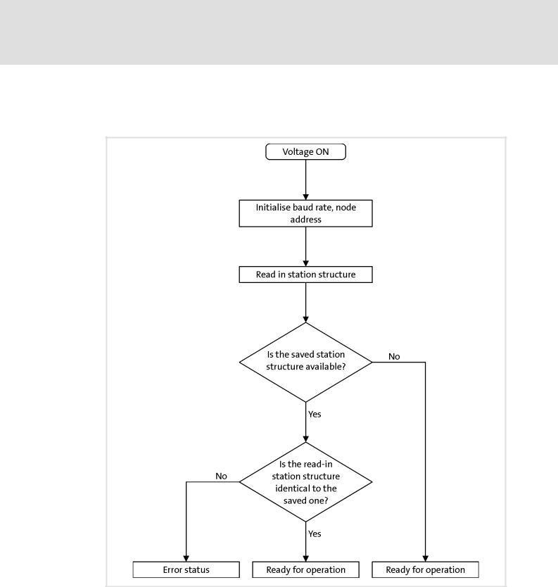
2.4Station behaviour after switch-on
The sequence diagram shows the check routine of the I/O system after every switch-on of the supply voltage.
Save parameter settings and station structure ( 64)
Load Lenze setting ( 64)
2.0 EN - 11/2010
L |
13 |

L-force Controls | I/O System 1000
Configuring the station structure
Search for connected devices
3 |
Configuring the station structure |
3.1Search for connected devices
Instead of starting with an empty project, you can let the »Engineer« search for devices that can be accessed online.
When the search is completed, you can select in the start-up wizard which devices of the ones identified are to be transferred to the project.
Note!
To read out the data, a communication link to the station via system bus (CAN) is required. Communication via system bus (CAN)
Stop!
In the fourth step "Read online data", the start-up wizard establishes automatically an online connection via the selected interface after the Start Search button has been pressed in order to be able to read out data from the connected devices.
14 |
L |
2.0 EN - 11/2010
L-force Controls | I/O System 1000
Configuring the station structure
Search for connected devices
How to create a new project for a connected device:
1.If the start-up wizard has not been displayed yet, click the  icon or select the File New... command to call the start-up wizard.
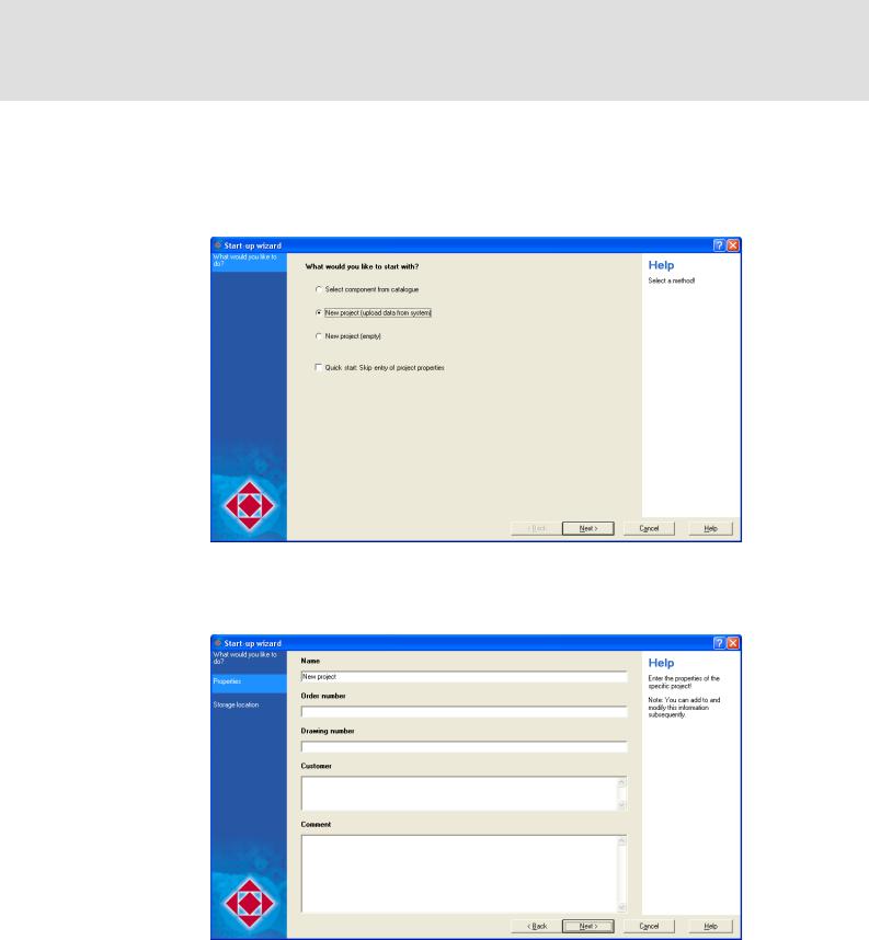
Step 1 - What would you like to do?
2.Select the New project (upload data from system) option.
3.Press Next.
Step 2 - Properties
4.Enter the corresponding properties of the projects into the input fields (name, order number, etc.).
•You can always change the properties subsequently.
•Later you will find the name as project name in the Project view.
5.Press Next.
2.0 EN - 11/2010
L |
15 |
L-force Controls | I/O System 1000
Configuring the station structure
Search for connected devices
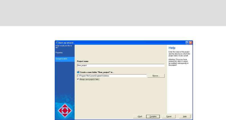
Step 3 - Storage location
6.The Name entered before is suggested as project name. If required, change the suggestion accordingly.
•The project name is also the name for the project directory to be created.
7.Enter the filing location for the project directory in the Directory input field.
•If the indicated directory is not available, it will be recreated.
•You can optionally select an available directory via the Browse... button.
8.Press Complete.
16 |
L |
2.0 EN - 11/2010
L-force Controls | I/O System 1000
Configuring the station structure
Search for connected devices
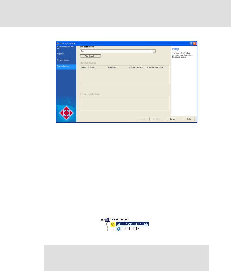
Step 4 - Read online data
9.Select the interface to be used from the Bus connection list field.
10.Click the Start Search button to start the search for connected devices.
•The Find online devices dialog box appears with status messages regarding the search.
•The start-up wizard establishes automatically an online connection via the selected interface to be able to read out data from the connected devices.
11.After the search has been completed, press Close to close the Find online devices dialog box again.
12.Select the devices that are to be transferred to the project to be recreated from the
Identified devices list field.
13.Press Complete.
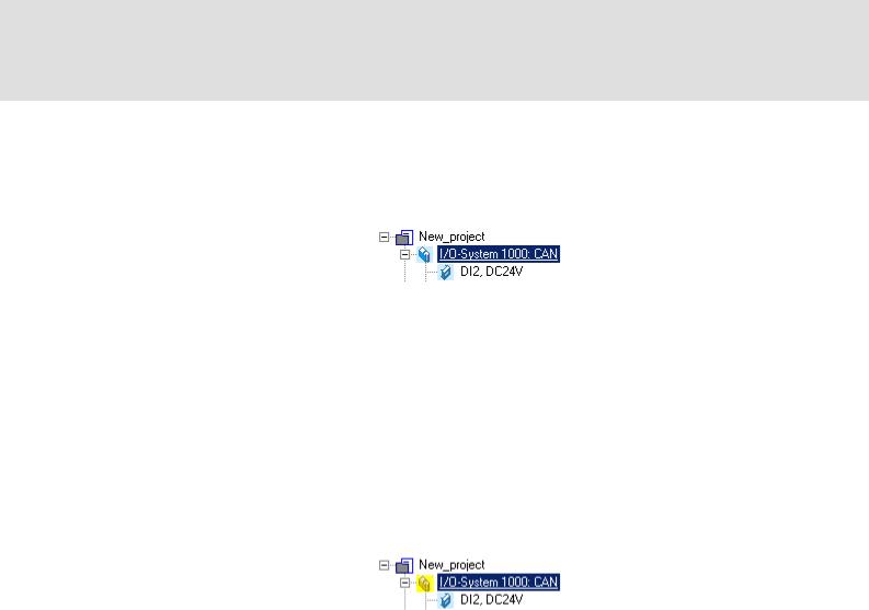
•The project is created with the selected settings. Below the project, all devices selected before are listed in a flat structure.
•Now there already exists an online connection to the selected devices as you can see from the yellow highlighted device icon in the Project view.
Stop!
If you change parameters in the »Engineer« while the device is connected online, the changes will be directly accepted by the device!
2.0 EN - 11/2010
L |
17 |

L-force Controls | I/O System 1000
Configuring the station structure
Creating a new project (select component from catalogue)
3.2Creating a new project (select component from catalogue)
You can create a new project in the »Engineer« without being online. After having configured the project, go online with the I/O system 1000 to transfer parameters.
How to create a new project with components:
1.If the start-up wizard has not been displayed yet, click the  icon or select the File New... command to call the start-up wizard.
Step 1 - What would you like to do?
2.Select the Select component from catalogue option.
3.Press Next.
18 |
L |
2.0 EN - 11/2010

L-force Controls | I/O System 1000
Configuring the station structure
Creating a new project (select component from catalogue)
Step 2 - Properties
4.Enter the corresponding properties of the projects into the input fields (name, order number, etc.).
•You can always change the properties subsequently.
•Later you will find the name as project name in the Project view.
5.Press Next.
Step 3 - Storage location
6.The Name entered before is suggested as project name. If required, change the suggestion accordingly.
•The project name is also the name for the project directory to be created.
2.0 EN - 11/2010
L |
19 |

L-force Controls | I/O System 1000
Configuring the station structure
Creating a new project (select component from catalogue)
7.Enter the filing location for the project directory in the Directory input field.
•If the indicated directory is not available, it will be recreated.
•You can optionally select an available directory via the Browse... button.
•If you select the Always save projects here option, the indicated directory will be the standard memory location for new projects.
8.Press Complete.
•The Insert a component dialog box appears.
Step 4 - Component
9.Select the I/O system tab.
•The Search results list field displays all I/O systems available.
10.Select the "I/O system 1000: CAN" module from the Search results list field.
•More details and technical data of the selected module are displays on the right side.
11.Press Next.
20 |
L |
2.0 EN - 11/2010
L-force Controls | I/O System 1000
Configuring the station structure
Creating a new project (select component from catalogue)
Step 5 - Device modules
12. Use the Select New Module button to insert the first electronic module.
2.0 EN - 11/2010
L |
21 |

L-force Controls | I/O System 1000
Configuring the station structure
Creating a new project (select component from catalogue)
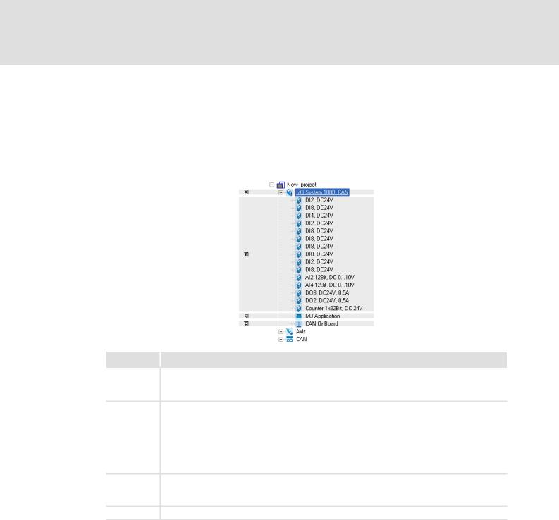
13.Add more electronic modules.
•Use the Select New Module button to put the selected electronic module to the end.
•Use the Insert Module button to insert the selected electronic module in front of the marked module.
•Use the Cut button to remove the marked electronic module.
•Use the Paste button to insert the electronic module cut before in front of the marked module.
•Use the Duplicate button to copy the marked electronic module and insert it in front of it.
•Use the Delete button to delete the marked electronic module.
•Use the ÍÎbuttons to move the marked electronic module to the right or left.
14.Press Complete.
Then, an I/O system 1000 may look as follows:
22 |
L |
2.0 EN - 11/2010

L-force Controls | I/O System 1000
Communication via system bus (CAN)
Establishing a connection between the PC and the device
4 |
Communication via system bus (CAN) |
The PC and the I/O system 1000 communicate via the system bus interface at the CAN bus coupler module. Establishing a connection between the PC and the device
The system bus interface serves to e.g. exchange process data and parameter values between nodes.
The system bus interface transfers CAN objects following the CANopen communication profile CANopen (CiA DS301, version 4.02) developed by the umbrella organisation of CiA (CAN in Automation) in conformity with the CAL (CAN Application Layer).
Tip!
Detailed information is provided in the Lenze library in the "CAN" communication manual.
4.1Establishing a connection between the PC and the device
Lenze offers the following communication accessories for the connection to the PC:
Communication accessories |
PC interface |
PC system bus adapter 2173 |
Parallel interface |
incl. connection cable and voltage supply adapter |
(LPT port) |
•for DIN keyboard connection (EMF2173IB)
•for PS/2 keyboard connection (EMF2173IBV002)
•for PS/2 keyboard connection with electrical isolation (EMF2173IBV003)
PC system bus adapter 2177 |
USB |
incl. connection cable (EMF2177IB) |
(Universal Serial Bus) |
Note!
•Please observe the documentation for the PC system bus adapter!
•For detailed information about the PC system bus adapter, please see the "CAN Communication Manual".
Preconditions:
The 9-pole Sub-D terminal at the CAN bus coupler module must be connected to the LPT port (EMF2173IB) or to a free USB port (EMF2177IB) on the PC via the PC system bus adapter.
The I/O system 1000 is supplied with DC 24 V for the control electronics.
2.0 EN - 11/2010
L |
23 |

L-force Controls | I/O System 1000
Communication via system bus (CAN)
Setting the communication path
4.2Setting the communication path
Note!
The communication settings need to be made only once when the connection to the device is established for the first time. If the Go online command is executed again, the communication path dialog box will not be displayed again, and an online connection will be established immediately via the bus connection set for the device.
To change a communication path that has already been set, go to the Online menu and execute the Set communication path and go online command.
How to configure an online connection via system bus (CAN):
1.Go to the Project view and select the I/O system 1000 to be connected online:
2.Select the Online Set communication path and go online command to open the
Communication path dialog box.
3.In the Communication path dialog box, select the "CAN" entry from the Bus connection list field.
24 |
L |
2.0 EN - 11/2010

L-force Controls | I/O System 1000
Communication via system bus (CAN)
Setting the communication path
4.Click the Search/Enter... button to check the bus connection selected from the Bus connection list field.
•The Select Device Access Path dialog box is displayed:
5.Select the corresponding device in the upper Field devices located list field.
6.Click OK.
•The Select Device Access Path dialog box is closed.
•The Device Access Path column in the Communication path dialog box displays the corresponding device access path (e.g. "can:/dev1/").
7.In the Communication path dialog box, click the Connect button to establish an online connection to the I/O system 1000.
2.0 EN - 11/2010
L |
25 |
L-force Controls | I/O System 1000
Communication via system bus (CAN)
Establishing an online connection
4.3Establishing an online connection
How to establish an online connection via the system bus adapter:
1.Go to the Project view and select the I/O system 1000 to be connected online:
2.Click the  icon.
icon.
If the changes you have made on the project have not been accepted yet, first a query on whether an update is to be carried out is effected.
If an update is to be carried out:
•Click on Yes to open the Update project dialog box.
•Press the Create button in the Update project dialog box to update the changed project elements.
•After the update a note is shown, saying whether the update was carried out successfully.
In the Project view, a yellow icon indicates the online connection to the I/O system 1000:
The  and
and  icons provide an easy possibility to first establish and then disconnect an online connection to the I/O system 1000.
When an online connection has been established, the »Engineer« displays the current parameter settings of the I/O system 1000 with a yellow background colour.
26 |
L |
2.0 EN - 11/2010
L-force Controls | I/O System 1000
Navigation
Tree topology in the project view
5 Navigation
5.1Tree topology in the project view
Similar to the folder view in the Windows Explorer the elements of the current project are shown in a hierarchical tree structure in the Project view of the »Engineer«.
Legend Information
CAN bus coupler module
Port assignment ( 65)
CAN bus coupler ( 30)
Electronic modules
Electronic modules - digital input ( 31)
Electronic modules - digital output ( 36)
Electronic module - analog input ( 43)
Electronic modules - analog output ( 44)
Electronic modules - counters ( 46)
SSI electronic module ( 60)
The Ports and All parameters tabs of the I/O application component are also included in the CAN bus coupler component.
CAN bus coupler ( 30)
Configuring the network ( 81)
2.0 EN - 11/2010
L |
27 |

L-force Controls | I/O System 1000
Navigation
Tabs of the modules
5.2Tabs of the modules
The different tabs in the workspace show the properties and settings of the module currently selected in the Project view and can also be changed here.
Depending on the module selected in the Project view, different tabs are available in the workspace.
When clicking a tab located in the upper position of an index card, you bring the corresponding index card to the fore.
CAN bus coupler module
The Configuration tab shows the composed station.
The Ports tab shows the input and output ports of the CAN bus coupler module.
The All parameters tab lists all objects for parameterising the configured I/O system 1000.
The Properties tab shows project information and catalogue information of the CAN bus coupler module.
The Documentation tab serves to add notes and documents in electronic form to the CAN bus coupler module.
Electronic modules
The Parameters tab lists all parameters of the electronic module.
–Parameterising digital modules:
Polarity of the control signals, error state for digital output modules.
–Parameterising analog modules: Signal functions, error state.
The Properties tab shows project information and catalogue information of the electronic module.
The Documentation tab serves to add notes and documents in electronic form to the electronic module.
28 |
L |
2.0 EN - 11/2010

L-force Controls | I/O System 1000
Parameter setting
6 |
Parameter setting |
The objects of the I/O system 1000 are created dynamically in the Engineer. Depending on the configured electronic modules, only those objects you need for parameter setting are displayed.
•Comfortable parameter setting of electronic modules by selecting the corresponding module from the project view and making the settings in the workspace.
•You can optionally set the parameters via the object lists which are available under the "I/O system 1000: CAN" component, All parameters tab. CAN bus coupler
2.0 EN - 11/2010
L |
29 |
L-force Controls | I/O System 1000
Parameter setting
CAN bus coupler
6.1CAN bus coupler
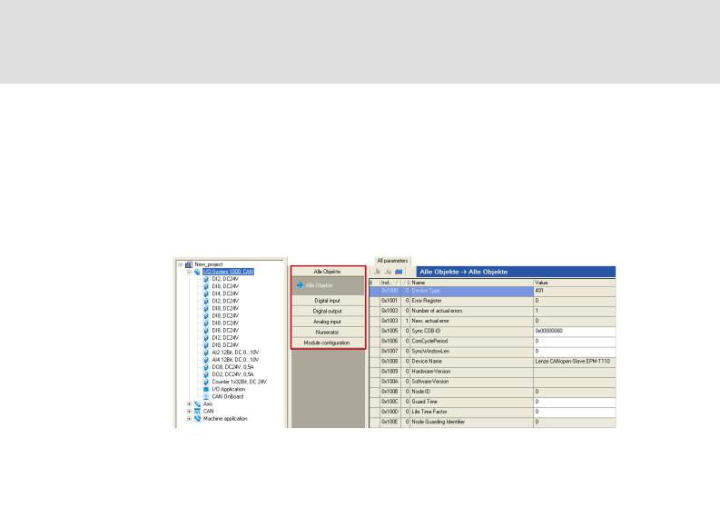
The All parameters tab contains lists of the available objects for setting the parameters of the I/O system 1000.
How to work with the object lists:
1.Select the I/O system 1000 in the project view.
2.Click the All parameters tab in the workspace.
3. Select the desired range of objects.
Legend |
Description |
All objects |
List of all available objects for setting the parameters of the configured I/O |
|
system 1000. |
|
|
Digital input |
List of all available objects for setting the parameters of the "Digital input" |
|
electronic modules. |
|
Electronic modules - digital input |
|
|
Digital output |
List of all available objects for setting the parameters of the "Digital output" |
|
electronic modules. |
|
Electronic modules - digital output |
|
|
Analog input |
List of all available objects for setting the parameters of the "Analog input" |
|
electronic modules. |
|
Electronic module - analog input |
|
|
Analog output |
List of all available objects for setting the parameters of the "Analog output" |
|
electronic modules. |
|
Electronic modules - analog output |
|
|
Numerator |
List of all available objects for setting the parameters of the counter modules |
|
and the SSI module. |
|
Electronic modules - counters |
|
SSI electronic module |
|
|
Module configuration |
List of all available objects for selecting the functions of the "Analog input" |
|
and "Analog output" electronic modules. |
|
Electronic module - analog input |
|
Electronic modules - analog output |
|
|
30 |
L |
2.0 EN - 11/2010
Loading...