


 Loading...
EDS84DMOTPBUS
13395078
Ä.HSoä
L-force Communication
Communication Manual
8400 motec
E84DGFCPxxx
PROFIBUS Communication Unit
L
2 |
L |
EDS84DMOTPBUS EN 3.0 - 11/2011

Communication manual 8400 motec PROFIBUS
Contents
Contents
1 |
About this documentation . . . . . . . . . . . . . . . . . . . . . . . . . . . . . . . . . . . . . . . . . . . . . . . . . . . . . . . . . |
6 |
|
|
1.1 |
Document history . . . . . . . . . . . . . . . . . . . . . . . . . . . . . . . . . . . . . . . . . . . . . . . . . . . . . . . . . . . . . . . |
8 |
|
1.2 |
Conventions used . . . . . . . . . . . . . . . . . . . . . . . . . . . . . . . . . . . . . . . . . . . . . . . . . . . . . . . . . . . . . . . |
9 |
|
1.3 |
Terminology used . . . . . . . . . . . . . . . . . . . . . . . . . . . . . . . . . . . . . . . . . . . . . . . . . . . . . . . . . . . . . . . |
10 |
|
1.4 |
Notes used. . . . . . . . . . . . . . . . . . . . . . . . . . . . . . . . . . . . . . . . . . . . . . . . . . . . . . . . . . . . . . . . . . . . . . |
11 |
2 |
Safety instructions . . . . . . . . . . . . . . . . . . . . . . . . . . . . . . . . . . . . . . . . . . . . . . . . . . . . . . . . . . . . . . . . |
12 |
|
|
2.1 |
General safety and application instructions. . . . . . . . . . . . . . . . . . . . . . . . . . . . . . . . . . . . . . . |
12 |
|
2.2 |
Deviceand application-specific safety instructions . . . . . . . . . . . . . . . . . . . . . . . . . . . . . . . |
13 |
|
2.3 |
Residual hazards . . . . . . . . . . . . . . . . . . . . . . . . . . . . . . . . . . . . . . . . . . . . . . . . . . . . . . . . . . . . . . . . |
13 |
3 |
Product description . . . . . . . . . . . . . . . . . . . . . . . . . . . . . . . . . . . . . . . . . . . . . . . . . . . . . . . . . . . . . . . |
14 |
|
|
3.1 |
Application as directed . . . . . . . . . . . . . . . . . . . . . . . . . . . . . . . . . . . . . . . . . . . . . . . . . . . . . . . . . . |
14 |
|
3.2 |
Features and variants . . . . . . . . . . . . . . . . . . . . . . . . . . . . . . . . . . . . . . . . . . . . . . . . . . . . . . . . . . . |
15 |
|
3.3 |
Connections and interfaces . . . . . . . . . . . . . . . . . . . . . . . . . . . . . . . . . . . . . . . . . . . . . . . . . . . . . . |
16 |
4 |
Technical data . . . . . . . . . . . . . . . . . . . . . . . . . . . . . . . . . . . . . . . . . . . . . . . . . . . . . . . . . . . . . . . . . . . . |
18 |
|
|
4.1 |
General data and operating conditions . . . . . . . . . . . . . . . . . . . . . . . . . . . . . . . . . . . . . . . . . . . |
18 |
|
4.2 |
Protocol data . . . . . . . . . . . . . . . . . . . . . . . . . . . . . . . . . . . . . . . . . . . . . . . . . . . . . . . . . . . . . . . . . . . |
19 |
|
4.3 |
Communication time. . . . . . . . . . . . . . . . . . . . . . . . . . . . . . . . . . . . . . . . . . . . . . . . . . . . . . . . . . . . |
19 |
5 |
Installation . . |
. . . . . . . . . . . . . . . . . . . . . . . . . . . . . . . . . . . . . . . . . . . . . . . . . . . . . . . . . . . . . . . . . . . . . |
20 |
|
|
5.1 |
Mechanical installation. . . . . . . . . . . . . . . . . . . . . . . . . . . . . . . . . . . . . . . . . . . . . . . . . . . . . . . . . . |
21 |
|
|
5.2 |
Electrical installation . . . . . . . . . . . . . . . . . . . . . . . . . . . . . . . . . . . . . . . . . . . . . . . . . . . . . . . . . . . . |
22 |
|
|
|
5.2.1 |
Network topology . . . . . . . . . . . . . . . . . . . . . . . . . . . . . . . . . . . . . . . . . . . . . . . . . . . . . . . |
22 |
|
|
5.2.2 |
Bus termination . . . . . . . . . . . . . . . . . . . . . . . . . . . . . . . . . . . . . . . . . . . . . . . . . . . . . . . . . |
24 |
|
|
5.2.3 |
Bus cable specification . . . . . . . . . . . . . . . . . . . . . . . . . . . . . . . . . . . . . . . . . . . . . . . . . . . |
25 |
|
|
5.2.4 |
PROFIBUS connection . . . . . . . . . . . . . . . . . . . . . . . . . . . . . . . . . . . . . . . . . . . . . . . . . . . . |
26 |
|
|
5.2.5 |
External voltage supply . . . . . . . . . . . . . . . . . . . . . . . . . . . . . . . . . . . . . . . . . . . . . . . . . . |
27 |
6 |
Commissioning . . . . . . . . . . . . . . . . . . . . . . . . . . . . . . . . . . . . . . . . . . . . . . . . . . . . . . . . . . . . . . . . . . . |
28 |
|
|
6.1 |
Before initial switch-on. . . . . . . . . . . . . . . . . . . . . . . . . . . . . . . . . . . . . . . . . . . . . . . . . . . . . . . . . . |
28 |
|
6.2 |
Configuring the host (master). . . . . . . . . . . . . . . . . . . . . . . . . . . . . . . . . . . . . . . . . . . . . . . . . . . . |
29 |
|
6.3 |
Possible settings via DIP switch . . . . . . . . . . . . . . . . . . . . . . . . . . . . . . . . . . . . . . . . . . . . . . . . . . |
30 |
|
|
6.3.1 Receiving the station address via the master . . . . . . . . . . . . . . . . . . . . . . . . . . . . . . |
30 |
|
|
6.3.2 Setting the station address. . . . . . . . . . . . . . . . . . . . . . . . . . . . . . . . . . . . . . . . . . . . . . . |
31 |
|
6.4 |
Initial switch-on. . . . . . . . . . . . . . . . . . . . . . . . . . . . . . . . . . . . . . . . . . . . . . . . . . . . . . . . . . . . . . . . . |
33 |
EDS84DMOTPBUS EN 3.0 - 11/2011
L 3

Communication manual 8400 motec PROFIBUS
Contents
7 |
Data transfer |
. . . . . . . . . . . . . . . . . . . . . . . . . . . . . . . . . . . . . . . . . . . . . . . . . . . . . . . . . . . . . . . . . . . . . |
34 |
|
8 |
Process data transfer . . . . . . . . . . . . . . . . . . . . . . . . . . . . . . . . . . . . . . . . . . . . . . . . . . . . . . . . . . . . . . |
35 |
||
|
8.1 |
Access to process data / PDO mapping . . . . . . . . . . . . . . . . . . . . . . . . . . . . . . . . . . . . . . . . . . . |
35 |
|
|
8.2 |
Port interconnection of the process data objects (PDO) . . . . . . . . . . . . . . . . . . . . . . . . . . . . |
36 |
|
|
8.3 |
Digital and analog input information. . . . . . . . . . . . . . . . . . . . . . . . . . . . . . . . . . . . . . . . . . . . . |
40 |
|
9 |
Parameter data transfer . . . . . . . . . . . . . . . . . . . . . . . . . . . . . . . . . . . . . . . . . . . . . . . . . . . . . . . . . . . |
41 |
||
|
9.1 |
Addressing of the parameter data. . . . . . . . . . . . . . . . . . . . . . . . . . . . . . . . . . . . . . . . . . . . . . . . |
41 |
|
|
9.2 |
DRIVECOM parameter data channel (DP-V0) . . . . . . . . . . . . . . . . . . . . . . . . . . . . . . . . . . . . . . |
42 |
|
|
|
9.2.1 |
Telegram structure (overview). . . . . . . . . . . . . . . . . . . . . . . . . . . . . . . . . . . . . . . . . . . . |
42 |
|
|
9.2.2 |
Byte 1: Service . . . . . . . . . . . . . . . . . . . . . . . . . . . . . . . . . . . . . . . . . . . . . . . . . . . . . . . . . . . |
43 |
|
|
9.2.3 |
Byte 2: Subindex. . . . . . . . . . . . . . . . . . . . . . . . . . . . . . . . . . . . . . . . . . . . . . . . . . . . . . . . . |
46 |
|
|
9.2.4 Bytes 3 + 4: Index . . . . . . . . . . . . . . . . . . . . . . . . . . . . . . . . . . . . . . . . . . . . . . . . . . . . . . . . |
46 |
|
|
|
9.2.5 |
Bytes 5 ... 8: Parameter value / error information . . . . . . . . . . . . . . . . . . . . . . . . . . |
47 |
|
|
9.2.6 |
Error codes . . . . . . . . . . . . . . . . . . . . . . . . . . . . . . . . . . . . . . . . . . . . . . . . . . . . . . . . . . . . . . |
48 |
|
|
9.2.7 |
Telegram examples . . . . . . . . . . . . . . . . . . . . . . . . . . . . . . . . . . . . . . . . . . . . . . . . . . . . . . |
49 |
|
9.3 |
PROFIdrive parameter data channel (DP-V1) . . . . . . . . . . . . . . . . . . . . . . . . . . . . . . . . . . . . . . |
51 |
|
|
|
9.3.1 Connection establishment between master and slave . . . . . . . . . . . . . . . . . . . . . |
52 |
|
|
|
9.3.2 |
Acyclic data transfer . . . . . . . . . . . . . . . . . . . . . . . . . . . . . . . . . . . . . . . . . . . . . . . . . . . . . |
53 |
|
|
9.3.3 |
Telegram structure . . . . . . . . . . . . . . . . . . . . . . . . . . . . . . . . . . . . . . . . . . . . . . . . . . . . . . |
54 |
|
|
9.3.4 |
Error codes . . . . . . . . . . . . . . . . . . . . . . . . . . . . . . . . . . . . . . . . . . . . . . . . . . . . . . . . . . . . . . |
63 |
|
|
9.3.5 |
Telegram examples . . . . . . . . . . . . . . . . . . . . . . . . . . . . . . . . . . . . . . . . . . . . . . . . . . . . . . |
65 |
10 |
Monitoring . . |
. . . . . . . . . . . . . . . . . . . . . . . . . . . . . . . . . . . . . . . . . . . . . . . . . . . . . . . . . . . . . . . . . . . . . |
69 |
|
|
10.1 |
Permanent interruption of PROFIBUS communication. . . . . . . . . . . . . . . . . . . . . . . . . . . . . |
69 |
|
|
10.2 |
Short-time interruption of PROFIBUS communication . . . . . . . . . . . . . . . . . . . . . . . . . . . . . |
70 |
|
|
10.3 |
Settings and displays in the »Engineer« . . . . . . . . . . . . . . . . . . . . . . . . . . . . . . . . . . . . . . . . . . |
71 |
|
11 |
Diagnostics. . |
. . . . . . . . . . . . . . . . . . . . . . . . . . . . . . . . . . . . . . . . . . . . . . . . . . . . . . . . . . . . . . . . . . . . . |
72 |
|
|
11.1 |
LED status displays . . . . . . . . . . . . . . . . . . . . . . . . . . . . . . . . . . . . . . . . . . . . . . . . . . . . . . . . . . . . . . |
72 |
|
|
11.2 |
Diagnostics with the »Engineer« . . . . . . . . . . . . . . . . . . . . . . . . . . . . . . . . . . . . . . . . . . . . . . . . . |
73 |
|
|
11.3 |
Querying the current bus status. . . . . . . . . . . . . . . . . . . . . . . . . . . . . . . . . . . . . . . . . . . . . . . . . . |
74 |
|
|
11.4 |
Diagnostic data . . . . . . . . . . . . . . . . . . . . . . . . . . . . . . . . . . . . . . . . . . . . . . . . . . . . . . . . . . . . . . . . . |
75 |
|
12 |
Error messages . . . . . . . . . . . . . . . . . . . . . . . . . . . . . . . . . . . . . . . . . . . . . . . . . . . . . . . . . . . . . . . . . . . |
77 |
||
|
12.1 |
Short overview (A-Z) of the PROFIBUS error messages . . . . . . . . . . . . . . . . . . . . . . . . . . . . . |
77 |
|
|
12.2 |
Possible causes and remedies . . . . . . . . . . . . . . . . . . . . . . . . . . . . . . . . . . . . . . . . . . . . . . . . . . . . |
78 |
|
4 |
L |
EDS84DMOTPBUS EN 3.0 - 11/2011

Communication manual 8400 motec PROFIBUS
Contents
13 |
Parameter reference. . . . . . . . . . . . . . . . . . . . . . . . . . . . . . . . . . . . . . . . . . . . . . . . . . . . . . . . . . . . . . . |
81 |
|
|
13.1 |
Communication-relevant parameters of the operating system. . . . . . . . . . . . . . . . . . . . . |
81 |
|
13.2 |
Parameters relevant for PROFIBUS communication . . . . . . . . . . . . . . . . . . . . . . . . . . . . . . . |
82 |
|
13.3 |
Table of attributes . . . . . . . . . . . . . . . . . . . . . . . . . . . . . . . . . . . . . . . . . . . . . . . . . . . . . . . . . . . . . . |
89 |
|
13.4 |
Implemented PROFIdrive objects (DP-V1) . . . . . . . . . . . . . . . . . . . . . . . . . . . . . . . . . . . . . . . . . |
91 |
14 |
DIP switch positions for setting the station address . . . . . . . . . . . . . . . . . . . . . . . . . . . . . . . . . . . |
93 |
|
15 |
Index |
. . . . . . . . . . . . . . . . . . . . . . . . . . . . . . . . . . . . . . . . . . . . . . . . . . . . . . . . . . . . . . . . . . . . . . . . . . . . |
97 |
EDS84DMOTPBUS EN 3.0 - 11/2011
L 5

Communication manual 8400 motec PROFIBUS
About this documentation
1 |
About this documentation |
Contents
This documentation exclusively contains descriptions of the PROFIBUS bus system for the Inverter Drive 8400 motec.
Note!
This documentation supplements the mounting instructions and the hardware manual "Inverter Drives 8400 motec" supplied with the controller.
The properties and functions of the PROFIBUS for Inverter Drives 8400 motec are described in detail.
Typical applications are explained with the help of examples. This documentation also contains ...
the most important technical data for PROFIBUS communication;
Information on the installation and commissioning of the PROFIBUS network;
Information on the PROFIBUS data transfer;
Information on monitoring functions and troubleshooting and fault elimination.
The theoretical concepts are only explained to the level of detail required to understand the function of the PROFIBUS communication with Inverter Drives 8400 motec.
Depending on the software version of the controller and on the version of the »Engineer« software installed, the screenshots in this documentation may vary from the »Engineer« depiction.
This documentation does not describe the software of other manufacturers. No responsibility is taken for corresponding information given in this documentation. Information on how to use the software can be obtained from the documents of the host (master).
All brand names used in this documentation are trademarks of their respective owners.
Tip!
Detailed information about PROFIBUS can be found on the website of the PROFIBUS user organisation:
www.profibus.com
6 |
L |
EDS84DMOTPBUS EN 3.0 - 11/2011

Communication manual 8400 motec PROFIBUS
About this documentation
Target group
This documentation is intended for all persons who plan, install, commission and maintain the networking and remote servicing of a machine.
Tip!
Information about and software updates for Lenze products can be found in the download area at:
www.Lenze.com
Validity information
The information given in this documentation is valid for the following devices:
Product series |
Type designation |
Device variant |
|
Inverter Drives 8400 motec |
E84DGFCPxNx |
PROFIBUS |
|
Communication unit PROFIBUS |
|
|
|
E84DGFCPxJx |
PROFIBUS + Safety |
||
|
|||
|
|
|
|
Features and variants ( 15) |
|
|
EDS84DMOTPBUS EN 3.0 - 11/2011
L 7

Communication manual 8400 motec PROFIBUS
About this documentation
Document history
1.1Document history
Version |
|
|
Description |
|
1.0 |
09/2010 |
TD17 |
First edition |
|
|
|
|
|
|
2.0 |
01/2011 |
TD17 |
• DIP switch settings ( 31) corrected. |
|
|
|
|
• |
»Engineer« screenshots updated. |
3.0 |
11/2011 |
TD17 |
• |
General revision |
|
|
|
• Digital and analog input information ( 40) supplemented. |
|
|
|
|
• Description of code C13887 (from version 02.00) supplemented. |
|
Your opinion is important to us!
These instructions were created to the best of our knowledge and belief to give you the best possible support for handling our product.
If you have suggestions for improvement, please e-mail us to: feedback-docu@Lenze.de
Thank you for your support. Your Lenze documentation team
8 |
L |
EDS84DMOTPBUS EN 3.0 - 11/2011

Communication manual 8400 motec PROFIBUS
About this documentation
Conventions used
1.2Conventions used
This manual uses the following conventions to distinguish between different types of information:
Type of information |
Writing |
Examples/notes |
|
Numbers |
|
|
|
|
|
|
|
|
Decimal |
Standard notation |
Example: 1234 |
|
|
|
|
|
Hexadecimal |
0x[0 ... 9, A ... F] |
Example: 0x60F4 |
|
|
|
|
|
Binary |
In inverted commas |
Example: ’100’ |
|
• Nibble |
Point |
Example: ’0110.0100’ |
|
|
|
|
|
Decimal separator |
Point |
The decimal point is always used. |
|
|
|
Example: 1234.56 |
|
|
|
|
Text |
|
|
|
|
|
|
|
|
Program name |
» « |
PC software |
|
|
|
Example: Lenze »Engineer« |
|
|
|
|
|
Control element |
Bold |
The OK button... / The Copy command... / The |
|
|
|
Properties tab... / The Name input field... |
|
|
|
|
|
Hyperlink |
Underlined |
Optically highlighted reference to another topic. Can |
|
|
|
be activated with a mouse-click in this |
|
|
|
documentation. |
|
|
|
|
Symbols |
|
|
|
|
|
|
|
|
Page reference |
( 9) |
Optically highlighted reference to another page. Can |
|
|
|
be activated with a mouse-click in this |
|
|
|
documentation. |
|
|
|
|
|
Step-by-step instructions |
|
Step-by-step instructions are indicated by a |
|
|
pictograph. |
|
|
|
|
|
|
|
|
|
EDS84DMOTPBUS EN 3.0 - 11/2011
L 9

Communication manual 8400 motec PROFIBUS
About this documentation
Terminology used
1.3Terminology used
Term |
Meaning |
Controller |
Lenze frequency inverter of the "Inverter Drives 8400 motec" product series |
|
|
Standard device |
|
|
|
Drive unit |
The controller 8400 motec consists of the following modules: "Drive unit", |
Communication unit |
"communication unit" and "wiring unit". |
Wiring unit |
• The drive unit is available in various power classes. |
|
• The communication unit is available in the following versions: |
|
– No fieldbus |
|
– AS-i option |
|
– CANopen option |
|
– PROFIBUS option |
|
– PROFINET option |
|
– EtherCAT option |
|
• The wiring unit provides flexible connection options for an easy integration |
|
into the power supply of the machine. |
|
|
»Engineer« |
Lenze PC software supporting you during the "Engineering" process |
|
(parameterisation, diagnostics, and configuration) throughout the entire life |
|
cycle, i.e. from planning to maintenance of the machine commissioned. |
|
|
Code |
Parameter by means of which you can parameterise or monitor the controller. In |
|
common parlance, this term is also referred to as an "index". |
|
|
Subcode |
If a code contains more than one parameter, these parameters are stored in |
|
"subcodes". |
|
In this documentation a slash "/" is used as a separator between code and |
|
subcode (e.g. "C00118/3"). |
|
In common parlance, this term is also referred to as a "subindex". |
|
|
Lenze setting |
These are settings the device is preconfigured with ex works. |
|
|
Basic setting |
|
|
|
HW |
Hardware |
|
|
SW |
Software |
|
|
10 |
L |
EDS84DMOTPBUS EN 3.0 - 11/2011
Communication manual 8400 motec PROFIBUS
About this documentation
Notes used
1.4Notes used
The following signal words and symbols are used in this documentation to indicate dangers and important information:
Safety instructions
Structure of the safety instructions:
Pictograph and signal word!
(characterise the type and severity of danger)
Note
(describes the danger and informs how to prevent dangerous situations)
Pictograph |
Signal word |
Meaning |
|
Danger! |
Danger of personal injury through dangerous electrical voltage |
|
Reference to an imminent danger that may result in death or serious |
|
|
personal injury if the corresponding measures are not taken. |
|
|
Danger! |
Danger of personal injury through a general source of danger |
|
Reference to an imminent danger that may result in death or serious |
|
|
personal injury if the corresponding measures are not taken. |
|
|
Stop! |
Danger of property damage |
|
Reference to a possible danger that may result in property damage if the |
|
|
corresponding measures are not taken. |
|
Application notes |
|
|
|
|
|
Pictograph |
Signal word |
Meaning |
|
|
|
Note! Important note to ensure trouble-free operation
|
Tip! |
Useful tip for easy handling |
|
|
Reference to other documents |
|
|
EDS84DMOTPBUS EN 3.0 - 11/2011
L |
11 |

Communication manual 8400 motec PROFIBUS
Safety instructions
General safety and application instructions
2Safety instructions
Note!
Always observe the specified safety measures to avoid severe injury to persons and damage to property!
Always keep this documentation to hand in the vicinity of the product during operation.
2.1General safety and application instructions
Danger!
If you disregard the following basic safety measures, this can cause severe injury to persons and damage to material assets.
Lenze drive and automation components ...
–must only be used as directed. Application as directed ( 14)
–must never be commissioned in the event of visible damage.
–must never be technically modified.
–must never be commissioned before they have been completely mounted.
–must never be operated without the covers required.
–can - depending on their degree of protection - have live, movable or rotating parts during and after operation. Surfaces can be hot.
For Lenze drive components ...
–use only the accessories approved.
–use only original spare parts from the manufacturer.
Observe all specifications given in the attached and associated documentation.
–This is the precondition for safe and trouble-free operation and for achieving the product features specified.
Features and variants ( 15)
–The procedural notes and circuit details described in this document are only proposals. It is up to the user to check whether they can be adapted to the particular applications. Lenze does not take any responsibility for the suitability of the procedures and circuit proposals described.
12 |
L |
EDS84DMOTPBUS EN 3.0 - 11/2011

Communication manual 8400 motec PROFIBUS
Safety instructions
Deviceand application-specific safety instructions
Only qualified personnel may work with and on Lenze drive and automation components. According to IEC 60364 and CENELEC HD 384, these are persons ...
–who are familiar with the installation, assembly, commissioning and operation of the product.
–who have the corresponding qualifications for their work.
–who know all regulations for the prevention of accidents, directives and laws applicable on site and are able to apply them.
2.2Deviceand application-specific safety instructions
During operation, the communication unit must be connected to the wiring unit and the drive unit.
With external voltage supply, always use a separate power supply unit, safely separated to EN 61800-5-1 in every control cabinet ("SELV" / "PELV").
Only use cables that correspond to the given specifications.
Bus cable specification ( 25)
Documentation for "Inverter Drives 8400 motec", control system, system/ machine
All other measures prescribed in this documentation must also be implemented. Observe the safety instructions and application notes specified in the documentation.
2.3Residual hazards Device protection
The communication unit contains electronic components that can be damaged or destroyed by electrostatic discharge.
Installation ( 20)
EDS84DMOTPBUS EN 3.0 - 11/2011
L |
13 |

Communication manual 8400 motec PROFIBUS
Product description
Application as directed
3 |
Product description |
3.1Application as directed
The communication unit PROFIBUS ...
is a unit that can only be used in conjunction with the following modules:
Product series |
Type designation |
Inverter Drives 8400 motec |
E84DGDVxxxxxxxx |
Drive unit |
|
|
|
Inverter Drives 8400 motec |
E84DGVNxx |
Wiring unit |
|
|
|
is a device intended for use in industrial power systems.
may only be operated under the operating conditions specified in this documentation.
may only be used in PROFIBUS networks.
can also be used without being connected to the PROFIBUS network.
Any other use shall be deemed inappropriate!
14 |
L |
EDS84DMOTPBUS EN 3.0 - 11/2011

Communication manual 8400 motec PROFIBUS
Product description
Features and variants
3.2Features and variants
The communication unit PROFIBUS is available in the following versions:
Product series |
Type designation |
Features |
|
|
|
|
|
|
|
Enclosure IP 65 |
PROFIBUS M12 |
I/O: Terminal |
|
I/O: M12 |
Safety |
|
|
|
|
|
|
|
|
Inverter Drives 8400 motec |
E84DGFCPANP |
z |
z |
|
z |
|
|
Communication unit PROFIBUS |
|
|
|
|
|
|
|
E84DGFCP9NP |
z |
z |
|
|
z |
|
|
|
|
|
|
||||
|
|
|
|
|
|
|
|
|
E84DGFCPAJP |
z |
z |
|
z |
|
z |
|
|
|
|
|
|
|
|
|
E84DGFCP9JP |
z |
z |
|
|
z |
z |
|
|
|
|
|
|
|
|
The PROFIBUS communication unit is ...
–mounted on the wiring unit (E84DGVNxx);
–supplied internally via the drive unit (E84DGDVxxxxxxxx) or externally via a separate voltage source.
The I/O connections can be brought into the device via M12 connectors or cable glands.
Devices without integrated safety system (safety option) have no analog input and no relay output.
The integrated safety system of the E84DGFCPxJx communication units can be used on machines for the protection of persons.
Support of the parameter data channel DRIVECOM (DP-V0), PROFIDrive (DP-V1) in preparation
Exchange of up to 8 process data words per direction
Bus coupling via remote bus according to the RS485 standard
Automatic detection of the baud rate (9.6 kbps to 12 Mbps)
Setting of the station address is possible via DIP switch or code.
Communication with the Lenze »Engineer« (access to all Lenze parameters) is executed via the diagnostic interface of the drive unit.
Hardware manual "Inverter Drives 8400 motec"
Here you will find detailed information on the integrated safety system (safety option).
Software manual / »Engineer« online help "Inverter Drives 8400 motec"
Here you will find detailed information on how to configure the safety system (safety option).
EDS84DMOTPBUS EN 3.0 - 11/2011
L |
15 |

Communication manual 8400 motec PROFIBUS
Product description
Connections and interfaces
3.3Connections and interfaces
E84DG029 |
[3-1] Communication unit PROFIBUS
Pos. |
Description |
||
DIP |
DIP switch |
||
|
|
Possible settings via DIP switch ( 30) |
|
A1 / LED |
Position of LEDs for PROFIBUS status display |
||
|
|
LED status displays ( 72) |
|
A2 |
PROFIBUS input (M12 male, 5-pin) |
||
|
|
PROFIBUS connection ( 26) |
|
A3 |
PROFIBUS output (M12 female, 5-pin) |
||
|
|
PROFIBUS connection ( 26) |
|
A4 |
Positions for more freely designable inputs and outputs: |
||
|
• |
Digital inputs |
|
B1 ... B4 |
|||
• |
Digital output |
||
|
|||
|
• Analog input (only for E84DGFCPxJx) |
||
|
• Relay output (only for E84DGFCPxJx) |
||
|
• Connection of safety system "Safety Option" (only for E84DGFCPxJx) |
||
|
|
||
X3 / X4 / X61 |
Terminal strips for wiring the connections at A4 and B1 ... B4 |
||
|
|
||
X5 |
Plug connector for connection to the drive unit |
||
|
|
||
X31 |
Plug connector for wiring the PROFIBUS input at A2 |
||
|
|
||
X32 |
Plug connector for wiring the PROFIBUS output at A3 |
||
|
|
||
X55 |
Plug connector for wiring the LEDs at A1 |
||
|
|
|
|
16 |
L |
EDS84DMOTPBUS EN 3.0 - 11/2011

Communication manual 8400 motec PROFIBUS
Product description
Connections and interfaces
On delivery, the PROFIBUS connections and the LEDs for the PROFIBUS status displays are already mounted and wired:
–PROFIBUS input to plug connector X31
–PROFIBUS output to plug connector X32
–LEDs to plug connector X55
It is also possible to connect the PROFIBUS and other inputs and outputs (e.g. digital inputs) via the positions A1 ... A4 and B1 ... B4.
For the connections, 5-pin M12 connectors or - alternatively - cable glands (cable crosssection max. 1.0 mm2, AWG 18) can be used.
The M12 connectors, cable glands and prefabricated system cables can be obtained from diverse manufacturers.
Wire the M12 connectors or cable glands used to the corresponding contacts of the terminal strips/plug connectors X3, X4 and X61.
Hardware manual "Inverter Drives 8400 motec"
Observe the notes and wiring instructions given in the documentation.
EDS84DMOTPBUS EN 3.0 - 11/2011
L |
17 |

Communication manual 8400 motec PROFIBUS
Technical data
General data and operating conditions
4Technical data
Hardware manual "Inverter Drives 8400 motec"
Here you will find the ambient conditions and information on the electromagnetic compatibility (EMC) that also apply to the communication unit.
4.1General data and operating conditions
Area |
Values |
|
Order designation |
• |
E84DGFCPxNx (PROFIBUS) |
|
• E84DGFCPxJx (PROFIBUS + Safety) |
|
|
|
|
Communication profile |
• PROFIBUS DP-V0 (DRIVECOM) |
|
|
• PROFIBUS DP-V1 (PROFIdrive), from SW version 2.0 |
|
|
|
|
Standards / specifications |
• IEC 61158 / EN 50170 |
|
|
• |
IEC 61784 |
|
|
|
Communication medium |
RS485 |
|
|
|
|
Interface for communication |
• PROFIBUS input: M12 pins, 5-pole, B-coded |
|
|
• PROFIBUS output: M12 socket, 5-pole, B-coded |
|
|
|
|
Max. cable length |
1200 m (depending on the selected baud rate, the used cable type and |
|
|
hardware (repeaters)) |
|
|
|
|
Bus termination |
Bus terminating resistors are required at the first and last PROFIBUS node |
|
|
(implemented in the connector of the bus cable) |
|
|
|
|
Network topology |
• |
Line (without repeater) |
|
• |
Tree/line (with repeater) |
|
|
|
Type of station |
PROFIBUS slave |
|
|
|
|
Number of slave stations |
• Max. 31 (without repeater) |
|
|
• Max. 125 (with repeater) |
|
|
|
|
PNO identification number |
0x0A89 |
|
|
|
|
Baud rate for cable type A (EN 50170) |
9.6 kbps ... 12 Mbps (automatic detection) |
|
|
|
|
External voltage supply |
• U = 24 V DC (20 V - 0 % ... 29 V + 0 %) |
|
|
• Imax = 400 mA |
|
Conformities, approvals |
• |
CE |
|
• |
UR / cUR |
|
|
|
18 |
L |
EDS84DMOTPBUS EN 3.0 - 11/2011

Communication manual 8400 motec PROFIBUS
Technical data
Protocol data
4.2 |
Protocol data |
|
|
|
|
|
Area |
Values |
|
Process data words (PCD) |
1 ... 8 words (16 bits/word) |
|
|
|
|
Cyclic parameter data channel (DP- |
4 words |
|
V0) |
|
|
|
|
|
Acyclic parameter data channel (DP- |
Max. 240 bytes |
|
V1) |
|
|
|
|
|
PROFIBUS user data length |
1 ... 8 words process data channel + 4 words parameter data channel |
|
|
|
4.3Communication time
The communication time is the time between the start of a request and the arrival of the corresponding response.
The communication times in a PROFIBUS network depend on ...
the processing time in the controller;
the transmission delay time (baud rate / telegram length);
the nesting depth of the network.
Processing time in the controller
Data |
Processing time |
|
Process data |
Approx. 2 ms |
update cycle |
|
+ 0 ... 1 ms |
processing time in the module |
|
+ 1 ... x ms |
application task runtime of the technology application used |
|
|
(tolerance) |
|
|
|
Parameter data |
Approx. 30 ms + 20 ms tolerance (typical) |
|
|
• For some codes, the processing time may be longer (see software |
|
|
manual/»Engineer« online help "Inverter Drives 8400 motec"). |
|
|
|
|
There are no interdependencies between parameter data and process data.
EDS84DMOTPBUS EN 3.0 - 11/2011
L |
19 |

Communication manual 8400 motec PROFIBUS
Installation
5Installation
Stop!
Electrostatic discharge
Electronic components within the communication unit can be damaged or destroyed by electrostatic discharge.
Possible consequences:
•The communication unit is defective.
•Communication via the fieldbus is not possible or faulty.
•I/O signals are faulty.
•The safety function is faulty.
Protective measures
• Discharge electrostatic charges before touching the communication unit.
20 |
L |
EDS84DMOTPBUS EN 3.0 - 11/2011

Communication manual 8400 motec PROFIBUS
Installation
Mechanical installation
5.1Mechanical installation
"Inverter Drives 8400 motec" mounting instructions
Here you will find detailed information on the installation.
...0.37 3.0 kW |
|
|
...4.0 7.5 kW |
||||||||||
|
|
|
|
|
|
|
|
|
|
|
|
|
|
|
|
|
|
|
|
|
|
|
|
|
|
|
|
|
|
|
|
|
|
|
|
|
|
|
|
|
|
|
|
|
|
|
|
|
|
|
|
|
|
|
|
|
|
|
|
|
|
|
|
|
|
|
|
|
|
|
|
|
|
|
|
|
|
|
|
|
|
|
|
|
|
|
|
|
|
|
|
|
|
|
|
|
|
|
|
|
|
|
|
|
|
|
|
|
|
|
|
|
|
|
|
|
|
|
|
|
|
|
|
|
|
|
|
|
|
|
|
|
|
|
|
|
|
|
|
|
|
|
|
|
|
|
|
|
|
|
|
|
|
|
|
|
|
|
|
|
|
|
|
|
|
|
|
|
|
|
|
|
|
|
|
|
|
|
|
|
|
|
|
|
|
|
|
|
|
|
|
|
|
|
|
|
|
|
|
|
|
|
|
|
|
|
|
|
|
|
|
|
|
|
|
|
|
|
|
|
|
|
|
|
|
|
|
|
|
|
|
|
|
|
|
|
|
E84DG023a
E84DG023b
[5-1] Mechanical installation of the 8400 motec components
Legend for fig. [5-1]
1 |
Drive unit |
|
|
2 |
Communication unit |
|
|
3 |
Wiring unit |
|
|
A |
Cover of the drive unit |
|
|
EDK84DG... |
Mounting instructions of the drive unit, communication unit, wiring unit |
|
|
EDS84DMOTPBUS EN 3.0 - 11/2011
L |
21 |

Communication manual 8400 motec PROFIBUS
Installation
Electrical installation
5.2Electrical installation
Hardware manual "Inverter Drives 8400 motec"
Here you will find detailed information about ...
•the digital and analog inputs/outputs;
•the relay output;
•the integrated safety system (safety option);
•the wiring of the connections.
Observe the notes and wiring instructions given in the documentation.
5.2.1Network topology
The following examples show two simple RS485 networks.
Every segment of the network must be terminated at both ends. The bus terminators of the PROFIBUS are marked with a "Z" in the below examples.
With a RS485 network of only one segment, the PROFIBUS master (M) with the integrated bus terminating resistor starts the bus. The bus must be terminated by means of a bus terminating resistor at the last PROFIBUS station (S).
M
Z
Z
S 
 S
S 


 S
S
1
E94YCPM012a
[5-2] RS485 network with one segment
An RS485 network consisting of several segments contains repeaters (R) for connecting the segments. The repeaters are provided with integrated bus terminating resistors.
M
|
Z |
|
|
|
|
|
|
|
|
Z |
R |
Z |
|
|
Z |
R |
Z |
|||||
|
|
|
|
|
|
|
|
|
|
|
|
|||||||||||
|
|
|
|
|
|
|
|
|
|
|
|
|
|
|
|
|
|
|
||||
|
|
|
|
|
|
|
|
|
|
|
|
|
|
|
|
|
|
|
|
|
|
|
|
|
|
|
|
|
|
Z |
|
|
|
|
|
|
|
|
|
|
|
|
|||
|
|
|
|
|
|
|
|
|
|
|
|
|
|
|
|
|
|
|
|
|
|
|
|
S |
S |
|
S |
|
|
|
|
|
S |
|
S |
|
|
|
|||||||
|
|
|
|
|
|
|
|
|
|
|
|
|
|
|
|
|
|
|
|
|
|
|
|
|
|
|
|
1 |
|
|
|
|
|
|
2 |
|
|
|
3 |
||||||
|
|
|
|
|
|
|
|
|
|
|
|
|
|
|
|
|
|
|
|
|
|
|
|
|
|
|
|
|
|
|
|
|
|
|
|
|
|
|
|
|
|
|
|
|
|
E94YCPM012b
[5-3] RS485 network with a repeater
22 |
L |
EDS84DMOTPBUS EN 3.0 - 11/2011

Communication manual 8400 motec PROFIBUS
Installation
Electrical installation
If no repeater is to be used at the end of the segment, the bus must be terminated by means of a bus terminating resistor at the last station (S). The bus termination is supplied by this station.
An external supply of the communication unit provides for a supply of the bus termination independent of the supply of the controller.
Note!
The bus terminator must always be supplied. Otherwise, the bus can get unstable.
Bus termination ( 24)
External voltage supply ( 27)
Number of stations
|
|
|
|
|
|
|
|
|
|
|
|
|
|
|
|
|
|
|
|
|
|
|
|
M |
|
|
|
|
|
|
|
|
|
|
|
|
|
|
|
|
|
||
|
|
|
|
|
|
|
|
|
|
|
|
|
|
|
|
|
|
|
|
|
|
|
|
|
|
|
|
|
|
|
|
|
R |
|
|
|
|
|
|
R |
|
||
|
|
|
|
|
|
|
|
|
|
|
|
|
|
|
|
|
|||||
|
|
|
|
|
|
|
|
|
|
|
|
|
|
|
|
|
|
|
|
|
|
|
|
|
|
|
|
|
|
|
|
|
|
|
|
|
|
|
|
|
|
|
|
|
|
S |
|
S |
|
|
S |
|
|
|
S |
|
S |
|
|
|
|
|
|
||
|
|
|
|
|
|
|
|
|
|
|
|
|
|
|
|
|
|
|
|
|
|
|
|
|
|
|
|
|
1 |
|
|
|
|
2 |
|
|
|
3 |
|
||||
|
|
|
|
|
|
|
|
|
|
|
|
|
|
|
|
|
|
|
|
|
2133PFB004 |
|
|
|
|
|
|
|
|
|
|
|
|
|
|
|
|
|
|
|
|
|
|
|
|
|
|
|
|
|
|
|
|
|
|
|
|
|
|
|
|
|
|
|
|
[5-4] Number of stations |
|
|
|
|
|
|
|
|
|
|
|
|
|
|
|
|
|
||||
|
|
|
|
|
|
|
|
|
|
|
|
|
|
||||||||
|
Segment |
|
|
Master (M) |
|
Slave (S) |
|
|
|
|
Repeater (R) |
||||||||||
1 |
|
|
|
|
|
1 |
|
|
|
|
|
31 |
|
|
- |
||||||
|
|
|
|
|
|
|
|
|
|
|
|
|
|
|
|
|
|||||
|
|
|
|
|
|
|
2 |
|
|
|
|
|
30 |
|
|
|
|
- |
|||
|
|
|
|
|
|
|
|
|
|
|
|
|
|
|
|
|
|||||
2 |
|
|
|
|
|
- |
|
|
|
|
|
30 |
|
|
|
|
1 |
||||
|
|
|
|
|
|
|
|
|
|
|
|
|
|
|
|
|
|||||
3 |
|
|
|
|
|
- |
|
|
|
|
|
30 |
|
|
|
|
1 |
||||
|
|
|
|
|
|
|
|
|
|
|
|
|
|
|
|
|
|
|
|
|
|
Tip!
Repeaters do not have a station address. When calculating the maximum number of stations, they reduce the number of stations by 1 on each side of the segment.
Repeaters can be used to build up line and tree topologies. The maximum total bus system expansion depends on ...
•the baud rate used;
•the number of repeaters used.
EDS84DMOTPBUS EN 3.0 - 11/2011
L |
23 |

Communication manual 8400 motec PROFIBUS
Installation
Electrical installation
5.2.2Bus termination
The PROFIBUS must be terminated by means of a bus terminating resistor at the first and last physical station.
In the case of the communication unit, the bus terminating resistor can only be installed externally at the M12 connector. This has the advantage that an installed resistor is visible when the device is closed.
Note!
•The PROFIBUS connections (input and output) must be installed in an enclosed manner. Please use either a connection cable, an enclosed bus terminator connector (M12 male, 4-pin, B-coded) or a cap.
•Connection cables or bus terminator connectors are offered by several cable manufacturers (e.g. Lapp or Turck).
•If you want to disconnect individual bus stations, ensure that the bus terminators at the cable ends remain active. Otherwise, the bus may become unstable.
•Please observe that the bus termination is not active any longer if ...
–the bus terminator connector has been disconnected;
–the mains supply of the drive unit and the external 24V supply of the communication unit have been switched off at the same time.
24 |
L |
EDS84DMOTPBUS EN 3.0 - 11/2011

Communication manual 8400 motec PROFIBUS
Installation
Electrical installation
5.2.3Bus cable specification
Note!
Only use cables that correspond to the given specifications of the PROFIBUS user organisation.
Area |
Values |
Cable resistance |
135 ... 165 Ω/km, (f = 3 ... 20 MHz) |
|
|
Capacitance per unit length |
≤ 30 nF/km |
|
|
Loop resistance |
< 110 Ω/km |
|
|
Core diameter |
> 0.64 mm |
|
|
Core cross-section |
> 0.34 mm2 |
Cores |
Twisted in pairs, insulated and shielded |
|
|
Bus cable length
The bus cable length depends on the baud rate used:
Baud rate |
Length |
9.6 ... 93.75 kbps |
1200 m |
|
|
187.5 kbps |
1000 m |
|
|
500 kbps |
400 m |
|
|
1500 kbps |
200 m |
|
|
3000 ... 12000 kbps |
100 m |
|
|
Note!
The baud rate depending of the data volume, cycle time and number of stations should only be selected as high as required for the application.
Tip!
For high baud rates, we recommend taking the use of optical fibres into consideration.
Advantages of optical fibres:
•External electromagnetic interferences have no effect on the transmission path.
•Bus lengths of several kilometres are also possible with higher baud rates. The bus length is ...
–independent of the baud rate;
–dependent on the optical fibre used.
EDS84DMOTPBUS EN 3.0 - 11/2011
L |
25 |
Communication manual 8400 motec PROFIBUS
Installation
Electrical installation
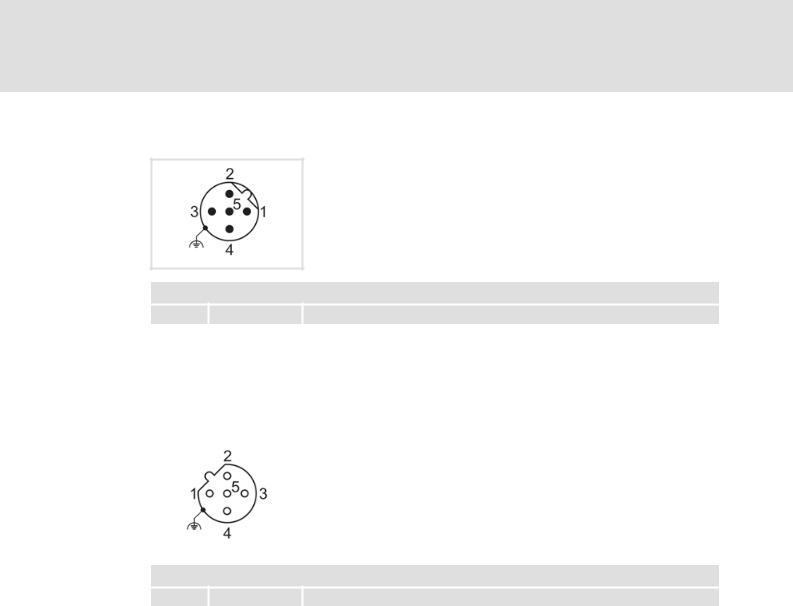
5.2.4PROFIBUS connection
PROFIBUS input: M12 pins, 5-pole, B-coded
Wiring at terminal strip X31
PROFIBUS input
Pin |
Signal |
Description |
1 |
|
Not assigned |
- |
||
|
|
|
2 |
RxD/TxD-N (A) |
Data line A (received/transmitted data, minus) |
|
|
|
3 |
- |
Not assigned |
|
|
|
4 |
RxD/TxD-P (B) |
Data line B (received/transmitted data, plus) |
|
|
|
5 |
- |
Not assigned |
|
|
|
|
|
PROFIBUS output: M12 socket, 5-pole, B-coded |
|
|
|
|
|
Wiring at terminal strip X32 |
|
|
|
PROFIBUS output
Pin |
|
Signal |
|
Description |
1 |
|
P5V2 |
|
5 V DC / 30 mA (bus termination) |
|
|
|||
|
|
|
|
|
2 |
|
RxD/TxD-N (A) |
|
Data line A (received/transmitted data, minus) |
|
|
|
|
|
3 |
|
M5V2 |
|
Data ground (ground to 5 V) |
|
|
|
|
|
4 |
|
RxD/TxD-P (B) |
|
Data line B (received/transmitted data, plus) |
|
|
|
|
|
5 |
|
- |
|
Not assigned (shield connection via housing) |
|
|
|
|
|
26 |
L |
EDS84DMOTPBUS EN 3.0 - 11/2011

Communication manual 8400 motec PROFIBUS
Installation
Electrical installation
5.2.5External voltage supply
By means of the external voltage supply, PROFIBUS communication for commissioning can be established, and the data of the digital and analog inputs can be queried.
Furthermore the external voltage supply serves to maintain PROFIBUS communication if the main supply fails.
The digital inputs RFR, DI1 ... DI5 and the analog input can continue to be evaluated.
The external voltage supply is done via the terminals 24E and GND of the terminal strip X3.
Permissible voltage (DC) / max. current:
–U = 24 V DC (20 V - 0 % ... 29 V + 0 %)
–Imax = 400 mA
Access to parameters of a device that is disconnected from the mains is not possible.
Hardware manual "Inverter Drives 8400 motec"
Here you can find detailed information on how to wire the communication unit.
EDS84DMOTPBUS EN 3.0 - 11/2011
L |
27 |

Communication manual 8400 motec PROFIBUS
Commissioning
Before initial switch-on
6 Commissioning
During commissioning, plant-specific data such as motor parameters, operating parameters, responses, and parameters for fieldbus communication are defined for the controller. Lenze devices use codes for this purpose.
The codes of the controller and for communication are saved to the memory module in a non-volatile data set.
In addition, there are codes for diagnosing and monitoring the stations. Parameter reference ( 81)
6.1Before initial switch-on
Stop!
Before switching on the controller for the first time, check ...
•the entire wiring for completeness, short circuit and earth fault.
•whether the bus system is terminated through a bus terminating resistor at the first and last physical bus station.
Bus termination ( 24)
28 |
L |
EDS84DMOTPBUS EN 3.0 - 11/2011

Communication manual 8400 motec PROFIBUS
Commissioning
Configuring the host (master)
6.2Configuring the host (master)
For communication with the controller, you have to configure the host (master) first.
Configuration for the host (master) and the DP-V0 parameter data channel
For the configuration of the PROFIBUS, the PROFIBUS device description file of the Inverter Drive 8400 motec must be read into the master.
The device description file is available on Lenze's website in the "Services & Downloads" area at:
www.Lenze.com
The following language variants of the device description file can be used:
LENZE84D.GSD (source file, English)
LENZE84D.GSG (German)
LENZE84D.GSE (English)
Defining the user data length
The user data length is defined during the initialisation phase of the master.
The communication unit PROFIBUS supports the configuration of max. 8 process data words (max. 16 bytes).
The user data lengths for process input data and process output data are the same.
EDS84DMOTPBUS EN 3.0 - 11/2011
L |
29 |

Communication manual 8400 motec PROFIBUS
Commissioning
Possible settings via DIP switch
6.3Possible settings via DIP switch
The DIP switches serve to ...
Setting the station address ( 31) (switches: 1 ... 64)
Receiving the station address via the master ( 30) (switch: S)
Lenze setting: all switches in OFF position
[6-1] DIP switch
Note!
•The DIP switches can only be accessed when the drive unit is detached from the communication unit. Loosen the four fixing screws at the drive unit.
Observe the notes in the mounting instructions.
•Switch off the voltage supply of the controller and the external supply of the communication unit before starting with the disassembly of the drive unit.
•The DIP switches are only read in when the device is switched on.
6.3.1Receiving the station address via the master
Set the DIP switch S = OFF, in order to receive the station address automatically via the master.
The station address active at the PROFIBUS is displayed in C13864.
The settings of the DIP switches 1 ... 64 have no effect.
30 |
L |
EDS84DMOTPBUS EN 3.0 - 11/2011
Loading...