


EMF2177IB
Table of contents
 Loading...
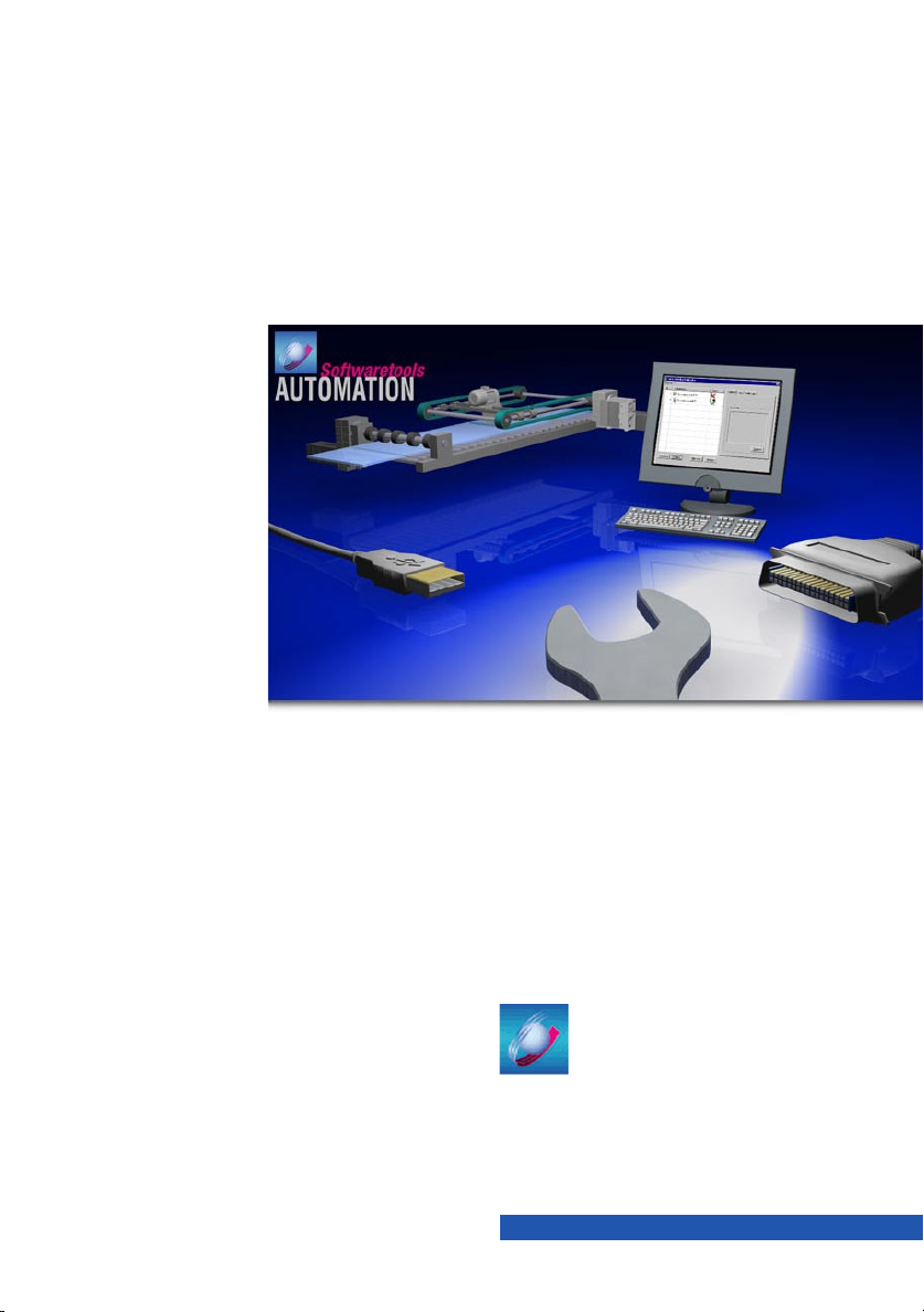
L
Show/Hide Bookmarks
Manual
Global Drive
PC system bus adapter
2173 / 2177
Software installation & configuration

CAUTION:
Show/Hide Bookmarks
The software is supplied to the user as described in this document. Any risks resulting from
its quality or use remain the respons ibility of the user. The user must provide all safety
measures protecting against possible maloperation.
We do not take an y liability for direct or indirect damage, e.g. profit loss, order loss or any
loss regarding business.
Version ID no. Changes
1.1 09/2003 TD11 Revised edition
E 2003 Lenze Drive Systems GmbH
No part of this documentation may be copied or made available to third parties without the explicit
written approval of Lenze Drive Systems GmbH.
All information given in this online documentation has been carefully selected and tested for
compliance with the hardware and software described. Nevertheless, discrepancies cannot be ruled
out. We donot accept any responsibility or liabilityfor any damagethat mayoccur. Required corrections
will be included in the updates of this documentation.
Microsoft, Windows and Windows NT are either registered trademarks or trademarks of Microsoft
Corporation in the USA and/or other countries.
All other product names mentioned in this documentation are trademarks of the corresponding owners.

Contents
Show/Hide Bookmarks
1 Preface and general information 2...................................
1.1 Conventions used 2........................................................
1.2 Terminology used 3........................................................
1.3 Layout of the safety information 3..............................................
2 System requirements 4...........................................
3 Hardware installation 4...........................................
4 Software installation 5............................................
4.1 Driver installation 5........................................................
4.1.1 PC system bus adapter 2173 5........................................
4.1.2 PC system bus adapter 2177 5........................................
4.2 Installation of the system bus configuration tool 6..................................
5 Software configuration 7..........................................
5.1 Activation / deactivation / definition of the system bus adapter as a standard 8.............
5.2 Addition / deletion of system bus adapters 8......................................
5.3 Configuration of the system bus adapter 8........................................
5.3.1 PC system bus adapter 2173 9........................................
5.3.2 PC system bus adapter 2177 11........................................
5.4 Diagnostics 12.............................................................
5.5 Display of driver information 12................................................
5.6 Checking and saving of the configuration 13.......................................
5.7 What’s coming next? 13......................................................
6 Appendix 14.....................................................
6.1 FAQ - Frequently asked questions and answers 14...................................
6.1.1 PC system bus adapter 2173 14........................................
6.1.2 PC system bus adapter 2177 14........................................
6.2 Glossary 15...............................................................
L
1PC system bus adapter EN 1.1
PC system bus adapter 2173 / 2177
Show/Hide Bookmarks
1 Preface and general information
The PC system bus adapter is a communication module for data transfer between a target system
(drive controller, Drive PLC, etc.) and a PC via the system bus (CAN). Two types are available:
• The PC system bus adapter 2173 is the classic type. It is connected to the parallel interface
(LPT port/printer connection) of the PC or notebook.
• The PC system bus adapter 2177 can be used for PCs & notebooks with a USB port (Universal
Serial Bus).
This type is recommended for notebooks which do not have a parallel interface for printer
connection.
Note!
This Manual contains information
• about the software installation of the device drivers required for the PC system bus adapters
and
• the software configuration of the PC system bus adapters using the system bus
configuration tool from Lenze.
Information about the mechanical/electrical connection of the PC system bus adapters can be found
in the corresponding Mounting Instructions for the PC system bus adapters.
1.1 Conventions used
This Manual uses the following conventions to distinguish between different types of information:
Type of information Markin g Example
Names of dialog boxes, input fields
and selection lists
Buttons bold Click Ok to...
Menu commands bold Use the command Copy you can...
Keyboard commands <bold> Use <F1> to open the online help.
2 PC system bus adapter EN 1.1
italics The dialog box Options
If several commands must be used in sequence
to carr y out a function, then the individual commands are separated by an arrow:
WOpen to...
Select File
If a command requires a combination of keys,
the commands are linked with ”+”:
Use <Shift>+<ESC> to...
L
PC system bus adapter 2173 / 2177
Show/Hide Bookmarks
1.2 Terminology used
Ter m In the following text used for
DDS Drive PLC Developer Studio
GDC Global Drive Control
System bus adapter PC system bus adapter 2173 or PC system bus adapter 2177
USB Universal Serial Bus
1.3 Layout of the safety information
• All safety information have a uniform layout:
– The pictograph characterises the type of danger.
– The signal word characterises the severity of danger.
– The note describes the danger and suggests how to avoid the danger.
Signal word
Note
Pictographs used Signal words
Warn ing of
danger to
persons
Warn ing of
damage to
material
Other notes Tip!
Warning of
hazardous
electrical
voltage
Warning of a
general
danger
Danger! Warns of impending danger.
Warning! Warns of potential, very hazardous situations.
Caution! Warns of potential, hazardous situations.
Stop! Warns of potent ial damage to material.
Note!
Consequences if disregarded:
Death or s ever e injuries.
Possible consequences if disregarded:
Death or s ever e injuries.
Possible consequences if disregarded:
Light or minor injuries.
Possible consequences if disregarded:
Damage to the controller/drive system or its
environment.
Indicates a tip or note.
If obser ved, it will make handling the product easier.
L
3PC system bus adapter EN 1.1
PC system bus adapter 2173 / 2177
Show/Hide Bookmarks
2 System requirements
The following minimum requirements on hardware and software must be met in order to use the system
bus adapters:
PC system bu s adapter 2173 PC system bu s adapter 2177
• Microsoft Windows 95/98/Me/NT/2000/XP
• IBM compatible PC
(Pentium 90 processor or higher)
• 32 MB RAM
• Parallel interface (LPT port)
Note:
Please make sure that the operating mode ”ECP”
(Extended Capability Port) is selected for the
parallel interface in the PC BIOS.
The following Lenze tools can be used for communication via the system bus adapters:
• Drive Server
• Global Drive Control (PC system bus adapter 2177: as fro m GDC version 4.3)
• Global Drive Loader
• Global Drive PLC Developer Studio (PC system bus adapter 2177: as from DDS version 1.4)
• Microsoft Windows 98/Me/2000/XP
• IBM compatible PC
(Pentium 266 processor or higher)
• 64 MB (RAM)
(128 MB RA M with Windows 2000/XP)
• Free USB port with 200 mA power supply
Note:
If the PC internal power supply is insufficient for the
USB port a USB hub with external power supply is
required to ensure the power supply of the system
bus adapters!
3 Hardware installation
Information about the mechanical/electrical connection of the system bus adapters can be
found in the corresponding Mounting Instructions for the system bus adapters.
Tip!
System bus adapter LED:
• PC system bus adapter 2173: The LED lights up as soon as the system bus adapter is
connected to the PC and the PC is switched on. If the LED does not light up the system bus
adapter does not work properly.
• PC system bus adapter 2177: The LED only lights up if the operating system has identified
the system bus adapter and found an appropriate driver. The LED flashes as soon as a Lenze
tool communicates via the system bus adapter.
4 PC system bus adapter EN 1.1
L
Loading...