


 Loading...
Engineering tools
Engineer
Configuring drives_ _ _ _ _ _ _ _ _ _ _ _ _ _ _ _ |
Software Manual |
DE |
Ä.PE8ä 13473623
L
Target group
This documentation is intended for all persons who want to use the »Engineer« engineering software to parameterise, configure and diagnose field devices and control systems.
Screenshots/application examples
All screenshots provided in this documentation are application examples. Depending on the firmware version of the Lenze devices and installed engineering tools (here: Lenze »Engineer«), the representation may differ from the actual screen display.
Information regarding the validity
The information in this documentation is valid for the following Lenze software:
Software |
|
|
|
From version |
|
»Engineer« |
|
|
|
2.19 |
|
Document history |
|
|
|
||
|
|
|
|
|
|
Version |
|
|
Description |
||
2.12 |
|
10/2013 |
TD11 |
Updated contents for the »Engineer« V2.19 software version |
|
2.11 |
|
11/2012 |
TD11 |
Updated contents for the »Engineer« V2.17 software version |
|
2.10 |
|
05/2012 |
TD11 |
Updated contents for the »Engineer« V2.16 software version |
|
2.9 |
|
11/2011 |
TD11 |
Updated contents for the »Engineer« V2.15 software version |
|
2.8 |
|
04/2011 |
TD11 |
Updated contents for the »Engineer« V2.14 software version |
|
2.7 |
|
11/2010 |
TD11 |
Updated contents for the »Engineer« V2.13 software version |
|
2.6 |
|
04/2010 |
TD11 |
Updated contents for the »Engineer« V2.12 software version |
|
|
|
|
|
|
|
2.5 |
|
10/2009 |
TD11 |
Updated contents for the software version »Engineer« V2.10 SP3 |
|
2.4 |
|
08/2009 |
TD11 |
Updated chapter: Managing cam data with the »Cam Manager« ( 272) |
|
2.3 |
|
04/2009 |
TD11 |
Optimised structures, update of dialog boxes & extension by new functions |
|
|
|
|
|
of »Engineer« V2.10: |
|
|
|
|
|
• Data logger |
|
|
|
|
|
• Compare and copy parameter sets |
|
2.2 |
|
11/2008 |
TD11 |
Extended by new functions of »Engineer« V2.9: |
|
|
|
|
|
• L-force Loader Export, optimised menu control, device data update and |
|
|
|
|
|
establishing an online connection. |
|
|
|
|
|
• New chapter "Handling catalogues". |
|
2.1 |
|
07/2008 |
TD11 |
Extended by new functions: User motors, Cam Manager, Cam Editor |
|
2.0 |
|
10/2007 |
TD16 |
First edition |
|
|
|
|
|
|
|
Contents
_ _ _ _ _ _ _ _ _ _ _ _ _ _ _ _ _ _ _ _ _ _ _ _ _ _ _ _ _ _ _ _ _ _ _ _ _ _ _ _ _ _ _ _ _ _ _ _ _ _ _ _ _ _ _ _ _ _ _ _ _ _ _ _
1 |
About this documentation _ _ _ _ _ _ _ _ _ _ _ _ _ _ _ _ _ _ _ _ _ _ _ _ _ _ _ _ _ _ _ _ _ _ _ _ _ _ _ |
9 |
||||||
1.1 |
Conventions used |
_ _ _ _ _ _ _ _ _ _ _ _ _ _ _ _ _ _ _ _ _ _ _ _ _ _ _ _ _ _ _ _ _ _ _ _ _ _ _ _ _ _ _ _ |
10 |
|||||
1.2 |
Definition of notes used _ _ _ _ _ _ _ _ _ _ _ _ _ _ _ _ _ _ _ _ _ _ _ _ _ _ _ _ _ _ _ _ _ _ _ _ _ _ _ _ _ |
11 |
||||||
2 |
Safety instructions _ _ _ _ _ _ _ _ _ _ _ _ _ _ _ _ _ _ _ _ _ _ _ _ _ _ _ _ _ _ _ _ _ _ _ _ _ _ _ _ _ _ _ _ |
12 |
||||||
3 |
User interface _ _ _ _ _ _ _ _ _ _ _ _ _ _ _ _ _ _ _ _ _ _ _ _ _ _ _ _ _ _ _ _ _ _ _ _ _ _ _ _ _ _ _ _ _ _ |
13 |
||||||
3.1 |
Toolbar _ _ _ _ _ _ _ _ _ _ _ _ _ _ _ _ _ _ _ _ _ _ _ _ _ _ _ _ _ _ _ _ _ _ _ _ _ _ _ _ _ _ _ _ _ _ _ _ _ _ |
15 |
||||||
3.2 |
Project view bar: Filtering the project tree _ _ _ _ _ _ _ _ _ _ _ _ _ _ _ _ _ _ _ _ _ _ _ _ _ _ _ _ _ _ _ |
17 |
||||||
3.3 |
Project structure (project tree) _ _ _ _ _ _ _ _ _ _ _ _ _ _ _ _ _ _ _ _ _ _ _ _ _ _ _ _ _ _ _ _ _ _ _ _ _ |
18 |
||||||
|
3.3.1 |
History of the preselected elements |
_ _ _ _ _ _ _ _ _ _ _ _ _ _ _ _ _ _ _ _ _ _ _ _ _ _ _ _ _ |
19 |
||||
|
3.3.2 |
General editing functions in the project view _ _ _ _ _ _ _ _ _ _ _ _ _ _ _ _ _ _ _ _ _ _ _ _ |
19 |
|||||
|
3.3.3 |
Shortcuts in the project view _ _ _ _ _ _ _ _ _ _ _ _ _ _ _ _ _ _ _ _ _ _ _ _ _ _ _ _ _ _ _ _ _ |
20 |
|||||
|
3.3.4 |
Project root _ _ _ _ _ _ _ _ _ _ _ _ _ _ _ _ _ _ _ _ _ _ _ _ _ _ _ _ _ _ _ _ _ _ _ _ _ _ _ _ _ _ _ |
21 |
|||||
3.4 |
Workspace _ _ _ _ _ _ _ _ _ _ _ _ _ _ _ _ _ _ _ _ _ _ _ _ _ _ _ _ _ _ _ _ _ _ _ _ _ _ _ _ _ _ _ _ _ _ _ _ |
21 |
||||||
|
3.4.1 |
Displaying parameter values _ _ _ _ _ _ _ _ _ _ _ _ _ _ _ _ _ _ _ _ _ _ _ _ _ _ _ _ _ _ _ _ _ |
22 |
|||||
3.5 |
Status information |
_ _ _ _ _ _ _ _ _ _ _ _ _ _ _ _ _ _ _ _ _ _ _ _ _ _ _ _ _ _ _ _ _ _ _ _ _ _ _ _ _ _ _ |
23 |
|||||
3.6 |
Monitor: Monitoring parameters _ _ _ _ _ _ _ _ _ _ _ _ _ _ _ _ _ _ _ _ _ _ _ _ _ _ _ _ _ _ _ _ _ _ _ _ |
24 |
||||||
|
3.6.1 |
Show monitor window: Accept parameters/type of presentation |
_ _ _ _ _ _ _ _ _ _ _ _ _ |
24 |
||||
|
3.6.2 |
Adapt monitor window: Show parameters graphically (instruments) _ _ _ _ _ _ _ _ _ _ _ |
25 |
|||||
|
3.6.3 |
Adapt monitor window: Present parameters graphically (list) _ _ _ _ _ _ _ _ _ _ _ _ _ _ _ |
26 |
|||||
3.7 |
Create |
_ _ _ _ _ _ _ _ _ _ _ _ _ _ _ _ _ _ _ _ _ _ _ _ _ _ _ _ _ _ _ _ _ _ _ _ _ _ _ _ _ _ _ _ _ _ _ _ _ _ |
27 |
|||||
3.8 |
User menu _ _ _ _ _ _ _ _ _ _ _ _ _ _ _ _ _ _ _ _ _ _ _ _ _ _ _ _ _ _ _ _ _ _ _ _ _ _ _ _ _ _ _ _ _ _ _ _ |
27 |
||||||
3.9 |
Messages _ _ _ _ _ _ _ _ _ _ _ _ _ _ _ _ _ _ _ _ _ _ _ _ _ _ _ _ _ _ _ _ _ _ _ _ _ _ _ _ _ _ _ _ _ _ _ _ _ |
27 |
||||||
3.10 |
Wizards _ _ _ _ _ _ _ _ _ _ _ _ _ _ _ _ _ _ _ _ _ _ _ _ _ _ _ _ _ _ _ _ _ _ _ _ _ _ _ _ _ _ _ _ _ _ _ _ _ _ |
28 |
||||||
3.11 |
Options for the representation/project memory location _ _ _ _ _ _ _ _ _ _ _ _ _ _ _ _ _ _ _ _ _ _ |
29 |
||||||
4 |
Getting started: creating a project _ _ _ _ _ _ _ _ _ _ _ _ _ _ _ _ _ _ _ _ _ _ _ _ _ _ _ _ _ _ _ _ _ _ _ |
30 |
||||||
4.1 |
Creating a new project |
_ _ _ _ _ _ _ _ _ _ _ _ _ _ _ _ _ _ _ _ _ _ _ _ _ _ _ _ _ _ _ _ _ _ _ _ _ _ _ _ _ |
31 |
|||||
|
4.1.1 |
Creating a new project (selecting a component from the catalogue) _ _ _ _ _ _ _ _ _ _ _ _ |
32 |
|||||
|
4.1.2 |
Creating a new project (starting the search for devices connected) |
_ _ _ _ _ _ _ _ _ _ _ _ |
34 |
||||
|
4.1.3 |
Creating an empty project _ _ _ _ _ _ _ _ _ _ _ _ _ _ _ _ _ _ _ _ _ _ _ _ _ _ _ _ _ _ _ _ _ _ _ |
37 |
|||||
4.2 |
Opening the project file _ _ _ _ _ _ _ _ _ _ _ _ _ _ _ _ _ _ _ _ _ _ _ _ _ _ _ _ _ _ _ _ _ _ _ _ _ _ _ _ _ |
38 |
||||||
4.3 |
Updating projects while opening them: Adapting project file from previous version _ _ _ _ _ _ _ _ |
39 |
||||||
4.4 |
Updating catalogues |
_ _ _ _ _ _ _ _ _ _ _ _ _ _ _ _ _ _ _ _ _ _ _ _ _ _ _ _ _ _ _ _ _ _ _ _ _ _ _ _ _ _ |
40 |
|||||
4.5 |
Project properties |
_ _ _ _ _ _ _ _ _ _ _ _ _ _ _ _ _ _ _ _ _ _ _ _ _ _ _ _ _ _ _ _ _ _ _ _ _ _ _ _ _ _ _ _ |
41 |
|||||
4.6 |
Save a project _ _ _ _ _ _ _ _ _ _ _ _ _ _ _ _ _ _ _ _ _ _ _ _ _ _ _ _ _ _ _ _ _ _ _ _ _ _ _ _ _ _ _ _ _ _ |
42 |
||||||
4.7 |
Managing projects in a packed archive _ _ _ _ _ _ _ _ _ _ _ _ _ _ _ _ _ _ _ _ _ _ _ _ _ _ _ _ _ _ _ _ _ |
43 |
||||||
|
4.7.1 |
Saving an archive |
_ _ _ _ _ _ _ _ _ _ _ _ _ _ _ _ _ _ _ _ _ _ _ _ _ _ _ _ _ _ _ _ _ _ _ _ _ _ _ |
43 |
||||
|
4.7.2 |
Open an archive |
_ _ _ _ _ _ _ _ _ _ _ _ _ _ _ _ _ _ _ _ _ _ _ _ _ _ _ _ _ _ _ _ _ _ _ _ _ _ _ _ |
44 |
||||
5 |
Mapping the system structure in the »Engineer« project _ _ _ _ _ _ _ _ _ _ _ _ _ _ _ _ _ _ _ _ _ _ _ |
45 |
||||||
5.1 |
Modularising with system modules and axes |
_ _ _ _ _ _ _ _ _ _ _ _ _ _ _ _ _ _ _ _ _ _ _ _ _ _ _ _ |
47 |
|||||
|
5.1.1 |
Inserting system modules _ _ _ _ _ _ _ _ _ _ _ _ _ _ _ _ _ _ _ _ _ _ _ _ _ _ _ _ _ _ _ _ _ _ _ |
47 |
|||||
|
5.1.2 |
Inserting an axis |
_ _ _ _ _ _ _ _ _ _ _ _ _ _ _ _ _ _ _ _ _ _ _ _ _ _ _ _ _ _ _ _ _ _ _ _ _ _ _ _ |
48 |
||||
5.2 |
Inserting components _ _ _ _ _ _ _ _ _ _ _ _ _ _ _ _ _ _ _ _ _ _ _ _ _ _ _ _ _ _ _ _ _ _ _ _ _ _ _ _ _ _ |
51 |
||||||
|
5.2.1 |
Inserting controllers _ _ _ _ _ _ _ _ _ _ _ _ _ _ _ _ _ _ _ _ _ _ _ _ _ _ _ _ _ _ _ _ _ _ _ _ _ _ |
53 |
|||||
|
5.2.2 |
Inserting application _ _ _ _ _ _ _ _ _ _ _ _ _ _ _ _ _ _ _ _ _ _ _ _ _ _ _ _ _ _ _ _ _ _ _ _ _ _ |
55 |
|||||
|
5.2.3 |
Inserting device modules _ _ _ _ _ _ _ _ _ _ _ _ _ _ _ _ _ _ _ _ _ _ _ _ _ _ _ _ _ _ _ _ _ _ _ |
57 |
|||||
|
5.2.4 |
Inserting controllers _ _ _ _ _ _ _ _ _ _ _ _ _ _ _ _ _ _ _ _ _ _ _ _ _ _ _ _ _ _ _ _ _ _ _ _ _ _ |
58 |
|||||
|
5.2.5 Inserting a motor _ _ _ _ _ _ _ _ _ _ _ _ _ _ _ _ _ _ _ _ _ _ _ _ _ _ _ _ _ _ _ _ _ _ _ _ _ _ _ _ |
58 |
||||||
|
5.2.6 |
Inserting an I/O system _ _ _ _ _ _ _ _ _ _ _ _ _ _ _ _ _ _ _ _ _ _ _ _ _ _ _ _ _ _ _ _ _ _ _ _ |
60 |
|||||
|
|
5.2.6.1 |
System 1000 _ _ _ _ _ _ _ _ _ _ _ _ _ _ _ _ _ _ _ _ _ _ _ _ _ _ _ _ _ _ _ _ _ _ _ _ |
61 |
||||
|
|
5.2.6.2 |
Compact I/O system IP20 _ _ _ _ _ _ _ _ _ _ _ _ _ _ _ _ _ _ _ _ _ _ _ _ _ _ _ _ _ |
61 |
||||
|
|
5.2.6.3 |
Modular I/O system IP20 _ _ _ _ _ _ _ _ _ _ _ _ _ _ _ _ _ _ _ _ _ _ _ _ _ _ _ _ _ |
61 |
||||
3 |
Lenze · Engineer · 2.13 EN - 10/2014 |
Contents
_ _ _ _ _ _ _ _ _ _ _ _ _ _ _ _ _ _ _ _ _ _ _ _ _ _ _ _ _ _ _ _ _ _ _ _ _ _ _ _ _ _ _ _ _ _ _ _ _ _ _ _ _ _ _ _ _ _ _ _ _ _ _ _
|
5.2.7 |
Inserting a power supply module _ _ _ _ _ _ _ _ _ _ _ _ _ _ _ _ _ _ _ _ _ _ _ _ _ _ _ _ _ _ _ |
63 |
|||||
|
5.2.8 |
Inserting the remote maintenance _ _ _ _ _ _ _ _ _ _ _ _ _ _ _ _ _ _ _ _ _ _ _ _ _ _ _ _ _ _ |
66 |
|||||
5.3 |
Inserting a gearbox |
_ _ _ _ _ _ _ _ _ _ _ _ _ _ _ _ _ _ _ _ _ _ _ _ _ _ _ _ _ _ _ _ _ _ _ _ _ _ _ _ _ _ _ |
67 |
|||||
5.4 |
Inserting a device detected online _ _ _ _ _ _ _ _ _ _ _ _ _ _ _ _ _ _ _ _ _ _ _ _ _ _ _ _ _ _ _ _ _ _ _ |
67 |
||||||
5.5 |
Insert from referential project |
_ _ _ _ _ _ _ _ _ _ _ _ _ _ _ _ _ _ _ _ _ _ _ _ _ _ _ _ _ _ _ _ _ _ _ _ _ |
70 |
|||||
5.6 |
Replace component _ _ _ _ _ _ _ _ _ _ _ _ _ _ _ _ _ _ _ _ _ _ _ _ _ _ _ _ _ _ _ _ _ _ _ _ _ _ _ _ _ _ _ |
71 |
||||||
5.7 |
Documentation - Add project details _ _ _ _ _ _ _ _ _ _ _ _ _ _ _ _ _ _ _ _ _ _ _ _ _ _ _ _ _ _ _ _ _ _ |
71 |
||||||
5.8 |
Protecting safe parameters - project-related password entry |
_ _ _ _ _ _ _ _ _ _ _ _ _ _ _ _ _ _ _ _ |
74 |
|||||
6 |
Establishing an online connection _ _ _ _ _ _ _ _ _ _ _ _ _ _ _ _ _ _ _ _ _ _ _ _ _ _ _ _ _ _ _ _ _ _ _ |
75 |
||||||
6.1 |
Build project _ _ _ _ _ _ _ _ _ _ _ _ _ _ _ _ _ _ _ _ _ _ _ _ _ _ _ _ _ _ _ _ _ _ _ _ _ _ _ _ _ _ _ _ _ _ _ |
76 |
||||||
6.2 |
Going online _ _ _ _ _ _ _ _ _ _ _ _ _ _ _ _ _ _ _ _ _ _ _ _ _ _ _ _ _ _ _ _ _ _ _ _ _ _ _ _ _ _ _ _ _ _ _ |
77 |
||||||
|
6.2.1 |
Setting the communication path _ _ _ _ _ _ _ _ _ _ _ _ _ _ _ _ _ _ _ _ _ _ _ _ _ _ _ _ _ _ _ |
79 |
|||||
|
|
6.2.1.1 |
Diagnostic adapter |
_ _ _ _ _ _ _ _ _ _ _ _ _ _ _ _ _ _ _ _ _ _ _ _ _ _ _ _ _ _ _ _ |
80 |
|||
|
|
6.2.1.2 |
CAN _ _ _ _ _ _ _ _ _ _ _ _ _ _ _ _ _ _ _ _ _ _ _ _ _ _ _ _ _ _ _ _ _ _ _ _ _ _ _ _ _ |
81 |
||||
|
|
6.2.1.3 |
Ethernet / Ethernet IPC _ _ _ _ _ _ _ _ _ _ _ _ _ _ _ _ _ _ _ _ _ _ _ _ _ _ _ _ _ _ |
83 |
||||
|
|
6.2.1.4 |
PROFIBUS |
_ _ _ _ _ _ _ _ _ _ _ _ _ _ _ _ _ _ _ _ _ _ _ _ _ _ _ _ _ _ _ _ _ _ _ _ _ |
84 |
|||
|
|
6.2.1.5 |
PROFINET _ _ _ _ _ _ _ _ _ _ _ _ _ _ _ _ _ _ _ _ _ _ _ _ _ _ _ _ _ _ _ _ _ _ _ _ _ _ |
85 |
||||
|
|
6.2.1.6 |
Gateway controller -> CAN _ _ _ _ _ _ _ _ _ _ _ _ _ _ _ _ _ _ _ _ _ _ _ _ _ _ _ _ |
85 |
||||
|
|
6.2.1.7 |
Gateway controller -> EtherCAT _ _ _ _ _ _ _ _ _ _ _ _ _ _ _ _ _ _ _ _ _ _ _ _ _ |
86 |
||||
|
|
6.2.1.8 |
Gateway Controller -> EtherCAT ADS (Beckhoff) _ _ _ _ _ _ _ _ _ _ _ _ _ _ _ _ |
87 |
||||
|
|
6.2.1.9 |
Gateway Siemens - STEP 7 Communication Server (available by call in STEP 7) |
89 |
||||
|
6.2.2 |
Checking the serial number _ _ _ _ _ _ _ _ _ _ _ _ _ _ _ _ _ _ _ _ _ _ _ _ _ _ _ _ _ _ _ _ _ _ |
94 |
|||||
|
|
6.2.2.1 |
Communication path is currently being used by another device _ _ _ _ _ _ _ _ |
94 |
||||
|
|
6.2.2.2 |
Communication path is currently being used by another device _ _ _ _ _ _ _ _ |
95 |
||||
|
|
6.2.2.3 |
Switching off the serial number check _ _ _ _ _ _ _ _ _ _ _ _ _ _ _ _ _ _ _ _ _ _ |
96 |
||||
6.3 |
Going offline _ _ _ _ _ _ _ _ _ _ _ _ _ _ _ _ _ _ _ _ _ _ _ _ _ _ _ _ _ _ _ _ _ _ _ _ _ _ _ _ _ _ _ _ _ _ _ |
96 |
||||||
6.4 |
System bus configurator |
_ _ _ _ _ _ _ _ _ _ _ _ _ _ _ _ _ _ _ _ _ _ _ _ _ _ _ _ _ _ _ _ _ _ _ _ _ _ _ _ |
96 |
|||||
6.5 |
PROFINET address configurator _ _ _ _ _ _ _ _ _ _ _ _ _ _ _ _ _ _ _ _ _ _ _ _ _ _ _ _ _ _ _ _ _ _ _ _ _ |
97 |
||||||
6.6 |
EtherNet / IP addresses configurator _ _ _ _ _ _ _ _ _ _ _ _ _ _ _ _ _ _ _ _ _ _ _ _ _ _ _ _ _ _ _ _ _ _ |
97 |
||||||
7 |
Device functions with active online connection _ _ _ _ _ _ _ _ _ _ _ _ _ _ _ _ _ _ _ _ _ _ _ _ _ _ _ _ |
98 |
||||||
7.1 |
Options _ _ _ _ _ _ _ _ _ _ _ _ _ _ _ _ _ _ _ _ _ _ _ _ _ _ _ _ _ _ _ _ _ _ _ _ _ _ _ _ _ _ _ _ _ _ _ _ _ _ |
99 |
||||||
7.2 |
Controlling an inverter: Enable/inhibit, start stop application _ _ _ _ _ _ _ _ _ _ _ _ _ _ _ _ _ _ _ _ |
100 |
||||||
|
7.2.1 |
Enable controller _ _ _ _ _ _ _ _ _ _ _ _ _ _ _ _ _ _ _ _ _ _ _ _ _ _ _ _ _ _ _ _ _ _ _ _ _ _ _ _ |
100 |
|||||
|
7.2.2 |
Inhibit controller _ _ _ _ _ _ _ _ _ _ _ _ _ _ _ _ _ _ _ _ _ _ _ _ _ _ _ _ _ _ _ _ _ _ _ _ _ _ _ _ |
101 |
|||||
|
7.2.3 |
Start application |
_ _ _ _ _ _ _ _ _ _ _ _ _ _ _ _ _ _ _ _ _ _ _ _ _ _ _ _ _ _ _ _ _ _ _ _ _ _ _ _ |
101 |
||||
|
7.2.4 |
Stop application |
_ _ _ _ _ _ _ _ _ _ _ _ _ _ _ _ _ _ _ _ _ _ _ _ _ _ _ _ _ _ _ _ _ _ _ _ _ _ _ _ |
101 |
||||
7.3 |
Application and parameter set transfer |
_ _ _ _ _ _ _ _ _ _ _ _ _ _ _ _ _ _ _ _ _ _ _ _ _ _ _ _ _ _ _ _ |
102 |
|||||
|
7.3.1 |
Download program to device _ _ _ _ _ _ _ _ _ _ _ _ _ _ _ _ _ _ _ _ _ _ _ _ _ _ _ _ _ _ _ _ _ |
103 |
|||||
|
7.3.2 |
Download parameter set to device _ _ _ _ _ _ _ _ _ _ _ _ _ _ _ _ _ _ _ _ _ _ _ _ _ _ _ _ _ _ |
105 |
|||||
|
7.3.3 |
Upload parameter set _ _ _ _ _ _ _ _ _ _ _ _ _ _ _ _ _ _ _ _ _ _ _ _ _ _ _ _ _ _ _ _ _ _ _ _ _ |
106 |
|||||
|
7.3.4 |
Save parameter set |
_ _ _ _ _ _ _ _ _ _ _ _ _ _ _ _ _ _ _ _ _ _ _ _ _ _ _ _ _ _ _ _ _ _ _ _ _ _ |
107 |
||||
7.4 |
Optical tracking - device identification within the machine |
_ _ _ _ _ _ _ _ _ _ _ _ _ _ _ _ _ _ _ _ _ |
107 |
|||||
7.5 |
Manual control of the motor direction of rotation: Rotating the axes manually _ _ _ _ _ _ _ _ _ _ |
109 |
||||||
7.6 |
Diagnostics _ _ _ _ _ _ _ _ _ _ _ _ _ _ _ _ _ _ _ _ _ _ _ _ _ _ _ _ _ _ _ _ _ _ _ _ _ _ _ _ _ _ _ _ _ _ _ _ |
110 |
||||||
7.7 |
Data logger _ _ _ _ _ _ _ _ _ _ _ _ _ _ _ _ _ _ _ _ _ _ _ _ _ _ _ _ _ _ _ _ _ _ _ _ _ _ _ _ _ _ _ _ _ _ _ _ |
111 |
||||||
|
7.7.1 |
User interface _ _ _ _ _ _ _ _ _ _ _ _ _ _ _ _ _ _ _ _ _ _ _ _ _ _ _ _ _ _ _ _ _ _ _ _ _ _ _ _ _ |
112 |
|||||
|
|
7.7.1.1 |
Data logger toolbar |
_ _ _ _ _ _ _ _ _ _ _ _ _ _ _ _ _ _ _ _ _ _ _ _ _ _ _ _ _ _ _ _ |
112 |
|||
|
|
7.7.1.2 |
Diagram |
_ _ _ _ _ _ _ _ _ _ _ _ _ _ _ _ _ _ _ _ _ _ _ _ _ _ _ _ _ _ _ _ _ _ _ _ _ _ |
113 |
|||
|
|
7.7.1.3 |
Vertical settings _ _ _ _ _ _ _ _ _ _ _ _ _ _ _ _ _ _ _ _ _ _ _ _ _ _ _ _ _ _ _ _ _ _ |
114 |
||||
|
|
7.7.1.4 |
Trigger/cursor settings _ _ _ _ _ _ _ _ _ _ _ _ _ _ _ _ _ _ _ _ _ _ _ _ _ _ _ _ _ _ |
115 |
||||
|
|
7.7.1.5 |
Horizontal settings |
_ _ _ _ _ _ _ _ _ _ _ _ _ _ _ _ _ _ _ _ _ _ _ _ _ _ _ _ _ _ _ _ |
115 |
|||
|
|
7.7.1.6 |
Recording settings _ _ _ _ _ _ _ _ _ _ _ _ _ _ _ _ _ _ _ _ _ _ _ _ _ _ _ _ _ _ _ _ _ |
115 |
||||
4 |
Lenze · Engineer · 2.13 EN - 10/2014 |
Contents
_ _ _ _ _ _ _ _ _ _ _ _ _ _ _ _ _ _ _ _ _ _ _ _ _ _ _ _ _ _ _ _ _ _ _ _ _ _ _ _ _ _ _ _ _ _ _ _ _ _ _ _ _ _ _ _ _ _ _ _ _ _ _ _
|
7.7.2 |
Operation _ _ _ _ _ _ _ _ _ _ _ _ _ _ _ _ _ _ _ _ _ _ _ _ _ _ _ _ _ _ _ _ _ _ _ _ _ _ _ _ _ _ _ _ |
116 |
||||
|
|
7.7.2.1 |
Selecting the variables to be recorded _ _ _ _ _ _ _ _ _ _ _ _ _ _ _ _ _ _ _ _ _ _ |
116 |
|||
|
|
7.7.2.2 |
Defining the recording time/sampling rate _ _ _ _ _ _ _ _ _ _ _ _ _ _ _ _ _ _ _ |
117 |
|||
|
|
7.7.2.3 |
Defining the trigger condition _ _ _ _ _ _ _ _ _ _ _ _ _ _ _ _ _ _ _ _ _ _ _ _ _ _ |
118 |
|||
|
|
7.7.2.4 |
Using the time axis |
_ _ _ _ _ _ _ _ _ _ _ _ _ _ _ _ _ _ _ _ _ _ _ _ _ _ _ _ _ _ _ _ |
119 |
||
|
|
7.7.2.5 |
Starting/stopping recording _ _ _ _ _ _ _ _ _ _ _ _ _ _ _ _ _ _ _ _ _ _ _ _ _ _ _ |
119 |
|||
|
|
7.7.2.6 |
Adjusting the representation _ _ _ _ _ _ _ _ _ _ _ _ _ _ _ _ _ _ _ _ _ _ _ _ _ _ _ |
120 |
|||
|
|
7.7.2.7 |
Reading individual measured values _ _ _ _ _ _ _ _ _ _ _ _ _ _ _ _ _ _ _ _ _ _ _ |
121 |
|||
|
|
7.7.2.8 |
Comparing peak values _ _ _ _ _ _ _ _ _ _ _ _ _ _ _ _ _ _ _ _ _ _ _ _ _ _ _ _ _ _ |
121 |
|||
|
7.7.3 |
Data records _ _ _ _ _ _ _ _ _ _ _ _ _ _ _ _ _ _ _ _ _ _ _ _ _ _ _ _ _ _ _ _ _ _ _ _ _ _ _ _ _ _ |
122 |
||||
|
|
7.7.3.1 |
Commenting a data record _ _ _ _ _ _ _ _ _ _ _ _ _ _ _ _ _ _ _ _ _ _ _ _ _ _ _ _ |
122 |
|||
|
|
7.7.3.2 |
Saving/exporting a data record _ _ _ _ _ _ _ _ _ _ _ _ _ _ _ _ _ _ _ _ _ _ _ _ _ _ |
123 |
|||
|
|
7.7.3.3 |
Loading/importing data records |
_ _ _ _ _ _ _ _ _ _ _ _ _ _ _ _ _ _ _ _ _ _ _ _ _ |
124 |
||
|
|
7.7.3.4 |
Closing the data record _ _ _ _ _ _ _ _ _ _ _ _ _ _ _ _ _ _ _ _ _ _ _ _ _ _ _ _ _ _ |
125 |
|||
|
|
7.7.3.5 |
Deleting a data record in the project _ _ _ _ _ _ _ _ _ _ _ _ _ _ _ _ _ _ _ _ _ _ _ |
125 |
|||
|
|
7.7.3.6 |
Overlay function _ _ _ _ _ _ _ _ _ _ _ _ _ _ _ _ _ _ _ _ _ _ _ _ _ _ _ _ _ _ _ _ _ _ |
126 |
|||
|
|
7.7.3.7 |
Copying a data record to the clipboard _ _ _ _ _ _ _ _ _ _ _ _ _ _ _ _ _ _ _ _ _ _ |
126 |
|||
7.8 |
Oscilloscope _ _ _ _ _ _ _ _ _ _ _ _ _ _ _ _ _ _ _ _ _ _ _ _ _ _ _ _ _ _ _ _ _ _ _ _ _ _ _ _ _ _ _ _ _ _ _ |
127 |
|||||
8 |
Defining the system functionality _ _ _ _ _ _ _ _ _ _ _ _ _ _ _ _ _ _ _ _ _ _ _ _ _ _ _ _ _ _ _ _ _ _ _ |
128 |
|||||
8.1 |
Representation in the project view _ _ _ _ _ _ _ _ _ _ _ _ _ _ _ _ _ _ _ _ _ _ _ _ _ _ _ _ _ _ _ _ _ _ _ |
128 |
|||||
8.2 |
Terminology used |
_ _ _ _ _ _ _ _ _ _ _ _ _ _ _ _ _ _ _ _ _ _ _ _ _ _ _ _ _ _ _ _ _ _ _ _ _ _ _ _ _ _ _ _ |
129 |
||||
8.3 |
General notes with regard to the procedure _ _ _ _ _ _ _ _ _ _ _ _ _ _ _ _ _ _ _ _ _ _ _ _ _ _ _ _ _ _ |
131 |
|||||
8.4 |
Parameterising & configuring the devices _ _ _ _ _ _ _ _ _ _ _ _ _ _ _ _ _ _ _ _ _ _ _ _ _ _ _ _ _ _ _ |
132 |
|||||
8.5 |
Assigning an application to the device _ _ _ _ _ _ _ _ _ _ _ _ _ _ _ _ _ _ _ _ _ _ _ _ _ _ _ _ _ _ _ _ _ |
133 |
|||||
8.6 |
Parameter setting in the »Engineer« _ _ _ _ _ _ _ _ _ _ _ _ _ _ _ _ _ _ _ _ _ _ _ _ _ _ _ _ _ _ _ _ _ _ |
134 |
|||||
|
8.6.1 |
Terminology used _ _ _ _ _ _ _ _ _ _ _ _ _ _ _ _ _ _ _ _ _ _ _ _ _ _ _ _ _ _ _ _ _ _ _ _ _ _ _ |
134 |
||||
|
8.6.2 |
Working in the parameter list _ _ _ _ _ _ _ _ _ _ _ _ _ _ _ _ _ _ _ _ _ _ _ _ _ _ _ _ _ _ _ _ _ |
135 |
||||
|
8.6.3 |
Altering a parameter offline _ _ _ _ _ _ _ _ _ _ _ _ _ _ _ _ _ _ _ _ _ _ _ _ _ _ _ _ _ _ _ _ _ _ |
136 |
||||
|
8.6.4 |
Altering parameters online |
_ _ _ _ _ _ _ _ _ _ _ _ _ _ _ _ _ _ _ _ _ _ _ _ _ _ _ _ _ _ _ _ _ _ |
137 |
|||
|
|
8.6.4.1 |
Resetting parameters to the default setting _ _ _ _ _ _ _ _ _ _ _ _ _ _ _ _ _ _ _ |
138 |
|||
|
|
8.6.4.2 |
Accepting the parameter settings of the device _ _ _ _ _ _ _ _ _ _ _ _ _ _ _ _ _ |
138 |
|||
|
8.6.5 |
Accepting parameter settings in the device |
_ _ _ _ _ _ _ _ _ _ _ _ _ _ _ _ _ _ _ _ _ _ _ _ _ |
139 |
|||
|
8.6.6 |
Comparing parameter sets |
_ _ _ _ _ _ _ _ _ _ _ _ _ _ _ _ _ _ _ _ _ _ _ _ _ _ _ _ _ _ _ _ _ _ |
139 |
|||
8.7 |
Copying parameter sets _ _ _ _ _ _ _ _ _ _ _ _ _ _ _ _ _ _ _ _ _ _ _ _ _ _ _ _ _ _ _ _ _ _ _ _ _ _ _ _ _ |
143 |
|||||
8.8 |
Configuring the terminal assignment |
_ _ _ _ _ _ _ _ _ _ _ _ _ _ _ _ _ _ _ _ _ _ _ _ _ _ _ _ _ _ _ _ _ |
144 |
||||
|
8.8.1 |
Changing the terminal assignment _ _ _ _ _ _ _ _ _ _ _ _ _ _ _ _ _ _ _ _ _ _ _ _ _ _ _ _ _ _ |
144 |
||||
|
8.8.2 |
Setting the gain & offset of the analog terminals _ _ _ _ _ _ _ _ _ _ _ _ _ _ _ _ _ _ _ _ _ _ |
144 |
||||
|
8.8.3 |
Setting the active level of the digital terminals _ _ _ _ _ _ _ _ _ _ _ _ _ _ _ _ _ _ _ _ _ _ _ |
145 |
||||
|
8.8.4 |
Displaying the actual status of the terminals |
_ _ _ _ _ _ _ _ _ _ _ _ _ _ _ _ _ _ _ _ _ _ _ _ |
145 |
|||
8.9 |
Parameterising the application _ _ _ _ _ _ _ _ _ _ _ _ _ _ _ _ _ _ _ _ _ _ _ _ _ _ _ _ _ _ _ _ _ _ _ _ _ |
146 |
|||||
|
8.9.1 |
Working in the "Application parameters" tab |
_ _ _ _ _ _ _ _ _ _ _ _ _ _ _ _ _ _ _ _ _ _ _ _ |
146 |
|||
|
|
8.9.1.1 |
Going directly to a parameter dialog _ _ _ _ _ _ _ _ _ _ _ _ _ _ _ _ _ _ _ _ _ _ _ |
148 |
|||
8.10 |
Function block editor (FB Editor) _ _ _ _ _ _ _ _ _ _ _ _ _ _ _ _ _ _ _ _ _ _ _ _ _ _ _ _ _ _ _ _ _ _ _ _ |
149 |
|||||
|
8.10.1 |
Connecting FBs _ _ _ _ _ _ _ _ _ _ _ _ _ _ _ _ _ _ _ _ _ _ _ _ _ _ _ _ _ _ _ _ _ _ _ _ _ _ _ _ _ |
151 |
||||
|
8.10.2 |
Navigating within the FB Editor _ _ _ _ _ _ _ _ _ _ _ _ _ _ _ _ _ _ _ _ _ _ _ _ _ _ _ _ _ _ _ _ |
153 |
||||
|
8.10.3 |
Printing the function block interconnection |
_ _ _ _ _ _ _ _ _ _ _ _ _ _ _ _ _ _ _ _ _ _ _ _ _ |
154 |
|||
8.11 |
Port editor (ports) |
_ _ _ _ _ _ _ _ _ _ _ _ _ _ _ _ _ _ _ _ _ _ _ _ _ _ _ _ _ _ _ _ _ _ _ _ _ _ _ _ _ _ _ _ |
155 |
||||
|
8.11.1 |
Overview: Variable types for ports _ _ _ _ _ _ _ _ _ _ _ _ _ _ _ _ _ _ _ _ _ _ _ _ _ _ _ _ _ _ |
156 |
||||
|
|
8.11.1.1 |
"Simple" variable type _ _ _ _ _ _ _ _ _ _ _ _ _ _ _ _ _ _ _ _ _ _ _ _ _ _ _ _ _ _ _ |
157 |
|||
|
|
8.11.1.2 |
"Record" variable type _ _ _ _ _ _ _ _ _ _ _ _ _ _ _ _ _ _ _ _ _ _ _ _ _ _ _ _ _ _ _ |
159 |
|||
|
|
8.11.1.3 |
"Array" variable type |
_ _ _ _ _ _ _ _ _ _ _ _ _ _ _ _ _ _ _ _ _ _ _ _ _ _ _ _ _ _ _ |
159 |
||
|
|
8.11.1.4 |
Record or Simple? _ _ _ _ _ _ _ _ _ _ _ _ _ _ _ _ _ _ _ _ _ _ _ _ _ _ _ _ _ _ _ _ _ |
160 |
|||
Lenze · Engineer · 2.13 EN - 10/2014 |
5 |
Contents
_ _ _ _ _ _ _ _ _ _ _ _ _ _ _ _ _ _ _ _ _ _ _ _ _ _ _ _ _ _ _ _ _ _ _ _ _ _ _ _ _ _ _ _ _ _ _ _ _ _ _ _ _ _ _ _ _ _ _ _ _ _ _ _
|
8.11.2 |
Adding a port _ _ _ _ _ _ _ _ _ _ _ _ _ _ _ _ _ _ _ _ _ _ _ _ _ _ _ _ _ _ _ _ _ _ _ _ _ _ _ _ _ _ |
162 |
||||||
|
|
8.11.2.1 |
Defining port with "Simple" variable type _ _ _ _ _ _ _ _ _ _ _ _ _ _ _ _ _ _ _ _ |
163 |
|||||
|
|
8.11.2.2 |
Defining a port with "Record" variable type |
_ _ _ _ _ _ _ _ _ _ _ _ _ _ _ _ _ _ _ |
163 |
||||
|
|
8.11.2.3 |
Define a port with "Array" variable type _ _ _ _ _ _ _ _ _ _ _ _ _ _ _ _ _ _ _ _ _ |
165 |
|||||
|
|
8.11.2.4 |
Defining element variables for "Record" variable type |
_ _ _ _ _ _ _ _ _ _ _ _ _ |
166 |
||||
|
|
8.11.2.5 |
Defining the interface and process data object _ _ _ _ _ _ _ _ _ _ _ _ _ _ _ _ _ |
168 |
|||||
|
8.11.3 |
Renaming a port _ _ _ _ _ _ _ _ _ _ _ _ _ _ _ _ _ _ _ _ _ _ _ _ _ _ _ _ _ _ _ _ _ _ _ _ _ _ _ _ |
169 |
||||||
|
8.11.4 |
Deleting a port _ _ _ _ _ _ _ _ _ _ _ _ _ _ _ _ _ _ _ _ _ _ _ _ _ _ _ _ _ _ _ _ _ _ _ _ _ _ _ _ _ |
169 |
||||||
8.12 |
User menu _ _ _ _ _ _ _ _ _ _ _ _ _ _ _ _ _ _ _ _ _ _ _ _ _ _ _ _ _ _ _ _ _ _ _ _ _ _ _ _ _ _ _ _ _ _ _ _ |
170 |
|||||||
|
8.12.1 |
Configuring the user menu _ _ _ _ _ _ _ _ _ _ _ _ _ _ _ _ _ _ _ _ _ _ _ _ _ _ _ _ _ _ _ _ _ _ |
171 |
||||||
|
8.12.2 |
Transferring the parameter selection to other controllers (in-project) _ _ _ _ _ _ _ _ _ _ _ |
172 |
||||||
8.13 |
Inserting & configuring a machine application _ _ _ _ _ _ _ _ _ _ _ _ _ _ _ _ _ _ _ _ _ _ _ _ _ _ _ _ |
173 |
|||||||
|
8.13.1 |
Inserting a machine application with a port interconnection _ _ _ _ _ _ _ _ _ _ _ _ _ _ _ _ |
174 |
||||||
|
8.13.2 |
Port interconnection _ _ _ _ _ _ _ _ _ _ _ _ _ _ _ _ _ _ _ _ _ _ _ _ _ _ _ _ _ _ _ _ _ _ _ _ _ _ |
175 |
||||||
|
|
8.13.2.1 |
Carrying out assignments _ _ _ _ _ _ _ _ _ _ _ _ _ _ _ _ _ _ _ _ _ _ _ _ _ _ _ _ _ |
175 |
|||||
|
|
8.13.2.2 |
Cancelling assignments _ _ _ _ _ _ _ _ _ _ _ _ _ _ _ _ _ _ _ _ _ _ _ _ _ _ _ _ _ _ |
176 |
|||||
|
8.13.3 |
Connecting ports within the machine application _ _ _ _ _ _ _ _ _ _ _ _ _ _ _ _ _ _ _ _ _ _ |
177 |
||||||
|
8.13.4 |
Adding ports as an external interface _ _ _ _ _ _ _ _ _ _ _ _ _ _ _ _ _ _ _ _ _ _ _ _ _ _ _ _ _ |
179 |
||||||
|
8.13.5 |
Defining the type of connection |
_ _ _ _ _ _ _ _ _ _ _ _ _ _ _ _ _ _ _ _ _ _ _ _ _ _ _ _ _ _ _ |
179 |
|||||
|
|
8.13.5.1 |
Automatic connection _ _ _ _ _ _ _ _ _ _ _ _ _ _ _ _ _ _ _ _ _ _ _ _ _ _ _ _ _ _ _ |
180 |
|||||
|
|
8.13.5.2 |
Manual connection |
_ _ _ _ _ _ _ _ _ _ _ _ _ _ _ _ _ _ _ _ _ _ _ _ _ _ _ _ _ _ _ _ |
180 |
||||
|
|
8.13.5.3 |
Specifying the procedure for assigning the COB-IDs |
_ _ _ _ _ _ _ _ _ _ _ _ _ _ |
181 |
||||
|
|
8.13.5.4 |
Mixed connection _ _ _ _ _ _ _ _ _ _ _ _ _ _ _ _ _ _ _ _ _ _ _ _ _ _ _ _ _ _ _ _ _ |
182 |
|||||
8.14 |
Creating an interconnection via the electrical shaft _ _ _ _ _ _ _ _ _ _ _ _ _ _ _ _ _ _ _ _ _ _ _ _ _ _ |
182 |
|||||||
|
8.14.1 |
Fixed synchronisation of the tools with regard to each other _ _ _ _ _ _ _ _ _ _ _ _ _ _ _ _ |
183 |
||||||
|
8.14.2 |
Synchronisation of the tools with a material _ _ _ _ _ _ _ _ _ _ _ _ _ _ _ _ _ _ _ _ _ _ _ _ _ |
184 |
||||||
|
8.14.3 |
Virtual master/real master |
_ _ _ _ _ _ _ _ _ _ _ _ _ _ _ _ _ _ _ _ _ _ _ _ _ _ _ _ _ _ _ _ _ _ |
185 |
|||||
|
8.14.4 |
Establishing an interconnection via an electrical shaft |
_ _ _ _ _ _ _ _ _ _ _ _ _ _ _ _ _ _ _ |
186 |
|||||
|
|
8.14.4.1 |
Adding placeholders to the interconnection _ _ _ _ _ _ _ _ _ _ _ _ _ _ _ _ _ _ _ |
190 |
|||||
|
|
8.14.4.2 |
Assigning an axis to a placeholder _ _ _ _ _ _ _ _ _ _ _ _ _ _ _ _ _ _ _ _ _ _ _ _ |
191 |
|||||
|
|
8.14.4.3 |
Cancelling existing assignments _ _ _ _ _ _ _ _ _ _ _ _ _ _ _ _ _ _ _ _ _ _ _ _ _ |
193 |
|||||
|
|
8.14.4.4 |
Reusing the "Electrical shaft" object _ _ _ _ _ _ _ _ _ _ _ _ _ _ _ _ _ _ _ _ _ _ _ |
193 |
|||||
|
8.14.5 |
Measuring systems |
_ _ _ _ _ _ _ _ _ _ _ _ _ _ _ _ _ _ _ _ _ _ _ _ _ _ _ _ _ _ _ _ _ _ _ _ _ _ |
194 |
|||||
|
|
8.14.5.1 |
Unlimited/limited/modulo traversing range |
_ _ _ _ _ _ _ _ _ _ _ _ _ _ _ _ _ _ |
196 |
||||
|
|
8.14.5.2 |
Creating/editing/deleting measuring systems _ _ _ _ _ _ _ _ _ _ _ _ _ _ _ _ _ |
199 |
|||||
9 |
Inserting & configuring a network _ _ _ _ _ _ _ _ _ _ _ _ _ _ _ _ _ _ _ _ _ _ _ _ _ _ _ _ _ _ _ _ _ _ _ |
202 |
|||||||
9.1 |
Separation of the application and the network _ _ _ _ _ _ _ _ _ _ _ _ _ _ _ _ _ _ _ _ _ _ _ _ _ _ _ _ |
203 |
|||||||
|
9.1.1 |
Application level _ _ _ _ _ _ _ _ _ _ _ _ _ _ _ _ _ _ _ _ _ _ _ _ _ _ _ _ _ _ _ _ _ _ _ _ _ _ _ _ |
203 |
||||||
|
9.1.2 |
Network level _ _ _ _ _ _ _ _ _ _ _ _ _ _ _ _ _ _ _ _ _ _ _ _ _ _ _ _ _ _ _ _ _ _ _ _ _ _ _ _ _ _ |
205 |
||||||
9.2 |
Inserting a network |
_ _ _ _ _ _ _ _ _ _ _ _ _ _ _ _ _ _ _ _ _ _ _ _ _ _ _ _ _ _ _ _ _ _ _ _ _ _ _ _ _ _ _ |
207 |
||||||
9.3 |
ETHERNET Powerlink network |
_ _ _ _ _ _ _ _ _ _ _ _ _ _ _ _ _ _ _ _ _ _ _ _ _ _ _ _ _ _ _ _ _ _ _ _ _ |
210 |
||||||
|
9.3.1 |
Nodes _ _ _ _ _ _ _ _ _ _ _ _ _ _ _ _ _ _ _ _ _ _ _ _ _ _ _ _ _ _ _ _ _ _ _ _ _ _ _ _ _ _ _ _ _ _ |
210 |
||||||
|
|
9.3.1.1 |
Inserting nodes |
_ _ _ _ _ _ _ _ _ _ _ _ _ _ _ _ _ _ _ _ _ _ _ _ _ _ _ _ _ _ _ _ _ _ |
212 |
||||
|
|
9.3.1.2 |
Node settings |
_ _ _ _ _ _ _ _ _ _ _ _ _ _ _ _ _ _ _ _ _ _ _ _ _ _ _ _ _ _ _ _ _ _ _ |
214 |
||||
|
|
9.3.1.3 |
Removing nodes _ _ _ _ _ _ _ _ _ _ _ _ _ _ _ _ _ _ _ _ _ _ _ _ _ _ _ _ _ _ _ _ _ _ |
214 |
|||||
|
9.3.2 |
Settings _ _ _ _ _ _ _ _ _ _ _ _ _ _ _ _ _ _ _ _ _ _ _ _ _ _ _ _ _ _ _ _ _ _ _ _ _ _ _ _ _ _ _ _ _ |
215 |
||||||
|
9.3.3 |
Product features _ _ _ _ _ _ _ _ _ _ _ _ _ _ _ _ _ _ _ _ _ _ _ _ _ _ _ _ _ _ _ _ _ _ _ _ _ _ _ _ |
215 |
||||||
|
9.3.4 |
Diagnostics _ _ _ _ _ _ _ _ _ _ _ _ _ _ _ _ _ _ _ _ _ _ _ _ _ _ _ _ _ _ _ _ _ _ _ _ _ _ _ _ _ _ _ |
215 |
||||||
9.4 |
CAN network _ _ _ _ _ _ _ _ _ _ _ _ _ _ _ _ _ _ _ _ _ _ _ _ _ _ _ _ _ _ _ _ _ _ _ _ _ _ _ _ _ _ _ _ _ _ _ |
216 |
|||||||
|
9.4.1 |
Nodes _ _ _ _ _ _ _ _ _ _ _ _ _ _ _ _ _ _ _ _ _ _ _ _ _ _ _ _ _ _ _ _ _ _ _ _ _ _ _ _ _ _ _ _ _ _ |
216 |
||||||
|
|
9.4.1.1 |
Inserting nodes |
_ _ _ _ _ _ _ _ _ _ _ _ _ _ _ _ _ _ _ _ _ _ _ _ _ _ _ _ _ _ _ _ _ _ |
218 |
||||
|
|
9.4.1.2 |
Node settings |
_ _ _ _ _ _ _ _ _ _ _ _ _ _ _ _ _ _ _ _ _ _ _ _ _ _ _ _ _ _ _ _ _ _ _ |
219 |
||||
|
|
9.4.1.3 |
Removing nodes _ _ _ _ _ _ _ _ _ _ _ _ _ _ _ _ _ _ _ _ _ _ _ _ _ _ _ _ _ _ _ _ _ _ |
220 |
|||||
|
9.4.2 |
Settings _ _ _ _ _ _ _ _ _ _ _ _ _ _ _ _ _ _ _ _ _ _ _ _ _ _ _ _ _ _ _ _ _ _ _ _ _ _ _ _ _ _ _ _ _ |
221 |
||||||
6 |
Lenze · Engineer · 2.13 EN - 10/2014 |
Contents
_ _ _ _ _ _ _ _ _ _ _ _ _ _ _ _ _ _ _ _ _ _ _ _ _ _ _ _ _ _ _ _ _ _ _ _ _ _ _ _ _ _ _ _ _ _ _ _ _ _ _ _ _ _ _ _ _ _ _ _ _ _ _ _
|
9.4.3 |
Synchronisation _ _ _ _ _ _ _ _ _ _ _ _ _ _ _ _ _ _ _ _ _ _ _ _ _ _ _ _ _ _ _ _ _ _ _ _ _ _ _ _ |
223 |
|||
|
9.4.4 |
CAN objects _ _ _ _ _ _ _ _ _ _ _ _ _ _ _ _ _ _ _ _ _ _ _ _ _ _ _ _ _ _ _ _ _ _ _ _ _ _ _ _ _ _ _ |
225 |
|||
|
9.4.5 |
Product features _ _ _ _ _ _ _ _ _ _ _ _ _ _ _ _ _ _ _ _ _ _ _ _ _ _ _ _ _ _ _ _ _ _ _ _ _ _ _ _ |
225 |
|||
9.5 |
Process data objects _ _ _ _ _ _ _ _ _ _ _ _ _ _ _ _ _ _ _ _ _ _ _ _ _ _ _ _ _ _ _ _ _ _ _ _ _ _ _ _ _ _ _ |
226 |
||||
|
9.5.1 |
Packing ports into process data objects |
_ _ _ _ _ _ _ _ _ _ _ _ _ _ _ _ _ _ _ _ _ _ _ _ _ _ _ |
227 |
||
10 |
Application examples _ _ _ _ _ _ _ _ _ _ _ _ _ _ _ _ _ _ _ _ _ _ _ _ _ _ _ _ _ _ _ _ _ _ _ _ _ _ _ _ _ _ |
228 |
||||
10.1 |
Interconnection of an I/O terminal with a 9400 HighLine _ _ _ _ _ _ _ _ _ _ _ _ _ _ _ _ _ _ _ _ _ _ |
228 |
||||
10.2 |
PROFIBUS nodes _ _ _ _ _ _ _ _ _ _ _ _ _ _ _ _ _ _ _ _ _ _ _ _ _ _ _ _ _ _ _ _ _ _ _ _ _ _ _ _ _ _ _ _ _ |
230 |
||||
11 |
Catalogue management in the »Engineer« _ _ _ _ _ _ _ _ _ _ _ _ _ _ _ _ _ _ _ _ _ _ _ _ _ _ _ _ _ _ |
232 |
||||
11.1 |
General information about catalogues _ _ _ _ _ _ _ _ _ _ _ _ _ _ _ _ _ _ _ _ _ _ _ _ _ _ _ _ _ _ _ _ _ |
232 |
||||
11.2 |
Catalogue packages _ _ _ _ _ _ _ _ _ _ _ _ _ _ _ _ _ _ _ _ _ _ _ _ _ _ _ _ _ _ _ _ _ _ _ _ _ _ _ _ _ _ _ |
233 |
||||
11.3 |
Installation of catalogues _ _ _ _ _ _ _ _ _ _ _ _ _ _ _ _ _ _ _ _ _ _ _ _ _ _ _ _ _ _ _ _ _ _ _ _ _ _ _ _ |
233 |
||||
11.4 |
Use of catalogues in projects |
_ _ _ _ _ _ _ _ _ _ _ _ _ _ _ _ _ _ _ _ _ _ _ _ _ _ _ _ _ _ _ _ _ _ _ _ _ _ |
233 |
|||
|
11.4.1 |
Relationship between project and catalogues _ _ _ _ _ _ _ _ _ _ _ _ _ _ _ _ _ _ _ _ _ _ _ _ |
233 |
|||
|
11.4.2 |
Characteristics of the elements _ _ _ _ _ _ _ _ _ _ _ _ _ _ _ _ _ _ _ _ _ _ _ _ _ _ _ _ _ _ _ _ |
234 |
|||
11.5 |
Management of catalogue versions _ _ _ _ _ _ _ _ _ _ _ _ _ _ _ _ _ _ _ _ _ _ _ _ _ _ _ _ _ _ _ _ _ _ |
236 |
||||
|
11.5.1 |
Objects of versioning |
_ _ _ _ _ _ _ _ _ _ _ _ _ _ _ _ _ _ _ _ _ _ _ _ _ _ _ _ _ _ _ _ _ _ _ _ _ |
236 |
||
|
11.5.2 |
Procedure for the provision of new versions _ _ _ _ _ _ _ _ _ _ _ _ _ _ _ _ _ _ _ _ _ _ _ _ _ |
236 |
|||
11.6 |
Particularities of the user motor catalogue _ _ _ _ _ _ _ _ _ _ _ _ _ _ _ _ _ _ _ _ _ _ _ _ _ _ _ _ _ _ |
237 |
||||
12 |
Error messages _ _ _ _ _ _ _ _ _ _ _ _ _ _ _ _ _ _ _ _ _ _ _ _ _ _ _ _ _ _ _ _ _ _ _ _ _ _ _ _ _ _ _ _ _ _ |
238 |
||||
12.1 |
Application Connection Generator _ _ _ _ _ _ _ _ _ _ _ _ _ _ _ _ _ _ _ _ _ _ _ _ _ _ _ _ _ _ _ _ _ _ _ |
238 |
||||
12.2 |
PortLogic generator _ _ _ _ _ _ _ _ _ _ _ _ _ _ _ _ _ _ _ _ _ _ _ _ _ _ _ _ _ _ _ _ _ _ _ _ _ _ _ _ _ _ _ |
241 |
||||
12.3 |
CAN generator _ _ _ _ _ _ _ _ _ _ _ _ _ _ _ _ _ _ _ _ _ _ _ _ _ _ _ _ _ _ _ _ _ _ _ _ _ _ _ _ _ _ _ _ _ _ |
243 |
||||
|
12.3.1 |
Addresses _ _ _ _ _ _ _ _ _ _ _ _ _ _ _ _ _ _ _ _ _ _ _ _ _ _ _ _ _ _ _ _ _ _ _ _ _ _ _ _ _ _ _ _ |
243 |
|||
|
12.3.2 |
Baud rate and MMT master _ _ _ _ _ _ _ _ _ _ _ _ _ _ _ _ _ _ _ _ _ _ _ _ _ _ _ _ _ _ _ _ _ _ |
244 |
|||
|
12.3.3 |
Synchronisation _ _ _ _ _ _ _ _ _ _ _ _ _ _ _ _ _ _ _ _ _ _ _ _ _ _ _ _ _ _ _ _ _ _ _ _ _ _ _ _ |
245 |
|||
|
12.3.4 |
COB-ID _ _ _ _ _ _ _ _ _ _ _ _ _ _ _ _ _ _ _ _ _ _ _ _ _ _ _ _ _ _ _ _ _ _ _ _ _ _ _ _ _ _ _ _ _ |
246 |
|||
|
12.3.5 |
Ports and PDO _ _ _ _ _ _ _ _ _ _ _ _ _ _ _ _ _ _ _ _ _ _ _ _ _ _ _ _ _ _ _ _ _ _ _ _ _ _ _ _ _ |
248 |
|||
12.4 |
Communication entity generator _ _ _ _ _ _ _ _ _ _ _ _ _ _ _ _ _ _ _ _ _ _ _ _ _ _ _ _ _ _ _ _ _ _ _ _ |
249 |
||||
|
12.4.1 |
Standard (9300 servo + 9300 ServoPLC) |
_ _ _ _ _ _ _ _ _ _ _ _ _ _ _ _ _ _ _ _ _ _ _ _ _ _ _ |
249 |
||
|
12.4.2 |
Compact (8200) _ _ _ _ _ _ _ _ _ _ _ _ _ _ _ _ _ _ _ _ _ _ _ _ _ _ _ _ _ _ _ _ _ _ _ _ _ _ _ _ |
252 |
|||
|
12.4.3 |
9400 On board _ _ _ _ _ _ _ _ _ _ _ _ _ _ _ _ _ _ _ _ _ _ _ _ _ _ _ _ _ _ _ _ _ _ _ _ _ _ _ _ _ |
253 |
|||
|
12.4.4 |
I/O system IP20 (modular and compact) |
_ _ _ _ _ _ _ _ _ _ _ _ _ _ _ _ _ _ _ _ _ _ _ _ _ _ _ |
255 |
||
|
12.4.5 |
9400 PROFIBUS module _ _ _ _ _ _ _ _ _ _ _ _ _ _ _ _ _ _ _ _ _ _ _ _ _ _ _ _ _ _ _ _ _ _ _ _ |
255 |
|||
13 |
Menu reference - Overview of the menu commands _ _ _ _ _ _ _ _ _ _ _ _ _ _ _ _ _ _ _ _ _ _ _ _ _ |
257 |
||||
13.1 |
"File" menu _ _ _ _ _ _ _ _ _ _ _ _ _ _ _ _ _ _ _ _ _ _ _ _ _ _ _ _ _ _ _ _ _ _ _ _ _ _ _ _ _ _ _ _ _ _ _ _ |
258 |
||||
13.2 |
"Edit" menu |
_ _ _ _ _ _ _ _ _ _ _ _ _ _ _ _ _ _ _ _ _ _ _ _ _ _ _ _ _ _ _ _ _ _ _ _ _ _ _ _ _ _ _ _ _ _ _ |
259 |
|||
13.3 |
"Insert" menu |
_ _ _ _ _ _ _ _ _ _ _ _ _ _ _ _ _ _ _ _ _ _ _ _ _ _ _ _ _ _ _ _ _ _ _ _ _ _ _ _ _ _ _ _ _ _ |
260 |
|||
13.4 |
"View" menu _ _ _ _ _ _ _ _ _ _ _ _ _ _ _ _ _ _ _ _ _ _ _ _ _ _ _ _ _ _ _ _ _ _ _ _ _ _ _ _ _ _ _ _ _ _ _ |
260 |
||||
13.5 |
"Online" menu _ _ _ _ _ _ _ _ _ _ _ _ _ _ _ _ _ _ _ _ _ _ _ _ _ _ _ _ _ _ _ _ _ _ _ _ _ _ _ _ _ _ _ _ _ _ |
260 |
||||
13.6 |
"Application data" menu _ _ _ _ _ _ _ _ _ _ _ _ _ _ _ _ _ _ _ _ _ _ _ _ _ _ _ _ _ _ _ _ _ _ _ _ _ _ _ _ |
262 |
||||
13.7 |
"Tools" menu _ _ _ _ _ _ _ _ _ _ _ _ _ _ _ _ _ _ _ _ _ _ _ _ _ _ _ _ _ _ _ _ _ _ _ _ _ _ _ _ _ _ _ _ _ _ _ |
263 |
||||
13.8 |
"?" menu _ _ _ _ _ _ _ _ _ _ _ _ _ _ _ _ _ _ _ _ _ _ _ _ _ _ _ _ _ _ _ _ _ _ _ _ _ _ _ _ _ _ _ _ _ _ _ _ _ |
263 |
||||
13.9 |
"Project tree/project element" context menu _ _ _ _ _ _ _ _ _ _ _ _ _ _ _ _ _ _ _ _ _ _ _ _ _ _ _ _ _ |
265 |
||||
Lenze · Engineer · 2.13 EN - 10/2014 |
7 |
Contents
_ _ _ _ _ _ _ _ _ _ _ _ _ _ _ _ _ _ _ _ _ _ _ _ _ _ _ _ _ _ _ _ _ _ _ _ _ _ _ _ _ _ _ _ _ _ _ _ _ _ _ _ _ _ _ _ _ _ _ _ _ _ _ _
14 |
Appendix _ _ _ _ _ _ _ _ _ _ _ _ _ _ _ _ _ _ _ _ _ _ _ _ _ _ _ _ _ _ _ _ _ _ _ _ _ _ _ _ _ _ _ _ _ _ _ _ _ |
266 |
||||
14.1 |
Export data _ _ _ _ _ _ _ _ _ _ _ _ _ _ _ _ _ _ _ _ _ _ _ _ _ _ _ _ _ _ _ _ _ _ _ _ _ _ _ _ _ _ _ _ _ _ _ _ |
266 |
||||
|
14.1.1 |
Export applications to a Lenze package (LPK file) |
_ _ _ _ _ _ _ _ _ _ _ _ _ _ _ _ _ _ _ _ _ _ |
267 |
||
|
14.1.2 |
Export device description to a Lenze package (LPK file) _ _ _ _ _ _ _ _ _ _ _ _ _ _ _ _ _ _ _ |
268 |
|||
|
14.1.3 |
Export parameters to a »L-force Loader« (LFL) file |
_ _ _ _ _ _ _ _ _ _ _ _ _ _ _ _ _ _ _ _ _ _ |
269 |
||
|
14.1.4 |
Export parameter values of the devices |
_ _ _ _ _ _ _ _ _ _ _ _ _ _ _ _ _ _ _ _ _ _ _ _ _ _ _ |
269 |
||
|
|
14.1.4.1 Export all device parameters /Export individual parameters across devices _ _ |
270 |
|||
|
|
14.1.4.2 |
Export the parameter values of a single device _ _ _ _ _ _ _ _ _ _ _ _ _ _ _ _ _ |
271 |
||
14.2 |
Managing cam data with the »Cam Manager« |
_ _ _ _ _ _ _ _ _ _ _ _ _ _ _ _ _ _ _ _ _ _ _ _ _ _ _ _ |
272 |
|||
|
14.2.1 |
Adding/editing/deleting products _ _ _ _ _ _ _ _ _ _ _ _ _ _ _ _ _ _ _ _ _ _ _ _ _ _ _ _ _ _ |
273 |
|||
|
14.2.2 |
Adding/editing/deleting tracks _ _ _ _ _ _ _ _ _ _ _ _ _ _ _ _ _ _ _ _ _ _ _ _ _ _ _ _ _ _ _ _ |
275 |
|||
|
14.2.3 |
Import data _ _ _ _ _ _ _ _ _ _ _ _ _ _ _ _ _ _ _ _ _ _ _ _ _ _ _ _ _ _ _ _ _ _ _ _ _ _ _ _ _ _ _ |
276 |
|||
|
14.2.4 |
DSD export _ _ _ _ _ _ _ _ _ _ _ _ _ _ _ _ _ _ _ _ _ _ _ _ _ _ _ _ _ _ _ _ _ _ _ _ _ _ _ _ _ _ _ |
277 |
|||
|
14.2.5 |
Displaying project information _ _ _ _ _ _ _ _ _ _ _ _ _ _ _ _ _ _ _ _ _ _ _ _ _ _ _ _ _ _ _ _ |
278 |
|||
14.3 |
Creating cam data with the »Cam Editor« _ _ _ _ _ _ _ _ _ _ _ _ _ _ _ _ _ _ _ _ _ _ _ _ _ _ _ _ _ _ _ |
279 |
||||
|
14.3.1 |
User interface _ _ _ _ _ _ _ _ _ _ _ _ _ _ _ _ _ _ _ _ _ _ _ _ _ _ _ _ _ _ _ _ _ _ _ _ _ _ _ _ _ |
280 |
|||
|
14.3.2 |
Creating curves _ _ _ _ _ _ _ _ _ _ _ _ _ _ _ _ _ _ _ _ _ _ _ _ _ _ _ _ _ _ _ _ _ _ _ _ _ _ _ _ _ |
283 |
|||
|
|
14.3.2.1 |
Step 1: Basic settings _ _ _ _ _ _ _ _ _ _ _ _ _ _ _ _ _ _ _ _ _ _ _ _ _ _ _ _ _ _ _ |
283 |
||
|
|
14.3.2.2 |
Step 2: Entering curves _ _ _ _ _ _ _ _ _ _ _ _ _ _ _ _ _ _ _ _ _ _ _ _ _ _ _ _ _ _ |
285 |
||
|
|
14.3.2.3 |
Step 3: Triggering automatic connection of segments _ _ _ _ _ _ _ _ _ _ _ _ _ |
287 |
||
|
|
14.3.2.4 |
Step 4: Adapting acceleration for points _ _ _ _ _ _ _ _ _ _ _ _ _ _ _ _ _ _ _ _ _ |
288 |
||
|
|
14.3.2.5 |
Step 5: Generating an interpolation point table _ _ _ _ _ _ _ _ _ _ _ _ _ _ _ _ _ |
289 |
||
|
|
14.3.2.6 |
Creating cams _ _ _ _ _ _ _ _ _ _ _ _ _ _ _ _ _ _ _ _ _ _ _ _ _ _ _ _ _ _ _ _ _ _ _ |
290 |
||
|
|
14.3.2.7 |
Creating position markers |
_ _ _ _ _ _ _ _ _ _ _ _ _ _ _ _ _ _ _ _ _ _ _ _ _ _ _ _ |
292 |
|
14.4 |
User motors _ _ _ _ _ _ _ _ _ _ _ _ _ _ _ _ _ _ _ _ _ _ _ _ _ _ _ _ _ _ _ _ _ _ _ _ _ _ _ _ _ _ _ _ _ _ _ |
293 |
||||
|
14.4.1 |
Creating user motors from controller settings _ _ _ _ _ _ _ _ _ _ _ _ _ _ _ _ _ _ _ _ _ _ _ _ |
293 |
|||
|
14.4.2 |
Saving a user motor to the user motor catalogue |
_ _ _ _ _ _ _ _ _ _ _ _ _ _ _ _ _ _ _ _ _ _ |
296 |
||
|
14.4.3 |
Inserting the user motor into the project _ _ _ _ _ _ _ _ _ _ _ _ _ _ _ _ _ _ _ _ _ _ _ _ _ _ _ |
297 |
|||
|
14.4.4 |
Modifying/supplementing motor default values |
_ _ _ _ _ _ _ _ _ _ _ _ _ _ _ _ _ _ _ _ _ _ |
299 |
||
|
14.4.5 |
Transferring default values to the controller _ _ _ _ _ _ _ _ _ _ _ _ _ _ _ _ _ _ _ _ _ _ _ _ _ |
300 |
|||
|
14.4.6 |
Deleting/exporting/importing user motors _ _ _ _ _ _ _ _ _ _ _ _ _ _ _ _ _ _ _ _ _ _ _ _ _ |
302 |
|||
15 |
Glossary _ _ _ _ _ _ _ _ _ _ _ _ _ _ _ _ _ _ _ _ _ _ _ _ _ _ _ _ _ _ _ _ _ _ _ _ _ _ _ _ _ _ _ _ _ _ _ _ _ |
305 |
||||
|
Your opinion is important to us _ _ _ _ _ _ _ _ _ _ _ _ _ _ _ _ _ _ _ _ _ _ _ _ _ _ _ _ _ _ _ _ _ _ _ _ _ |
311 |
||||
8 |
Lenze · Engineer · 2.13 EN - 10/2014 |
About this documentation
_ _ _ _ _ _ _ _ _ _ _ _ _ _ _ _ _ _ _ _ _ _ _ _ _ _ _ _ _ _ _ _ _ _ _ _ _ _ _ _ _ _ _ _ _ _ _ _ _ _ _ _ _ _ _ _ _ _ _ _ _ _ _ _
1 |
About this documentation |
This documentation contains information about the Lenze »Engineer«.
The »Engineer« is a Lenze engineering tool for different types of devices and is used for parameterising, configuring and diagnosing Lenze devices (such as controllers, motors, I/O systems) as well as machine control systems.
Short overview
Chapter |
Contents |
Safety instructions ( 12) |
...contains safety instructions which have to be observed if you want to |
|
commission a controller or a system by means of the »Engineer«. |
User interface ( 13) |
...describes the user interface structure in the »Engineer« |
Getting started: creating a project |
...describes how to create a project in the »Engineer«. |
( 30) |
|
Establishing an online connection |
... describes how to establish an online connection to one or several |
( 75) |
devices. |
Device functions with active online |
... describes how to execute the control functions of a device and a |
connection ( 98) |
parameter set/program transfer between the device and the |
|
»Engineer«. |
|
...describes the diagnostics options when an online connection has been |
|
established to the device. |
Defining the system functionality |
...describes how to define the functionality of your entire system in the |
( 128) |
»Engineer«. |
Inserting & configuring a network |
...describes how to add networks to the project and configure them to |
( 202) |
ensure the communication between the devices of the system. |
Lenze · Engineer · 2.13 EN - 10/2014 |
9 |
About this documentation
Conventions used
_ _ _ _ _ _ _ _ _ _ _ _ _ _ _ _ _ _ _ _ _ _ _ _ _ _ _ _ _ _ _ _ _ _ _ _ _ _ _ _ _ _ _ _ _ _ _ _ _ _ _ _ _ _ _ _ _ _ _ _ _ _ _ _
1.1Conventions used
This documentation uses the following conventions to distinguish between different types of information:
Type of information |
Highlighting |
Examples/notes |
Spelling of numbers |
|
|
Decimal separators |
Point |
The decimal point is generally used. |
|
|
For example: 1234.56 |
Text |
|
|
Version information |
Text colour blue |
All pieces of information that only apply to or from a specific |
|
|
software version of the inverter are highlighted |
|
|
correspondingly in this documentation. |
|
|
Example: This function extension is available from software |
|
|
version V3.0! |
Program name |
» « |
»Engineer«... |
Window |
italics |
The Message window... / the Options dialog box... |
Variable names |
|
Setting bEnable to TRUE... |
Control element |
bold |
The OK button ... / The Copy command ... / The Properties tab |
|
|
... / The Name input field ... |
Sequence of menu |
|
If several commands must be used in sequence to carry out a |
commands |
|
function, the individual commands are separated by an |
|
|
arrow: Select File Open to... |
Shortcut |
<bold> |
Use <F1> to open the online help. |
|
|
|
|
|
If a shortcut is required for a command to be executed, a "+" |
|
|
has been put between the key identifiers: With |
|
|
<Shift>+<ESC> ... |
Hyperlink |
underlined |
Reference to further information: Hyperlink to further |
|
|
information. |
Symbols |
|
|
Page reference |
( 10) |
Reference to further information: Page number in PDF file. |
Step-by-step instructions |
|
Step-by-step instructions are marked by a pictograph. |
10 |
Lenze · Engineer · 2.13 EN - 10/2014 |
About this documentation
Definition of notes used
_ _ _ _ _ _ _ _ _ _ _ _ _ _ _ _ _ _ _ _ _ _ _ _ _ _ _ _ _ _ _ _ _ _ _ _ _ _ _ _ _ _ _ _ _ _ _ _ _ _ _ _ _ _ _ _ _ _ _ _ _ _ _ _
1.2Definition of notes used
The following signal words and symbols are used in this documentation to indicate dangers and important information:
Safety instructions
Structure of the safety instructions:
Danger!
(characterises the type and severity of danger)
Note
(describes the danger and informs how to prevent dangerous situations)
Pictograph |
Signal word |
Meaning |
|
Danger! |
Danger of personal injuries through dangerous electrical voltage |
|
Reference to an imminent danger that may result in death or serious personal |
|
|
injury unless the corresponding measures are taken. |
|
|
Danger! |
Danger of personal injury through a general source of danger |
|
Reference to an imminent danger that may result in death or serious personal |
|
|
injury unless the corresponding measures are taken. |
|
|
Stop! |
Danger of material damage |
|
Indicates a potential danger that may lead to material damage unless the |
|
|
corresponding measures are taken. |
|
Application notes |
|
|
|
|
|
Pictograph |
Signal word |
Meaning |
|
Note! |
Important note to ensure troublefree operation |
|
Tip! |
Useful tip for easy handling |
|
|
Reference to another document |
|
|
|
Lenze · Engineer · 2.13 EN - 10/2014 |
11 |

Safety instructions
_ _ _ _ _ _ _ _ _ _ _ _ _ _ _ _ _ _ _ _ _ _ _ _ _ _ _ _ _ _ _ _ _ _ _ _ _ _ _ _ _ _ _ _ _ _ _ _ _ _ _ _ _ _ _ _ _ _ _ _ _ _ _ _
2 |
Safety instructions |
Please observe the following safety instructions when you want to commission a controller or system using the »Engineer«.
Read the documentation supplied with the controller or the individual components of the system carefully before you start to commission the devices with the »Engineer«!
The device documentation contains safety instructions which must be observed!
Danger!
If required, systems with integrated controllers have to be equipped with additional monitoring and protective equipment in accordance with the safety regulations valid in each case (e.g. law on technical equipment, regulations for the prevention of accidents), so that an impermissible operating status does not endanger persons or equipment.
During commissioning persons must keep a safe distance from the motor or the machine parts driven by the motor. Otherwise there would be a risk of injury by the moving machine parts.
Stop!
If you change parameters in the »Engineer« while the controller is connected online, the changes will be directly accepted by the controller!
An incorrect parameterisation can result in unpredictable motor movements. By an unintentional direction of rotation, too high speeds or jerky operation, powered machine parts can be damaged!
12 |
Lenze · Engineer · 2.13 EN - 10/2014 |

User interface
_ _ _ _ _ _ _ _ _ _ _ _ _ _ _ _ _ _ _ _ _ _ _ _ _ _ _ _ _ _ _ _ _ _ _ _ _ _ _ _ _ _ _ _ _ _ _ _ _ _ _ _ _ _ _ _ _ _ _ _ _ _ _ _
3User interface
Note!
Different licence levels are available for the Engineering tools of Lenze. Depending on the licence level used, the functional range varies on the user interface. Current information can be found at:
The user interface is principally divided into the following areas:
Title bar/available licence level
Menu commands
Menu reference - Overview of the menu commands ( 257)
Toolbar ( 15)
Project view bar: Filtering the project tree ( 17)
Project structure (project tree) ( 18)Getting started: creating a project ( 30)
Tabs (context-dependent)
Parameterising & configuring the devices ( 132)Workspace ( 21)
Status information ( 23)
 Monitor: Monitoring parameters ( 24) / Create ( 27) /
User menu ( 170) /  Messages ( 27)
without illustration: Wizards ( 28)
Lenze · Engineer · 2.13 EN - 10/2014 |
13 |
User interface
_ _ _ _ _ _ _ _ _ _ _ _ _ _ _ _ _ _ _ _ _ _ _ _ _ _ _ _ _ _ _ _ _ _ _ _ _ _ _ _ _ _ _ _ _ _ _ _ _ _ _ _ _ _ _ _ _ _ _ _ _ _ _ _
Tip!
In order to increase the workspace , you can reduce the size of the buttons of the project view bar on the left side or mask them out.
•Alternatively the settings of the Project view bar 3 can be executed via the menu command Extras Options in the Environment tab. Options for the representation/ project memory location ( 29)
14 |
Lenze · Engineer · 2.13 EN - 10/2014 |

User interface
Toolbar
_ _ _ _ _ _ _ _ _ _ _ _ _ _ _ _ _ _ _ _ _ _ _ _ _ _ _ _ _ _ _ _ _ _ _ _ _ _ _ _ _ _ _ _ _ _ _ _ _ _ _ _ _ _ _ _ _ _ _ _ _ _ _ _
3.1Toolbar
Via the Toolbar frequently used functions can be accessed without the need to use the menu commands.
Note!
Depending on the project context, different icons can be activated or are deactivated (greyed out).
• Some icons, for instance, are only available when a controller is selected.
Icon/button |
Menu command |
Function |
|
|
|
History of the operating steps (back/next) |
|
|
|
- |
One step forwards or backwards in the history of the |
|
|
previously selected elements. |
|
|
History of the preselected elements ( 19) |
|
- |
|
|
|
|
|
|
|
|
|
|
Managing projects |
|
|
|
File New project... |
Updating projects while opening them: Adapting project |
|
file from previous version ( 39) |
|
|
|
|
|
File Open... |
Opening the project file ( 38) |
|
|
|
|
File Save |
Save a project ( 42) |
|
|
|
|
|
|
Configure user interfaces |
|
|
|
- |
Adapt monitor window: Show parameters graphically |
|
|
(instruments) ( 25) |
|
- |
Maximise or minimise workspace |
|
|
Workspace ( 21) |
|
|
|
Call context help |
|
|
|
- |
Display online help in the context of the selected device |
|
|
|
|
|
|
Inserting project elements |
|
|
|
Insert System module |
Inserting system modules ( 47) |
|
|
|
|
Insert Axis |
Inserting an axis ( 48) |
|
|
|
|
Insert Component |
Inserting components ( 51) |
|
|
|
|
Insert Gearbox |
Inserting a gearbox ( 67) |
|
|
|
|
Insert Device module |
Inserting device modules ( 57) |
|
|
|
Lenze · Engineer · 2.13 EN - 10/2014 |
15 |

User interface
Toolbar
_ _ _ _ _ _ _ _ _ _ _ _ _ _ _ _ _ _ _ _ _ _ _ _ _ _ _ _ _ _ _ _ _ _ _ _ _ _ _ _ _ _ _ _ _ _ _ _ _ _ _ _ _ _ _ _ _ _ _ _ _ _ _ _
Icon/button |
Menu command |
Function |
|
Insert Application |
Inserting application ( 55) |
|
|
|
|
Insert Network |
Inserting a network ( 207) |
|
|
|
|
Insert Machine application |
Inserting a machine application with a port |
|
interconnection ( 174) |
|
|
|
|
|
|
|
Going online/offline |
|
|
|
Online Go online |
Establish a connection to a device |
|
Going online ( 77) |
|
|
|
|
|
Online Go offline |
Break the connection to a device |
|
Going offline ( 96) |
|
|
|
|
|
Online Optical location |
Device search function (signalling via device LEDs) |
|
Optical tracking - device identification within the machine |
|
|
|
|
|
|
( 107) |
|
Online Manual control |
Manual control (available depending on the device) |
|
• Can only be activated if one device is selected and the |
|
|
|
|
|
|
device supports this function. Manual control of the |
|
|
motor direction of rotation: Rotating the axes manually |
|
|
( 109) |
|
- |
Commissioning wizard for guided commissioning of |
|
|
controllers of the 8400 device series |
|
|
• ... is available in case there is an active online connection |
|
|
to the device. Going online |
|
|
|
Device functions with active online connection |
|
|
|
Online Enable controller |
Enable device (cancel controller inhibit) |
|
Safety instructions ( 12) |
Enable controller ( 100) |
|
|
|
|
Online Inhibit controller |
Inhibit device (set controller inhibit) |
|
Inhibit controller ( 101) |
|
|
|
|
|
Online Start application |
Start application in the device |
|
Safety instructions ( 12) |
Start application ( 101) |
|
|
|
|
Online Stop application |
Stop application in the device |
|
Stop application ( 101) |
|
|
|
|
|
|
|
Application / parameter transfer |
|
|
|
Online Download program |
Download application to the device |
|
Download program to device ( 103) |
|
|
|
|
|
Online Download parameter set |
Download parameter set to the device |
|
Download parameter set to device ( 105) |
|
|
|
|
|
Online Upload parameter set |
Upload parameter set |
|
Upload parameter set ( 106) |
|
|
|
|
|
Online Save parameter set |
Save parameter set in the device safe against mains failure |
|
Save parameter set ( 107) |
|
|
|
|
|
|
|
16 |
Lenze · Engineer · 2.13 EN - 10/2014 |
User interface
Project view bar: Filtering the project tree
_ _ _ _ _ _ _ _ _ _ _ _ _ _ _ _ _ _ _ _ _ _ _ _ _ _ _ _ _ _ _ _ _ _ _ _ _ _ _ _ _ _ _ _ _ _ _ _ _ _ _ _ _ _ _ _ _ _ _ _ _ _ _ _
Icon/button |
Menu command |
Function |
Build project (compile) |
|
|
|
Tools Build project |
Build project (individual project elements or whole project). |
|
Build project ( 76) |
|
|
|
|
|
|
|
3.2Project view bar: Filtering the project tree
Via the following buttons/icons in area of the application window you can filter the view of the
Project tree:
Button |
Representation in the project tree |
|
|
Show Project tree in the Project view.
•This button serves to show all available project elements.
•All project elements can be edited.
Project
Filter Project tree in the Device view
•The project tree only shows the root element and the devices inserted. Details (like for example interfaces) are masked out.
Devices
Filter project tree in the Network view
• The project tree only shows the root element and the networks inserted.
Network
Filter Project tree in the Application view
•The project tree only shows the root element and the applications that are inserted in the project.
Applications
Note!
In order to be able to completely edit the project, you have to be in the Project view (Project button in the Project view bar).
•Depending on the button selected in the Project view bar, the available icons in the Toolbar, the elements shown in the Project view, and the Workspace change.
Lenze · Engineer · 2.13 EN - 10/2014 |
17 |

User interface
Project structure (project tree)
_ _ _ _ _ _ _ _ _ _ _ _ _ _ _ _ _ _ _ _ _ _ _ _ _ _ _ _ _ _ _ _ _ _ _ _ _ _ _ _ _ _ _ _ _ _ _ _ _ _ _ _ _ _ _ _ _ _ _ _ _ _ _ _
Representing the project view bar in a reduced size/masking it out
Tip!
In order to increase the workspace, you can use the context menu (right-hand mouse button) to reduce the size of the buttons in the project view bar or mask them out. Alternatively, the settings of the project view bar can be executed via the menu command
Extras Options in the Environment. Options ( 99)
3.3Project structure (project tree)
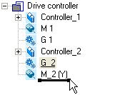
Similar to the folder view in the Windows Explorer, the project structure shows the individual machine components in the form of a tree topology:
•If you select a project element and then change to the workspace, the project element is still shown on a grey background and is underlined at the same time.
•Like this you can clearly see which project element the active workspace belongs to.
•By clicking the  /
/  icons, sub-elements can be shown / hidden.
: Project root |
• In the workspace, the properties and |
|
settings of the currently selected element/ |
|
device are shown and can be edited there. |
[3-1] Example for the hierarchical representation of the project structure in the Project tree
Tip!
You can alter the width and height of the Project view by using the mouse pointer to shift the screen divider between the Project view and the Workspace or between the Project view and the Message window.
By clicking with the right-hand mouse button, you can open a Context menu containing functions relevant to the elements.
18 |
Lenze · Engineer · 2.13 EN - 10/2014 |

User interface
Project structure (project tree)
_ _ _ _ _ _ _ _ _ _ _ _ _ _ _ _ _ _ _ _ _ _ _ _ _ _ _ _ _ _ _ _ _ _ _ _ _ _ _ _ _ _ _ _ _ _ _ _ _ _ _ _ _ _ _ _ _ _ _ _ _ _ _ _
3.3.1History of the preselected elements
All elements selected in the Project view during project processing are stored in a "history".
Note!
The history is emptied automatically when the project is closed, i.e. the history is always empty when you open a project.
The  /
/  buttons in the Toolbar jump to the project element selected previously / next.
Tip!
If the Project tree contains multiple devices, use  to return to the component edited last (e.g. a controller).
•If you click the arrow, , next to the  /
/  buttons, a selection list including the elements selected last is available.
•Every entry is provided in the following form: "project name: element name".
3.3.2General editing functions in the project view
The following processing functions apply to all elements in the Project view.Drag element (cut & paste) ( 19)
Duplicate element (copy & paste) ( 20)Delete element ( 20)
Rename element ( 20)
Drag element (cut & paste)
1.Select the element to be shifted including all subelements.
2.Click and hold the element with your left mouse button and drag it to the desired position. The current position of the element is displayed in one of the following manners:
•Highlighting the respective element:
The element to be shifted becomes the sub-element of the highlighted element. This behaviour corresponds to the following command chain: Edit Cut, and then Edit Paste.
Lenze · Engineer · 2.13 EN - 10/2014 |
19 |
User interface
Project structure (project tree)
_ _ _ _ _ _ _ _ _ _ _ _ _ _ _ _ _ _ _ _ _ _ _ _ _ _ _ _ _ _ _ _ _ _ _ _ _ _ _ _ _ _ _ _ _ _ _ _ _ _ _ _ _ _ _ _ _ _ _ _ _ _ _ _
• Element representation as horizontal bar:
The shifted element is positioned as desired between the two adjacent elements. The order of elements of the same level can be changed in the Project tree:
or
1.Select the element to be shifted including all subelements.
2.Select menu command Edit Cut.
3.Select the element into which the element cut before is to be pasted.
4.Select menu command Edit Insert.
Duplicate element (copy & paste)
1.Select the element which is to be copied including all subelements.
2.Select menu command Edit Copy.
3.Select the element into which the element copied before is to be pasted.
4.Select menu command Edit Insert.
Delete element
1.Select the element to be deleted including all subelements.
2.Select menu command Edit Delete or press the <Del> button in order to delete the element selected.
Rename element
1.Select the element to be renamed.
2.Select menu command Edit Rename or press the <F2> function key.
3.Enter new name.
4.Press the <input key> to accept the new name.
3.3.3Shortcuts in the project view
Tip!
As an alternative to directly selecting elements with the help of the mouse pointer, you can use keyboard shortcuts (for example, if you are running »Engineer« on a notebook). This enables faster movement within the Project view in order to select elements for editing.
You can use the following shortcuts for navigating within the Project view if an element is focused on in the Project view:
20 |
Lenze · Engineer · 2.13 EN - 10/2014 |
User interface
Workspace
_ _ _ _ _ _ _ _ _ _ _ _ _ _ _ _ _ _ _ _ _ _ _ _ _ _ _ _ _ _ _ _ _ _ _ _ _ _ _ _ _ _ _ _ _ _ _ _ _ _ _ _ _ _ _ _ _ _ _ _ _ _ _ _
Shortcut |
Function |
|
<PG UP> |
Browsing upwards in the Project tree. |
|
<PG DN> |
Browsing downwards in the Project tree. |
|
<UP ARROW> |
Selection of the next element up. |
|
<DOWN ARROW> |
Selection of the next element down. |
|
<LEFT ARROW> |
Depending on the symbol shown in front of the element: |
|
|
|
|
|
/ |
Selection of the higher-level/lower-level element in the hierarchy. |
<RIGHT ARROW |
Depending on the symbol shown in front of the element: |
|
|
|
|
|
/ |
Selection of the higher-level/lower-level element in the hierarchy. |
<BACKSPACE> |
Selection of the higher-level element in the hierarchy in each case. |
|
<POS1> |
Selection of the first project element. |
|
<END> |
Selection of the last (shown) project element. |
|
|
|
|
Tip!
In order to focus on an element in the Project view, click on a project element or press the <Tab> key until you reach the desired element.
3.3.4Project root
The project root  is the topmost element in the Project tree (root element). The name corresponds to the file name of the project.
•If the project root is selected, the tabs including general project properties are visible in the workspace.
Tab |
Function |
Components |
Tabulates all components inserted into the project. |
|
• The properties of the respective component are visible (device type, |
|
firmware version, communication path) as well as the structural |
|
integration in the form of system modules/axes. |
Applications |
Tabulates all applications inserted into the project. |
|
• The assignment to system modules/axes is visible. |
Data logger |
The data logger serves to record the temporal course of parameter values |
|
and display it as a line diagram. Data logger ( 111) |
|
• Note: For using this function, an online connection to the desired device |
|
is required! |
Documentation |
Provides the opportunity to enter detailed information on the project and |
|
the projected machine plant. |
|
• Notes and file attachments can be added to each project element. |
|
Documentation - Add project details ( 71) |
Protection |
Settings for protecting the safe configuration |
|
• Assign a project-related password for protecting the safe configuration |
|
(tab Safe configuration, safe parameters. Protecting safe parameters - |
|
project-related password entry ( 74) |
3.4Workspace
The workspace (area ) has various tabs which show the properties and settings of the project element currently selected in the project tree. A project element can be for instance a device: Servo Drives 9400 HighLine.
Lenze · Engineer · 2.13 EN - 10/2014 |
21 |
User interface
Workspace
_ _ _ _ _ _ _ _ _ _ _ _ _ _ _ _ _ _ _ _ _ _ _ _ _ _ _ _ _ _ _ _ _ _ _ _ _ _ _ _ _ _ _ _ _ _ _ _ _ _ _ _ _ _ _ _ _ _ _ _ _ _ _ _
Tip!
The representation of the tabs in the workspace depends on the selected project element / device type.
You can alter the width and height of the Workspace by using the mouse pointer to move the screen divider between the Project view and the Workspace or between the Workspace and the Message window as required.
Parameterising & configuring the devices ( 132)
3.4.1Displaying parameter values
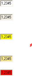
Device parameter settings shown in the workspace of the »Engineer« (e.g. in the Parameters tab for a device) are displayed with different background colours with the following meaning:
Colour |
Example |
Meaning |
Offline representation |
|
|
White |
|
Offline parameter |
|
|
• The device is not connected "online" with the »Engineer«. The "offline" parameter |
|
|
value set in the project is displayed. |
Light grey |
|
Offline display parameter |
|
|
• So-called "display parameters" are parameters which are only used to show |
|
|
status information and actual values and which feature a read-only access. |
Online representation |
|
|
Yellow |
|
Online parameter (value can be changed) |
|
|
• The device is connected "online" with the »Engineer«. The current parameter |
|
|
value of the device is displayed. |
|
|
• The symbol in front of a parameter value indicates that the value in the device |
|
|
differs from the parameter value set in the project. |
Pale yellow |
|
Online display parameter (read only) |
|
|
• The device is "online", i.e. connected to »Engineer«. The current parameter value |
|
|
of a display parameter of the device is shown. |
Red |
|
Communication error (time-out) |
|
|
• Communication to a device is interrupted, the online parameter could not be |
|
|
read out of the device within a certain time. |
|
|
|
22 |
Lenze · Engineer · 2.13 EN - 10/2014 |
User interface
Status information
_ _ _ _ _ _ _ _ _ _ _ _ _ _ _ _ _ _ _ _ _ _ _ _ _ _ _ _ _ _ _ _ _ _ _ _ _ _ _ _ _ _ _ _ _ _ _ _ _ _ _ _ _ _ _ _ _ _ _ _ _ _ _ _
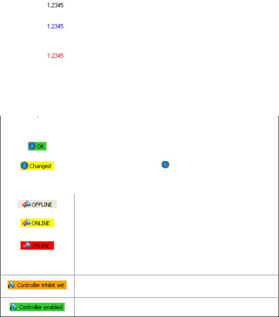
If you edit a parameter value in an input field, you can see from the colour of the text whether the altered value has already been integrated into the project or the device and is within the valid range.
Colour |
Example |
Meaning |
Black |
|
Parameter value that is within the valid range and that has already been integrated |
|
|
into the project or device. |
|
|
|
Blue |
|
Altered parameter value that has not yet been integrated into the project or the |
|
|
device. |
|
|
• By pressing the <input key>, you accept the altered value. |
|
|
• You can reject the change by pressing the <ESC> key. |
Red |
|
Changed parameter value which is outside the valid range. |
|
|
• You can reject the change by pressing the <ESC> key. |
|
|
|
3.5Status information
Information on the status of the project and devices/applications.
Information |
Meaning |
|
Project status |
|
|
|
|
|
|
All project information is up to date. |
|
|
• The project element selected in the Project tree does not have to be updated. |
|
|
|
|
|
The project contains unsaved changes. |
button in the Toolbar. Build project ( 76) |
|
• Build the project by pressing the |
|
|
|
|
|
|
|
Device status |
|
|
|
|
|
|
The device is offline. |
|
|
• No online connection to the device. |
|
|
|
|
|
Active online connection to the device. |
|
|
• The »Engineer« communicates with device via a bus connection. Establishing |
|
|
an online connection ( 75) |
|
|
Active online connection is interrupted. |
|
|
• An established online connection between the device and the »Engineer« is |
|
|
interrupted (communication error). |
|
|
|
|
DDCMP:/ |
Device-dependent access path |
|
|
• The access path depends on the respective bus connection. |
|
The controller is inhibited.
•The controller inhibit is set. Move the mouse pointer over the status information of the controller in the status line to display the source of the controller inhibit.
The controller is enabled.
Depending on the device connection used, more information can be displayed in the status line, as for instance the application status or unsaved changed of the parameter set.
Lenze · Engineer · 2.13 EN - 10/2014 |
23 |
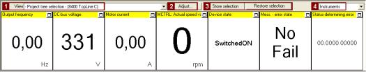
User interface
Monitor: Monitoring parameters
_ _ _ _ _ _ _ _ _ _ _ _ _ _ _ _ _ _ _ _ _ _ _ _ _ _ _ _ _ _ _ _ _ _ _ _ _ _ _ _ _ _ _ _ _ _ _ _ _ _ _ _ _ _ _ _ _ _ _ _ _ _ _ _
3.6Monitor: Monitoring parameters
In the Monitor area below the project view and workspace, the parameters of a device to be selected can be displayed as display parameters. This is reasonable, for instance, for monitoring certain parameters for diagnostic purposes.
3.6.1Show monitor window: Accept parameters/type of presentation
How to show the monitor window:
1.Click the  Monitor tab at the bottom of the user window.
2.Select the desired monitor window in the  View list field:
•-Project tree selection-: The monitor window always shows the parameters for device currently marked in the project tree.
•System: Multi-device monitor window with your compiled parameters for several devices of the automation system.
•Monitor window for a certain device. This leaves the focus on this device although a different device has been marked in the project tree.
•The monitor window is preconfigured with display parameters. The display parameters visible in the monitor window can be changed by clicking the  Adjust button.
Tip!
Increase individual display parameter: By clicking the window symbol in the top right display field, you show a display parameter across the entire width of the monitor window. For reducing it again, click the displayed window icon . This serves to show all display parameters again in the monitor window.
Using the parameter compilation for another device
Using the  Store selection and Restore selection buttons, you can use the parameter compilation of a monitor window for another device in the same project.
•After a monitor window has been created with device 1, click the Store selection button.
•Mark the desired device 2 in the project tree the application is to apply to as well.
•Click the Restore selection button to accept the parameter selection for the monitor window for device 2.
Change type of presentation: Graphic or tabular
The list field  changes the type of presentation: Graphic as Instruments or tabular as single- column/two-column list.
24 |
Lenze · Engineer · 2.13 EN - 10/2014 |
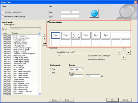
User interface
Monitor: Monitoring parameters
_ _ _ _ _ _ _ _ _ _ _ _ _ _ _ _ _ _ _ _ _ _ _ _ _ _ _ _ _ _ _ _ _ _ _ _ _ _ _ _ _ _ _ _ _ _ _ _ _ _ _ _ _ _ _ _ _ _ _ _ _ _ _ _
3.6.2Adapt monitor window: Show parameters graphically (instruments)
The instruments option serves to present your requested parameters graphically.
Tip!
Any value from the parameter list (All parameters tab) of a device can be transferred to the monitor window via right-click: Command: Add to monitor window
How to add the parameters to the monitor window:
1.Select the desired monitor window:
•Select the monitor window to be configured in the View list field (above the monitor window.
2.Click the Adapt button:
•Click the display field you want to configure in the area. The currently selected display field is highlighted by a blue frame.
3.In the area , select the parameter from all parameters of the device ...
... to be displayed in the display field of the monitor window (area ).
...by clicking the arrow key  /undoing the selection by using the arrow key
  . In order to remove all parameters from the monitor window, use the double arrow key
  .
.
•In order that only certain parameters are visible in the area , activate the corresponding filter options.
•Activate the in menu groups control field to arrange the parameters according to menu groups.
4.Repeat the steps 1 to 4 to display more parameters in the display fields in area (one parameter each per display field is possible).
Lenze · Engineer · 2.13 EN - 10/2014 |
25 |
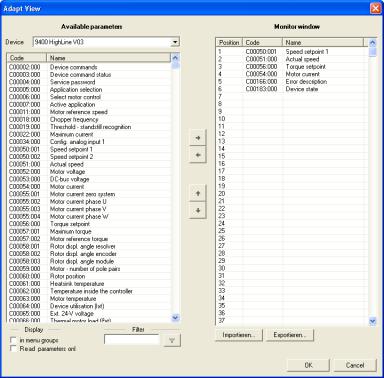
User interface
Monitor: Monitoring parameters
_ _ _ _ _ _ _ _ _ _ _ _ _ _ _ _ _ _ _ _ _ _ _ _ _ _ _ _ _ _ _ _ _ _ _ _ _ _ _ _ _ _ _ _ _ _ _ _ _ _ _ _ _ _ _ _ _ _ _ _ _ _ _ _
5.In the field, the Import/Export buttons serve to import/export composed monitor views. This serves, for instance, to use them in another »Engineer« project.
6.Press OK to transfer the selection to the monitor window.
3.6.3Adapt monitor window: Present parameters graphically (list)
The instruments option serves to present your requested parameters in table form in the monitor window.
How to add the parameters to the monitor window:
1.In the View list field, select the Monitor window to be configured.
2.Click the Adapt button to open the Adapt view dialog box.
3.Go to area and select the parameters to be transferred to the monitor window.
•Multi-selection of parameters shown one above the other: Hold down the <CTRL> key and highlight the parameters.
•Multi-selection of individual parameters: Hold down the <SHIFT> key and highlight the desired parameters individually.
•In order that only certain parameters are visible in the area, optionally activate the corresponding filters .
•Activate the in menu groups control field to arrange the parameters according to menu groups.
26 |
Lenze · Engineer · 2.13 EN - 10/2014 |
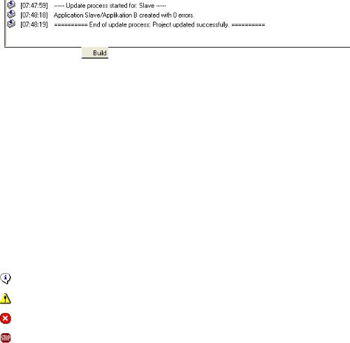
User interface
Create
_ _ _ _ _ _ _ _ _ _ _ _ _ _ _ _ _ _ _ _ _ _ _ _ _ _ _ _ _ _ _ _ _ _ _ _ _ _ _ _ _ _ _ _ _ _ _ _ _ _ _ _ _ _ _ _ _ _ _ _ _ _ _ _
4.Select the highlighted parameters (area ) by using the arrow key  /undoing the selection by using the arrow key
  . In order to remove all parameters from the monitor window, use the double arrow key
  .
.
As an alternative, press the  button to open a GDC file which includes the required parameter selection.
•Field shows the parameters selected for display.
•Press OK.
5.In the field, the Import/Export buttons serve to import/export composed monitor views. This serves, for instance, to use them in another »Engineer« project.
6.PressOk to add the selection to the monitor window.
3.7Create
The Build tab shows information on the individual creation and updating processes. Build project
( 76)
3.8User menu
The User menu tab shows the selection of parameters compiled by the user.
More information on how to create a user menu can be found in the following section: User menu ( 170)
3.9Messages
The Message window displays status and error messages relating to an executed program operation or the current status of the program.
Icon |
Time stamp |
Text |
|
[hh.mm.ss] |
Information text |
|
|
|
|
|
Note |
|
|
|
|
|
Error text |
|
|
|
|
|
Program error text |
|
|
|
Context menu
The following commands can be called in the message window via right-click:
Lenze · Engineer · 2.13 EN - 10/2014 |
27 |
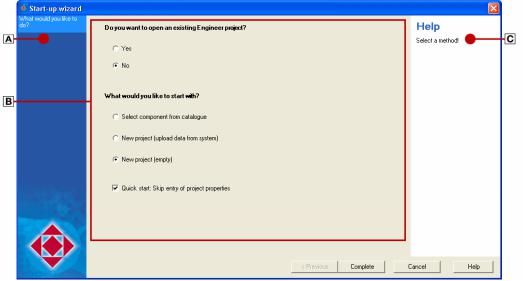
User interface
Wizards
_ _ _ _ _ _ _ _ _ _ _ _ _ _ _ _ _ _ _ _ _ _ _ _ _ _ _ _ _ _ _ _ _ _ _ _ _ _ _ _ _ _ _ _ _ _ _ _ _ _ _ _ _ _ _ _ _ _ _ _ _ _ _ _
Command |
Function |
Delete |
Delete all messages in the message window. |
Display |
Submenu to select the elements to be displayed. |
Copy list |
Copy all messages to the clipboard. |
Copy message |
Copy the selected message to the clipboard. |
|
|
Tip!
Using the mouse pointer, the height of the Message window can be changed by dragging the screen divider between Workspace and Message window up or down.
3.10Wizards
The »Engineer« is provided with several "wizards", e.g. for creating a project or setting up and configuring a network.
•The wizards are structured as follows. Select step by step the desired settings:
•Area shows within which step of the wizard you are right now.
•Area contains the main dialog box for entering the data and selecting the desired options.
•Area displays further information and input requests for the respective step.
28 |
Lenze · Engineer · 2.13 EN - 10/2014 |
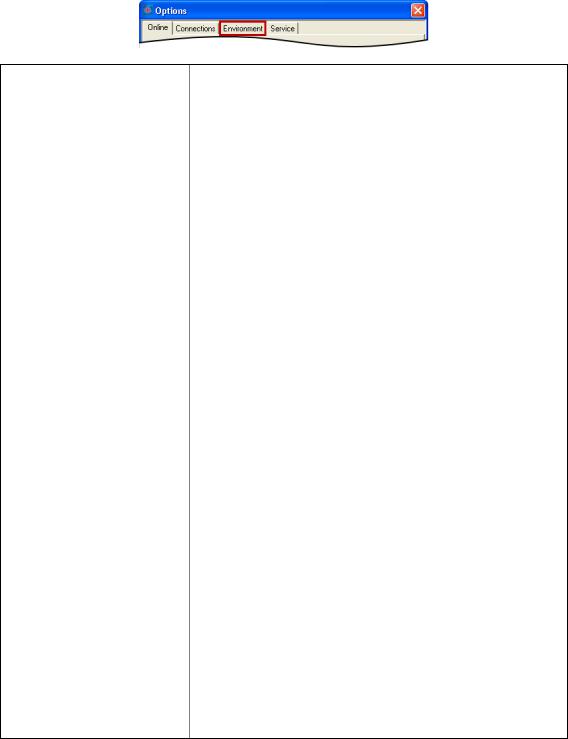
User interface
Options for the representation/project memory location
_ _ _ _ _ _ _ _ _ _ _ _ _ _ _ _ _ _ _ _ _ _ _ _ _ _ _ _ _ _ _ _ _ _ _ _ _ _ _ _ _ _ _ _ _ _ _ _ _ _ _ _ _ _ _ _ _ _ _ _ _ _ _ _
3.11Options for the representation/project memory location
Via the Tools Options menu command you open the Options dialog box. In this dialog box you can carry out general settings for the user interface in the Environment tab.
•In the Environment tab general settings can be edited.
•The settings are not a project property. Thus the settings are maintained for the following »Engineer« projects.
Option |
Description |
• Activate confirmation prompt |
Activate/deactivate confirmation prompt that is shown when components |
when deleting components |
are deleted. |
|
• If this option is deactivated, the »Engineer« directly deletes the desired |
|
component without a confirmation prompt. |
|
|
• Register external applications |
Specifies that the »Engineer« automatically writes the required entries into |
automatically |
the Windows registry to start external programs. |
|
• Like this the external program is registered for use in the »Engineer« and |
|
can thus be called by the »Engineer«. Registration is effected in |
|
accordance with the general Windows operating system standards. |
|
• This option is activated by default. |
|
Example: |
|
When a Servo Drive 9400 HighLine is updated, the »Engineer« calls the »PLC |
|
Designer« to compile the program code which was previously created from |
|
the function block interconnection. |
|
On the Engineering PC several versions of »Engineer« and/or the »PLC |
|
Designer« can be installed. When the option is activated, the »Engineer« |
|
automatically ensures that the "suitable" (expected) »PLC Designer« version |
|
is used for the compilation process. |
|
Note: |
|
If unexpected malfunction on your system occurs by this procedure, you can |
|
deactivate this option. |
|
For instance administrated access authorisation can prevent the »Engineer« |
|
from writing into the registry. |
|
In order to ensure that the external programs can be called by the |
|
»Engineer«, you then have to make sure that after installing the »Engineer« |
|
no other version of the program to be called by the »Engineer« has been |
|
installed on your Engineering PC. Otherwise malfunction or an unexpected |
|
response of the controller may result! |
|
|
• Change representation of the |
Specify the form of representation of the Project view bar: Filtering the |
Project view bar |
project tree. |
|
• For instance, the Project view bar can be masked out to increase the size |
|
of the Workspace. User interface ( 13) |
• Standard memory location for |
Specify the standard memory location for the creation of »Engineer« |
»Engineer« projects |
projects |
|
• The standard memory location can also be defined when a new project is |
|
created. Updating projects while opening them: Adapting project file |
|
from previous version ( 39) |
• Representation of descriptive |
Specify the type of representation of the descriptive texts. |
texts |
• The standard setting is "simple and self-explanatory". By this the |
|
respective descriptive text is reduced to the essential. |
|
• "Formally more clearly" provides further information. Hence, the |
|
descriptive texts are written in greater detail. |
|
• The option for instance has a (device-independent) effect on all codes and |
|
selection texts in the »Engineer«, which contain further descriptive texts. |
|
• The option will become effective after an »Engineer« restart. |
Lenze · Engineer · 2.13 EN - 10/2014 |
29 |
Getting started: creating a project
_ _ _ _ _ _ _ _ _ _ _ _ _ _ _ _ _ _ _ _ _ _ _ _ _ _ _ _ _ _ _ _ _ _ _ _ _ _ _ _ _ _ _ _ _ _ _ _ _ _ _ _ _ _ _ _ _ _ _ _ _ _ _ _
4 |
Getting started: creating a project |
Projects are created in the »Engineer« to show the machine/system concept in the project tree. In this project file, all parameterisation and configuration settings of the automation system are saved.
•When you start the »Engineer«, no project is loaded at first. The Start-up wizard enables ...
•... you to open existing projects. Opening the project file ( 38)
•... you to create new projects. Updating projects while opening them: Adapting project file from previous version ( 39)
30 |
Lenze · Engineer · 2.13 EN - 10/2014 |
Loading...