


 Loading...
Automation Systems
Controller-based
Automation
CANopen® _ _ _ _ _ _ _ _ _ _ _ _ _ _ _ _ _ _ _ _ _ _ _ _ _ _ _ _ _ _ _ _ |
Communication Manual |
DE |
Ä.O5÷ä 13462098
L
Contents
_ _ _ _ _ _ _ _ _ _ _ _ _ _ _ _ _ _ _ _ _ _ _ _ _ _ _ _ _ _ _ _ _ _ _ _ _ _ _ _ _ _ _ _ _ _ _ _ _ _ _ _ _ _ _ _ _ _ _ _ _ _ _ _
1 |
About this documentation _ _ _ _ _ _ _ _ _ _ _ _ _ _ _ _ _ _ _ _ _ _ _ _ _ _ _ _ _ _ _ _ _ _ _ _ _ _ _ |
5 |
|||
1.1 |
Document history |
_ _ _ _ _ _ _ _ _ _ _ _ _ _ _ _ _ _ _ _ _ _ _ _ _ _ _ _ _ _ _ _ _ _ _ _ _ _ _ _ _ _ _ _ |
7 |
||
1.2 |
Conventions used |
_ _ _ _ _ _ _ _ _ _ _ _ _ _ _ _ _ _ _ _ _ _ _ _ _ _ _ _ _ _ _ _ _ _ _ _ _ _ _ _ _ _ _ _ |
8 |
||
1.3 |
Terminology used |
_ _ _ _ _ _ _ _ _ _ _ _ _ _ _ _ _ _ _ _ _ _ _ _ _ _ _ _ _ _ _ _ _ _ _ _ _ _ _ _ _ _ _ _ |
9 |
||
1.4 |
Definition of the notes used |
_ _ _ _ _ _ _ _ _ _ _ _ _ _ _ _ _ _ _ _ _ _ _ _ _ _ _ _ _ _ _ _ _ _ _ _ _ _ |
10 |
||
2 |
Safety instructions _ _ _ _ _ _ _ _ _ _ _ _ _ _ _ _ _ _ _ _ _ _ _ _ _ _ _ _ _ _ _ _ _ _ _ _ _ _ _ _ _ _ _ _ |
11 |
|||
3 |
Controller-based Automation: Central motion control _ _ _ _ _ _ _ _ _ _ _ _ _ _ _ _ _ _ _ _ _ _ _ _ |
12 |
|||
4 |
System bus (CAN) / CANopen _ _ _ _ _ _ _ _ _ _ _ _ _ _ _ _ _ _ _ _ _ _ _ _ _ _ _ _ _ _ _ _ _ _ _ _ _ _ |
15 |
|||
4.1 |
CANopen (Logic) / CANopen (Motion) _ _ _ _ _ _ _ _ _ _ _ _ _ _ _ _ _ _ _ _ _ _ _ _ _ _ _ _ _ _ _ _ _ |
16 |
|||
4.2 |
Field devices _ _ _ _ _ _ _ _ _ _ _ _ _ _ _ _ _ _ _ _ _ _ _ _ _ _ _ _ _ _ _ _ _ _ _ _ _ _ _ _ _ _ _ _ _ _ _ |
17 |
|||
4.3 |
CANopen hardware for Lenze Controllers _ _ _ _ _ _ _ _ _ _ _ _ _ _ _ _ _ _ _ _ _ _ _ _ _ _ _ _ _ _ _ |
18 |
|||
4.4 |
Lenze Engineering tools _ _ _ _ _ _ _ _ _ _ _ _ _ _ _ _ _ _ _ _ _ _ _ _ _ _ _ _ _ _ _ _ _ _ _ _ _ _ _ _ _ |
19 |
|||
5 |
Technical data _ _ _ _ _ _ _ _ _ _ _ _ _ _ _ _ _ _ _ _ _ _ _ _ _ _ _ _ _ _ _ _ _ _ _ _ _ _ _ _ _ _ _ _ _ _ |
20 |
|||
5.1 |
General data _ _ _ _ _ _ _ _ _ _ _ _ _ _ _ _ _ _ _ _ _ _ _ _ _ _ _ _ _ _ _ _ _ _ _ _ _ _ _ _ _ _ _ _ _ _ _ |
20 |
|||
5.2 |
Technical data of the MC-CAN2 communication card _ _ _ _ _ _ _ _ _ _ _ _ _ _ _ _ _ _ _ _ _ _ _ _ _ |
21 |
|||
5.3 |
Bus cable specification _ _ _ _ _ _ _ _ _ _ _ _ _ _ _ _ _ _ _ _ _ _ _ _ _ _ _ _ _ _ _ _ _ _ _ _ _ _ _ _ _ |
21 |
|||
5.4 |
Bus cable length _ _ _ _ _ _ _ _ _ _ _ _ _ _ _ _ _ _ _ _ _ _ _ _ _ _ _ _ _ _ _ _ _ _ _ _ _ _ _ _ _ _ _ _ _ |
22 |
|||
|
5.4.1 |
Total cable length |
_ _ _ _ _ _ _ _ _ _ _ _ _ _ _ _ _ _ _ _ _ _ _ _ _ _ _ _ _ _ _ _ _ _ _ _ _ _ _ |
22 |
|
|
5.4.2 |
Segment cable length _ _ _ _ _ _ _ _ _ _ _ _ _ _ _ _ _ _ _ _ _ _ _ _ _ _ _ _ _ _ _ _ _ _ _ _ _ |
22 |
||
|
5.4.3 |
Use of repeaters _ _ _ _ _ _ _ _ _ _ _ _ _ _ _ _ _ _ _ _ _ _ _ _ _ _ _ _ _ _ _ _ _ _ _ _ _ _ _ _ |
23 |
||
6 |
Planning the CANopen network _ _ _ _ _ _ _ _ _ _ _ _ _ _ _ _ _ _ _ _ _ _ _ _ _ _ _ _ _ _ _ _ _ _ _ _ |
25 |
|||
6.1 |
COB-IDs acc. to DS301 _ _ _ _ _ _ _ _ _ _ _ _ _ _ _ _ _ _ _ _ _ _ _ _ _ _ _ _ _ _ _ _ _ _ _ _ _ _ _ _ _ _ |
26 |
|||
6.2 |
Example of an overview screen _ _ _ _ _ _ _ _ _ _ _ _ _ _ _ _ _ _ _ _ _ _ _ _ _ _ _ _ _ _ _ _ _ _ _ _ _ |
27 |
|||
6.3 |
Device specifications of the field devices _ _ _ _ _ _ _ _ _ _ _ _ _ _ _ _ _ _ _ _ _ _ _ _ _ _ _ _ _ _ _ _ |
28 |
|||
|
6.3.1 |
Special features of the 9400 Servo Drives _ _ _ _ _ _ _ _ _ _ _ _ _ _ _ _ _ _ _ _ _ _ _ _ _ _ |
29 |
||
|
6.3.2 |
Special features of the 8400 Inverter Drives _ _ _ _ _ _ _ _ _ _ _ _ _ _ _ _ _ _ _ _ _ _ _ _ _ |
30 |
||
|
6.3.3 Special features of the I/O system 1000 (EPM-Sxxx) _ _ _ _ _ _ _ _ _ _ _ _ _ _ _ _ _ _ _ _ _ |
31 |
|||
6.4 |
Special case: Delayed switch-on of one or more slaves _ _ _ _ _ _ _ _ _ _ _ _ _ _ _ _ _ _ _ _ _ _ _ _ |
32 |
|||
7 |
Preparing the field devices _ _ _ _ _ _ _ _ _ _ _ _ _ _ _ _ _ _ _ _ _ _ _ _ _ _ _ _ _ _ _ _ _ _ _ _ _ _ _ |
33 |
|||
7.1 |
Installing field devices _ _ _ _ _ _ _ _ _ _ _ _ _ _ _ _ _ _ _ _ _ _ _ _ _ _ _ _ _ _ _ _ _ _ _ _ _ _ _ _ _ _ |
33 |
|||
7.2 |
Setting node addresses and baud rate _ _ _ _ _ _ _ _ _ _ _ _ _ _ _ _ _ _ _ _ _ _ _ _ _ _ _ _ _ _ _ _ _ |
33 |
|||
7.3 |
Connecting the Engineering PC to the Lenze Controller _ _ _ _ _ _ _ _ _ _ _ _ _ _ _ _ _ _ _ _ _ _ _ _ |
34 |
|||
2 |
Lenze · Controller-based Automation · CANopen® Communication Manual · DMS 6.3 EN · 04/2014 · TD17 |
Contents
_ _ _ _ _ _ _ _ _ _ _ _ _ _ _ _ _ _ _ _ _ _ _ _ _ _ _ _ _ _ _ _ _ _ _ _ _ _ _ _ _ _ _ _ _ _ _ _ _ _ _ _ _ _ _ _ _ _ _ _ _ _ _ _
8 |
Commissioning of the CANopen Logic bus _ _ _ _ _ _ _ _ _ _ _ _ _ _ _ _ _ _ _ _ _ _ _ _ _ _ _ _ _ _ _ |
36 |
||||
8.1 |
Sample projects (Application Samples) _ _ _ _ _ _ _ _ _ _ _ _ _ _ _ _ _ _ _ _ _ _ _ _ _ _ _ _ _ _ _ _ _ |
36 |
||||
8.2 |
Overview of the commissioning steps _ _ _ _ _ _ _ _ _ _ _ _ _ _ _ _ _ _ _ _ _ _ _ _ _ _ _ _ _ _ _ _ _ |
37 |
||||
8.3 |
Create a project folder _ _ _ _ _ _ _ _ _ _ _ _ _ _ _ _ _ _ _ _ _ _ _ _ _ _ _ _ _ _ _ _ _ _ _ _ _ _ _ _ _ _ |
38 |
||||
8.4 |
Commissioning the field devices _ _ _ _ _ _ _ _ _ _ _ _ _ _ _ _ _ _ _ _ _ _ _ _ _ _ _ _ _ _ _ _ _ _ _ _ |
39 |
||||
8.5 |
Creating a PLC program with a target system (Logic) |
_ _ _ _ _ _ _ _ _ _ _ _ _ _ _ _ _ _ _ _ _ _ _ _ _ |
40 |
|||
8.6 |
Configuring the communication parameters |
_ _ _ _ _ _ _ _ _ _ _ _ _ _ _ _ _ _ _ _ _ _ _ _ _ _ _ _ _ |
42 |
|||
8.7 |
Importing missing devices / device description files |
_ _ _ _ _ _ _ _ _ _ _ _ _ _ _ _ _ _ _ _ _ _ _ _ _ |
44 |
|||
8.8 |
Creating a control configuration (adding field devices) _ _ _ _ _ _ _ _ _ _ _ _ _ _ _ _ _ _ _ _ _ _ _ _ |
45 |
||||
8.9 |
Setting of CAN parameters and PDO mapping |
_ _ _ _ _ _ _ _ _ _ _ _ _ _ _ _ _ _ _ _ _ _ _ _ _ _ _ _ |
50 |
|||
|
8.9.1 |
Cross communication between the slaves _ _ _ _ _ _ _ _ _ _ _ _ _ _ _ _ _ _ _ _ _ _ _ _ _ _ |
53 |
|||
|
8.9.2 Special features of the I/O system 1000 (EPM-Sxxx) _ _ _ _ _ _ _ _ _ _ _ _ _ _ _ _ _ _ _ _ _ |
54 |
||||
8.10 |
Creating the program code for controlling the Logic field device _ _ _ _ _ _ _ _ _ _ _ _ _ _ _ _ _ _ _ |
57 |
||||
8.11 |
Preparing the restart |
_ _ _ _ _ _ _ _ _ _ _ _ _ _ _ _ _ _ _ _ _ _ _ _ _ _ _ _ _ _ _ _ _ _ _ _ _ _ _ _ _ _ |
59 |
|||
|
8.11.1 |
Special features of the 9400 Servo Drives HighLine _ _ _ _ _ _ _ _ _ _ _ _ _ _ _ _ _ _ _ _ _ |
60 |
|||
|
8.11.2 Special features of the 8400 Inverter Drives |
_ _ _ _ _ _ _ _ _ _ _ _ _ _ _ _ _ _ _ _ _ _ _ _ _ |
60 |
|||
|
8.11.3 Special features of the I/O system 1000 (EPM-Sxxx) _ _ _ _ _ _ _ _ _ _ _ _ _ _ _ _ _ _ _ _ _ |
61 |
||||
8.12 |
Compiling the PLC program code _ _ _ _ _ _ _ _ _ _ _ _ _ _ _ _ _ _ _ _ _ _ _ _ _ _ _ _ _ _ _ _ _ _ _ _ |
64 |
||||
8.13 |
Logging in on the Lenze Controller with the »PLC Designer« _ _ _ _ _ _ _ _ _ _ _ _ _ _ _ _ _ _ _ _ _ |
64 |
||||
8.14 |
Starting the PLC program _ _ _ _ _ _ _ _ _ _ _ _ _ _ _ _ _ _ _ _ _ _ _ _ _ _ _ _ _ _ _ _ _ _ _ _ _ _ _ _ |
64 |
||||
8.15 |
Start parameters of the Servo Drives 9400 HighLine CiA 402 _ _ _ _ _ _ _ _ _ _ _ _ _ _ _ _ _ _ _ _ _ |
64 |
||||
9 |
Commissioning of the CANopen Motion bus _ _ _ _ _ _ _ _ _ _ _ _ _ _ _ _ _ _ _ _ _ _ _ _ _ _ _ _ _ |
65 |
||||
9.1 |
Sample projects (Application Samples) _ _ _ _ _ _ _ _ _ _ _ _ _ _ _ _ _ _ _ _ _ _ _ _ _ _ _ _ _ _ _ _ _ |
66 |
||||
9.2 |
Overview of the commissioning steps _ _ _ _ _ _ _ _ _ _ _ _ _ _ _ _ _ _ _ _ _ _ _ _ _ _ _ _ _ _ _ _ _ |
67 |
||||
9.3 |
Create a project folder _ _ _ _ _ _ _ _ _ _ _ _ _ _ _ _ _ _ _ _ _ _ _ _ _ _ _ _ _ _ _ _ _ _ _ _ _ _ _ _ _ _ |
68 |
||||
9.4 |
Commissioning the field devices _ _ _ _ _ _ _ _ _ _ _ _ _ _ _ _ _ _ _ _ _ _ _ _ _ _ _ _ _ _ _ _ _ _ _ _ |
69 |
||||
9.5 |
Creating a PLC program with target system (Motion) _ _ _ _ _ _ _ _ _ _ _ _ _ _ _ _ _ _ _ _ _ _ _ _ _ |
70 |
||||
9.6 |
Configuring the communication parameters |
_ _ _ _ _ _ _ _ _ _ _ _ _ _ _ _ _ _ _ _ _ _ _ _ _ _ _ _ _ |
72 |
|||
9.7 |
Creating a Motion task |
_ _ _ _ _ _ _ _ _ _ _ _ _ _ _ _ _ _ _ _ _ _ _ _ _ _ _ _ _ _ _ _ _ _ _ _ _ _ _ _ _ |
74 |
|||
9.8 |
Creating a control configuration _ _ _ _ _ _ _ _ _ _ _ _ _ _ _ _ _ _ _ _ _ _ _ _ _ _ _ _ _ _ _ _ _ _ _ _ |
78 |
||||
9.9 |
Parallel operation of two synchronised CAN buses _ _ _ _ _ _ _ _ _ _ _ _ _ _ _ _ _ _ _ _ _ _ _ _ _ _ |
82 |
||||
9.10 |
Setting SoftMotion parameters _ _ _ _ _ _ _ _ _ _ _ _ _ _ _ _ _ _ _ _ _ _ _ _ _ _ _ _ _ _ _ _ _ _ _ _ _ |
84 |
||||
9.11 |
Setting of CAN parameters and PDO mapping |
_ _ _ _ _ _ _ _ _ _ _ _ _ _ _ _ _ _ _ _ _ _ _ _ _ _ _ _ |
87 |
|||
9.12 |
Creating the program code for controlling the Motion field device _ _ _ _ _ _ _ _ _ _ _ _ _ _ _ _ _ |
90 |
||||
9.13 |
Preparing the restart |
_ _ _ _ _ _ _ _ _ _ _ _ _ _ _ _ _ _ _ _ _ _ _ _ _ _ _ _ _ _ _ _ _ _ _ _ _ _ _ _ _ _ |
90 |
|||
9.14 |
Compiling the PLC program code _ _ _ _ _ _ _ _ _ _ _ _ _ _ _ _ _ _ _ _ _ _ _ _ _ _ _ _ _ _ _ _ _ _ _ _ |
91 |
||||
9.15 |
Logging in on the Lenze Controller with the »PLC Designer« _ _ _ _ _ _ _ _ _ _ _ _ _ _ _ _ _ _ _ _ _ |
91 |
||||
9.16 |
Starting the PLC program _ _ _ _ _ _ _ _ _ _ _ _ _ _ _ _ _ _ _ _ _ _ _ _ _ _ _ _ _ _ _ _ _ _ _ _ _ _ _ _ |
91 |
||||
9.17 |
Start parameters of the Servo Drives 9400 HighLine CiA 402 _ _ _ _ _ _ _ _ _ _ _ _ _ _ _ _ _ _ _ _ _ |
91 |
||||
Lenze · Controller-based Automation · CANopen® Communication Manual · DMS 6.3 EN · 04/2014 · TD17 |
3 |
Contents
_ _ _ _ _ _ _ _ _ _ _ _ _ _ _ _ _ _ _ _ _ _ _ _ _ _ _ _ _ _ _ _ _ _ _ _ _ _ _ _ _ _ _ _ _ _ _ _ _ _ _ _ _ _ _ _ _ _ _ _ _ _ _ _
10 |
Mixed operation of CANopen and EtherCAT _ _ _ _ _ _ _ _ _ _ _ _ _ _ _ _ _ _ _ _ _ _ _ _ _ _ _ _ _ _ |
92 |
||
11 |
SM3_Drive_Lenze.lib function library _ _ _ _ _ _ _ _ _ _ _ _ _ _ _ _ _ _ _ _ _ _ _ _ _ _ _ _ _ _ _ _ _ |
93 |
||
12 |
Restarting the CAN bus _ _ _ _ _ _ _ _ _ _ _ _ _ _ _ _ _ _ _ _ _ _ _ _ _ _ _ _ _ _ _ _ _ _ _ _ _ _ _ _ _ |
94 |
||
13 |
Defining the minimum cycle time of the PLC project _ _ _ _ _ _ _ _ _ _ _ _ _ _ _ _ _ _ _ _ _ _ _ _ _ |
95 |
||
13.1 |
Determining the task utilisation of the application _ _ _ _ _ _ _ _ _ _ _ _ _ _ _ _ _ _ _ _ _ _ _ _ _ _ |
95 |
||
13.2 |
Optimising the system _ _ _ _ _ _ _ _ _ _ _ _ _ _ _ _ _ _ _ _ _ _ _ _ _ _ _ _ _ _ _ _ _ _ _ _ _ _ _ _ _ |
97 |
||
14 |
Diagnostics _ _ _ _ _ _ _ _ _ _ _ _ _ _ _ _ _ _ _ _ _ _ _ _ _ _ _ _ _ _ _ _ _ _ _ _ _ _ _ _ _ _ _ _ _ _ _ _ |
98 |
||
14.1 |
Logbook of the Lenze Controller _ _ _ _ _ _ _ _ _ _ _ _ _ _ _ _ _ _ _ _ _ _ _ _ _ _ _ _ _ _ _ _ _ _ _ _ |
98 |
||
14.2 |
"Status" tab of the connected field devices |
_ _ _ _ _ _ _ _ _ _ _ _ _ _ _ _ _ _ _ _ _ _ _ _ _ _ _ _ _ _ |
99 |
|
14.3 |
Diagnostic codes _ _ _ _ _ _ _ _ _ _ _ _ _ _ _ _ _ _ _ _ _ _ _ _ _ _ _ _ _ _ _ _ _ _ _ _ _ _ _ _ _ _ _ _ _ |
99 |
||
14.4 |
System bus configurator of the »Engineer« |
_ _ _ _ _ _ _ _ _ _ _ _ _ _ _ _ _ _ _ _ _ _ _ _ _ _ _ _ _ _ |
100 |
|
14.5 |
»PCAN view« for diagnostic purposes _ _ _ _ _ _ _ _ _ _ _ _ _ _ _ _ _ _ _ _ _ _ _ _ _ _ _ _ _ _ _ _ _ |
101 |
||
|
14.5.1 |
Monitor telegram traffic on the CANopen bus _ _ _ _ _ _ _ _ _ _ _ _ _ _ _ _ _ _ _ _ _ _ _ _ |
101 |
|
|
14.5.2 |
Setting all CANopen nodes to the "Operational" status _ _ _ _ _ _ _ _ _ _ _ _ _ _ _ _ _ _ _ |
103 |
|
14.6 |
Notes regarding the visualisation using »VisiWinNET« _ _ _ _ _ _ _ _ _ _ _ _ _ _ _ _ _ _ _ _ _ _ _ _ |
104 |
||
15 |
Parameter reference _ _ _ _ _ _ _ _ _ _ _ _ _ _ _ _ _ _ _ _ _ _ _ _ _ _ _ _ _ _ _ _ _ _ _ _ _ _ _ _ _ _ _ |
105 |
||
|
Index _ _ _ _ _ _ _ _ _ _ _ _ _ _ _ _ _ _ _ _ _ _ _ _ _ _ _ _ _ _ _ _ _ _ _ _ _ _ _ _ _ _ _ _ _ _ _ _ _ _ _ |
107 |
||
|
Your opinion is important to us _ _ _ _ _ _ _ _ _ _ _ _ _ _ _ _ _ _ _ _ _ _ _ _ _ _ _ _ _ _ _ _ _ _ _ _ _ |
109 |
||
4 |
Lenze · Controller-based Automation · CANopen® Communication Manual · DMS 6.3 EN · 04/2014 · TD17 |
1 About this documentation
_ _ _ _ _ _ _ _ _ _ _ _ _ _ _ _ _ _ _ _ _ _ _ _ _ _ _ _ _ _ _ _ _ _ _ _ _ _ _ _ _ _ _ _ _ _ _ _ _ _ _ _ _ _ _ _ _ _ _ _ _ _ _ _
1 |
About this documentation |
This documentation ...
•contains detailed information about the commissioning, configuration, and diagnostics of the CANopen® bus system as part of the Lenze automation system Controller-based Automation.
•is part of the "Controller-based Automation" manual collection. It consists of the following sets of documentation:
Documentation type |
Subject |
System manuals |
System overview/sample topologies |
|
• Controller-based Automation |
|
• Visualising |
Communication manuals |
Bus systems |
Online helps |
• Controller-based Automation EtherCAT® |
|
• Controller-based Automation CANopen® |
|
• Controller-based Automation PROFIBUS® |
|
• Controller-based Automation PROFINET® |
Reference manuals |
Lenze Controller: |
Online helps |
• Controller 3200 C |
|
• Controller c300 |
|
• Controller p300 |
|
• Controller p500 |
Software manuals |
Lenze Engineering Tools: |
Online helps |
• »PLC Designer«: Programming |
|
• »Engineer«: Inverter configuration |
|
• »VisiWinNET® Smart«: Visualisation |
|
• »Backup & Restore«: Back up/restore data |
|
|
5 |
Lenze · Controller-based Automation · CANopen® Communication Manual · DMS 6.3 EN · 04/2014 · TD17 |

1 About this documentation
_ _ _ _ _ _ _ _ _ _ _ _ _ _ _ _ _ _ _ _ _ _ _ _ _ _ _ _ _ _ _ _ _ _ _ _ _ _ _ _ _ _ _ _ _ _ _ _ _ _ _ _ _ _ _ _ _ _ _ _ _ _ _ _
More technical documentation for Lenze components
Further information on Lenze products which can be used in conjunction with Controller-based Automation can be found in the following sets of documentation:
Mounting & wiring
Mounting instructions
•Controller
•Communication cards (MC-xxx)
•I/O system 1000 (EPM-Sxxx)
•Inverter, Servo Drives
•Communication modules
Operating instructions
•Controller
•Servo system ECS (ECSxE, ECSxM)
Sample applications/Using application templates
Online help/software manuals
•Application Sample i700
•Application Samples
•ApplicationTemplate
Parameter setting, configuration, commissioning
Online help/reference manuals
•L-force Controller
•Inverter, Servo Drives
•I/O system 1000 (EPM-Sxxx)
Online help/communication manuals
•Bus systems
•Communication modules
Operating instructions
•Servo system ECS (ECSxE, ECSxM)
Symbols:
Printed documentation
Online help in the Lenze Engineering Tool (also available as PDF file at www.lenze.com.)
Tip!
Current documentation and software updates with regard to Lenze products can be found in the download area at:
www.lenze.com
Target group
This documentation is intended for persons who plan, install, commission and maintain the networking of devices as part of the Lenze automation system "Controller-based Automation".
Information on validity
The information provided in this documentation is valid for the Lenze automation system "Controller-based Automation" from version 3.
Screenshots/application examples
All screenshots in this documentation are application examples. Depending on the firmware version of the field devices and the software version of the Engineering tools installed (e.g. »PLC Designer« ), screenshots in this documentation may differ from the representation on the screen.
Lenze · Controller-based Automation · CANopen® Communication Manual · DMS 6.3 EN · 04/2014 · TD17 |
6 |
1 About this documentation
1.1Document history
_ _ _ _ _ _ _ _ _ _ _ _ _ _ _ _ _ _ _ _ _ _ _ _ _ _ _ _ _ _ _ _ _ _ _ _ _ _ _ _ _ _ _ _ _ _ _ _ _ _ _ _ _ _ _ _ _ _ _ _ _ _ _ _
1.1Document history
Version |
|
|
Description |
|
1.0 |
|
06/2008 |
TD17 |
First edition |
2.0 |
|
09/2008 |
TD17 |
Chapter "Mixed operation of CANopen and EtherCAT" ( 92) added. |
3.0 |
|
06/2009 |
TD17 |
General revision |
4.0 |
|
10/2009 |
TD17 |
General revision |
5.0 |
|
10/2010 |
TD17 |
Commissioning and configuration with the Lenze »PLC Designer« V3.x |
5.1 |
|
03/2011 |
TD17 |
• Chapter "Parallel operation of two synchronised CAN buses" ( 82) |
|
|
|
|
supplemented. |
|
|
|
|
• SoftMotion settings for Servo Drives 9400 and ECSxM supplemented. |
|
|
|
|
• References to Lenze sample projects for CANopen Logic field devices (device |
|
|
|
|
application + PLC program) added. |
|
|
|
|
Commissioning of the CANopen Logic bus ( 36) |
5.2 |
|
12/2011 |
TD17 |
Revision on the Lenze automation system"Controller-based Automation", |
|
|
|
|
release 3.2 |
5.3 |
|
07/2012 |
TD17 |
• Revision on the Lenze automation system"Controller-based Automation", |
|
|
|
|
release 3.3 |
|
|
|
|
• Information on the ECS servo system and »GDC« removed. |
6.0 |
|
11/2012 |
TD17 |
• General corrections |
|
|
|
|
• New layout |
6.1 |
|
03/2013 |
TD17 |
Revision on the Lenze automation system"Controller-based Automation", |
|
|
|
|
release 3.5 |
6.2 |
|
11/2013 |
TD17 |
Revision on the Lenze automation system"Controller-based Automation", |
|
|
|
|
release 3.6 |
6.3 |
|
04/2014 |
TD17 |
Revision on the Lenze automation system"Controller-based Automation", |
|
|
|
|
release 3.8 |
|
|
|
|
|
7 |
Lenze · Controller-based Automation · CANopen® Communication Manual · DMS 6.3 EN · 04/2014 · TD17 |
1 About this documentation
1.2Conventions used
_ _ _ _ _ _ _ _ _ _ _ _ _ _ _ _ _ _ _ _ _ _ _ _ _ _ _ _ _ _ _ _ _ _ _ _ _ _ _ _ _ _ _ _ _ _ _ _ _ _ _ _ _ _ _ _ _ _ _ _ _ _ _ _
1.2Conventions used
This documentation uses the following conventions to distinguish different types of information:
Type of information |
Identification |
Examples/notes |
|
Numbers |
|
|
|
Decimal |
Normal spelling |
Example: 1234 |
|
Decimal separator |
Point |
In general, the decimal point is used. |
|
|
|
Example: 1234.56 |
|
Hexadecimal |
0x[0 ... 9, A ... F] |
Example: 0x60F4 |
|
Binary |
0b[0, 1] |
Example: ’0b0110’ |
|
• Nibble |
|
Example: ’0b0110.0100’ |
|
Text |
|
|
|
Program name |
» « |
PC software |
|
|
|
Example: Lenze »Engineer« |
|
Window |
italics |
The message window... / The Options dialog box ... |
|
Variable name |
|
Setting bEnable to TRUE... |
|
Control element |
Bold |
The OK button ... / The Copy command ... / The Properties |
|
|
|
tab ... / The Name input field ... |
|
Sequence of menu |
|
If several successive commands are required for |
|
commands |
|
executing a function, the individual commands are |
|
|
|
separated from each other by an arrow: Select the |
|
|
|
command File Open to... |
|
Shortcut |
<Bold> |
Use <F1> to open the online help. |
|
|
|
|
|
|
|
If a key combination is required for a command, a "+" is |
|
|
|
placed between the key identifiers: With |
|
|
|
<Shift>+<ESC>... |
|
Program code |
Courier |
IF var1 < var2 THEN |
|
Keyword |
Courier bold |
a = a + 1 |
|
END IF |
|||
|
|
||
Hyperlink |
Underlined |
Optically highlighted reference to another topic. Can be |
|
|
|
activated with a mouse-click in this documentation. |
|
Icons |
|
|
|
Page reference |
( 8) |
Optically highlighted reference to another page. Can be |
|
|
|
activated with a mouse-click in this documentation. |
|
Step-by-step instructions |
|
Step-by-step instructions are marked by a pictograph. |
Lenze · Controller-based Automation · CANopen® Communication Manual · DMS 6.3 EN · 04/2014 · TD17 |
8 |

1 About this documentation
1.3Terminology used
_ _ _ _ _ _ _ _ _ _ _ _ _ _ _ _ _ _ _ _ _ _ _ _ _ _ _ _ _ _ _ _ _ _ _ _ _ _ _ _ _ _ _ _ _ _ _ _ _ _ _ _ _ _ _ _ _ _ _ _ _ _ _ _
1.3Terminology used
Term |
Meaning |
CAN |
CAN (Controller Area Network) is an asynchronous, serial fieldbus system. |
|
CANopen® is a communication protocol based on CAN. The Lenze system bus (CAN on board) |
|
operates with a subset of this communication protocol. |
|
CANopen® is a registered Community Trade Mark of the CAN User Organisation CiA® (CAN |
|
in Automation e. V.). |
Code |
Parameter for parameterising or monitoring the field device. The term is also referred to as |
|
"index" in common usage. |
Controller |
The controller is the central component of the automation system which controls the Logic |
|
and Motion functionalities (by means of the runtime software). |
|
The controller communicates with the field devices via the fieldbus. |
Engineering PC |
The Engineering PC and the Engineering tools installed serve to configure and parameterise |
|
the system. |
|
The Engineering PC communicates with the controller via Ethernet. |
Engineering tools |
Lenze software solutions for simply engineering in all phases: |
|
• »EASY Starter« |
|
• »Engineer« |
|
• »PLC Designer« |
|
• »WebConfig« |
|
• »VisiWinNET®« |
|
• »IPC Backup & Restore« |
|
Lenze Engineering tools ( 19) |
|
»PCAN view« is the basic version of the »PCAN explorer« program by PEAK System Technik |
|
GmbH for the diagnostics of CAN networks. |
|
EtherCAT® (Ethernet for Controller and Automation Technology) is an Ethernet-based |
|
fieldbus system which meets the application profile for industrial real-time systems. |
|
EtherCAT® is a registered trademark and patented technology, licensed by Beckhoff |
|
Automation GmbH, Germany. |
Fieldbus stations |
Lenze Controller and controller integrated into the bus system (CANopen) |
Field device |
|
PLC |
Programmable Logic Controller |
|
(German designation: SPS - Speicherprogrammierbare Steuerung) |
Subcode |
If a code contains several parameters, they are stored in so-called "subcodes". |
|
This manual uses a slash "/" as a separator between code and subcode (e.g. "C00118/3"). |
|
In normal usage, the term is also referred to as "Subindex". |
|
|
9 |
Lenze · Controller-based Automation · CANopen® Communication Manual · DMS 6.3 EN · 04/2014 · TD17 |

1 About this documentation
1.4Definition of the notes used
_ _ _ _ _ _ _ _ _ _ _ _ _ _ _ _ _ _ _ _ _ _ _ _ _ _ _ _ _ _ _ _ _ _ _ _ _ _ _ _ _ _ _ _ _ _ _ _ _ _ _ _ _ _ _ _ _ _ _ _ _ _ _ _
1.4Definition of the notes used
The following signal words and symbols are used in this documentation to indicate dangers and important information:
Safety instructions
Layout of the safety instructions:
Pictograph and signal word!
(characterises the type and severity of danger)
Note
(describes the danger and suggests how to prevent dangerous situations)
Pictograph |
Signal word |
Meaning |
|
Danger! |
Danger of personal injury through dangerous electrical voltage |
|
Reference to an imminent danger that may result in death or serious personal injury |
|
|
if the corresponding measures are not taken. |
|
|
Danger! |
Danger of personal injury through a general source of danger |
|
Reference to an imminent danger that may result in death or serious personal injury |
|
|
if the corresponding measures are not taken. |
|
|
Stop! |
Danger of damage to material assets |
|
Reference to a possible danger that may result in damage to material assets if the |
|
|
corresponding measures are not taken. |
|
Application notes |
|
|
|
|
|
Pictograph |
Signal word |
Meaning |
|
|
|
Note! Important note to ensure trouble-free operation
Tip! Useful tip for easy handling
|
Reference to other documentation |
|
Lenze · Controller-based Automation · CANopen® Communication Manual · DMS 6.3 EN · 04/2014 · TD17 |
10 |
2 Safety instructions
_ _ _ _ _ _ _ _ _ _ _ _ _ _ _ _ _ _ _ _ _ _ _ _ _ _ _ _ _ _ _ _ _ _ _ _ _ _ _ _ _ _ _ _ _ _ _ _ _ _ _ _ _ _ _ _ _ _ _ _ _ _ _ _
2 |
Safety instructions |
Observe the following safety instructions if you want to commission an inverter or a system with the Lenze Controller.
Read the documentation supplied with the system components carefully before you start commissioning the devices and the Lenze Controller!
The system manual contains safety instructions which must be observed!
Danger!
Risk of injury
There is risk of injury by ...
•unpredictable motor movements (e.g. an unintended direction of rotation, too high speeds, or jerky movement);
•impermissible operating states during the parameterisation while there is an active online connection to the device.
Possible consequences
Death or severe injuries
Protective measures
•If required, provide systems with installed inverters with additional monitoring and protective devices according to the safety regulations valid in each case (e.g. law on technical equipment, regulations for the prevention of accidents).
•During commissioning, maintain an adequate safety distance to the motor or the machine parts driven by the motor.
Stop!
Damage or destruction of machine parts
Damage or destruction of machine parts can be caused by ...
•unpredictable motor movements (e.g. an unintended direction of rotation, too high speeds, or jerky movement);
•impermissible operating states during the parameterisation while there is an active online connection to the device.
Possible consequences
Damage or destruction of machine parts
Protective measures
If required, provide systems with installed inverters with additional monitoring and protective devices according to the safety regulations valid in each case (e.g. law on technical equipment, regulations for the prevention of accidents).
11 |
Lenze · Controller-based Automation · CANopen® Communication Manual · DMS 6.3 EN · 04/2014 · TD17 |
3 Controller-based Automation: Central motion control
_ _ _ _ _ _ _ _ _ _ _ _ _ _ _ _ _ _ _ _ _ _ _ _ _ _ _ _ _ _ _ _ _ _ _ _ _ _ _ _ _ _ _ _ _ _ _ _ _ _ _ _ _ _ _ _ _ _ _ _ _ _ _ _
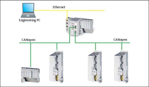
3 Controller-based Automation: Central motion control
The Lenze automation system "Controller-based Automation" serves to create complex automation solutions with central motion control. Here, the Controller is the control centre of the system.
System structure of the Controller-based Automation: "All from one single source"
[3-1] Example: CANopen with the 3231 C Lenze Controller (I/O system 1000 and Servo Drive 9400 as slaves)
Lenze · Controller-based Automation · CANopen® Communication Manual · DMS 6.3 EN · 04/2014 · TD17 |
12 |
3 Controller-based Automation: Central motion control
_ _ _ _ _ _ _ _ _ _ _ _ _ _ _ _ _ _ _ _ _ _ _ _ _ _ _ _ _ _ _ _ _ _ _ _ _ _ _ _ _ _ _ _ _ _ _ _ _ _ _ _ _ _ _ _ _ _ _ _ _ _ _ _
Lenze provides especially coordinated system components:
•Engineering software
The Lenze Engineering tools ( 19) on your Engineering PC (Windows operating system ) serve to parameterise, configure and diagnose the system. The Engineering PC communicates with the Controller via Ethernet.
•Controller
The Lenze Controller is available as Panel Controller with integrated touch display and as Cabinet Controller in control cabinet design.
Cabinet Controllers provide a direct coupling of the I/O system 100 via the integrated backplane bus.
The runtime software of the Lenze Controllers provides the control and/or visualisation of motion sequences. The following software versions are available:
•"Logic": Sequence control in the Controller, motion control in the inverter
•"Motion": Sequence control and motion control in the Controller, inverter as actuating drive
•"Visu": Optional visualisation of the automation system, can be used separately or in addition to "Logic" or "Motion"
An external monitor panel/display can be connected to the Cabinet Controller 3231 C/ 3241 C.
•Without software: Controller as single component with operating system only
•Bus systems
EtherCAT is a standard "on board" bus system of the Controller-based Automation. EtherCAT enables the control of all nodes (Motion/Logic) on one common fieldbus.
Optionally, CANopen, PROFIBUS and PROFINET can be used as extended topologies.
The Controllers c300/p300 have a CANopen interface "on board" as well (in addition to EtherCAT).
•Inverter (e.g. Servo Inverter i700)
"Logic & Motion" runtime software
The "Controller-based Automation" system allows for the central control of devices for Logic and Motion applications. The runtime software runs on the Controller.
In case of Logic applications, the sequence control is carried out in the Controller and the motion control is carried out in the inverter.
In case of Motion applications , the sequence control and motion control are carried out in the Controller. The inverter is used as actuating drive.
•Motion applications make special demands on the cycle time and real-time capability of the bus system between the Controller and the subordinate fieldbus nodes.
•this is for instance the case if the field devices, for example, are to move in a synchronised way or if position setpoints are to be transmitted.
13 |
Lenze · Controller-based Automation · CANopen® Communication Manual · DMS 6.3 EN · 04/2014 · TD17 |

3 Controller-based Automation: Central motion control
_ _ _ _ _ _ _ _ _ _ _ _ _ _ _ _ _ _ _ _ _ _ _ _ _ _ _ _ _ _ _ _ _ _ _ _ _ _ _ _ _ _ _ _ _ _ _ _ _ _ _ _ _ _ _ _ _ _ _ _ _ _ _ _
Fieldbus communication
The Lenze Controllers have different interfaces for fieldbus communication:
Area |
|
Cabinet Controller |
|
Panel Controller |
||
|
c300 |
3221 C |
3231 C |
3241 C |
p300 |
p500 |
Interfaces (on board) |
|
|
|
|
|
|
Ethernet |
1 |
|
2 |
|
1 |
2 |
EtherCAT |
1 1) |
|
1 |
|
1 1) |
1 |
CANopen |
1 2) |
|
- |
|
1 2) |
- |
Optional interfaces (communication cards) |
|
|
|
|
||
CANopen |
- |
|
|
|
- |
|
MC-CAN2 |
|
|
|
|
|
|
PROFIBUS master |
- |
|
|
|
- |
|
MC-PBM |
|
|
|
|
|
|
PROFIBUS slave |
- |
|
|
|
- |
|
MC-PBS |
|
|
|
|
|
|
PROFINET device |
- |
|
|
|
- |
|
MC-PND |
|
|
|
|
|
|
|
|
|
|
|
|
|
1)In preparation
2)Only the CAN master functionality is supported.
The Ethernet interface serves to connect the Engineering PC or to create line topologies (no integrated switch for Controller c300/p300).
More information on the bus systems and configuration can be found in the communication manuals:
•Controller-based Automation EtherCAT®
•Controller-based Automation CANopen®
•Controller-based Automation PROFIBUS®
•Controller-based Automation PROFINET®
Lenze · Controller-based Automation · CANopen® Communication Manual · DMS 6.3 EN · 04/2014 · TD17 |
14 |
4 System bus (CAN) / CANopen
_ _ _ _ _ _ _ _ _ _ _ _ _ _ _ _ _ _ _ _ _ _ _ _ _ _ _ _ _ _ _ _ _ _ _ _ _ _ _ _ _ _ _ _ _ _ _ _ _ _ _ _ _ _ _ _ _ _ _ _ _ _ _ _
4 |
System bus (CAN) / CANopen |
The control technology based on CANopen allows for the integration of all Lenze device series provided with the Lenze system bus (CAN on board).
In order to extend the existing limits of the CAN bus, several CAN lines synchronised with each other can be used. The number of CAN lines available depends on the equipment of the Lenze Controller in each case.
The maximum possible number of nodes on a CAN line depends on the baud rate and the cycle time set.
Example: In the case of a cycle time of 1 ms and a baud rate of 1 Mbps, three nodes with a setpoint PDO and an actual value PDO, respectively, can be actuated on the CAN bus.
Tip!
Detailed information on CAN/CANopen can be found on the website of the CAN User Organization CiA (CAN in Automation):
www.can-cia.org
15 |
Lenze · Controller-based Automation · CANopen® Communication Manual · DMS 6.3 EN · 04/2014 · TD17 |
4 System bus (CAN) / CANopen
4.1CANopen (Logic) / CANopen (Motion)
_ _ _ _ _ _ _ _ _ _ _ _ _ _ _ _ _ _ _ _ _ _ _ _ _ _ _ _ _ _ _ _ _ _ _ _ _ _ _ _ _ _ _ _ _ _ _ _ _ _ _ _ _ _ _ _ _ _ _ _ _ _ _ _
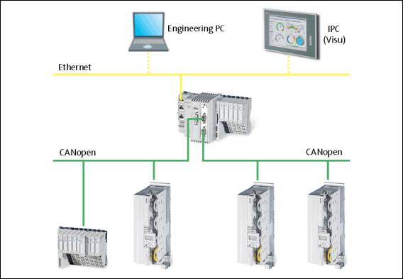
4.1CANopen (Logic) / CANopen (Motion)
[4-1] Example: CANopen (Logic/Motion) with the 3231 C controller (I/O system 1000 and Servo Drive 9400 as slaves)
Due to the requirements regarding the real time behaviour of the fieldbus system and due to its limited transfer capacity, it is useful to operate Logic and Motion devices on separate CAN phases if CANopen is used – on a logic bus and a motion bus.
The Lenze Controllers ...
•with the Communication card MC-CAN2 ( 18) have two CAN interfaces for CANopen (Logic) and CANopen (Motion);
•can also be used as CAN slaves.
Depending on the required number of Motion nodes and bus cycle time, up to 2 Motion bus lines can be created.
Tip!
A sample project for operation of a 3200 C controller as CAN slave can be found in the "Download" area at www.Lenze.com:
"Application Knowledge Base": All articles Application Ideas Pool Controller 3200 C
Lenze · Controller-based Automation · CANopen® Communication Manual · DMS 6.3 EN · 04/2014 · TD17 |
16 |
4 System bus (CAN) / CANopen
4.2Field devices
_ _ _ _ _ _ _ _ _ _ _ _ _ _ _ _ _ _ _ _ _ _ _ _ _ _ _ _ _ _ _ _ _ _ _ _ _ _ _ _ _ _ _ _ _ _ _ _ _ _ _ _ _ _ _ _ _ _ _ _ _ _ _ _
4.2Field devices
The Lenze automation system supports the following Logic/Motion components:
Field devices |
|
System bus (CAN/CANopen) |
|
|
|
Logic |
Motion |
Controller |
Controller 32xx C |
|
|
|
|
|
|
|
Controller c300 |
|
|
|
|
|
|
|
Controller p300 |
|
|
|
|
|
|
|
Controller p500 |
|
|
Servo Drives 9400 |
HighLine 1) |
|
|
|
|
|
|
|
HighLine with CiA402 |
|
|
|
|
|
|
|
PLC |
|
|
|
|
|
|
|
Regenerative power supply |
|
|
|
module |
|
|
Inverter Drives 8400 |
BaseLine |
|
|
|
|
|
|
|
StateLine |
|
|
|
|
|
|
|
HighLine |
|
|
|
|
|
|
|
TopLine |
|
|
I/O-System 1000 |
EPM-Sxxx |
|
|
|
|
|
|
1) with technology application (TA)
17 |
Lenze · Controller-based Automation · CANopen® Communication Manual · DMS 6.3 EN · 04/2014 · TD17 |

4 System bus (CAN) / CANopen
4.3CANopen hardware for Lenze Controllers
_ _ _ _ _ _ _ _ _ _ _ _ _ _ _ _ _ _ _ _ _ _ _ _ _ _ _ _ _ _ _ _ _ _ _ _ _ _ _ _ _ _ _ _ _ _ _ _ _ _ _ _ _ _ _ _ _ _ _ _ _ _ _ _
4.3CANopen hardware for Lenze Controllers
Communication card MC-CAN2
The MC-CAN2 communication card serves to connect a Lenze Controller to the CAN bus system. The card provides two independent bus lines.
A Front panel
B Printed circuit board
C Coding
D Connection of Lenze Controller
E CAN connection
MC-CAN2-001
[4-2] Communication card MC-CAN2
Technical data of the MC-CAN2 communication card ( 21)
Use
The MC-CAN2 communication card is installed in the corresponding slot of the Lenze Controller.
Example: Lenze Controller 3231 C with MC-CAN2 communication card
MC-CAN2 |
Communication card MC-CAN2 |
|
|
CAN1 |
Connections for the 2 bus lines |
CAN2 |
• CAN1: CANopen (Logic and/or Motion) |
|
• CAN2: CANopen (Logic and/or Motion) |
|
|
Lenze · Controller-based Automation · CANopen® Communication Manual · DMS 6.3 EN · 04/2014 · TD17 |
18 |
4 System bus (CAN) / CANopen
4.4Lenze Engineering tools
_ _ _ _ _ _ _ _ _ _ _ _ _ _ _ _ _ _ _ _ _ _ _ _ _ _ _ _ _ _ _ _ _ _ _ _ _ _ _ _ _ _ _ _ _ _ _ _ _ _ _ _ _ _ _ _ _ _ _ _ _ _ _ _
4.4Lenze Engineering tools
The Lenze Engineering tools enable the configuration and operation of controller-based Lenze automation systems according to individual requirements.
Use the corresponding Engineering tool applicable to the field device.
 »EASY Navigator«
The »EASY Navigator« provides an overview of the Lenze Engineering software installed on the Engineering PC.
The Lenze Engineering software consists of the Engineering tools optimised for the respective application case.
The »EASY Navigator« ...
•simplifies orientation for selecting the suitable Engineering tool;
•allows for the simple start of the required Engineering tool (depending on the application):
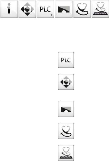
What would you like to do? |
Button |
Engineering tool |
Programming |
|
»PLC Designer« |
• Parameterise the Lenze Controller |
|
|
• Parameterise the i700 servo inverter |
|
|
• Parameterise the I/O system 1000 |
|
|
|
|
|
Configuring the inverter |
|
»Engineer« |
• Projecting the automation/drive system |
|
|
• Parameterisation/configuration |
|
|
• Inverter Drives 8400, 8400 motec/protec |
|
|
• Servo Drives 9400 |
|
|
• I/O-System 1000 |
|
|
Visualising |
|
»VisiWinNET« |
• Visualising the automation system |
|
|
• Creating the user interface |
|
|
|
|
|
Online diagnostics |
|
»EASY Starter« |
Easy online diagnostics of Lenze Controllers and |
|
|
other Lenze field devices |
|
|
|
|
|
Online parameterisation |
|
»EASY Starter« |
• Online parameterisation and commissioning |
|
|
• Direct online parameterisation when the online |
|
|
connection to the Lenze devices is active. |
|
|
|
|
|
Further Engineering tools that are not called via the »EASY Navigator« are:
•»WebConfig« (web-based parameterisation, configuration, and online diagnostics)
•»Backup & Restore« (data backup, data recovery).
19 |
Lenze · Controller-based Automation · CANopen® Communication Manual · DMS 6.3 EN · 04/2014 · TD17 |
5 Technical data
5.1General data
_ _ _ _ _ _ _ _ _ _ _ _ _ _ _ _ _ _ _ _ _ _ _ _ _ _ _ _ _ _ _ _ _ _ _ _ _ _ _ _ _ _ _ _ _ _ _ _ _ _ _ _ _ _ _ _ _ _ _ _ _ _ _ _
5 |
Technical data |
|
5.1 |
General data |
|
|
|
|
|
Area |
Values |
|
Communication profile |
CANopen (DS301, V4.02) |
|
Standards |
CAN, ISO 11898 / EN 50325-4 |
|
Network topology |
Line, terminated at both ends with 120 |
|
|
(e.g. terminated with Sub-D plug of type EWZ0046) |
|
Max. number of nodes |
127 |
|
Adjustable node addresses |
1 ... 127 |
|
|
(adjustable for Lenze devices via DIP switches) |
|
Baud rates [kbps] |
• 10 |
|
|
• 20 |
|
|
• 50 |
|
|
• 125 |
|
|
• 250 |
|
|
• 500 |
|
|
• 1000 |
|
Parameter data |
Max. 10 client and server SDO channels with 1 ... 8 bytes |
|
Cycle time - Motion/CNC task |
1 ... 16 ms |
|
Number of drives/ms on the Motion |
Max. 3 drives/ms |
|
bus |
|
|
Signal propagation delay drive |
4 cycles |
|
controller drive |
|
|
Cross communication |
Only possible with CANopen (Logic) |
|
|
In the case of CANopen (Motion), communication is executed centrally via |
|
|
the Lenze Controller. |
|
Number of DI + DO (bits/ms) |
384 (max. 6 PDOs/ms on the Logic bus) |
|
Cycle synchronisation with locked |
+/-10 μs |
|
PLL (Jitter) |
|
|
|
|
Lenze · Controller-based Automation · CANopen® Communication Manual · DMS 6.3 EN · 04/2014 · TD17 |
20 |
5 Technical data
5.2Technical data of the MC-CAN2 communication card
_ _ _ _ _ _ _ _ _ _ _ _ _ _ _ _ _ _ _ _ _ _ _ _ _ _ _ _ _ _ _ _ _ _ _ _ _ _ _ _ _ _ _ _ _ _ _ _ _ _ _ _ _ _ _ _ _ _ _ _ _ _ _ _
5.2Technical data of the MC-CAN2 communication card
Area |
Values |
Type within the network |
Master or slave |
Max. number of nodes |
63 |
Max. baud rate |
1000 kbps |
Bus length |
See chapter "Bus cable length" ( 22) |
Connection |
SUB-D, 9-pole plug |
|
|
Connection of CAN bus (SUB-D, 9-pole plug)
View |
Pin |
Assignment |
Description |
|
1 |
free |
- |
|
|
|
|
|
2 |
LO |
CAN-LOW |
|
|
|
|
|
3 |
CG |
CAN-Ground |
|
|
|
|
|
4 |
free |
- |
|
|
|
|
|
5 |
free |
- |
|
|
|
|
|
6 |
CG |
CAN-Ground |
|
|
|
|
|
7 |
HI |
CAN-HIGH |
|
|
|
|
|
8 |
free |
- |
|
|
|
|
|
9 |
free |
- |
|
|
|
|
5.3Bus cable specification
We recommend to use CAN cables according to ISO 11898-2:
CAN cables according to ISO 11898-2
Cable type |
Paired cable with shield |
|
|
Impedance |
120 (95 ... 140 ) |
Cable resistance/cross-section
Cable length 300 m: 70 m /m / 0.25... 0.34 mm2 (AWG22)
Cable length 301 ... 1000 m: 40 m /m / 0.5 mm2 (AWG20)
Signal propagation delay |
5 ns/m |
21 |
Lenze · Controller-based Automation · CANopen® Communication Manual · DMS 6.3 EN · 04/2014 · TD17 |

5 Technical data
5.4Bus cable length
_ _ _ _ _ _ _ _ _ _ _ _ _ _ _ _ _ _ _ _ _ _ _ _ _ _ _ _ _ _ _ _ _ _ _ _ _ _ _ _ _ _ _ _ _ _ _ _ _ _ _ _ _ _ _ _ _ _ _ _ _ _ _ _
5.4Bus cable length
Note!
•It is absolutely necessary to comply with the permissible cable lengths.
•Observe the reduction of the total cable length due to the signal delay of the repeater.Use of repeaters ( 23)
•If the total cable lengths of the nodes are different at the same baud rate, the smaller value must be used to determine the max. cable length.
5.4.1Total cable length
The total cable length is also specified by the baud rate.
Baud rate [kbps] |
Max. bus length [m] |
|
|
|
Servo Drives |
Inverter Drives |
I/O-System 1000 |
|
9400 |
8400 |
(EPM-Sxxx) |
|
|
|
CANopen bus coupler |
10 |
8000 |
- |
5000 |
20 |
4000 |
- |
2500 |
50 |
1500 |
1500 |
1000 |
125 |
600 |
600 |
500 |
250 |
275 |
275 |
250 |
500 |
110 |
110 |
80 |
1000 |
13 |
13 |
25 |
|
|
|
|
5.4.2Segment cable length
Repeaters divide the total cable length into segments. The segment cable length is defined by the cable cross-section and the number of nodes per segment. Without a repeater, the segment cable length corresponds to the total cable length.
Max. number of |
Cable cross-section |
|
|
|
nodes per segment |
0.25 mm2 |
0.50 mm2 |
0.75 mm2 |
1.00 mm2 |
|
||||
2 |
240 m |
430 m |
650 m |
940 m |
5 |
230 m |
420 m |
640 m |
920 m |
10 |
230 m |
410 m |
620 m |
900 m |
20 |
210 m |
390 m |
580 m |
850 m |
32 |
200 m |
360 m |
550 m |
800 m |
63 |
170 m |
310 m |
470 m |
690 m |
100 |
150 m |
270 m |
410 m |
600 m |
|
|
|
|
|
Lenze · Controller-based Automation · CANopen® Communication Manual · DMS 6.3 EN · 04/2014 · TD17 |
22 |
5 Technical data
5.4Bus cable length
_ _ _ _ _ _ _ _ _ _ _ _ _ _ _ _ _ _ _ _ _ _ _ _ _ _ _ _ _ _ _ _ _ _ _ _ _ _ _ _ _ _ _ _ _ _ _ _ _ _ _ _ _ _ _ _ _ _ _ _ _ _ _ _
5.4.3Use of repeaters
Compare the values from the tables Total cable length ( 22) and Segment cable length ( 22).
If the detected segment cable length is smaller than the total cable length to be achieved, repeaters must be used.
Example: Detecting cable lengths / number of repeaters
Given: |
|
Cable cross-section |
0.5 mm2, according to Bus cable specification ( 21) |
Number of nodes |
127 |
Repeater |
Lenze repeater, type 2176 (cable reduction: 30 m) |
|
|
At the maximum number of nodes (127), the following cable lengths/number of repeaters from the specifications have to be observed:
Baud rate [kbps] |
10 |
20 |
50 |
125 |
250 |
500 |
800 |
1000 |
Max. cable length [m] |
8000 |
3900 |
1500 |
630 |
290 |
110 |
40 |
17 |
Segment cable length [m] |
270 |
270 |
270 |
270 |
270 |
110 |
40 |
17 |
Number of repeaters |
33 |
16 |
6 |
2 |
1 |
- |
- |
- |
|
|
|
|
|
|
|
|
|
23 |
Lenze · Controller-based Automation · CANopen® Communication Manual · DMS 6.3 EN · 04/2014 · TD17 |
5 Technical data
5.4Bus cable length
_ _ _ _ _ _ _ _ _ _ _ _ _ _ _ _ _ _ _ _ _ _ _ _ _ _ _ _ _ _ _ _ _ _ _ _ _ _ _ _ _ _ _ _ _ _ _ _ _ _ _ _ _ _ _ _ _ _ _ _ _ _ _ _
Example: Check use of repeater
Given:
Baud rate |
125 kbps |
|
|
|
|
|
|
|
|
Cable cross-section |
0.5 mm2 |
|
|
|
Number of nodes |
28 |
|
|
|
|
|
|
|
|
Cable length |
450 m |
|
|
|
|
|
|
|
|
Test step |
Cable length |
See table ... |
|
|
1 |
Total cable length at 125 kbps: |
630 m |
Total cable length ( 22) |
|
2 |
Segment cable length for 28 nodes and a cable cross- |
360 m |
Segment cable length |
( 22) |
|
section of 0.5 mm2: |
|
|
|
3 |
Comparison: The detected segment cable length is |
|
|
|
|
smaller than the total cable length of 450 m to be |
|
|
|
|
achieved. |
|
|
|
|
|
|
|
|
Conclusion:
• It is not possible to use a cable length of 450 m without using a repeater.
•After 360 m (test step 2) a repeater has to be used. Result:
•The Lenze repeater, type 2176 (cable reduction: 30 m), is used
•Calculation of the maximum cable length:
•First segment: 360 m
•Second segment: 360 m (see table Segment cable length ( 22)) minus 30 m (cable reduction for a repeater)
•Max. achievable cable length with a repeater: 690 m
•The selected cable length can be implemented.
Lenze · Controller-based Automation · CANopen® Communication Manual · DMS 6.3 EN · 04/2014 · TD17 |
24 |
6 Planning the CANopen network
_ _ _ _ _ _ _ _ _ _ _ _ _ _ _ _ _ _ _ _ _ _ _ _ _ _ _ _ _ _ _ _ _ _ _ _ _ _ _ _ _ _ _ _ _ _ _ _ _ _ _ _ _ _ _ _ _ _ _ _ _ _ _ _
6 |
Planning the CANopen network |
Create an overview screen of the planned CANopen network with all field devices to be implemented. Start with the Lenze Controller and arrange the other field devices below it (see Example of an overview screen ( 27)).
Provide the following data for each device:
Type |
Type designation of the field device |
|
|
Used CAN interface of the device |
• The functionality of the two available CAN interfaces is identical. Both |
|
Logic and Motion devices can be connected. The combination of Logic and |
|
Motion on an interface is possible as well. |
|
• If possible, the Logic and Motion devices should be installed on different |
|
CAN lines: |
|
• The requirements of the Motion devices regarding the synchronicity of |
|
the bus are higher. |
|
• Shorter cycle times are needed. |
|
• The data volume to be transferred is larger. |
|
CANopen (Logic) / CANopen (Motion) ( 16) |
Unambiguous CAN node address |
• If system bus (CAN) devices are used, max. 63 nodes/node addresses are |
|
possible. |
|
• With CANopen-compliant devices, up to 127 nodes/node addresses are |
|
possible. |
|
Note: Do not use the node address 1, in order to avoid unintentional |
|
mistakes and conflicts with a device containing the factory adjustment. |
|
|
Baud rate |
• The baud rate applies to all nodes of the CANopen network. |
|
• 50, 125, 250 and 500 kbps are supported by all device types of the system. |
|
• Observe the connection between bus cable length and baud rate. Bus |
|
cable length ( 22) |
Master task of the device |
• An NMT master sets itself and then the NMT slaves to the "Operational" |
(NMT master/Sync master) |
state. In this state, process data can be communicated. Generally, there |
|
can be an optional number of NMT masters on one CANopen bus. |
|
• A Sync master cyclically sends a sync telegram providing for an exactly |
|
simultaneous processing of process data and/or a simultaneous task |
|
start in all sync receivers. |
|
• Via CAN synchronisation, the Lenze Controller can influence the exact |
|
time of the following events in the field device: |
|
• Acceptance and transmission of sync-controlled PDOs |
|
• Starting time of the task of the application (only possible in 9400) |
|
• You only need to use CAN synchronisation on the Logic bus if an exact |
|
simultaneity in the range of milliseconds is of importance. A mere |
|
operating periphery (operator button, control lamps, etc.) does not |
|
require CAN synchronisation. |
|
|
CAN objects and COB-IDs |
• Plan your COB-IDs according to the CANopen DS301 communication |
|
profile. This convention is optimised for the communication with a |
|
central master device. COB-IDs acc. to DS301 ( 26) |
|
• Up to 4 PDOs per device can be identified with this scheme. If you require |
|
more, e.g. for a modular I/O system with more than 8 modules, you can |
|
add them later. |
|
• You can easily assign the node during the bus diagnostics by means of the |
|
COB-IDs. |
|
• COB-ID = basic identifier + node address |
|
|
25 |
Lenze · Controller-based Automation · CANopen® Communication Manual · DMS 6.3 EN · 04/2014 · TD17 |

6 Planning the CANopen network
6.1COB-IDs acc. to DS301
_ _ _ _ _ _ _ _ _ _ _ _ _ _ _ _ _ _ _ _ _ _ _ _ _ _ _ _ _ _ _ _ _ _ _ _ _ _ _ _ _ _ _ _ _ _ _ _ _ _ _ _ _ _ _ _ _ _ _ _ _ _ _ _
Please observe ...
the device-specific information on the CAN configuration in the documentation for the field devices to be implemented.
6.1COB-IDs acc. to DS301
Object |
|
Direction |
Basic identifier |
||
|
|
from the drive |
to the drive |
Dec |
hex |
NMT |
|
|
|
0 |
0x000 |
Sync |
|
|
|
128 |
0x080 |
Time Stamp |
|
|
|
256 |
0x100 |
Emergency |
|
|
|
128 |
0x080 |
PDO1 |
TPDO1 |
|
|
384 |
0x180 |
(Process data channel 1) |
|
|
|
|
|
RPDO1 |
|
|
512 |
0x200 |
|
|
|
||||
PDO2 |
TPDO2 |
|
|
640 |
0x280 |
(Process data channel 2) |
|
|
|
|
|
RPDO2 |
|
|
768 |
0x300 |
|
|
|
||||
PDO3 |
TPDO3 |
|
|
896 |
0x380 |
(Process data channel 3) |
|
|
|
|
|
RPDO3 |
|
|
1024 |
0x400 |
|
|
|
||||
PDO4 |
TPDO4 |
|
|
1152 |
0x480 |
(Process data channel 4) |
|
|
|
|
|
RPDO4 |
|
|
1280 |
0x500 |
|
|
|
||||
SDO |
|
|
|
1408 |
0x580 |
(Parameter data channel 1) |
|
|
|
|
|
|
|
|
1536 |
0x600 |
|
|
|
|
|||
NMT Error Control |
|
|
|
1792 |
0x700 |
|
|
|
|
|
|
Note!
In Lenze system bus (CAN) devices, two SDO channels are permanently active, in CANopen devices, only one by default.
When using CANopen devices, activate a second SDO channel for access of the »Engineer«. Otherwise communication with the device will be interfered if you go online with the »Engineer« while the Lenze Controller has access as well.
The COB-IDs for your CANopen network can be calculated according to the following formula:
COB-ID = basic identifier + node address
Basic identifier - 9400 Servo Drives ( 29)Basic identifier - 8400 Inverter Drives ( 30)
Basic identifier - I/O system 1000 (EPM-Sxxx) ( 31)
Lenze · Controller-based Automation · CANopen® Communication Manual · DMS 6.3 EN · 04/2014 · TD17 |
26 |
6 Planning the CANopen network
6.2Example of an overview screen
_ _ _ _ _ _ _ _ _ _ _ _ _ _ _ _ _ _ _ _ _ _ _ _ _ _ _ _ _ _ _ _ _ _ _ _ _ _ _ _ _ _ _ _ _ _ _ _ _ _ _ _ _ _ _ _ _ _ _ _ _ _ _ _
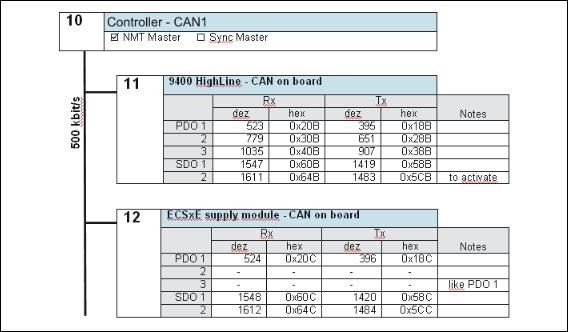
6.2Example of an overview screen
The illustration shows you an example of an overview screen for planning a CANopen network:
[6-1] Example of an overview screen for designing a CANopen network
27 |
Lenze · Controller-based Automation · CANopen® Communication Manual · DMS 6.3 EN · 04/2014 · TD17 |
6 Planning the CANopen network
6.3Device specifications of the field devices
_ _ _ _ _ _ _ _ _ _ _ _ _ _ _ _ _ _ _ _ _ _ _ _ _ _ _ _ _ _ _ _ _ _ _ _ _ _ _ _ _ _ _ _ _ _ _ _ _ _ _ _ _ _ _ _ _ _ _ _ _ _ _ _
6.3Device specifications of the field devices
When planning your CANopen network, consider the device specifications of the implemented field devices.
Overview of the device specifications for operation with a Lenze Controller
|
Servo Drives 9400 |
Inverter Drives 8400 |
I/O-System 1000 |
|
|
|
(EPM-Sxxx) |
CAN interface |
• on board |
on board |
on board |
|
• CANopen module |
|
|
Available PDOs |
4 Transmit (Tx) + |
3 Transmit (Tx) + |
10 Transmit (Tx) + |
|
4 Receive (Rx) |
3 Receive (Rx) |
10 Receive (Rx) |
Can unused PDOs be |
yes |
yes |
yes |
deactivated? |
|
|
|
Can PDO COB-IDs be freely |
yes |
yes |
yes |
selected? |
|
|
|
Can PDO transfer characteristics |
yes |
yes |
yes |
be adjusted? |
|
|
|
Available SDO channels |
1 ex works (fixed), |
2 ex works (fixed) |
1 ex works (fixed), |
|
9 further can be activated |
|
1 more can be activated |
Can SDO COB-IDs be freely |
only for channel 2 ... 10 |
no |
no |
selected? |
|
|
|
|
|
|
|
Lenze · Controller-based Automation · CANopen® Communication Manual · DMS 6.3 EN · 04/2014 · TD17 |
28 |

6 Planning the CANopen network
6.3Device specifications of the field devices
_ _ _ _ _ _ _ _ _ _ _ _ _ _ _ _ _ _ _ _ _ _ _ _ _ _ _ _ _ _ _ _ _ _ _ _ _ _ _ _ _ _ _ _ _ _ _ _ _ _ _ _ _ _ _ _ _ _ _ _ _ _ _ _
6.3.1Special features of the 9400 Servo Drives
•The parameter data channel 1 is always active.
•The optional parameter data channels 2 ... 10 can be activated via the subcodes of the codes Cxx372 and Cxx373.
SDO identifier |
Code |
CANopen SDO server Rx identifier |
C00372: CAN on board |
|
|
|
C13372: Module in slot 1 |
|
|
|
C14372: Module in slot 2 |
CANopen SDO server Tx identifier |
C00373: CAN on board |
|
|
|
C13373: Module in slot 1 |
|
|
|
C14373: Module in slot 2 |
|
|
•If bit 31 is set (0x8nnnnnnn), the corresponding SDO server is deactivated.
•In order to change the COB-ID of a currently active parameter data channel, you have to first deactivate it and then activate it with a changed COB-ID. Both processes must be rendered effective by a "Reset Node" command via C00002.
Basic identifier - 9400 Servo Drives
The default setting of the basic identifier is as follows:
Object |
|
Direction |
Basic identifier |
||
|
|
from the drive |
to the drive |
Dec |
hex |
NMT |
|
|
|
0 |
0x000 |
Sync 1) |
|
|
|
128 |
0x080 |
Emergency |
|
|
|
128 |
0x080 |
PDO1 |
TPDO1 |
|
|
384 |
0x180 |
(Process data channel 1) |
|
|
|
|
|
RPDO1 |
|
|
512 |
0x200 |
|
|
|
||||
PDO2 |
TPDO2 |
|
|
640 |
0x280 |
(Process data channel 2) |
|
|
|
|
|
RPDO2 |
|
|
768 |
0x300 |
|
|
|
||||
PDO3 |
TPDO3 |
|
|
896 |
0x380 |
(Process data channel 3) |
|
|
|
|
|
RPDO3 |
|
|
1024 |
0x400 |
|
|
|
||||
PDO4 |
TPDO4 |
|
|
1152 |
0x480 |
(Process data channel 4) |
|
|
|
|
|
RPDO4 |
|
|
1280 |
0x500 |
|
|
|
||||
SDO1 |
TSDO1 |
|
|
1408 |
0x580 |
(Parameter data channel 1) |
|
|
|
|
|
RSDO1 |
|
|
1536 |
0x600 |
|
|
|
||||
SDO2 ... 10 |
TSDOx |
|
|
1472 |
0x5C0 |
(Parameter data channel 2 ... 10) |
|
|
|
|
|
RSDOx |
|
|
1600 |
0x640 |
|
|
|
||||
Node guarding, heartbeat |
|
|
|
1792 |
0x700 |
|
|
|
|
|
|
1) When creating the sync transmit/receive identifier manually, observe the use of the emergency telegram because of the same COB-ID.
29 |
Lenze · Controller-based Automation · CANopen® Communication Manual · DMS 6.3 EN · 04/2014 · TD17 |

6 Planning the CANopen network
6.3Device specifications of the field devices
_ _ _ _ _ _ _ _ _ _ _ _ _ _ _ _ _ _ _ _ _ _ _ _ _ _ _ _ _ _ _ _ _ _ _ _ _ _ _ _ _ _ _ _ _ _ _ _ _ _ _ _ _ _ _ _ _ _ _ _ _ _ _ _
6.3.2Special features of the 8400 Inverter Drives
Basic identifier - 8400 Inverter Drives
The default setting of the basic identifier is as follows:
Object |
|
Direction |
Basic identifier |
||
|
|
from the drive |
to the drive |
Dec |
hex |
NMT |
|
|
|
0 |
0x000 |
Sync 1) |
|
|
|
128 |
0x080 |
Emergency |
|
|
|
128 |
0x080 |
PDO1 |
TPDO1 |
|
|
384 |
0x180 |
(Process data channel 1) |
|
|
|
|
|
RPDO1 |
|
|
512 |
0x200 |
|
|
|
||||
PDO2 |
TPDO2 |
|
|
640 |
0x280 |
(Process data channel 2) |
|
|
|
|
|
RPDO2 |
|
|
641 |
0x281 |
|
|
|
||||
PDO3 |
TPDO3 |
|
|
768 |
0x300 |
(Process data channel 3) |
|
|
|
|
|
RPDO3 |
|
|
769 |
0x301 |
|
|
|
||||
SDO1 |
TSDO1 |
|
|
1408 |
0x580 |
(Parameter data channel 1) |
|
|
|
|
|
RSDO1 |
|
|
1536 |
0x600 |
|
|
|
||||
SDO2 |
TSDO2 |
|
|
1472 |
0x5C0 |
(Parameter data channel 2) |
|
|
|
|
|
RSDO2 |
|
|
1600 |
0x640 |
|
|
|
||||
Heartbeat |
|
|
|
1792 |
0x700 |
Boot-up 2) |
|
|
|
1792 |
0x700 |
|
|
|
|
|
|
1)When creating the sync transmit/receive identifier manually, observe the use of the emergency telegram because of the same COB-ID.
2)When the boot-up identifier is set manually, observe the use of heartbeat because of the same COB-ID.
Lenze · Controller-based Automation · CANopen® Communication Manual · DMS 6.3 EN · 04/2014 · TD17 |
30 |
Loading...