


 Loading...
KHBCANPCBAUTO 13383676
Ä.GEmä
L-force Controls
Communication manual
PC-based Automation
CANopen control technology
Commissioning & Configuration
L
2 |
L |
DMS 4.2 EN 07/2011 TD17

Control technology | CANopen communication manual
Contents
1 |
About this documentation . . . . . . . . . . . . . . . . . . . . . . . . . . . . . . . . . . . . . . . . . . . . . . . . . . . . . . . . . |
6 |
||
|
1.1 |
Document history . . . . . . . . . . . . . . . . . . . . . . . . . . . . . . . . . . . . . . . . . . . . . . . . . . . . . . . . . . . . . . . |
8 |
|
|
1.2 |
Conventions used . . . . . . . . . . . . . . . . . . . . . . . . . . . . . . . . . . . . . . . . . . . . . . . . . . . . . . . . . . . . . . . |
9 |
|
|
1.3 |
Terminology used . . . . . . . . . . . . . . . . . . . . . . . . . . . . . . . . . . . . . . . . . . . . . . . . . . . . . . . . . . . . . . . |
10 |
|
|
1.4 |
Notes used. . . . . . . . . . . . . . . . . . . . . . . . . . . . . . . . . . . . . . . . . . . . . . . . . . . . . . . . . . . . . . . . . . . . . . |
11 |
|
2 |
Safety instructions . . . . . . . . . . . . . . . . . . . . . . . . . . . . . . . . . . . . . . . . . . . . . . . . . . . . . . . . . . . . . . . . |
12 |
||
3 |
The "PC-based Automation" system . . . . . . . . . . . . . . . . . . . . . . . . . . . . . . . . . . . . . . . . . . . . . . . . . |
13 |
||
4 |
System bus (CAN) / CANopen. . . . . . . . . . . . . . . . . . . . . . . . . . . . . . . . . . . . . . . . . . . . . . . . . . . . . . . |
15 |
||
|
4.1 |
CANopen (Logic) / CANopen (Motion) . . . . . . . . . . . . . . . . . . . . . . . . . . . . . . . . . . . . . . . . . . . . |
15 |
|
|
|
4.1.1 Combination with other bus systems . . . . . . . . . . . . . . . . . . . . . . . . . . . . . . . . . . . . . |
16 |
|
|
|
4.1.2 |
Field devices. . . . . . . . . . . . . . . . . . . . . . . . . . . . . . . . . . . . . . . . . . . . . . . . . . . . . . . . . . . . . |
17 |
|
4.2 |
CANopen Hardware for your Industrial PC . . . . . . . . . . . . . . . . . . . . . . . . . . . . . . . . . . . . . . . . |
18 |
|
5 |
Technical data . . . . . . . . . . . . . . . . . . . . . . . . . . . . . . . . . . . . . . . . . . . . . . . . . . . . . . . . . . . . . . . . . . . . |
20 |
||
|
5.1 |
General data . . . . . . . . . . . . . . . . . . . . . . . . . . . . . . . . . . . . . . . . . . . . . . . . . . . . . . . . . . . . . . . . . . . . |
20 |
|
|
5.2 |
Technical data of the MC-CAN2 communication card . . . . . . . . . . . . . . . . . . . . . . . . . . . . . |
21 |
|
|
5.3 |
Bus cable specification . . . . . . . . . . . . . . . . . . . . . . . . . . . . . . . . . . . . . . . . . . . . . . . . . . . . . . . . . . |
21 |
|
|
5.4 |
Bus cable length . . . . . . . . . . . . . . . . . . . . . . . . . . . . . . . . . . . . . . . . . . . . . . . . . . . . . . . . . . . . . . . . |
22 |
|
|
|
5.4.1 |
Total cable length . . . . . . . . . . . . . . . . . . . . . . . . . . . . . . . . . . . . . . . . . . . . . . . . . . . . . . . |
22 |
|
|
5.4.2 |
Segment cable length. . . . . . . . . . . . . . . . . . . . . . . . . . . . . . . . . . . . . . . . . . . . . . . . . . . . |
23 |
|
|
5.4.3 Check use of repeater . . . . . . . . . . . . . . . . . . . . . . . . . . . . . . . . . . . . . . . . . . . . . . . . . . . . |
24 |
|
6 |
Planning the CANopen network . . . . . . . . . . . . . . . . . . . . . . . . . . . . . . . . . . . . . . . . . . . . . . . . . . . . |
25 |
||
|
6.1 |
Example of an overview screen . . . . . . . . . . . . . . . . . . . . . . . . . . . . . . . . . . . . . . . . . . . . . . . . . . |
28 |
|
|
6.2 |
Device specifications of the field devices . . . . . . . . . . . . . . . . . . . . . . . . . . . . . . . . . . . . . . . . . |
29 |
|
|
|
6.2.1 Special features of the Servo Drives 9400 . . . . . . . . . . . . . . . . . . . . . . . . . . . . . . . . . |
30 |
|
|
|
6.2.2 Special features of the Inverter Drives 8400 . . . . . . . . . . . . . . . . . . . . . . . . . . . . . . . |
31 |
|
|
|
6.2.3 Special features for the I/O-System IP20 (EPM-Txxx). . . . . . . . . . . . . . . . . . . . . . . |
32 |
|
|
|
6.2.4 Special features of the I/O-System 1000 (EPM-Sxxx) . . . . . . . . . . . . . . . . . . . . . . . |
33 |
|
|
|
6.2.5 Special features of the 8200 vector frequency inverter . . . . . . . . . . . . . . . . . . . . . |
34 |
|
|
|
6.2.6 Special features of the ECS servo system . . . . . . . . . . . . . . . . . . . . . . . . . . . . . . . . . . |
35 |
|
7 |
Preparing the field devices . . . . . . . . . . . . . . . . . . . . . . . . . . . . . . . . . . . . . . . . . . . . . . . . . . . . . . . . . |
37 |
||
|
7.1 |
Installing field devices . . . . . . . . . . . . . . . . . . . . . . . . . . . . . . . . . . . . . . . . . . . . . . . . . . . . . . . . . . . |
37 |
|
|
7.2 |
Setting node addresses and the baud rate . . . . . . . . . . . . . . . . . . . . . . . . . . . . . . . . . . . . . . . . |
37 |
|
|
7.3 |
Connecting the Engineering PC to the Industrial PC . . . . . . . . . . . . . . . . . . . . . . . . . . . . . . . |
38 |
|
DMS 4.2 EN 07/2011 TD17
L 3

Control technology | CANopen communication manual
8 |
Commissioning the CANopen Logic bus. . . . . . . . . . . . . . . . . . . . . . . . . . . . . . . . . . . . . . . . . . . . . . |
40 |
|
|
8.1 |
Overview of the commissioning steps . . . . . . . . . . . . . . . . . . . . . . . . . . . . . . . . . . . . . . . . . . . . |
40 |
|
8.2 |
Creating a project folder . . . . . . . . . . . . . . . . . . . . . . . . . . . . . . . . . . . . . . . . . . . . . . . . . . . . . . . . . |
41 |
|
8.3 |
Commissioning of field devices . . . . . . . . . . . . . . . . . . . . . . . . . . . . . . . . . . . . . . . . . . . . . . . . . . |
42 |
|
|
8.3.1 Going online . . . . . . . . . . . . . . . . . . . . . . . . . . . . . . . . . . . . . . . . . . . . . . . . . . . . . . . . . . . . |
43 |
|
|
8.3.2 Commissioning the Servo Drives 9400 . . . . . . . . . . . . . . . . . . . . . . . . . . . . . . . . . . . . |
44 |
|
|
8.3.3 Commissioning of 8400 Inverter Drives . . . . . . . . . . . . . . . . . . . . . . . . . . . . . . . . . . . |
47 |
|
|
8.3.4 Commissioning of I/O system IP20 (EPM-Txxx) . . . . . . . . . . . . . . . . . . . . . . . . . . . . |
50 |
|
|
8.3.5 Commissioning of I/O system 1000 (EPM-Sxxx) . . . . . . . . . . . . . . . . . . . . . . . . . . . |
51 |
|
|
8.3.6 Commissioning of 8200 vector frequency inverter . . . . . . . . . . . . . . . . . . . . . . . . . |
52 |
|
|
8.3.7 Commissioning of ECS devices. . . . . . . . . . . . . . . . . . . . . . . . . . . . . . . . . . . . . . . . . . . . |
53 |
|
8.4 |
Creating a PLC program. . . . . . . . . . . . . . . . . . . . . . . . . . . . . . . . . . . . . . . . . . . . . . . . . . . . . . . . . . |
54 |
|
8.5 |
Configuring the CAN master . . . . . . . . . . . . . . . . . . . . . . . . . . . . . . . . . . . . . . . . . . . . . . . . . . . . . |
57 |
|
8.6 |
Integrating field devices (slaves) into the PLC program . . . . . . . . . . . . . . . . . . . . . . . . . . . . |
59 |
|
8.7 |
Setting of CAN parameters and CAN mapping . . . . . . . . . . . . . . . . . . . . . . . . . . . . . . . . . . . . |
60 |
|
|
8.7.1 Special features of the 9400 Servo Drives . . . . . . . . . . . . . . . . . . . . . . . . . . . . . . . . . |
63 |
|
|
8.7.2 Special features of the 8400 Inverter Drives . . . . . . . . . . . . . . . . . . . . . . . . . . . . . . . |
63 |
8.7.3Special features of the I/O modules IP20 "1×counter/16×digital input" and
"SSI interface" . . . . . . . . . . . . . . . . . . . . . . . . . . . . . . . . . . . . . . . . . . . . . . . . . . . . . . . . . . . |
63 |
8.7.4 Special features of the 8200 vector frequency inverter . . . . . . . . . . . . . . . . . . . . . |
63 |
8.7.5 Special features of the ECS servo system . . . . . . . . . . . . . . . . . . . . . . . . . . . . . . . . . . |
64 |
8.8 Creating a program code to control the device . . . . . . . . . . . . . . . . . . . . . . . . . . . . . . . . . . . . |
65 |
8.8.1 Special features of the Servo Drives 9400 . . . . . . . . . . . . . . . . . . . . . . . . . . . . . . . . . |
65 |
8.8.2 Special features of the Inverter Drives 8400 . . . . . . . . . . . . . . . . . . . . . . . . . . . . . . . |
65 |
8.8.3 Special features of the I/O system IP20 (EPM-Txxx) . . . . . . . . . . . . . . . . . . . . . . . . |
66 |
8.8.4 Special features of the I/O system 1000 (EPM-Sxxx) . . . . . . . . . . . . . . . . . . . . . . . |
66 |
8.8.5 Special features of the 8200 vector frequency inverter . . . . . . . . . . . . . . . . . . . . . |
66 |
8.8.6 Special features of the ECS servo system . . . . . . . . . . . . . . . . . . . . . . . . . . . . . . . . . . |
67 |
8.9 Preparing the restart . . . . . . . . . . . . . . . . . . . . . . . . . . . . . . . . . . . . . . . . . . . . . . . . . . . . . . . . . . . . |
68 |
8.9.1 Special features of the Servo Drives 9400 . . . . . . . . . . . . . . . . . . . . . . . . . . . . . . . . . |
69 |
8.9.2 Special features of the Inverter Drives 8400 . . . . . . . . . . . . . . . . . . . . . . . . . . . . . . . |
69 |
8.9.3 Special features of the I/O-System IP20 (EPM-Txxx) . . . . . . . . . . . . . . . . . . . . . . . |
70 |
8.9.4 Special features of the I/O-System 1000 (EPM-Sxxx) . . . . . . . . . . . . . . . . . . . . . . . |
71 |
8.9.5 Special features of the ECS servo system . . . . . . . . . . . . . . . . . . . . . . . . . . . . . . . . . . |
72 |
4 |
L |
DMS 4.2 EN 07/2011 TD17

Control technology | CANopen communication manual
9 |
Commissioning the CANopen Motion bus. . . . . . . . . . . . . . . . . . . . . . . . . . . . . . . . . . . . . . . . . . . . |
73 |
|
|
9.1 |
Overview of the commissioning steps . . . . . . . . . . . . . . . . . . . . . . . . . . . . . . . . . . . . . . . . . . . . |
73 |
|
9.2 |
Commissioning of field devices . . . . . . . . . . . . . . . . . . . . . . . . . . . . . . . . . . . . . . . . . . . . . . . . . . |
74 |
|
9.3 |
Creating a PLC program. . . . . . . . . . . . . . . . . . . . . . . . . . . . . . . . . . . . . . . . . . . . . . . . . . . . . . . . . . |
75 |
|
9.4 |
Creating a Motion task . . . . . . . . . . . . . . . . . . . . . . . . . . . . . . . . . . . . . . . . . . . . . . . . . . . . . . . . . . |
78 |
|
9.5 |
Creating a control configuration . . . . . . . . . . . . . . . . . . . . . . . . . . . . . . . . . . . . . . . . . . . . . . . . . |
79 |
|
9.6 |
Creating a program code to control the Motion drives . . . . . . . . . . . . . . . . . . . . . . . . . . . . . |
82 |
|
9.7 |
Preparing the restart . . . . . . . . . . . . . . . . . . . . . . . . . . . . . . . . . . . . . . . . . . . . . . . . . . . . . . . . . . . . |
82 |
|
9.8 |
Optimisation of signal propagation delays (for HighLine CiA402 only). . . . . . . . . . . . . . |
83 |
|
|
9.8.1 Example 1: 3 drives in 1 ms at 1 Mbit/s . . . . . . . . . . . . . . . . . . . . . . . . . . . . . . . . . . . |
83 |
|
|
9.8.2 Example 2: 4 drives in 2 ms at 1 Mbps . . . . . . . . . . . . . . . . . . . . . . . . . . . . . . . . . . . . |
84 |
10 |
CANopen with PROFIBUS . . . . . . . . . . . . . . . . . . . . . . . . . . . . . . . . . . . . . . . . . . . . . . . . . . . . . . . . . . |
85 |
|
11 |
The function library LenzeCANdrive.lib . . . . . . . . . . . . . . . . . . . . . . . . . . . . . . . . . . . . . . . . . . . . . . |
86 |
|
12 |
Defining the minimum cycle time of the PLC project . . . . . . . . . . . . . . . . . . . . . . . . . . . . . . . . . . |
87 |
|
|
12.1 |
Calculating the total access time to the peripheral devices (TCorrection) . . . . . . . . . . . . . |
87 |
|
12.2 |
Detecting the task utilisation of the application (TTask utilisation). . . . . . . . . . . . . . . . . . . . |
88 |
|
|
12.2.1 Display of the system utilisation in the »PLC Designer«with the task Editor . |
88 |
|
|
12.2.2 Detecting the task utilisation. . . . . . . . . . . . . . . . . . . . . . . . . . . . . . . . . . . . . . . . . . . . . |
89 |
|
12.3 |
Calculating the minimum cycle time . . . . . . . . . . . . . . . . . . . . . . . . . . . . . . . . . . . . . . . . . . . . . |
90 |
|
12.4 |
Optimising the system . . . . . . . . . . . . . . . . . . . . . . . . . . . . . . . . . . . . . . . . . . . . . . . . . . . . . . . . . . |
91 |
13 Diagnostics. . . . . . . . . . . . . . . . . . . . . . . . . . . . . . . . . . . . . . . . . . . . . . . . . . . . . . . . . . . . . . . . . . . . . . . |
92 |
|
13.1 |
Reading codes . . . . . . . . . . . . . . . . . . . . . . . . . . . . . . . . . . . . . . . . . . . . . . . . . . . . . . . . . . . . . . . . . . |
92 |
13.2 |
Viewing the logbook of the IPC. . . . . . . . . . . . . . . . . . . . . . . . . . . . . . . . . . . . . . . . . . . . . . . . . . . |
92 |
13.3 |
Error messages if communication card MC-CAN2 is not available . . . . . . . . . . . . . . . . . . |
93 |
13.4 |
Searching the CANopen bus for nodes using the Engineering PC . . . . . . . . . . . . . . . . . . . |
93 |
13.5 |
The global variable wState. . . . . . . . . . . . . . . . . . . . . . . . . . . . . . . . . . . . . . . . . . . . . . . . . . . . . . . |
94 |
14 |
Parameter reference. . . . . . . . . . . . . . . . . . . . . . . . . . . . . . . . . . . . . . . . . . . . . . . . . . . . . . . . . . . . . . . |
96 |
|
|
14.1 |
Parameters of the MC-CAN2 communication card in slot 1 . . . . . . . . . . . . . . . . . . . . . . . . |
97 |
|
14.2 |
Parameters of the MC-CAN2 communication card in slot 2 . . . . . . . . . . . . . . . . . . . . . . . . |
98 |
15 |
Appendix . . . . . . . . . . . . . . . . . . . . . . . . . . . . . . . . . . . . . . . . . . . . . . . . . . . . . . . . . . . . . . . . . . . . . . . . |
99 |
|
|
15.1 |
»PCAN-View« for diagnostic purposes . . . . . . . . . . . . . . . . . . . . . . . . . . . . . . . . . . . . . . . . . . . . |
99 |
|
15.2 |
Use »PCAN-View« to set all nodes to the "Operational" state. . . . . . . . . . . . . . . . . . . . . . . |
101 |
|
15.3 |
Notes on visualisation using »VisiWinNET®«. . . . . . . . . . . . . . . . . . . . . . . . . . . . . . . . . . . . . . |
102 |
16 |
Index |
. . . . . . . . . . . . . . . . . . . . . . . . . . . . . . . . . . . . . . . . . . . . . . . . . . . . . . . . . . . . . . . . . . . . . . . . . . . . |
103 |
DMS 4.2 EN 07/2011 TD17
L 5

Control technology | CANopen communication manual
About this documentation
1 |
About this documentation |
This documentation ...
provides detailed information on how to commission, configure and diagnose the CANopen bus system in the field of Lenze control technology.
belongs to the "PC based Automation" manual collection which includes the following documentation:
Documentation |
Subject |
|
System manuals |
• |
Control technology - System structure & Configuration |
"PC-based Automation" |
• |
Control technology - System structure & Components |
|
|
|
Communication manuals |
• |
CANopen control technology |
"PC-based Automation" |
• |
PROFIBUS control technology |
|
• |
EtherCAT control technology |
|
|
|
(Software) manual |
• |
Industrial PC - Parameterisation & Configuration |
"PC-based Automation" |
|
|
|
|
|
Operating Instructions |
• |
EL x8xx - Built-in panel PC with TFT display |
"Embedded Line Panel PC" |
|
|
|
|
|
Operating Instructions |
• |
CS x8xx - tand-alone operator terminal |
"Command Station" |
|
|
|
|
|
Operating Instructions |
• |
CPC x8xx - ontrol cabinet PC |
"Control Cabinet PC" |
|
|
|
|
|
Operating Instructions |
• |
EL 1xx - HMI with Windows® CE |
"HMI EL 100" |
|
|
|
|
|
Further software manuals |
• |
»Global Drive Control« (»GDC«) |
|
|
– IPC as gateway - Parameterisation & Configuration |
|
• |
»Engineer« |
|
• »PLC Designer« / »PLC Designer - SoftMotion« / »PLC Designer - CANopen |
|
|
|
for runtime systems« |
|
• |
»VisiWinNET® Smart« |
|
|
|
6 |
L |
DMS 4.2 EN 07/2011 TD17

Control technology | CANopen communication manual
About this documentation
Further technical documentations for Lenze components
More information about Lenze components that can be used together with "PC-based Automation" can be found in the following documents:
Mounting & wiring |
Legend: |
|
|
|
|
MAs for the Inverter Drives 8400 |
|
Printed documentation |
|
|
|
MAs for the Servo Drives 9400 |
|
Online Help/PDF |
|
Abbreviations used: |
|
MA EPM-Txxx (I/O system IP20) |
||
|
|
|
MA EPM-Sxxx (I/O system 1000) |
SHB |
System manual |
|
|
|
MA 8200 vector |
BA |
Operating Instructions |
Wiring according to EMC, 8200 vector |
MA |
Mounting Instructions |
|
|
|
MAs for the ECS servo system |
SW |
Software manual |
|
|
|
MA communication card MC-CAN2 |
KHB |
Communication manual |
|
|
|
MA communication card MC-ETC |
|
|
|
|
|
MA communication card MC-ETH |
|
|
|
|
|
MA communication card MC-PBM |
|
|
|
|
|
MA communication card MC-PBS |
|
|
|
|
|
MA communication card MC-MPI |
|
|
|
|
|
MAs for communication modules |
|
|
|
|
|
|
|
|
Parameter setting, configuration, commissioning |
|
|
|
|
|
SW Inverter Drive 8400 |
|
|
BaseLine / StateLine / HighLine / TopLine |
|
|
|
|
|
SW Servo Drive 9400 HighLine / PLC |
|
|
Commissioning guide 9400 HighLine |
|
|
|
|
|
SHB I/O system IP20 (EPM-Txxx) |
|
|
|
|
|
SHB I/O system 1000 (EPM-Sxxx) |
|
|
|
|
|
SHB 8200 vector |
|
|
|
|
|
BAs for the ECS servo system |
|
|
|
|
|
KHBs for communication modules |
|
|
|
|
|
|
|
|
Programming |
|
|
|
|
|
SW 9400 function library |
|
|
|
|
|
|
|
|
Creating a network |
|
|
|
|
|
KHBs for communication modules |
|
|
|
|
|
Tip!
Documentation and software updates on Lenze products can be found in the download area at:
http://ww.Lenze.com
DMS 4.2 EN 07/2011 TD17
L 7

Control technology | CANopen communication manual
About this documentation
Document history
Target group
This documentation is intended for all persons who plan, install, commission and maintain the networking of devices in the field of control technology.
1.1Document history
Material no. |
Version |
|
|
Description |
|
- |
1.0 |
|
06/2008 |
TD17 |
First edition |
|
|
|
|
|
|
- |
2.0 |
|
09/2008 |
TD17 |
Amended by chapter "CANopen with PROFIBUS" ( 85). |
13296254 |
3.0 |
|
06/2009 |
TD17 |
General revision |
|
|
|
|
|
|
13317281 |
4.0 |
|
10/2009 |
TD17 |
General revision |
|
|
|
|
|
|
13369325 |
4.1 |
|
01/2011 |
TD17 |
Update for control technology release 2.5 |
|
|
|
|
|
|
13383676 |
4.2 |
|
07/2011 |
TD17 |
Chapter Error messages if communication card MC-CAN2 is not |
|
|
|
|
|
available ( 93) supplemented. |
Your opinion is important to us!
These instructions were created to the best of our knowledge and belief to give you the best possible support for handling our product.
If you have suggestions for improvement, please e-mail us to: feedback-docu@Lenze.de
Thank you for your support. Your Lenze documentation team
8 |
L |
DMS 4.2 EN 07/2011 TD17

Control technology | CANopen communication manual
About this documentation
Conventions used
1.2Conventions used
This documentation uses the following conventions to distinguish between different types of information:
Type of information |
Writing |
Examples/notes |
|
Spelling of numbers |
|
|
|
|
|
|
|
|
Decimal separator |
Point |
The decimal point is always used. |
|
|
|
For example: 1234.56 |
|
|
|
|
Text |
|
|
|
|
|
|
|
|
Version information |
Blue text colour |
All information valid for or from a certain software |
|
|
|
version, is indicated accordingly in this |
|
|
|
documentation. |
|
|
|
Example: This function extension is available from |
|
|
|
software version V3.0! |
|
|
|
|
|
Program name |
» « |
The Lenze PC software »Engineer«... |
|
|
|
|
|
Window |
Italics |
The Message window... / The Options dialog box... |
|
|
|
|
|
Variable identifier |
|
By setting bEnable to TRUE... |
|
|
|
|
|
Control element |
Bold |
The OK button... / the Copy command... / the |
|
|
|
Characteristics tab... / the Name input field... |
|
|
|
|
|
Sequence of menu |
|
If the execution of a function requires several |
|
commands |
|
commands in a row, the individual commands are |
|
|
|
separated by an arrow: Select File Open to ... |
|
Shortcut |
<Bold> |
Use <F1> to open the online help. |
|
|
|
|
|
|
|
If a key combination is required for a command, a "+" |
|
|
|
is placed between the key identifiers: With |
|
|
|
<Shift>+<ESC>... |
|
|
|
|
|
Program code |
Courier |
IF var1 < var2 THEN |
|
|
|
|
|
Keyword |
Courier bold |
a = a + 1 |
|
|
|
END IF |
|
|
|
|
|
Hyperlink |
underlined |
Optically highlighted reference to another topic. It is |
|
|
|
activated with a mouse-click in this documentation. |
|
|
|
|
Symbols |
|
|
|
|
|
|
|
|
Page reference |
( 9) |
Optically highlighted reference to another page. It is |
|
|
|
activated with a mouse-click in this documentation. |
|
Step-by-step instructions |
|
Step-by-step instructions are indicated by a |
|
|
pictograph. |
|
|
|
|
|
|
|
|
|
DMS 4.2 EN 07/2011 TD17
L 9

Control technology | CANopen communication manual
About this documentation
Terminology used
1.3 |
Terminology used |
|
|
|
|
|
Term |
Meaning |
|
»Engineer« |
Lenze engineering tools supporting you during the entire life cycle of a machine |
|
|
- from the planning phase to maintenance. |
|
»Global Drive Control« (GDC) |
|
|
|
|
|
|
|
|
»PLC Designer« |
|
|
|
|
|
Code |
"Container" for one or several parameters used for Lenze Servo Drives parameter |
|
|
setting or monitoring. |
|
|
|
|
Subcode |
If a code contains several parameters, they are stored in "subcodes". |
|
|
In the documentation the diagonal slash "/" is used as a separator between the |
|
|
designation of the code and subcode (e.g. "C00118/3"). |
|
|
|
|
IPC |
Industrial PC |
|
|
|
|
PLC |
Programmable Logic Controller |
|
|
|
10 |
L |
DMS 4.2 EN 07/2011 TD17
Control technology | CANopen communication manual
About this documentation
Notes used
1.4Notes used
The following signal words and symbols are used in this documentation to indicate dangers and important information:
Safety instructions
Structure of safety instructions:
Pictograph and signal word!
(characterises the type and severity of danger)
Note
(describes the danger and gives information about how to prevent dangerous situations)
Pictograph |
Signal word |
Meaning |
|
Danger! |
Danger of personal injuries through dangerous electrical voltage |
|
Reference to an imminent danger that may result in death or serious |
|
|
personal injury if the corresponding measures are not taken. |
|
|
Danger! |
Danger of personal injury through a general source of danger |
|
Reference to an imminent danger that may result in death or serious |
|
|
personal injury if the corresponding measures are not taken. |
|
|
Stop! |
Danger of damages to material assets |
|
Reference to a possible danger that may result in damage to material assets |
|
|
if the corresponding measures are not taken. |
|
Application notes |
|
|
|
|
|
Pictograph |
Signal word |
Meaning |
|
|
|
Note! Important note for trouble-free operation
|
Tip! |
Useful tip for easy handling |
|
|
Reference to another documentation |
|
|
DMS 4.2 EN 07/2011 TD17
L |
11 |

Control technology | CANopen communication manual
Safety instructions
2 Safety instructions
Please observe the following safety instructions when you want to commission a controller or system using the Industrial PC.
Read the documentation supplied with the system components thoroughly before starting to commission the devices and the Industrial PC!
The system manual contains safety instructions which must be observed!
Danger!
According to our present level of knowledge it is not possible to ensure the absolute freedom from errors of a software.
If necessary, systems with built-in controllers must be provided with additional monitoring and protective equipment according to relevant safety regulations (e.g. law on technical equipment, regulations for the prevention of accidents) so that an impermissible operating status does not endanger persons or facilities.
During commissioning persons must keep a safe distance from the motor or the machine parts driven by the motor. Otherwise there would be a risk of injury by the moving machine parts.
Stop!
If you change parameters in an engineering tool during an existing online connection to a device, the changes are directly added to the device!
A wrong parameter setting can cause unpredictable motor movements. By unintentional direction of rotation, too high speed or jerky operation, the driven machine parts may be damaged!
12 |
L |
DMS 4.2 EN 07/2011 TD17
Control technology | CANopen communication manual
The "PC-based Automation" system
3 |
The "PC-based Automation" system |
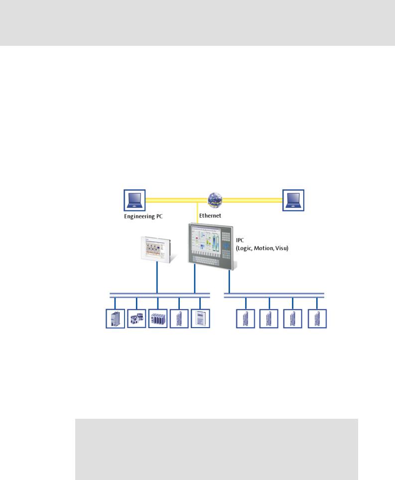
Industrial PCs (IPCs) become more and more important in the field of automation technology. Due to their scaling options and various combinations of visualisation and control on one device, Industrial PCs provide clear advantages for many applications.
Lenze Industrial PCs are available with the following software equipment:
Industrial PC as component (optional with operating system) without any further software
Industrial PC as visualisation system
Industrial PC as control and visualisation system
The "PC-based Automation" system enables the central control of Logic and Motion systems.
For this purpose, Lenze provides coordinated system components:
Industrial PCs as control and visualisation system
–The IPC is the central component of the "PC-based Automation" which control the Logic and Motion functionalities by means of the runtime software.
–The IPC communicates with the field devices via the fieldbus.
–The IPCs are available in different designs.
Note!
Moreover, the Z EL 1xx PLC HMI series is part of the "PC-based Automation" system. These devices differ considerably from the Industrial PCs in performance and various other details. However, the devices of the EL 1xx PLC HMI series are able to perform smaller control tasks.
DMS 4.2 EN 07/2011 TD17
L |
13 |

Control technology | CANopen communication manual
The "PC-based Automation" system
Engineering tools for the Engineering PC
–The Engineering PC communicates with the IPC via Ethernet.
–Different engineering tools serve to configure and parameterise the system.
Fieldbuses
Field devices
14 |
L |
DMS 4.2 EN 07/2011 TD17
|
Control technology | CANopen communication manual |
|
System bus (CAN) / CANopen |
|
CANopen (Logic) / CANopen (Motion) |
|
|
4 |
System bus (CAN) / CANopen |
|
Lenze device series 8200 vector, 9300 and ECS have an on-board system bus (CAN) |
connection. The protocol used there is a subset of CANopen. Thus the devices are not CANopen-conform but can be driven by a CANopen-compatible control under "L-force Controls" - also in connection with other CANopen-compatible nodes.
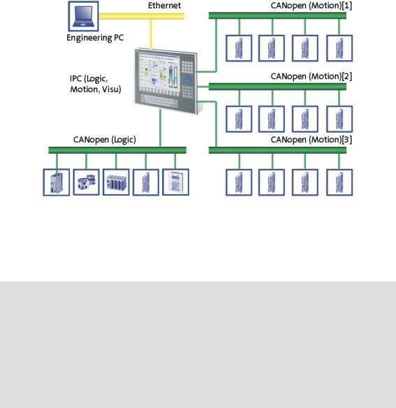
4.1CANopen (Logic) / CANopen (Motion)
Due to the demands on the real-time behaviour of the bus system and the limited transfer capacity, the CANopen bus must be divided into a Logic and a Motion bus.
The Logic bus and the Motion buses can be connected to many different field devices. To establish a CANopen bus, use the Communication card MC-CAN2 ( 18).
Note!
Depending on the required Motion node number and bus cycle time, up to 4
Motion buses can be established.
Only 2 buses are possible for the CS x8xx Command Station IPC series.
Conventions for "PC-based Automation"
•Interface CAN1: CANopen (Logic) or CANopen (Motion)
•Interface CAN2 ... 4: CANopen (Motion)
DMS 4.2 EN 07/2011 TD17
L |
15 |

Control technology | CANopen communication manual
System bus (CAN) / CANopen
CANopen (Logic) / CANopen (Motion)
CANopen (Logic)
The Logic bus is used to operate controllers which
carry out simple movements,
do not have a Motion functionality,
are controlled via PLC functionalities only.
CANopen (Motion)
The Motion bus is used to control controllers which carry out e.g. synchronised movements.
The "L-force Motion" runtime software contains the PLCopen libraries and supports the SoftMotion control to control the "Servo Drives 9400 HighLine CiA402" series and the "ECSxM" axis module.
4.1.1Combination with other bus systems
The CANopen bus system can be combined with PROFIBUS. This makes sense if not all field devices are available for the same bus system or a Motion bus (CANopen) is required in parallel to the PROFIBUS (as Logic bus). The bus systems are synchronised in the control.
Note!
•A mixed operation is only possible with Industrial PCs which have two additional slots for communcation cards. A mixed operation is not possible with the "Command Station".
•Release 2.5 does not facilitate a combination of PROFIBUS and EtherCAT.
•In the control configuration, the PROFIBUS master must be in the first position – upstream to the CANopen motion nodes.
16 |
L |
DMS 4.2 EN 07/2011 TD17

Control technology | CANopen communication manual
System bus (CAN) / CANopen
CANopen (Logic) / CANopen (Motion)
4.1.2Field devices
The Lenze control system supports the following Logic/Motion components:
Standard device |
|
Logic |
Motion |
|
Industrial PCs |
EL x1xx PLC |
z |
- |
|
|
|
|
|
|
|
EL x8xx |
z |
z |
|
|
|
|
|
|
|
CS x8xx |
z |
z |
|
|
|
|
|
|
|
CPC x8xx |
z |
z |
|
|
|
|
|
|
Servo Drives 9400 |
HighLine 1) |
z |
- |
|
|
|
|
|
|
|
HighLine CiA402 |
z |
z |
|
|
|
|
|
|
|
PLC |
z |
- |
|
|
|
|
|
|
Inverter Drives 8400 |
BaseLine |
z |
- |
|
|
|
|
|
|
|
StateLine |
z |
- |
|
|
|
|
|
|
|
HighLine |
z |
- |
|
|
|
|
|
|
|
TopLine |
z |
- |
|
|
|
|
|
|
I/O system IP20 |
EPM-Txxx |
z |
- |
|
|
|
|
|
|
I/O system 1000 |
EPM-Sxxx |
z |
- |
|
|
|
|
|
|
Frequency inverter |
8200 vector |
z |
- |
|
|
|
|
|
|
ECS servo system |
ECSxE |
z |
- |
|
(from firmware version 2.0) |
|
|
|
|
ECSXS (Speed & Torque) |
z |
- |
||
|
||||
|
|
|
|
|
|
ECSxP (Posi & Shaft) |
z |
- |
|
|
|
|
|
|
|
ECSxM (Motion) |
- |
z |
|
|
|
|
|
|
|
ECSxA (Application) |
z |
- |
|
|
|
|
|
1) with technology application (TA)
DMS 4.2 EN 07/2011 TD17
L |
17 |
Control technology | CANopen communication manual
System bus (CAN) / CANopen
CANopen Hardware for your Industrial PC
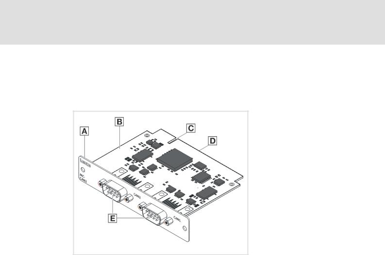
4.2CANopen Hardware for your Industrial PC
Communication card MC-CAN2
The MC-CAN2 communication card is a plug-in card to connect an Industrial PC to a CAN fieldbus. It has two independent CAN bus connections.
A Front panel
B Board
C Coding
D Connection
E Fieldbus connection
MC-CAN2-001
Technical data of the MC-CAN2 communication card ( 21)
18 |
L |
DMS 4.2 EN 07/2011 TD17
Control technology | CANopen communication manual
System bus (CAN) / CANopen CANopen Hardware for your Industrial PC
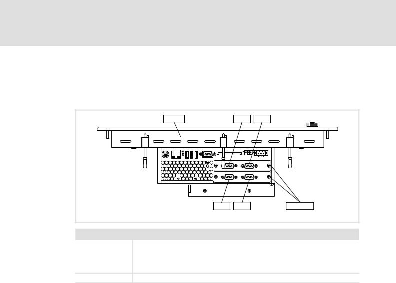
Possible applications
The MC-CAN2 communication card can be plugged into slot 1 and slot 2 of the Industrial PC. Your Industrial PC can have several CANopen communication cards.
Example: The EL x8xx Industrial PC with MC-CAN2 in slots 1 and 2
EL x8xx |
CAN1 |
CAN2 |
|
|
|
|
|
|
CAN3 |
CAN4 |
MC-CAN2 |
|
|
MC-CAN2_ELx8xx |
Legend |
|
|
EL x8xx |
Industrial PC of the EL x8xx series |
|
|
CAN1 ... 4 |
CAN bus connections |
•CAN1: CANopen (Logic) or CANopen (Motion)
•CAN2 ... 4: CANopen (Motion)
MC-CAN2 |
Communication card MC-CAN2 |
DMS 4.2 EN 07/2011 TD17
L |
19 |

Control technology | CANopen communication manual
Technical data
General data
5 |
|
Technical data |
|
|
5.1 |
General data |
|
|
|
|
|
|
|
|
|
|
Field |
Values |
|
|
|
Communication profile |
CANopen (DS301, V4.02) |
|
|
|
|
|
|
|
|
Standards |
CAN, ISO 11898 / EN 50325-4 |
|
|
|
|
|
|
|
|
Network topology |
Line, terminated at both ends with 120 Ω |
|
|
|
|
(e.g. terminated with Sub-D plug of type EWZ0046) |
|
|
|
|
|
|
|
|
Max. number of nodes |
127 |
|
|
|
|
|
|
|
|
Adjustable node addresses |
1 ... 127 |
|
|
|
|
(adjustable for Lenze communication modules via DIP switches) |
|
|
|
|
|
|
|
|
Baud rates [kbps] |
• |
10 |
|
|
|
• |
20 |
|
|
|
• |
50 |
|
|
|
• |
125 |
|
|
|
• |
250 |
|
|
|
• |
500 |
|
|
|
• |
1000 |
|
|
|
|
|
|
|
Parameter data |
Max. 10 client and server SDO channels with 1 ... 8 bytes |
|
|
|
|
|
|
|
|
Cycle time - Motion/CNC task |
1 ... 16 ms |
|
|
|
|
|
|
|
|
Max. number of drives/ms on the |
Max. 3 drives/ms |
|
|
|
Motion bus |
|
|
|
|
|
|
|
|
|
Signal propagation delay - drive |
4 cycles |
|
|
|
control drive |
|
|
|
|
Cross communication |
Only possible with CANopen (Logic) |
|
|
|
|
In case of CANopen (Motion) the communication is executed centrally via |
|
|
|
|
the Industrial PC. |
|
|
|
|
|
|
|
|
Number of DI + DO (bits/ms) |
384 (max. 6 PDOs/ms on the Logic bus) |
|
|
|
|
|
|
|
|
Cycle synchronisation with locked |
+/-10 μs |
|
|
|
PLL (Jitter) |
|
|
|
|
|
|
|
20 |
L |
DMS 4.2 EN 07/2011 TD17
Control technology | CANopen communication manual
Technical data
Technical data of the MC-CAN2 communication card
5.2Technical data of the MC-CAN2 communication card
Field |
Values |
Type within the network |
Master or slave |
|
|
Max. number of nodes |
63 |
|
|
Max. baud rate [kbit/s] |
1000 |
|
|
Bus length |
See Bus cable length ( 22) |
Connection |
SUB-D, 9-pole plug |
|
|
CANopen bus connection (SUB-D, 9-pole plug)
View |
Pin |
Assignment |
Description |
|
1 |
free |
- |
|
|
|
|
|
2 |
LO |
CAN-LOW |
|
|
|
|
|
3 |
CG |
CAN-Ground |
|
|
|
|
|
4 |
free |
- |
|
|
|
|
|
5 |
free |
- |
|
|
|
|
|
6 |
CG |
CAN-Ground |
|
|
|
|
|
7 |
HI |
CAN-HIGH |
|
|
|
|
|
8 |
free |
- |
|
|
|
|
|
9 |
free |
- |
|
|
|
|
5.3Bus cable specification
We recommend to use CAN cables according to ISO 11898-2:
CAN cables according to ISO 11898-2
Cable type |
Paired cable with shield |
|
|
Impedance |
120 Ω (95 ... 140 Ω) |
Cable resistance / cross-section
Cable length ≤ 300 m: ≤ 70 mΩ/m / 0.25 ... 0.34 mm2 (AWG22)
Cable length 301 ... 1000 m: ≤ 40 mΩ/m / 0.5 mm2 (AWG20)
Signal propagation delay |
≤ 5 ns/m |
DMS 4.2 EN 07/2011 TD17
L |
21 |

Control technology | CANopen communication manual
Technical data
Bus cable length
5.4Bus cable length
Note!
•It is absolutely necessary to comply with the permissible cable lengths.
•Observe the reduction of the total cable length due to the signal delay of the repeater. Check use of repeater ( 24)
•If the total cable lengths of the nodes are different at the same baud rate, the smaller value must be used to determine the max. cable length.
5.4.1Total cable length
The total cable length is also specified by the baud rate.
Baud rate [kbps] |
Max. bus length [m] |
|
|
|
|
|
|
9400 Servo |
Inverter |
I/O-System |
I/O-System |
8200 vector |
Servo System |
|
Drives |
Drives 8400 |
IP20 |
1000 |
frequency |
ECS |
|
|
|
(EPM-Txxx) |
(EPM-Sxxx) |
inverter |
|
|
|
|
CAN gateway |
CANopen bus |
|
|
|
|
|
|
coupler |
|
|
10 |
8075 |
- |
5000 |
5000 |
7434 |
- |
|
|
|
|
|
|
|
20 |
4012 |
- |
2500 |
2500 |
3934 |
- |
|
|
|
|
|
|
|
50 |
1575 |
1620 |
1000 |
1000 |
1534 |
1500 |
|
|
|
|
|
|
|
125 |
600 |
600 |
500 |
500 |
614 |
630 |
|
|
|
|
|
|
|
250 |
275 |
260 |
250 |
250 |
274 |
290 |
|
|
|
|
|
|
|
500 |
112 |
90 |
80 |
80 |
104 |
120 |
|
|
|
|
|
|
|
1000 |
12 |
5 |
25 |
25 |
9 |
25 |
|
|
|
|
|
|
|
22 |
L |
DMS 4.2 EN 07/2011 TD17

Control technology | CANopen communication manual
Technical data
Bus cable length
5.4.2Segment cable length
The segment cable length is determined by the used cable cross-section and the number of nodes. Repeaters divide the total cable length into segments. Without a repeater, the segment cable length corresponds to the total cable length.
Max. number of |
Cable cross-section (interpolation is permissible) |
|
|||
nodes per segment |
|
|
|
|
|
0.25 mm2 |
|
0.50 mm2 |
0.75 mm2 |
1.00 mm2 |
|
|
|
||||
|
(AWG 24) |
|
(AWG 21) |
(AWG 19) |
(AWG 18) |
2 |
240 m |
|
430 m |
650 m |
940 m |
|
|
|
|
|
|
5 |
230 m |
|
420 m |
640 m |
920 m |
|
|
|
|
|
|
10 |
230 m |
|
410 m |
620 m |
900 m |
|
|
|
|
|
|
20 |
210 m |
|
390 m |
580 m |
850 m |
|
|
|
|
|
|
32 |
200 m |
|
360 m |
550 m |
800 m |
|
|
|
|
|
|
63 |
170 m |
|
310 m |
470 m |
690 m |
|
|
|
|
|
|
100 |
150 m |
|
270 m |
410 m |
600 m |
|
|
|
|
|
|
Example: Selection help |
|
|
|
|
|
|
|
|
|
|
|
Given: |
|
|
|
|
|
Total cable length to be |
200 m |
|
|
||
implemented |
|
|
|
|
|
|
|
|
|
|
|
Number of nodes |
|
63 |
|
|
|
|
|
|
|
|
|
|
|
|
|
|
|
Results |
|
|
|
|
|
Max. possible baud rate |
250 kbps |
|
|
||
|
|
(derived from table Total cable length ( 22)) |
|
||
Required cable cross-section |
0.30 mm2 (AWG23) |
|
|
||
(interpolated) |
|
(derived from table Segment cable length ( 23)) |
|
||
Cable cross-section - standard CAN |
0.34 mm2 (AWG22) |
|
|
||
cable |
|
Bus cable specification ( 21) |
|
||
|
|
|
|||
DMS 4.2 EN 07/2011 TD17
L |
23 |

Control technology | CANopen communication manual
Technical data
Bus cable length
5.4.3Check use of repeater
Compare the values from the tables Total cable length ( 22) and Segment cable length
( 23).
If the total segment cable length is shorter than the total cable length to be implemented, either repeaters must be used or the cable cross-section must be increased.
If, due to the use of repeaters, the max. possible total cable length is reduced to a value smaller than the total cable length to be implemented, either the cable cross-section must be increased and the number of repeaters must be reduced or the baud rate must be reduced.
The use of another repeater is recommended as ...
–Service interface
Advantage: Trouble-free coupling during bus operation is possible.
–Calibration interface
Advantage: The calibration/programming unit remains electrically isolated.
Example
Given
Total cable length to be |
450 m |
implemented |
|
|
|
Number of nodes |
32 |
|
|
Cable cross-section |
0.50 mm2 (AWG 21) |
Baud rate |
125 kbit/s |
|
|
Used repeater |
Lenze repeater EMF2176IB |
|
|
Reduction of the max. total cable |
30 m |
length per repeater (EMF2176IB) |
|
|
|
|
|
Results |
|
Max. possible total cable length |
600 m |
|
(cp. table Total cable length ( 22)) |
Max. segment cable length |
360 m |
|
(cp. table Segment cable length ( 23)) |
Comparison |
The max. segment cable length is shorter than the total cable length to be |
|
implemented. |
|
|
Conclusion |
After the determined max. segment cable length of 360 m at the latest, a |
|
repeater must be used. |
|
|
|
|
Results with 1 repeater |
|
Max. possible total cable length |
570 m |
|
(Reduction of the Total cable length ( 22) by 30 m) |
Total segment cable length |
720 m |
|
|
Comparison |
Both the possible total cable length and the segment cable length are longer |
|
than the total cable length to be implemented. |
|
|
Conclusion |
One repeater suffices to implement the total cable length of 450 m. |
|
|
24 |
L |
DMS 4.2 EN 07/2011 TD17

Control technology | CANopen communication manual
Planning the CANopen network
6 |
Planning the CANopen network |
Before establishing a CANopen network, create a plan of your Logic bus and/or your Motion buses.
For this purpose, create an overview screen of the planned CANopen network with all field devices to be implemented. Start with the Industrial PC and arrange the other field devices below it. (see Example of an overview screen ( 28)).
Provide the following data for each device:
Type |
Type designation of the field device |
|
|
|
|
Used CAN interface of the device |
"Logic before Motion": |
|
|
• |
Always connect an existing Logic bus to the 1st CAN interface (CAN1). |
|
• |
Motion buses, however, can be connected to every CAN interface. |
|
|
CANopen (Logic) / CANopen (Motion) ( 15) |
Unambiguous CAN node address • If system bus (CAN) devices are used, max. 63 nodes/node addresses are possible.
•With CANopen-compliant devices, up to 127 nodes/node addresses are possible.
Note: Do not use the node address 1, in order to avoid unintentional mistakes and conflicts with a device containing the factory adjustment.
Baud rate |
• |
The baud rate applies to all nodes of the CANopen network. |
|
• 50, 125, 250 and 500 kbit/s are supported by all device types of the system. |
|
|
• |
Observe the dependency between bus cable length and baud rate. Bus |
|
|
cable length ( 22) |
Master role of the device |
• |
An NMT master sets itself and then the NMT slaves to the "Operational" state. |
(NMT master/sync master) |
|
In this state, process data can be communicated. Generally, there can be an |
|
|
optional number of NMT masters on one CANopen bus. |
|
• A sync master cyclically sends a sync telegram providing for an exactly |
|
|
|
simultaneous processing of process data and/or a simultaneous task start in |
|
|
all sync receivers. |
|
• Via CAN synchronisation you can influence the exact time of the following |
|
|
|
events in the field device: |
|
|
– Acceptance and transmission of sync-controlled PDOs |
|
|
– Starting time of the task of the application (only possible for Servo Drives |
|
|
9400) |
|
• You only need to use CAN synchronisation on the Logic bus if an exact |
|
|
|
simultaneity in the range of milliseconds is of importance. A mere operating |
|
|
periphery (operator button, control lamps, etc.) does not require CAN |
|
|
synchronisation. |
|
|
|
CAN objects and COB-IDs |
• |
Plan your COB-IDs according to the CANopen DS301 communication profile. |
|
|
This convention is optimised for the communication with a central master |
|
|
device. COB-IDs acc. to DS301 ( 26) |
|
• Up to 4 PDOs per device can be identified with this scheme. If you require |
|
|
|
more, e.g. for a modular I/O system with more than 8 modules, you can add |
|
|
them later. |
|
• You can easily assign the node during the bus diagnostics by means of the |
|
|
|
COB-IDs. |
|
• COB-ID = basic identifier + node address |
|
DMS 4.2 EN 07/2011 TD17
L |
25 |

Control technology | CANopen communication manual
Planning the CANopen network
Observe device-specific information on CAN configuration provided in the documentation of the field devices to be integrated.
COB-IDs acc. to DS301
|
|
|
|
|
|
|
Object |
|
Direction |
Basic identifier |
|
||
|
|
from the drive |
to the drive |
Dec |
|
Hex |
NMT |
|
|
|
0 |
|
0 |
|
|
|
|
|
|
|
Sync |
|
|
|
128 |
|
80 |
|
|
|
|
|
|
|
Time Stamp |
|
|
|
256 |
|
100 |
|
|
|
|
|
|
|
Emergency |
|
z |
|
128 |
|
80 |
|
|
|
|
|
|
|
PDO1 |
TPDO1 |
z |
|
384 |
|
180 |
(process data channel 1) |
|
|
|
|
|
|
RPDO1 |
|
z |
512 |
|
200 |
|
|
|
|
||||
|
|
|
|
|
|
|
PDO2 |
TPDO2 |
z |
|
640 |
|
280 |
(process data channel 2) |
|
|
|
|
|
|
RPDO2 |
|
z |
768 |
|
300 |
|
|
|
|
||||
|
|
|
|
|
|
|
PDO3 |
TPDO3 |
z |
|
896 |
|
380 |
(process data channel 3) |
|
|
|
|
|
|
RPDO3 |
|
z |
1024 |
|
400 |
|
|
|
|
||||
|
|
|
|
|
|
|
PDO4 |
TPDO4 |
z |
|
1152 |
|
480 |
(process data channel 4) |
|
|
|
|
|
|
RPDO4 |
|
z |
1280 |
|
500 |
|
|
|
|
||||
|
|
|
|
|
|
|
SDO |
|
z |
|
1408 |
|
580 |
(parameter data channel 1) |
|
|
|
|
|
|
|
|
z |
1536 |
|
600 |
|
|
|
|
|
|||
|
|
|
|
|
|
|
NMT Error Control |
|
z |
|
1792 |
|
700 |
|
|
|
|
|
|
|
Note!
In system bus (CAN) devices, two SDO channels are permanently active, in CANopen devices, only one by default.
When using CANopen devices, activate a second SDO channel for accesses of the »Engineer« or »Global Drive Control«. Otherwise the communication with the device will be interfered if you go online with the »Engineer« or the »Global Drive Control«, while the IPC has also access.
26 |
L |
DMS 4.2 EN 07/2011 TD17

Control technology | CANopen communication manual
Planning the CANopen network
The COB-IDs for your CANopen network can be calculated according to the following formula:
COB-ID = basic identifier + node address
Basic identifier - 9400 Servo Drives ( 30) Basic identifier - 8400 Inverter Drives ( 31)
Basic identifier - I/O system IP20 (EPM-Txxx) ( 32) Basic identifier - I/O system 1000 (EPM-Sxxx) ( 33)
Basic identifier - 8200 vector with fieldbus function module CANopen E82ZAFUC0xx
( 34)
Basic identifier - ECS servo system ( 36)
DMS 4.2 EN 07/2011 TD17
L |
27 |

Control technology | CANopen communication manual
Planning the CANopen network
Example of an overview screen
6.1Example of an overview screen
The illustration shows you an example of an overview screen for planning a CANopen network:
28 |
L |
DMS 4.2 EN 07/2011 TD17

Control technology | CANopen communication manual
Planning the CANopen network
Device specifications of the field devices
6.2Device specifications of the field devices
When planning your CANopen network, consider the device specifications of the implemented field devices.
Overview of the device specifications when being operated subordinate to a control
|
Servo Drives 9400 |
Inverter Drives 8400 |
I/O-System IP20 |
|
|
|
(EPM-Txxx) |
CAN interface |
on board and/or |
on board |
on board |
|
CANopen module |
|
|
|
|
|
|
Available PDOs |
4 Transmit (Tx) + |
3 Transmit (Tx) + |
10 Transmit (Tx) + |
|
4 Receive (Rx) |
3 Receive (Rx) |
10 Receive (Rx) |
|
|
|
|
Can unused PDOs be |
yes |
yes |
yes |
deactivated? |
|
|
|
|
|
|
|
Can PDO COB-IDs be freely |
yes |
yes |
yes |
selected? |
|
|
|
|
|
|
|
Can PDO transfer characteristics |
yes |
yes |
yes |
be adjusted? |
|
|
|
|
|
|
|
Available SDO channels |
1 ex works (fixed), |
2 ex works (fixed) |
2 ex works |
|
9 further can be activated |
|
(Only possible with V1.3 |
|
|
|
in CANopen mode.) |
|
|
|
|
Can SDO COB-IDs be freely |
only for channel 2 ... 10 |
no |
no |
selected? |
|
|
|
|
|
|
|
|
I/O-System 1000 |
8200 vector frequency |
ECS servo system |
|
|
(EPM-Sxxx) |
inverter |
|
|
CAN interface |
on board |
Fieldbusfunction module |
2 x CAN on board: |
|
|
|
CANopen E82ZAFUC0xx |
• |
Terminal X4: Motion |
|
|
|
|
bus (CAN) |
|
|
|
• |
Terminal X14: System |
|
|
|
|
bus (CAN) |
|
|
|
|
|
Available PDOs |
10 Transmit (Tx) + |
3 Transmit (Tx) + |
1 Transmit (Tx) + |
|
|
10 Receive (Rx) |
3 Receive (Rx) |
1 Receive (Rx) |
|
|
|
|
|
|
Can unused PDOs be |
yes |
yes |
no |
|
deactivated? |
|
|
|
|
|
|
|
|
|
Can PDO COB-IDs be freely |
yes |
yes |
yes |
|
selected? |
|
|
|
|
|
|
|
|
|
Can PDO transfer characteristics |
yes |
yes |
yes |
|
be adjusted? |
|
|
|
|
|
|
|
|
|
Available SDO channels |
1 ex works (fixed), |
1 ex works (fixed), |
2 ex works (fixed) |
|
|
1 more can be activated |
1 more can be activated |
|
|
|
|
|
|
|
Can SDO COB-IDs be freely |
no |
no |
no |
|
selected? |
|
|
|
|
|
|
|
|
|
DMS 4.2 EN 07/2011 TD17
L |
29 |

Control technology | CANopen communication manual
Planning the CANopen network
Device specifications of the field devices
6.2.1Special features of the Servo Drives 9400
The parameter data channel 1 is always active.
The optional parameter data channels 2 ... 10 can be activated via the subcodes of the codes Cxx372 and Cxx373.
SDO identifier |
Code |
CANopen SDO server Rx identifier |
C00372: CAN on board |
|
|
|
C13372: Module in slot 1 |
|
|
|
C14372: Module in slot 2 |
|
|
CANopen SDO server Tx identifier |
C00373: CAN on board |
|
|
|
C13373: Module in slot 1 |
|
|
|
C14373: Module in slot 2 |
|
|
If bit 31 is set (0x8nnnnnnnhex), the corresponding SDO server is deactivated.
In order to change the COB-ID of a currently active parameter data channel, you have to first deactivate it and then activate it with a changed COB-ID. Both processes must be rendered effective by a "Reset Node" command via C00002.
Basic identifier - 9400 Servo Drives
The default setting of the basic identifier is as follows:
Object |
|
Direction |
Basic identifier |
|
||
|
|
from the drive |
to the drive |
dec |
|
hex |
NMT |
|
|
|
0 |
|
0 |
|
|
|
|
|
|
|
Sync 1) |
|
|
|
128 |
|
80 |
|
|
|
|
|
|
|
Emergency |
|
z |
|
128 |
|
80 |
|
|
|
|
|
|
|
PDO1 |
TPDO1 |
z |
|
384 |
|
180 |
(process data channel 1) |
|
|
|
|
|
|
RPDO1 |
|
z |
512 |
|
200 |
|
|
|
|
||||
|
|
|
|
|
|
|
PDO2 |
TPDO2 |
z |
|
640 |
|
280 |
(process data channel 2) |
|
|
|
|
|
|
RPDO2 |
|
z |
768 |
|
300 |
|
|
|
|
||||
|
|
|
|
|
|
|
PDO3 |
TPDO3 |
z |
|
896 |
|
380 |
(process data channel 3) |
|
|
|
|
|
|
RPDO3 |
|
z |
1024 |
|
400 |
|
|
|
|
||||
|
|
|
|
|
|
|
PDO4 |
TPDO4 |
z |
|
1152 |
|
480 |
(process data channel 4) |
|
|
|
|
|
|
RPDO4 |
|
z |
1280 |
|
500 |
|
|
|
|
||||
|
|
|
|
|
|
|
SDO1 |
TSDO1 |
z |
|
1408 |
|
580 |
(parameter data channel 1) |
|
|
|
|
|
|
RSDO1 |
|
z |
1536 |
|
600 |
|
|
|
|
||||
|
|
|
|
|
|
|
SDO2 ... 10 |
TSDOx |
z |
|
1472 |
|
5C0 |
(parameter data channel 2 ... 10) |
|
|
|
|
|
|
RSDOx |
|
z |
1600 |
|
640 |
|
|
|
|
||||
|
|
|
|
|
|
|
Node guarding, heartbeat |
|
z |
|
1792 |
|
700 |
|
|
|
|
|
|
|
1) When creating the sync transmit/receive identifier manually, observe the use of the emergency telegram because of the same COB-ID.
30 |
L |
DMS 4.2 EN 07/2011 TD17
Loading...