


 Loading...
EDSMF2133IB
.G÷h
Ä.G÷hä
L−force Communication
Communication Manual
PROFIBUS−DP
EMF2133IB
Communication module
l

iContents
1 |
About this documentation . . . . . . . . . . . . . . . . . . . . . . . . . . . . . . . . . . . . . . . . . . . . . . . . . . |
5 |
||
|
1.1 |
Document history . . . . . . . . . . . . . . . . . . . . . . . . . . . . . . . . . . . . . . . . . . . . . . . . . . . . |
6 |
|
|
1.2 |
Conventions used . . . . . . . . . . . . . . . . . . . . . . . . . . . . . . . . . . . . . . . . . . . . . . . . . . . . |
7 |
|
|
1.3 |
Terminology used . . . . . . . . . . . . . . . . . . . . . . . . . . . . . . . . . . . . . . . . . . . . . . . . . . . . |
8 |
|
|
1.4 |
Notes used . . . . . . . . . . . . . . . . . . . . . . . . . . . . . . . . . . . . . . . . . . . . . . . . . . . . . . . . . . |
9 |
|
2 |
Safety instructions . . . . . . . . . . . . . . . . . . . . . . . . . . . . . . . . . . . . . . . . . . . . . . . . . . . . . . . . . |
10 |
||
|
2.1 |
General safety information . . . . . . . . . . . . . . . . . . . . . . . . . . . . . . . . . . . . . . . . . . . . |
10 |
|
|
2.2 |
Device− and application−specific safety instructions . . . . . . . . . . . . . . . . . . . . . . . . |
11 |
|
|
2.3 |
Residual hazards . . . . . . . . . . . . . . . . . . . . . . . . . . . . . . . . . . . . . . . . . . . . . . . . . . . . . |
11 |
|
3 |
Product description . . . . . . . . . . . . . . . . . . . . . . . . . . . . . . . . . . . . . . . . . . . . . . . . . . . . . . . . |
12 |
||
|
3.1 |
Application as directed . . . . . . . . . . . . . . . . . . . . . . . . . . . . . . . . . . . . . . . . . . . . . . . |
12 |
|
|
3.2 |
Identification . . . . . . . . . . . . . . . . . . . . . . . . . . . . . . . . . . . . . . . . . . . . . . . . . . . . . . . . |
13 |
|
|
3.3 |
Product features . . . . . . . . . . . . . . . . . . . . . . . . . . . . . . . . . . . . . . . . . . . . . . . . . . . . . |
14 |
|
|
3.4 |
Connections and interfaces . . . . . . . . . . . . . . . . . . . . . . . . . . . . . . . . . . . . . . . . . . . . |
15 |
|
4 |
Technical data |
. . . . . . . . . . . . . . . . . . . . . . . . . . . . . . . . . . . . . . . . . . . . . . . . . . . . . . . . . . . . |
16 |
|
|
4.1 |
General data . . . . . . . . . . . . . . . . . . . . . . . . . . . . . . . . . . . . . . . . . . . . . . . . . . . . . . . . |
16 |
|
|
4.2 |
Protective insulation . . . . . . . . . . . . . . . . . . . . . . . . . . . . . . . . . . . . . . . . . . . . . . . . . . |
17 |
|
|
4.3 |
Communication time . . . . . . . . . . . . . . . . . . . . . . . . . . . . . . . . . . . . . . . . . . . . . . . . . |
18 |
|
|
|
4.3.1 |
Processing time 820X . . . . . . . . . . . . . . . . . . . . . . . . . . . . . . . . . . . . . . . . . . |
18 |
|
|
4.3.2 |
Processing time 821X / 822X / 824X / 8200 vector . . . . . . . . . . . . . . . . . |
19 |
|
|
4.3.3 |
Processing time 93XX / ECSxS . . . . . . . . . . . . . . . . . . . . . . . . . . . . . . . . . . |
19 |
|
|
4.3.4 |
Processing time Drive PLC / 9300 Servo PLC / ECSxA . . . . . . . . . . . . . . . . |
19 |
|
4.4 |
Dimensions . . . . . . . . . . . . . . . . . . . . . . . . . . . . . . . . . . . . . . . . . . . . . . . . . . . . . . . . . . |
20 |
|
5 |
Installation . . |
. . . . . . . . . . . . . . . . . . . . . . . . . . . . . . . . . . . . . . . . . . . . . . . . . . . . . . . . . . . . . |
21 |
|
|
5.1 |
Mechanical installation . . . . . . . . . . . . . . . . . . . . . . . . . . . . . . . . . . . . . . . . . . . . . . . . |
22 |
|
|
5.2 |
Electrical installation . . . . . . . . . . . . . . . . . . . . . . . . . . . . . . . . . . . . . . . . . . . . . . . . . . |
23 |
|
|
|
5.2.1 |
Wiring according to EMC (CE−typical drive system) . . . . . . . . . . . . . . . . . |
23 |
|
|
5.2.2 |
Wiring with a host (master) . . . . . . . . . . . . . . . . . . . . . . . . . . . . . . . . . . . . |
24 |
|
|
5.2.3 |
Connection of the PROFIBUS . . . . . . . . . . . . . . . . . . . . . . . . . . . . . . . . . . . |
27 |
|
|
5.2.4 |
Voltage supply . . . . . . . . . . . . . . . . . . . . . . . . . . . . . . . . . . . . . . . . . . . . . . |
28 |
|
|
5.2.5 |
Cable cross−sections and screw−tightening torques . . . . . . . . . . . . . . . . . |
30 |
6 |
Commissioning . . . . . . . . . . . . . . . . . . . . . . . . . . . . . . . . . . . . . . . . . . . . . . . . . . . . . . . . . . . |
31 |
||
|
6.1 |
Before switching on . . . . . . . . . . . . . . . . . . . . . . . . . . . . . . . . . . . . . . . . . . . . . . . . . . |
31 |
|
|
6.2 |
Initial switch−on . . . . . . . . . . . . . . . . . . . . . . . . . . . . . . . . . . . . . . . . . . . . . . . . . . . . . . |
32 |
|
|
6.3 |
Configuring the host system (master) . . . . . . . . . . . . . . . . . . . . . . . . . . . . . . . . . . . |
34 |
|
|
6.4 |
Activating the bus terminating resistor . . . . . . . . . . . . . . . . . . . . . . . . . . . . . . . . . . |
37 |
|
2 |
l |
EDSMF2133IB EN 5.0

Contents i
|
6.5 |
Setting the software compatibility . . . . . . . . . . . . . . . . . . . . . . . . . . . . . . . . . . . . . . |
37 |
|
|
6.6 |
Preparing the standard device for communication . . . . . . . . . . . . . . . . . . . . . . . . |
38 |
|
|
|
6.6.1 |
Frequency inverter 82XX / 8200 vector . . . . . . . . . . . . . . . . . . . . . . . . . . . |
38 |
|
|
6.6.2 |
93XX servo inverter / 9300 Servo PLC . . . . . . . . . . . . . . . . . . . . . . . . . . . . |
39 |
|
|
6.6.3 |
Drive PLC . . . . . . . . . . . . . . . . . . . . . . . . . . . . . . . . . . . . . . . . . . . . . . . . . . . . |
40 |
|
|
6.6.4 |
Axis modules ECSxS / ECSxA . . . . . . . . . . . . . . . . . . . . . . . . . . . . . . . . . . . . |
41 |
|
6.7 |
Setting the node address . . . . . . . . . . . . . . . . . . . . . . . . . . . . . . . . . . . . . . . . . . . . . |
42 |
|
|
|
6.7.1 |
Setting via code . . . . . . . . . . . . . . . . . . . . . . . . . . . . . . . . . . . . . . . . . . . . . . |
42 |
|
|
6.7.2 |
Settings via DIP switch . . . . . . . . . . . . . . . . . . . . . . . . . . . . . . . . . . . . . . . . |
42 |
|
|
6.7.3 |
Settings by a master (class 2) . . . . . . . . . . . . . . . . . . . . . . . . . . . . . . . . . . . |
43 |
|
6.8 |
Connecting the mains voltage . . . . . . . . . . . . . . . . . . . . . . . . . . . . . . . . . . . . . . . . . . |
44 |
|
7 |
Process data transfer . . . . . . . . . . . . . . . . . . . . . . . . . . . . . . . . . . . . . . . . . . . . . . . . . . . . . . . |
45 |
||
|
7.1 |
Lenze device control . . . . . . . . . . . . . . . . . . . . . . . . . . . . . . . . . . . . . . . . . . . . . . . . . |
46 |
|
|
|
7.1.1 |
Setpoint source selection . . . . . . . . . . . . . . . . . . . . . . . . . . . . . . . . . . . . . . |
46 |
|
|
7.1.2 |
Process data signals for 82XX frequency inverters . . . . . . . . . . . . . . . . . . |
47 |
|
|
7.1.3 |
Process data signals for 8200 vector frequency inverters . . . . . . . . . . . . |
52 |
|
|
7.1.4 |
Process data signal for 9300 servo inverters . . . . . . . . . . . . . . . . . . . . . . . |
57 |
|
|
7.1.5 |
Process data signals for 9300 Servo PLC and Drive PLC . . . . . . . . . . . . . . |
63 |
|
|
7.1.6 |
Process data signals for axis modules ECSxS / ECSxA . . . . . . . . . . . . . . . |
67 |
|
7.2 |
DRIVECOM control . . . . . . . . . . . . . . . . . . . . . . . . . . . . . . . . . . . . . . . . . . . . . . . . . . . . |
68 |
|
|
|
7.2.1 |
Provide DRIVECOM compatibility . . . . . . . . . . . . . . . . . . . . . . . . . . . . . . . |
68 |
|
|
7.2.2 |
DRIVECOM state machine . . . . . . . . . . . . . . . . . . . . . . . . . . . . . . . . . . . . . . |
69 |
|
|
7.2.3 |
DRIVECOM control word . . . . . . . . . . . . . . . . . . . . . . . . . . . . . . . . . . . . . . . |
71 |
|
|
7.2.4 |
DRIVECOM status word . . . . . . . . . . . . . . . . . . . . . . . . . . . . . . . . . . . . . . . . |
73 |
|
|
7.2.5 |
Bit control commands . . . . . . . . . . . . . . . . . . . . . . . . . . . . . . . . . . . . . . . . . |
75 |
|
|
7.2.6 |
Status bits . . . . . . . . . . . . . . . . . . . . . . . . . . . . . . . . . . . . . . . . . . . . . . . . . . . |
76 |
|
7.3 |
PROFIdrive control . . . . . . . . . . . . . . . . . . . . . . . . . . . . . . . . . . . . . . . . . . . . . . . . . . . . |
77 |
|
|
|
7.3.1 |
Establishing PROFIdrive compatibility . . . . . . . . . . . . . . . . . . . . . . . . . . . |
77 |
|
|
7.3.2 |
PROFIdrive state machine . . . . . . . . . . . . . . . . . . . . . . . . . . . . . . . . . . . . . . |
78 |
|
|
7.3.3 |
PROFIdrive control word . . . . . . . . . . . . . . . . . . . . . . . . . . . . . . . . . . . . . . . |
79 |
|
|
7.3.4 |
PROFIdrive status word . . . . . . . . . . . . . . . . . . . . . . . . . . . . . . . . . . . . . . . . |
81 |
8 |
Parameter data transfer . . . . . . . . . . . . . . . . . . . . . . . . . . . . . . . . . . . . . . . . . . . . . . . . . . . . |
82 |
||
|
8.1 |
Lenze parameter sets . . . . . . . . . . . . . . . . . . . . . . . . . . . . . . . . . . . . . . . . . . . . . . . . . |
83 |
|
|
|
8.1.1 |
Parameter sets for 82XX controllers . . . . . . . . . . . . . . . . . . . . . . . . . . . . . . |
83 |
|
|
8.1.2 |
Parameter sets for 8200 vector controller . . . . . . . . . . . . . . . . . . . . . . . . . |
84 |
|
|
8.1.3 |
Parameter sets for controller 93XX . . . . . . . . . . . . . . . . . . . . . . . . . . . . . . |
85 |
|
|
8.1.4 |
Parameter sets for Drive PLC and ECSxS / ECSxA axis modules . . . . . . . |
86 |
EDSMF2133IB EN 5.0
l 3

iContents
|
8.2 |
DRIVECOM parameter data channel . . . . . . . . . . . . . . . . . . . . . . . . . . . . . . . . . . . . . |
87 |
|
|
|
8.2.1 |
Addressing of the parameter data . . . . . . . . . . . . . . . . . . . . . . . . . . . . . . . |
87 |
|
|
8.2.2 |
Addressing of the Lenze parameters . . . . . . . . . . . . . . . . . . . . . . . . . . . . . |
87 |
|
|
8.2.3 |
Telegram structure . . . . . . . . . . . . . . . . . . . . . . . . . . . . . . . . . . . . . . . . . . . . |
87 |
|
|
8.2.4 |
Error codes (DRIVECOM) . . . . . . . . . . . . . . . . . . . . . . . . . . . . . . . . . . . . . . . |
91 |
|
|
8.2.5 |
Reading parameters . . . . . . . . . . . . . . . . . . . . . . . . . . . . . . . . . . . . . . . . . . . |
92 |
|
|
8.2.6 |
Writing parameters . . . . . . . . . . . . . . . . . . . . . . . . . . . . . . . . . . . . . . . . . . . |
94 |
|
8.3 |
PROFIdrive parameter data channel . . . . . . . . . . . . . . . . . . . . . . . . . . . . . . . . . . . . . |
96 |
|
|
|
8.3.1 |
PROFIdrive DP−V1 . . . . . . . . . . . . . . . . . . . . . . . . . . . . . . . . . . . . . . . . . . . . . |
97 |
|
|
8.3.2 |
Error codes (PROFIdrive) . . . . . . . . . . . . . . . . . . . . . . . . . . . . . . . . . . . . . . . . |
109 |
|
8.4 |
Consistent parameter data . . . . . . . . . . . . . . . . . . . . . . . . . . . . . . . . . . . . . . . . . . . . . |
110 |
|
9 |
Diagnostics . . |
. . . . . . . . . . . . . . . . . . . . . . . . . . . . . . . . . . . . . . . . . . . . . . . . . . . . . . . . . . . . . |
112 |
|
|
9.1 |
LED status displays . . . . . . . . . . . . . . . . . . . . . . . . . . . . . . . . . . . . . . . . . . . . . . . . . . |
112 |
|
|
9.2 |
Troubleshooting and fault elimination . . . . . . . . . . . . . . . . . . . . . . . . . . . . . . . . . . . |
113 |
|
|
|
9.2.1 |
Controller is inhibited . . . . . . . . . . . . . . . . . . . . . . . . . . . . . . . . . . . . . . . . . |
113 |
|
|
9.2.2 |
Checking PROFIBUS . . . . . . . . . . . . . . . . . . . . . . . . . . . . . . . . . . . . . . . . . . . |
115 |
|
|
9.2.3 |
Activation of communication module . . . . . . . . . . . . . . . . . . . . . . . . . . . . |
116 |
|
|
9.2.4 |
Reset fault (TRIP) . . . . . . . . . . . . . . . . . . . . . . . . . . . . . . . . . . . . . . . . . . . . . |
117 |
|
9.3 |
Monitoring with interrupted PROFIBUS communication . . . . . . . . . . . . . . . . . . . . |
118 |
|
|
|
9.3.1 |
Permanent interruption of communication . . . . . . . . . . . . . . . . . . . . . . . |
118 |
|
|
9.3.2 |
Short−time interruption of communication . . . . . . . . . . . . . . . . . . . . . . . . |
119 |
10 |
Codes . . . . . . . |
. . . . . . . . . . . . . . . . . . . . . . . . . . . . . . . . . . . . . . . . . . . . . . . . . . . . . . . . . . . . . |
120 |
|
|
10.1 |
Overview . . . . . . . . . . . . . . . . . . . . . . . . . . . . . . . . . . . . . . . . . . . . . . . . . . . . . . . . . . . . |
120 |
|
|
10.2 |
Monitoring codes . . . . . . . . . . . . . . . . . . . . . . . . . . . . . . . . . . . . . . . . . . . . . . . . . . . . . |
122 |
|
|
10.3 |
Diagnostics codes . . . . . . . . . . . . . . . . . . . . . . . . . . . . . . . . . . . . . . . . . . . . . . . . . . . . |
124 |
|
11 |
Index table . . |
. . . . . . . . . . . . . . . . . . . . . . . . . . . . . . . . . . . . . . . . . . . . . . . . . . . . . . . . . . . . . |
125 |
|
|
11.1 |
DRIVECOM profile parameter . . . . . . . . . . . . . . . . . . . . . . . . . . . . . . . . . . . . . . . . . . . |
125 |
|
12 |
Appendix . . . |
. . . . . . . . . . . . . . . . . . . . . . . . . . . . . . . . . . . . . . . . . . . . . . . . . . . . . . . . . . . . . |
126 |
|
|
12.1 |
Parallel operation of AIF and FIF interfaces . . . . . . . . . . . . . . . . . . . . . . . . . . . . . . . . |
126 |
|
|
12.2 |
Accessories . . . . . . . . . . . . . . . . . . . . . . . . . . . . . . . . . . . . . . . . . . . . . . . . . . . . . . . . . . |
128 |
|
13 |
Index |
. . . . . . . |
. . . . . . . . . . . . . . . . . . . . . . . . . . . . . . . . . . . . . . . . . . . . . . . . . . . . . . . . . . . . . |
129 |
4 |
l |
EDSMF2133IB EN 5.0

About this documentation |
1 |
|
|
0Fig. 0Tab. 0
1About this documentation
Contents
This documentation only contains descriptions for the EMF2133IB communication module (PROFIBUS−DP).
)Note!
This documentation supplements the mounting instructions supplied with the communication module and the documentations for the standard devices used.
The mounting instructions contain safety instructions which must be observed!
ƒThe features and functions of the communication module are described in detail.
ƒExamples illustrate typical applications.
ƒFurthermore this documentation contains the following:
–Safety instructions that must be observed.
–Key technical data relating to the communication module
–Information on versions of Lenze standard devices to be used.
–Notes on troubleshooting and fault elimination
The theoretical correlations are only explained in so far as they are necessary for comprehending the function of the function module.
This documentation does not describe the software of an original equipment manufacturer. No responsibility is taken for corresponding information given in this manual. Information on how to use the software can be obtained from the documents of the host system (master).
All brand names mentioned in this manual are trademarks of their respective companies.
Validity information
The information given in this documentation is valid for the following devices:
Communication module |
Type designation |
From hardware version |
From software version |
|
PROFIBUS−DP |
EMF2133IB |
V2 |
0x |
|
Target group
This documentation is intended for all persons who plan, install, commission and maintain the networking and remote service of a machine.
I Tip!
Information and auxiliary devices around the Lenze products can be found in the download area at
http://www.Lenze.com
EDSMF2133IB EN 5.0
l 5

1About this documentation
Document history
1.1Document history
Material no. |
Version |
|
|
Description |
|
|
− |
1.0 |
|
11/2001 |
TD06 |
First edition |
|
|
|
|
|
|
|
|
− |
2.0 |
|
06/2004 |
TD06 |
l As of software version 1.2: Code C1882 added |
|
|
|
|
|
|
l Complete revision: |
|
|
|
|
|
|
– Layout change |
|
|
|
|
|
|
– New German orthography |
|
|
|
|
|
|
|
|
− |
4.0 |
|
12/2006 |
TD17 |
l As of software version 1.3: code C1883 added |
|
|
|
|
|
|
l Structural and editorial adjustments |
|
|
|
|
|
|
Extended descriptions for the use on the ECS servo system. |
|
|
|
|
|
|
|
|
.G÷h |
5.0 |
|
09/2011 |
TD14 |
l Extended information on PROFIBUS DP−V1. |
|
|
|
|
|
|
l Structural and editorial adjustments |
|
Your opinion is important to us!
These instructions were created to the best of our knowledge and belief to give you the best possible support for handling our product.
If you have suggestions for improvement, please e−mail us to:
feedback−docu@Lenze.de
Thank you for your support.
Your Lenze documentation team
6 |
l |
EDSMF2133IB EN 5.0

About this documentation |
1 |
Conventions used
1.2Conventions used
This documentation uses the following conventions to distinguish between different types of information:
Type of information |
Identification |
Examples/notes |
|
|
Spelling of numbers |
|
|
|
|
|
|
|
|
|
|
Decimal separator |
Point |
In general, the decimal point is used. |
|
|
|
|
For instance: 1234.56 |
|
|
|
|
|
|
|
Decimal |
Standard notation |
For example: 1234 |
|
|
|
|
|
|
|
Hexadecimal |
0x[0 ... 9, A ... F] |
For example: 0x60F4 |
|
|
|
|
|
|
|
Binary |
In quotation marks |
For example: ´100´ |
|
|
l Nibble |
Point |
For example: ´0110.0100´ |
|
|
|
|
|
|
Text |
|
|
|
|
|
|
|
|
|
|
Program name |
» « |
PC software |
|
|
|
|
For example: »Engineer«, »Global Drive |
|
|
|
|
Control« (GDC) |
|
|
|
|
|
|
Icons |
|
|
|
|
|
|
|
|
|
|
Page reference |
^ |
Reference to another page with additional |
|
|
|
|
information |
|
|
|
|
For instance: ^ 16 = see page 16 |
|
EDSMF2133IB EN 5.0
l 7

1About this documentation
Terminology used
1.3Terminology used
Term |
Meaning |
|
PROFIBUS |
The term stands for the PROFIBUS−DP variant according to IEC 61158 / IEC 61784. A |
|
|
different PROFIBUS variant is not described in these Instructions. |
|
|
|
|
Standard device |
Lenze controllers/frequency inverters with which the communication module can be |
|
|
used. |
|
Controller |
|
|
^ 12 |
|
|
|
|
|
Frequency inverter |
|
|
|
|
|
|
|
|
Master |
PROFIBUS station which takes over the master function in the fieldbus system. |
|
|
|
|
Slave |
PROFIBUS station representing a slave in the fieldbus system. |
|
|
|
|
Code |
"Container" for one or several parameters used for parameter setting or monitoring of |
|
|
the controller. |
|
|
|
|
Subcode |
If a code contains several parameters, they are stored under "subcodes". |
|
|
The documentation uses a slash "/" as a separator between code and subcode |
|
|
(e.g. "C00118/3"). |
|
|
|
|
POW |
Process output data word |
|
|
|
|
PIW |
Process input data word |
|
8 |
l |
EDSMF2133IB EN 5.0

About this documentation |
1 |
Notes used
1.4Notes used
The following pictographs and signal words are used in this documentation to indicate dangers and important information:
Safety instructions
Structure of safety instructions:
} Danger!
(characterises the type and severity of danger)
Note
(describes the danger and gives information about how to prevent dangerous situations)
Pictograph and signal word |
Meaning |
|
{ Danger! |
Danger of personal injury through dangerous electrical voltage. |
|
Reference to an imminent danger that may result in death or |
|
|
serious personal injury if the corresponding measures are not |
|
|
|
taken. |
|
|
|
|
} Danger! |
Danger of personal injury through a general source of danger. |
|
Reference to an imminent danger that may result in death or |
|
|
serious personal injury if the corresponding measures are not |
|
|
|
taken. |
|
|
|
|
( Stop! |
Danger of property damage. |
|
Reference to a possible danger that may result in property |
|
|
damage if the corresponding measures are not taken. |
|
|
|
|
|
Application notes |
|
|
|
|
|
Pictograph and signal word |
Meaning |
|
) Note! |
Important note to ensure troublefree operation |
|
|
|
|
|
|
|
I Tip! |
Useful tip for simple handling |
|
|
|
|
|
|
|
, |
Reference to another documentation |
|
|
|
|
|
|
|
EDSMF2133IB EN 5.0
l 9

2Safety instructions
General safety information
2Safety instructions
)Note!
It is absolutely vital that the stated safety measures are implemented in order to prevent serious injury to persons and damage to material assets.
Always keep this documentation to hand in the vicinity of the product during operation.
2.1General safety information
}Danger!
Disregarding the following basic safety measures may lead to severe personal injury and damage to material assets!
ƒLenze drive and automation components ...
... must only be used for the intended purpose.
... must never be operated if damaged.
... must never be subjected to technical modifications.
... must never be operated unless completely assembled.
... must never be operated without the covers/guards.
... can − depending on their degree of protection − have live, movable or rotating parts during or after operation. Surfaces can be hot.
ƒAll specifications of the corresponding enclosed documentation must be observed.
This is vital for a safe and trouble−free operation and for achieving the specified product features.
The procedural notes and circuit details provided in this document are proposals which the user must check for suitability for his application. The manufacturer does not accept any liability for the suitability of the specified procedures and circuit proposals.
ƒOnly qualified skilled personnel are permitted to work with or on Lenze drive and automation components.
According to IEC 60364 or CENELEC HD 384, these are persons ...
... who are familiar with the installation, assembly, commissioning and operation of the product,
... possess the appropriate qualifications for their work,
... and are acquainted with and can apply all the accident prevent regulations, directives and laws applicable at the place of use.
10 |
l |
EDSMF2133IB EN 5.0
Safety instructions |
2 |
Device− and application−specific safety instructions
2.2Device− and application−specific safety instructions
ƒDuring operation, the communication module must be securely connected to the standard device.
ƒWith external voltage supply, always use a separate power supply unit, safely separated in accordance with EN 61800−5−1 in every control cabinet ("SELV" / "PELV").
ƒOnly use cables that comply with the given specifications (¶ 25).
,Documentation for the standard device, control system, system/machine
All the other measures prescribed in this documentation must also be implemented. Observe the safety instructions and application notes stated in this manual.
2.3Residual hazards
Protection of persons
ƒIf the controllers are used on a phase earthed mains with a rated mains voltage
³ 400 V, protection against accidental contact is not ensured without implementing external measures. (See chapter "4.2", ^ 17)
Device protection
ƒThe module contains electronic components that can be damaged or destroyed by electrostatic discharge.
EDSMF2133IB EN 5.0
l |
11 |

3Product description
Application as directed
3Product description
3.1Application as directed
The communication module ...
ƒis an accessory module which can be used in conjunction with the following Lenze standard devices:
Device type |
Design |
Version |
|
Variant |
Explanation |
|
|
|
|
HW |
SW |
|
|
|
|
82EVxxxxxBxxxXX |
|
Vx |
|
1x |
|
8200 vector |
|
|
|
|
|
|
|
|
|
82CVxxxxxBxxxXX |
|
Vx |
|
1x |
|
8200 vector, cold plate |
|
|
|
|
|
|
|
|
|
82DVxxxKxBxxxXX |
|
Vx |
|
1x |
|
8200 vector, thermally |
|
|
|
|
|
|
|
separated |
|
|
|
|
|
|
|
|
|
EPL 10200 |
E |
1x |
|
8x |
|
Drive PLC |
|
|
|
|
|
|
|
|
|
33.93XX |
xE. |
2x |
|
1x |
Vxxx |
9321 − 9332 |
|
|
|
|
|
|
|
|
|
33.938X |
xE. |
1x |
|
0x |
|
9381 − 9383 |
|
|
|
|
|
|
|
|
|
33.93XX |
xC. |
2x |
|
1x |
Vxxx |
9321 − 9332, cold plate |
|
|
|
|
|
|
|
|
|
33.93XX |
EI / ET |
2x |
|
8x |
Vxxx |
9300 Servo PLC |
|
|
|
|
|
|
|
|
|
33.93XX |
CI / CT |
2x |
|
8x |
Vxxx |
9300 Servo PLC, Cold plate |
|
|
|
|
|
|
|
|
|
ECSxSxxxx4xxxxXX 1) |
|
1A |
|
6.0 |
|
ECSxS (Speed and Torque) |
|
ECSxPxxxx4xxxxXX 1) |
|
1A |
|
6.0 |
|
ECSxP (Posi and Shaft) |
|
ECSxMxxxx4xxxxXX 1) |
|
1A |
|
6.0 |
|
ECSxM (Motion) |
|
ECSxAxxxx4xxxxXX 1) |
|
1A |
|
2.3 |
|
ECSxA (Application) |
|
1) The standard device cannot be used with the DRIVECOM or PROFIdrive control.
ƒ is a device intended for use in industrial power systems.
Any other use shall be deemed inappropriate!
12 |
l |
EDSMF2133IB EN 5.0
Product description |
3 |
Identification
3.2Identification
L |
|
1D74 |
|
Type |
|
Id.-No. |
|
Prod.-No. |
|
Ser.-No. |
|
Input |
|
E82AF000P0B201XX |
|
9371BC019
• W |
33.2133IB |
Vx 0X |
|
|
|
Series
Hardware version
Software version
EDSMF2133IB EN 5.0
l |
13 |

3Product description
Product features
3.3Product features
ƒInterface module for the PROFIBUS communication system with the PROFIBUS−DP−V0 (DRIVECOM profile) and PROFIBUS−DP−V1 (PROFIdrive) communication profiles
ƒDrive profiles:
–DRIVECOM profile "drive technology 20" (can be switched off)
–PROFIdrive (can be switched off, state machine and PROFIdrive parameter data channel)
ƒSupport of the I&M0 functionality for identifying the standard device
ƒAutomatic detection of the baud rate (9.6 kbps ... 12 Mbps)
ƒOptionally up to 12 process data words (depending on the basic device)
ƒAcyclic parameter access via DP−V1
ƒAccess to all Lenze parameters
ƒExternal 24V supply for maintaining the PROFIBUS network if the standard device fails
ƒDIP switches for ...
–Setting of the node address
–Setting of the compatibility to the Lenze PROFIBUS communication module EMF2131IB
ƒLED status displays:
–Voltage supply of the communication module
–Connection from the communication module to the PROFIBUS network
–Connection from the communication module to the standard device
–Operating statuses of the standard device
14 |
l |
EDSMF2133IB EN 5.0

Product description |
3 |
Connections and interfaces
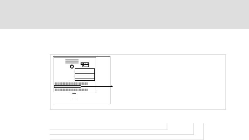
3.4Connections and interfaces
EMF2133IB
OFF ON
|
|
|
8 |
|
2131 |
|
|
|
|
|
|
|
|||
|
|
|
7 |
|
64 |
|
|
|
|
|
6 |
|
32 |
Adresse |
|
|
|
|
324 5 |
|
2 |
||
|
|
|
|
|
16 |
|
|
|
|
|
|
|
8 |
|
|
|
|
|
|
|
4 |
|
|
|
|
|
|
|
1 |
|
|
|
|
|
|
||||
|
|
1 |
|
|
|||
|
|
|
|
|
|
|
|
|
|
|
24V DC |
||||
|
|
|
|
||||
|
|
|
|
+ |
_ |
|
|
|
|
|
|
|
|
||
|
|
|
|
|
|
|
|
L
PROFIBUS DP
2133
|
2133PFB003 |
2102LEC007 |
|
Fig. 3−1 |
EMF2133IB communication module (PROFIBUS−DP) |
|
|
|
|
|
|
Pos. |
Description |
Detailed |
|
|
|
information |
|
|
|
|
|
0Status of the voltage supply (green LED)
1 |
Status of the PROFIBUS communication (yellow LED) |
^ 112 |
2Operating status of the standard device (red/green LED)
3 |
DIP switches for setting the ... |
|
|
l Compatibility with the PROFIBUS communication module EMF2131IB |
^ 37 |
|
l Station address |
^ 42 |
|
|
|
4 |
PROFIBUS connection (Sub−D socket, 9−pole) |
^ 24 |
|
|
^ 27 |
|
|
|
5 |
Connection for external voltage supply |
^ 29 |
|
(Plug connector with screw connection, 2−pole) |
|
|
|
|
|
|
|
7 |
PE connection (only with 82XX) |
|
|
|
|
6 |
Fixing screw |
|
|
|
|
8 |
Nameplate |
^ 13 |
)Note!
Only for 820X and 821X:
If required, use an additional PE shield cable which avoids EMC−related communication interference in surroundings with extreme disturbances.
EDSMF2133IB EN 5.0
l |
15 |

4Technical data
General data
4Technical data
4.1 |
General data |
|
|
|
|
|
|
|
|
|
Area |
Values |
|
|
|
Order designation |
EMF2133IB |
|
|
|
|
|
|
|
|
PNO ID number |
2133hex |
|
|
|
Communication profile |
l |
PROFIBUS−DP−V0 |
|
|
(DIN 19245 Part 1 and Part 3) |
l |
PROFIBUS−DP−V1 |
|
|
|
|
|
|
|
Communication medium |
RS485 |
|
|
|
|
|
|
|
|
Interface |
9−pin Sub−D socket |
|
|
|
|
|
|
|
|
Drive profile |
l DRIVECOM profile "drive technology 20" (can be switched off) |
|
|
|
|
l PROFIdrive profile (can be switched off, state machine and PROFIdrive |
|
|
|
|
|
parameter data channel) |
|
|
|
|
|
|
|
Network topology |
l |
without repeaters: Line |
|
|
|
l with repeaters: Line or tree |
|
|
|
|
|
|
|
|
PROFIBUS nodes |
Slave |
|
|
|
|
|
|
|
|
Baud rate [kbps] |
9.6 ... 12000 (automatic detection) |
|
|
|
|
|
|
|
|
Process data words |
1 ... 12 words |
|
|
|
|
(16 bits/word) |
|
|
|
|
|
|
|
|
DP user data length |
1 ... 12 process data words + |
|
|
|
|
4 parameter data words |
|
|
|
|
|
|
|
|
Max. number of stations |
l Standard: 32 (= 1 bus segment) |
|
|
|
|
l |
with repeater: 125 |
|
|
|
|
|
|
|
Max. cable length per bus |
1200 m (depending on the baud rate and cable type used) |
|
|
|
segment |
|
|
|
|
|
|
|
|
|
External DC voltage supply |
V = +24 V DC ±10 % |
|
|
|
|
I = 120 mA |
|
|
,Documentation for Lenze series of devices 8200 vector, 9300 and ECS
Here you can find the ambient conditions and the electromagnetic compatibility (EMC) specifications applying to the communication module.
16 |
l |
EDSMF2133IB EN 5.0

Technical data |
4 |
Protective insulation
4.2Protective insulation
{Danger!
Dangerous electrical voltage
If Lenze controllers are used on a phase earthed mains with a rated mains voltage ³ 400 V, protection against accidental contact is not ensured without implementing external measures.
Possible consequences:
ƒDeath or serious injury
Protective measures:
ƒIf protection against accidental contact is required for the control terminals of the controller and the connections of the plugged device modules, ...
–a double isolating distance must exist.
–the components to be connected must be provided with the second isolating distance.
Insulation between bus and ... |
Type of insulation (in accordance with EN |
|
|
|
|
61800−5−1) |
|
l Reference earth / PE |
Functional insulation |
|
|
l |
External supply |
Functional insulation |
|
|
|
|
|
l |
Power section |
|
|
|
– 820X / 821X |
Basic insulation |
|
|
– 822X / 8200 vector |
Reinforced insulation |
|
|
– Drive PLC |
Reinforced insulation |
|
|
– 93XX / 9300 Servo PLC |
Reinforced insulation |
|
|
– ECS servo system |
Reinforced insulation |
|
|
|
|
|
l |
Control terminals |
|
|
|
– 820X / 8200 vector |
Functional insulation |
|
|
– 821X |
Functional insulation |
|
|
– 822X |
Basic insulation |
|
|
– Drive PLC |
Basic insulation |
|
|
– 93XX / 9300 Servo PLC |
Basic insulation |
|
|
– ECS servo system |
Reinforced insulation |
|
EDSMF2133IB EN 5.0
l |
17 |

4Technical data
Communication time
Processing time 820X
4.3Communication time
The communication time is the time between the start of a request and the arrival of the corresponding response.
The communication times depend on ...
ƒthe processing time in the controller
ƒthe transmission delay time
–the baud rate
–the telegram length
4.3.1Processing time 820X
For the 820X series several processing steps are required in the controller, which are processed cyclically.
A processing cycle consists of:
ƒWriting of control word or setpoint if the value has changed;
ƒAlternating reading of status word and actual value;
ƒProcessing of parameter accesses if there is a job.
If the processing time caused by cyclic reading of the status word/actual value is too large, the alternating reading of status word and actual value can be suppressed. This is controlled by bit 15 (process input data inhibit) of the DRIVECOM control word:
ƒProcess input data inhibit = 0: Status and actual value update active
ƒProcess input data inhibit = 1: Status and actual value update not active
A suppression of the processing of parameter accesses is not necessary, since this is controlled by the user.
In the following table the times for the processing steps are listed:
Processing step |
Max. processing time in [ms] |
|
|
|
|
|
Process input data |
Tolerance |
Process input data |
Tolerance |
|
|
inhibit = 0 |
|
inhibit = 1 |
|
|
|
|
|
|
|
|
Read parameter |
55 |
+48 |
55 |
+8 |
|
|
|
|
|
|
|
Control word or setpoint |
27 |
+48 |
27 |
+8 |
|
|
|
|
|
|
|
Control word and |
54 |
+56 |
54 |
+16 |
|
setpoint |
|
|
|
|
|
|
|
|
|
|
|
Write parameter |
108 |
+32 |
− |
− |
|
|
|
|
|
|
|
Status word and actual |
200 |
+40 |
200 |
− |
|
value |
|
|
|
|
|
)Note!
A setpoint sign reversal also results in writing the control word.
18 |
l |
EDSMF2133IB EN 5.0

Technical data |
4 |
Communication time
Processing time 821X / 822X / 824X / 8200 vector
4.3.2Processing time 821X / 822X / 824X / 8200 vector
Parameter data |
Process data |
|
30 ... 50 ms |
2 ... 3 ms |
|
4.3.3Processing time 93XX / ECSxS
There are no interdependencies between parameter data and process data.
Parameter data |
Process data |
|
Approx. 30 ms + 20 ms tolerance (typical) |
2 ms + 1 ms tolerance |
|
For some codes, the processing time can be longer (see |
|
|
documentation for 9300 and ECS servo system). |
|
|
4.3.4Processing time Drive PLC / 9300 Servo PLC / ECSxA
Parameter data |
Process data |
|
Approx. 30 ms + 20 ms tolerance (typical) |
Depending on the process image |
|
For some codes, the processing time can be longer (see |
|
|
documentation for 9300 and ECS servo system). |
|
|
EDSMF2133IB EN 5.0
l |
19 |
4Technical data
Dimensions
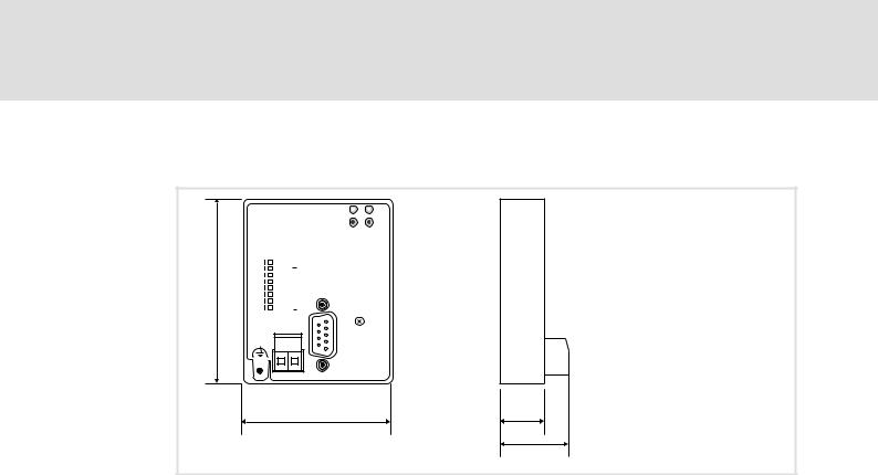
4.4Dimensions
OFF |
ON |
||
b |
|
|
|
|
|
8 |
|
|
|
|
|
|
|
7 |
|
|
|
|
|
|
|
6 |
|
|
|
|
|
|
|
5 |
|
|
|
|
|
|
|
3 4 |
|
|
|
||
|
|
|
|
|
|
|
2 |
|
|
|
|
|
|
|
1 |
|
|
|
|
L
PROFIBUS DP
2131 |
|
64 |
|
32 |
Adresse |
16 |
|
8 |
|
4 |
|
2 |
|
1 |
|
24V DC
+ _
|
2133 |
|
a |
18 |
e1 |
|
|
e
2133PFB003
a |
61 mm |
b |
75 mm |
e |
28 mm |
e1 |
18 mm |
20 |
l |
EDSMF2133IB EN 5.0
Installation 5
5Installation
}Danger!
Inappropriate handling of the communication module and the standard device can cause serious personal injury and material damage.
Observe the safety instructions and residual hazards described in the documentation for the standard device.
(Stop!
Electrostatic discharge
Electronic components of the communication module can be damaged or destroyed through electrostatic discharge.
Possible consequences:
ƒThe communication module is damaged.
ƒFieldbus communication is not possible or faulty.
Protective measures
ƒDischarge electrostatic charges before touching the module.
EDSMF2133IB EN 5.0
l |
21 |
5Installation
Mechanical installation
5.1Mechanical installation
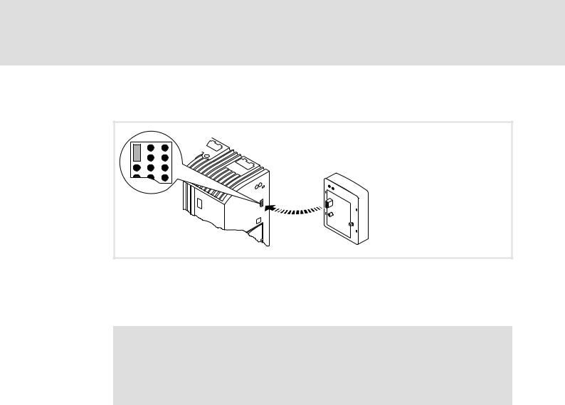
2102LEC014
Fig. 5−1 Attaching the communication module
ƒPlug the communication module onto the standard device (here: 8200 vector).
ƒTighten the communication module to the standard device using the fixing screw in order to ensure a good PE connection.
)Note!
For the internal supply of the communication module by the 8200 vector frequency inverter the jumper has to be adjusted within the interface opening (see illustration above).
Observe the notes (¶ 28).
22 |
l |
EDSMF2133IB EN 5.0

Installation 5
Electrical installation
Wiring according to EMC (CE−typical drive system)
5.2Electrical installation
5.2.1Wiring according to EMC (CE−typical drive system)
For wiring according to EMC requirements observe the following points:
)Note!
ƒSeparate control cables/data lines from motor cables.
ƒConnect the shields of control cables/data lines at both ends in the case of digital signals.
ƒUse an equalizing conductor with a cross−section of at least 16 mm2 (reference: PE) to avoid potential differences between the bus nodes.
ƒObserve the other notes concerning EMC−compliant wiring given in the documentation for the standard device.
Wiring procedure
1.Comply with bus topology, thus do not use stubs.
2.Observe notes and wiring instructions in the documents for the control system.
3.Only use cables that comply with the given specifications (¶ 25).
4.Observe notes for the voltage supply of the module (¶ 28).
5.Activate the bus terminating resistors on the first and last physical bus device (¶ 24).
6.Adapt baud rate to the bus cable length.
EDSMF2133IB EN 5.0
l |
23 |
5Installation
Electrical installation
Wiring with a host (master)
5.2.2Wiring with a host (master)
{Danger!
You have to provide additional electrical isolation if ...
ƒan 820X and 821X controller is connected to the host and
ƒa safe electrical isolation (reinforced insulation) according to EN 61800−5−1 is required.
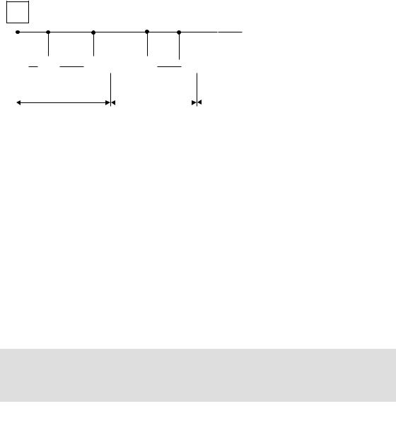
Basic wiring of the PROFIBUS
The connection of the PROFIBUS bus system is shown in the general layout drawing.
1
|
|
|
|
|
|
|
|
|
|
|
|
|
|
|
|
|
|
|
|
|
|
|
|
|
|
|
|
|
|
|
|
|
|
|
|
|
|
|
|
|
|
|
|
|
|
|
|
|
|
|
|
|
|
|
|
|
|
|
|
|
|
|
|
|
|
|
|
|
|
|
|
|
|
|
|
|
|
|
|
|
|
|
|
|
|
|
|
|
|
|
|
|
|
|
|
|
|
|
|
|
|
|
|
|
|
|
|
|
|
|
|
|
|
|
|
|
|
|
|
|
|
|
|
|
|
|
|
|
|
|
|
|
|
|
|
|
|
|
|
|
|
|
|
|
|
|
|
|
|
|
|
|
|
|
|
|
|
|
|
|
|
|
|
|
|
|
|
|
|
|
|
|
|
|
|
|
|
|
|
|
|
|
|
|
|
|
|
|
|
|
|
|
|
|
|
|
|
|
|
|
|
|
|
|
|
|
|
|
|
|
|
|
|
|
|
|
|
|
|
|
|
|
|
|
|
|
|
|
|
|
|
|
|
|
|
|
|
|
|
|
|
|
|
|
|
|
|
|
|
|
|
|
|
|
|
|
|
|
|
|
|
|
|
|
|
|
|
|
|
|
|
|
|
|
|
|
|
|
|
|
|
|
|
|
|
|
|
|
|
|
|
|
|
|
|
|
|
|
|
|
|
|
|
|
|
|
|
|
|
|
|
|
|
|
|
|
|
|
|
|
|
|
|
|
|
|
|
|
|
|
|
|
|
|
|
|
|
|
|
|
|
|
|
|
|
|
|
|
|
|
|
|
|
|
|
|
|
|
|
|
|
|
|
|
|
|
|
|
|
|
|
|
|
|
|
|
|
|
|
|
|
|
|
|
|
|
|
|
|
3 |
|
|
|
|
|
|
|
|
|
3 |
|
|
3 |
|
|
|
|
||
|
|
|
|
|
|
|
|
|
|
|
|
|
|
|
|
|
|
|
|
|
|
|
|
GG + 2133 |
|
|
|
GG + 2133 |
|
GG + 2133 |
|
|
|
|
||||||
|
|
|
|
|
|
|
|
|
|
|
|
|
|
|
|
|
|
|
|
|
|
|
|
|
|
|
|
|
|
|
|
|
|
|
|
|
|
|
|
|
|
|
|
|
|
2 |
|
|
|
|
|
|
|
|
|
|
|
|
|
|
|
|
|
|
2 |
|
|
|
2 |
|
|
|
|
|
|||||||
|
|
|
|
|
|
|
|
|
|
|
|
|
|
|
|
|
|
|
|
|
|
|
|
|
|
|
|
|
|
|
|
|
|
|
|
|
|
|
|
|
|
|
|
|
|
|
|
|
|
|
|
|
|
|
|
|
|
|
|
|
|
|
|
|
|
|
|
|
|
|
|
1200 m |
|
|
|
|
|
|
|
||
|
|
|
|
|
|
|
|
|
|
|
|
|
|
|
|
|
|
|
|
|
|
|
|
|
|
|
|
|
|
|
|
|
|
|
|
|
|
|||
|
|
|
|
|
|
|
|
|
|
|
|
|
|
|
|
|
|
|
|
|
|
|
|
|
|
|
|
|
|
0 m |
|
|
|
|
|
|
|
|||
|
|
|
|
|
|
|
|
|
|
|
|
|
|
|
|
|
|
|
|
|
|
|
|
|
|
|
|
|
|
|
|
|
|
|
|
|
|
|
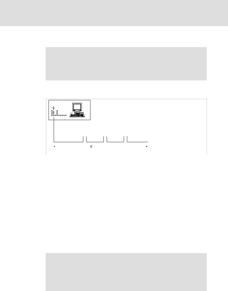
E82ZAFP005 |
|
Fig. 5−2 |
|
|
|
|
|
|
Example: PROFIBUS with RS485 wiring (without repeater) |
|||||||||||||||||||||||||||||||||
|
|
|
|
|
|
|
|
|
|
|
|
|
|
|
|
|
|
|
|
|
|
|
|
|||||||||||||||||
No. |
|
|
Element |
|
|
Comment |
|
|
|
|
|
|
||||||||||||||||||||||||||||
1 |
|
|
|
|
|
|
Host |
|
|
e.g. PC or PLC with PROFIBUS master interface module |
||||||||||||||||||||||||||||||
|
|
|
|
|
|
|
|
|
|
|
|
|
|
|
|
|
|
|
|
|
|
|
||||||||||||||||||
2 |
|
|
|
|
|
|
Bus cable |
|
|
Connects the PROFIBUS master interface module to the communication |
||||||||||||||||||||||||||||||
|
|
|
|
|
|
|
|
|
|
|
|
|
|
|
|
|
|
|
|
|
|
|
|
|
|
|
|
|
|
|
|
modules. |
|
|
|
|
|
|
||
|
|
|
|
|
|
|
|
|
|
|
|
|
|
|
|
|
|
|
|
|
|
|
|
|
|
|
|
|
|
|
|
l The baud rate depends on the bus cable length (^ 26). |
||||||||
|
|
|
|
|
|
|
|
|
|
|
|
|
|
|
|
|
|
|
|
|
|
|
||||||||||||||||||
3 |
|
|
|
|
|
|
PROFIBUS slave |
|
|
Applicable standard device (GG, ^ 12) with communication module |
||||||||||||||||||||||||||||||
|
|
|
|
|
|
|
|
|
|
|
|
|
|
|
|
|
|
|
|
|
|
|
|
|
|
|
|
|
|
|
|
l Activate the bus terminating resistors on the first and last physical bus |
||||||||
|
|
|
|
|
|
|
|
|
|
|
|
|
|
|
|
|
|
|
|
|
|
|
|
|
|
|
|
|
|
|
|
|
device (^ 24). |
|||||||
|
|
|
|
|
|
|
|
|
|
|
|
|
|
|
|
|
|
|
|
|
|
|
||||||||||||||||||
) Note! |
|
|
|
|
|
|
|
|
|
|
|
|||||||||||||||||||||||||||||
|
|
|
|
|
|
|
|
When using a repeater, max. 125 devices can communicate via the PROFIBUS. |
|
|||||||||||||||||||||||||||||||
|
|
|
|
|
|
|
|
|
|
|
|
|
|
|
|
|
|
|
|
|
|
|
|
|
|
|
|
|
|
|
|
|
|
|
|
|
|
|
|
|
Bus terminating resistor
The PROFIBUS must be terminated by a bus terminating resistor at the physically first and last station.
The bus terminating resistor is in the bus connector (¶ 128)and is activated using a switch.
)Note!
ƒIf you want to disconnect individual bus devices, ensure that the bus terminators at the cable ends remain active.
ƒPlease note that the bus termination is no longer active if ...
–the connector has been disconnected e.g. in service case;
–the voltage supply of the communication module has been switched off.
24 |
l |
EDSMF2133IB EN 5.0
|
|
|
|
|
|
|
|
|
|
|
|
|
|
|
|
|
|
|
|
Installation |
5 |
|
|
|
|
|
|
|
|
|
|
|
|
|
|
|
|
|
|
|
|
|
Electrical installation |
|
|
||
|
|
|
|
|
|
|
|
|
|
|
|
|
|
|
|
|
Wiring with a host (master) |
|
|
||||
|
Number of bus devices |
|
|
|
|
|
|
|
|
|
|
|
|
|
|||||||||
|
|
|
|
|
|
|
|
|
|
|
|
|
|
|
|
|
|
|
|
|
|
||
|
|
M |
|
|
|
|
|
|
|
|
|
|
|
|
|
|
|
|
|
|
|
||
|
|
|
|
|
|
|
|
|
|
|
|
|
|
|
|
|
|
|
|
|
|
|
|
|
|
|
|
|
|
|
|
|
|
R |
|
|
|
|
|
|
R |
|
|
|
|
|
|
|
|
|
|
|
|
|
|
|
|
|
|
|
|
|
|
|
|
|
|
|
|
||
|
|
|
|
|
|
|
|
|
|
|
|
|
|
|
|
|
|
|
|
|
|
|
|
|
|
S |
|
S |
|
|
S |
|
|
S |
|
S |
|
|
|
|
|
|
|
|
|||
|
|
|
|
|
|
|
|
|
|
|
|
|
|
|
|
|
|
|
|
|
|
||
|
|
|
|
|
|
1 |
|
|
|
2 |
3 |
|
|
|
|
|
|||||||
|
|
|
|
|
|
|
|
|
|
|
|
|
|
|
|
|
|
|
|
|
|
2133PFB004 |
|
|
|
|
|
|
|
|
|
|
|
|
|
|
|
|
|
|
|
||||||
|
|
|
|
|
|
|
|
|
|
|
|
|
|
|
|
|
|
||||||
|
Segment |
|
|
|
Master (M) |
|
|
|
|
|
|
Slave (S) |
|
|
Repeater (R) |
|
|
||||||
1 |
|
|
|
|
1 |
|
|
|
31 |
|
|
− |
|
|
|||||||||
|
|
|
|
|
|
2 |
|
|
|
30 |
|
|
− |
|
|
||||||||
|
|
|
|
|
|
|
|
|
|
|
|
|
|
|
|
|
|||||||
2 |
|
|
|
|
|
|
|
− |
|
|
30 |
|
1 |
|
|
||||||||
|
|
|
|
|
|
|
|
|
|
|
|
|
|
|
|
|
|||||||
|
3 |
|
|
|
|
|
|
|
− |
|
|
30 |
|
|
1 |
|
|
||||||
I Tip!
Repeaters do not have a device address. When calculating the maximum number of bus devices, they reduce the number of devices by 1 on each side of the segment.
Repeaters can be used to build up line and tree topologies. The maximum total bus system expansion depends on ...
ƒthe baud rate used;
ƒthe number of repeaters used.
Specification of the transmission cable
)Note!
Only use cables complying with the listed specifications of the PROFIBUS user organisation.
Field |
Values |
|
Specific resistance |
135 ... 165 W/km, (f = 3 ... 20 MHz) |
|
|
|
|
Capacitance per unit length |
£ 30 nF/km |
|
|
|
|
Loop resistance |
< 110 W/km |
|
|
|
|
Core diameter |
> 0.64 mm |
|
|
|
|
Core cross−section |
> 0.34 mm2 |
|
Cores |
Twisted double, insulated and shielded |
|
EDSMF2133IB EN 5.0
l |
25 |

5Installation
Electrical installation
Wiring with a host (master)
Bus cable length
The length of the bus cable depends on the baud rate used:
Baud rate [kbps] |
Length [m] |
|
9.6 ... 93.75 |
1200 |
|
|
|
|
187.5 |
1000 |
|
|
|
|
500 |
400 |
|
|
|
|
1500 |
200 |
|
|
|
|
3000 ... 12000 |
100 |
|
)Note!
The baud rate depending on the data volume, cycle time, and number of nodes should only be selected as high as required for the application.
I Tip!
For high baud rates we recommend to consider the use of optical fibres.
Advantages of optical fibres:
ƒOn the transmission path external electromagnetic interference remains ineffective.
ƒBus lengths of several kilometres are also possible with higher baud rates. The bus length
–is irrespective of the baud rate.
–depends on the optical fibre used.
26 |
l |
EDSMF2133IB EN 5.0

Installation 5
Electrical installation
Connection of the PROFIBUS
5.2.3Connection of the PROFIBUS
The PROFIBUS network is connected via the 9−pole Sub−D socket.
View |
|
Pin |
Designation |
Description |
|
|
1 |
− |
− |
|
|
2 |
− |
− |
9 |
5 |
3 |
RxD/TxD−P |
Data cable B (receive / send data plus) |
|
4 |
RTS |
Request To Send |
|
|
|
|||
|
|
|
|
(receive / send data, no differential signal) |
|
|
5 |
M5V2 |
Data reference potential (ground to 5V) |
|
|
6 |
P5V2 |
5 V DC / 30 mA (bus termination) |
6 |
1 |
7 |
− |
− |
|
|
8 |
RxD/TxD−N |
Data cable A (receive / send data minus) |
|
|
9 |
− |
− |
EDSMF2133IB EN 5.0
l |
27 |
5Installation
Electrical installation
Voltage supply
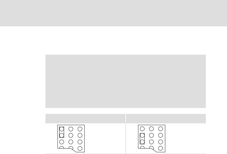
5.2.4Voltage supply Internal voltage supply
)Note!
Internal voltage supply has been selected in the case of standard devices with an extended AIF interface opening (e.g. front of 8200 vector). The area shown on a grey background in the graphic marks the jumper position.
ƒBy default, this is not supplied internally in the standard device.
ƒFor internal voltage supply place the jumper on the position indicated below.
In the case of all other device series (9300, ECS), voltage is always supplied from the standard device.
Lenze setting |
Internal voltage supply |
(Only external voltage supply possible.)
28 |
|
l |
|
|
|
||
|
|
||
|
|
EDSMF2133IB EN 5.0

Installation 5
Electrical installation
Voltage supply
External voltage supply
)Note!
Always use a separate power supply unit in every control cabinet and safely separate it according to EN 61800−5−1 ("SELV"/"PELV") in the case of external voltage supply and larger distances between the control cabinets.
External voltage supply of the communication module is required if communication via the fieldbus is to be maintained even when the power supply of the standard device fails.
)Note!
With external voltage supply of the communication module, the active bus terminating resistor is fed independently of the operation of the basic device. Thus the bus system remains active even if the basic device is switched off or fails.
Plug connector |
Explanation |
|
"+" |
V = 24 V DC (21.6 V − 0% ... 26.4 V + 0 %) |
|
|
I = 120 mA |
|
|
|
|
"−" |
Reference potential for external voltage supply |
|
|
|
|
Controller |
External voltage supply |
|
820X |
Always required |
|
|
|
|
821X / 822X / 824X / |
Only required if the mains supplying the corresponding controller is to be switched off |
|
93XX / 9300 Servo PLC / |
but communication must not be interrupted. |
|
Drive PLC / ECSxS / |
For these basic devices the internal voltage supply can be used. |
|
ECSxP / ECSxA |
|
|
|
|
|
8200 vector |
See notes given in "Internal voltage supply" ^ 28 |
|
EDSMF2133IB EN 5.0
l |
29 |

5Installation
Electrical installation
Cable cross−sections and screw−tightening torques
5.2.5Cable cross−sections and screw−tightening torques
Area |
Values |
Electrical connection |
Plug connector with screw connection |
Possible connections |
rigid: |
|
1.5 mm2 (AWG 16) |
|
flexible: |
|
without wire end ferrule |
|
1.5 mm2 (AWG 16) |
|
with wire end ferrule, without plastic sleeve |
|
1.5 mm2 (AWG 16) |
|
with wire end ferrule, with plastic sleeve |
|
1.5 mm2 (AWG 16) |
Tightening torque |
0.5 ... 0.6 Nm (4.4 ... 5.3 lb−in) |
Stripping length |
6 mm |
30 |
l |
EDSMF2133IB EN 5.0
Loading...