


 Loading...
Software Manual
Cam Designer Basic
L
This Manual is valid for the Cam Designer Basic from version 2.3
Copyright
© 2005 Lenze Drive Systems GmbH. All rights reserved.
Imprint
Lenze Drive Systems GmbH
POB 10 13 52, 31763 Hameln, Germany
Phone: ++49 (0)5154 / 82-0
Fax: ++49 (0)5154 / 82-2111
E-mail: Lenze@Lenze.de
Copyright information
All texts, photos and graphics contained in this documentation are subject to copyright protection. No part of this documentation may be copied or made available to third parties without the explicit written approval of Lenze Drive Systems GmbH.
Liability
All information given in this documentation has been selected carefully and tested for compliance with the described hardware and software. Nevertheless, discrepancies cannot be ruled out. We do not accept any responsibility or liability for any damage that may occur. Required corrections will be included in updates of this documentation.
Trademarks
Microsoft, Windows and Windows NT are either registered trademarks or trademarks of Microsoft Corporation in the U.S.A. and/or other countries.
Adobe and Reader are either registered trademarks or trademarks of Adobe Systems Incorporated in the U.S.A.and/or other countries.
All other product names contained in this documentation are trademarks of the corresponding owners.
2 |
Version 2.1 EN - 09/2005 - TD16 |
L

Cam Designer Basic
Contents
Contents
1 |
About this Manual . . . . . . . . . . . . . . . . . . . . . . . . . . . . . . . . . . . . . . . . . . . . . . . . . . . . . |
5 |
||
|
1.1 |
Conventions used . . . . . . . . . . . . . . . . . . . . . . . . . . . . . . . . . . . . . . . . . . . . . . . . . . . |
5 |
|
|
1.2 |
Layout of the safety information . . . . . . . . . . . . . . . . . . . . . . . . . . . . . . . . . . . . . |
6 |
|
2 |
System requirements . . . . . . . . . . . . . . . . . . . . . . . . . . . . . . . . . . . . . . . . . . . . . . . . . . . |
7 |
||
|
2.1 |
Connection with the target system . . . . . . . . . . . . . . . . . . . . . . . . . . . . . . . . . . . |
7 |
|
3 |
Software installation . . . . . . . . . . . . . . . . . . . . . . . . . . . . . . . . . . . . . . . . . . . . . . . . . . . |
8 |
||
4 |
Introduction . |
. . . . . . . . . . . . . . . . . . . . . . . . . . . . . . . . . . . . . . . . . . . . . . . . . . . . . . . . . . |
9 |
|
|
4.1 |
Motion tasks . . . . . . . . . . . . . . . . . . . . . . . . . . . . . . . . . . . . . . . . . . . . . . . . . . . . . . . . |
12 |
|
|
4.2 |
Scaled motion rules. . . . . . . . . . . . . . . . . . . . . . . . . . . . . . . . . . . . . . . . . . . . . . . . . . |
13 |
|
5 |
User interface. . . . . . . . . . . . . . . . . . . . . . . . . . . . . . . . . . . . . . . . . . . . . . . . . . . . . . . . . . |
14 |
||
|
5.1 |
Using the direct help. . . . . . . . . . . . . . . . . . . . . . . . . . . . . . . . . . . . . . . . . . . . . . . . . |
14 |
|
|
5.2 |
Language selection . . . . . . . . . . . . . . . . . . . . . . . . . . . . . . . . . . . . . . . . . . . . . . . . . . |
15 |
|
|
5.3 |
Title bar . . . . . . . . . . . . . . . . . . . . . . . . . . . . . . . . . . . . . . . . . . . . . . . . . . . . . . . . . . . . . |
15 |
|
|
5.4 |
Menu bar . . . . . . . . . . . . . . . . . . . . . . . . . . . . . . . . . . . . . . . . . . . . . . . . . . . . . . . . . . . |
15 |
|
|
5.5 |
Toolbar |
. . . . . . . . . . . . . . . . . . . . . . . . . . . . . . . . . . . . . . . . . . . . . . . . . . . . . . . . . . . . . |
16 |
|
5.6 |
Project structure. . . . . . . . . . . . . . . . . . . . . . . . . . . . . . . . . . . . . . . . . . . . . . . . . . . . . |
17 |
|
|
5.7 |
Screen divider . . . . . . . . . . . . . . . . . . . . . . . . . . . . . . . . . . . . . . . . . . . . . . . . . . . . . . . |
18 |
|
|
5.8 |
Workspace . . . . . . . . . . . . . . . . . . . . . . . . . . . . . . . . . . . . . . . . . . . . . . . . . . . . . . . . . . |
18 |
|
|
5.9 |
Output area . . . . . . . . . . . . . . . . . . . . . . . . . . . . . . . . . . . . . . . . . . . . . . . . . . . . . . . . . |
18 |
|
|
5.10 |
Status bar . . . . . . . . . . . . . . . . . . . . . . . . . . . . . . . . . . . . . . . . . . . . . . . . . . . . . . . . . . . |
19 |
|
|
5.11 |
Document window (worksheet) . . . . . . . . . . . . . . . . . . . . . . . . . . . . . . . . . . . . . . |
20 |
|
6 |
Operation . . . |
. . . . . . . . . . . . . . . . . . . . . . . . . . . . . . . . . . . . . . . . . . . . . . . . . . . . . . . . . . |
21 |
|
|
6.1 |
Create a new project . . . . . . . . . . . . . . . . . . . . . . . . . . . . . . . . . . . . . . . . . . . . . . . . |
22 |
|
|
|
6.1.1 Step 1: Defining the features of the master axes . . . . . . . . . . . . . . . |
22 |
|
|
|
6.1.2 Step 2: Defining the properties of the slave axis . . . . . . . . . . . . . . . |
24 |
|
|
|
6.1.3 Step 3: Set profile options . . . . . . . . . . . . . . . . . . . . . . . . . . . . . . . . . . . . |
27 |
|
|
|
6.1.4 Step 4: Defining the file name and directory for a project. . . . . . . |
29 |
|
|
|
6.1.5 Step 5: Adding a slave axis. . . . . . . . . . . . . . . . . . . . . . . . . . . . . . . . . . . . |
29 |
|
|
|
6.1.6 |
Creating further products . . . . . . . . . . . . . . . . . . . . . . . . . . . . . . . . . . . . |
32 |
|
6.2 |
Open an existing project . . . . . . . . . . . . . . . . . . . . . . . . . . . . . . . . . . . . . . . . . . . . . |
34 |
|
|
|
6.2.1 Selecting the properties of a slave. . . . . . . . . . . . . . . . . . . . . . . . . . . . . |
34 |
|
|
|
6.2.2 |
Deleting a slave . . . . . . . . . . . . . . . . . . . . . . . . . . . . . . . . . . . . . . . . . . . . . . |
35 |
|
6.3 |
Connection with the OPC server . . . . . . . . . . . . . . . . . . . . . . . . . . . . . . . . . . . . . . |
36 |
|
|
6.4 |
Downloading the drive data. . . . . . . . . . . . . . . . . . . . . . . . . . . . . . . . . . . . . . . . . . |
36 |
|
L
2.1 EN - 09/2005 |
3 |

Cam Designer Basic
Contents
|
6.5 |
Saving the project . . . . . . . . . . . . . . . . . . . . . . . . . . . . . . . . . . . . . . . . . . . . . . . . . . . |
37 |
|
6.6 |
Saving a project under another name . . . . . . . . . . . . . . . . . . . . . . . . . . . . . . . . . |
37 |
|
6.7 |
Exiting Cam Designer Basic. . . . . . . . . . . . . . . . . . . . . . . . . . . . . . . . . . . . . . . . . . . |
38 |
7 |
Functions. . . . . . . . . . . . . . . . . . . . . . . . . . . . . . . . . . . . . . . . . . . . . . . . . . . . . . . . . . . . . . |
39 |
|
|
7.1 |
Working with the worksheet . . . . . . . . . . . . . . . . . . . . . . . . . . . . . . . . . . . . . . . . . |
39 |
|
7.2 |
Settings for the worksheet . . . . . . . . . . . . . . . . . . . . . . . . . . . . . . . . . . . . . . . . . . . |
39 |
|
7.3 |
Object Input Mode. . . . . . . . . . . . . . . . . . . . . . . . . . . . . . . . . . . . . . . . . . . . . . . . . . . |
39 |
|
7.4 |
Interpolation mode . . . . . . . . . . . . . . . . . . . . . . . . . . . . . . . . . . . . . . . . . . . . . . . . . . |
40 |
|
7.5 |
Worksteps required for a new cam . . . . . . . . . . . . . . . . . . . . . . . . . . . . . . . . . . . |
40 |
|
7.6 |
Settings of the worksheet . . . . . . . . . . . . . . . . . . . . . . . . . . . . . . . . . . . . . . . . . . . . |
41 |
|
7.7 |
Creation of profiles . . . . . . . . . . . . . . . . . . . . . . . . . . . . . . . . . . . . . . . . . . . . . . . . . . |
41 |
|
7.8 |
Closed profile . . . . . . . . . . . . . . . . . . . . . . . . . . . . . . . . . . . . . . . . . . . . . . . . . . . . . . . |
43 |
|
7.9 |
The cam group . . . . . . . . . . . . . . . . . . . . . . . . . . . . . . . . . . . . . . . . . . . . . . . . . . . . . . |
46 |
|
|
7.9.1 Defining the cam type and cam reference . . . . . . . . . . . . . . . . . . . . . |
46 |
|
|
7.9.2 Cam types . . . . . . . . . . . . . . . . . . . . . . . . . . . . . . . . . . . . . . . . . . . . . . . . . . . |
47 |
|
7.10 |
Export of profile data . . . . . . . . . . . . . . . . . . . . . . . . . . . . . . . . . . . . . . . . . . . . . . . . |
48 |
|
7.11 |
Cam Designer Basic Online Download . . . . . . . . . . . . . . . . . . . . . . . . . . . . . . . . |
49 |
8 |
Appendix. . . . . . . . . . . . . . . . . . . . . . . . . . . . . . . . . . . . . . . . . . . . . . . . . . . . . . . . . . . . . . |
50 |
|
|
8.1 |
Error numbers, causes & remedies. . . . . . . . . . . . . . . . . . . . . . . . . . . . . . . . . . . . |
50 |
|
8.2 |
Glossary. . . . . . . . . . . . . . . . . . . . . . . . . . . . . . . . . . . . . . . . . . . . . . . . . . . . . . . . . . . . . |
51 |
9 |
Index |
. . . . . . . . . . . . . . . . . . . . . . . . . . . . . . . . . . . . . . . . . . . . . . . . . . . . . . . . . . . . . . . . . |
53 |
4 |
2.1 EN - 09/2005 |
L

Cam Designer Basic
About this Manual
Conventions used
1 |
About this Manual |
This Manual contains information about Lenze Cam Designer Basic.
The »Cam Designer Basic« is a software which is used to transfer recipes consisting of motion profiles, cam tracks and position markers from a PC to Lenze target systems.
Special features of the »Cam Designer Basic« are:
Import of CAD data via standardised interfaces (VDI 2143).
Program operation via an easy-to-use PC user interface for the first commissioning and the preparation of additional functions to be provided to the final user by the mechanical engineer.
Smoothing of imported CAD data (motion profiles) for a smoother running of the drives.
1.1Conventions used
This Manual uses the following conventions to distinguish between different types of information:
Type of information |
Marking |
Examples/notes |
Variable identifier |
italic |
Set bEnable to TRUE to... |
|
|
|
Window |
|
The message window... / The Options dialog box... |
|
|
|
Control element |
bold |
The OK button... / The Copy command... / The Properties tab... / The |
|
|
Name input field... |
|
|
|
Sequence of menu |
|
If the execution of a function requires several commands, the individual |
commands |
|
commands are separated by an arrow: Select File Open to... |
|
|
|
Keyboard command |
<bold> |
Use <F1> to call the Online Help. |
|
|
|
|
|
If a command requires a combination of keys, a "+" is placed between |
|
|
the key symbols: |
|
|
Use <Shift>+<ESC> to... |
|
|
|
Program listings |
Courier |
IF var1 < var2 THEN |
|
|
|
Keyword |
Courier |
a = a + 1 |
|
bold |
END IF |
|
|
|
|
|
|
Link |
underlined |
Links are highlighted references which are activated by means of a |
|
|
mouse click. |
|
|
|
Safety information |
|
Layout of the safety information ( 6) |
|
|
|
Step-by-step instruc- |
|
Like safety information, step-by-step instructions and tips can be recog- |
tions |
nised by an icon. |
|
|
|
|
Tip |
|
|
|
|
|
|
|
|
L
2.1 EN - 09/2005 |
5 |

Cam Designer Basic
About this Manual
Layout of the safety information
1.2Layout of the safety information
All safety information have a uniform structure:
The icon characterises the type of danger.
The signal word characterises the severity of danger.
The note describes the danger and suggests how to avoid the danger.
Signal word
Note
Icon |
Signal word |
Meaning |
Consequences if disregarded |
|
Danger! |
Impending danger to persons |
Death or severe injuries |
hazardous |
|
|
|
electrical |
|
|
|
voltage |
|
|
|
|
|
|
|
general dan- |
|
|
|
ger |
|
|
|
|
|
|
|
|
Stop! |
Potential damage to material |
Damage to the controller or its environment |
|
|
|
|
|
Note! |
Note |
|
|
|
|
|
6 |
2.1 EN - 09/2005 |
L

Cam Designer Basic
System requirements
Connection with the target system
2 |
System requirements |
The following minimum requirements on hardware and software must be met to use the »Cam Designer Basic«.
Microsoft® Windows® 98, Windows NT® 4.0 (as of Service Pack 5), Windows® 2000 (as of Service Pack 2) or Windows® XP.
64 MByte RAM
128 MByte RAM (Windows® XP/2000)
IBM compatible PC (CPU: Pentium 90 MHz processor or faster)
Super VGA screen
Hard disk with at least 120 MB of free disk space
CD-ROM drive
Mouse (Microsoft-compatible)
2.1Connection with the target system
The communication with the target system (controller, Servo PLC or 9300EK servo cam) requires a fieldbus-specific interface module for the PC and the corresponding fieldbus modules for the target systems to be connected.
For system bus (CAN) communication, Lenze offers the following components as interface module for the PC:
Bus system |
Max. number of target systems |
||
|
PC port |
|
Required hardware components |
System bus (CANopen) |
63 |
|
|
|
|
|
|
|
Parallel |
|
PC system bus adapter 2173 |
|
port |
|
incl. connection cable and voltage-supply adapter |
|
(LPT port) |
|
• for DIN keyboard connection |
|
|
|
(EMF2173IB) |
|
|
|
• for PS/2 keyboard connection |
|
|
|
(EMF2173IBV002) |
|
|
|
• for PS/2 keyboard connection with electrical isolation |
|
|
|
(EMF2173IBV003) |
|
|
|
|
|
USB |
|
PC system bus adapter 2177 |
|
(Universal Serial Bus) |
|
incl. connection cable |
|
|
|
(EMF2177IB) |
|
|
|
|
L
2.1 EN - 09/2005 |
7 |

Cam Designer Basic
Software installation
3Software installation
How to install the »Cam Designer Basic«:
1.Start Windows.
2.Insert the CD-ROM »Cam Designer Basic« into the CD-ROM drive.
•If the auto-start function of the CD-ROM drive is active, the installation program is started automatically and you can proceed with step 5.
3.Select Run ... from the start menu.
4.Enter the letter for your CD-ROM drive followed by ":\setup.exe" (e.g. "e:\setup.exe") in the command line and confirm with OK.
5.Follow the instructions of the installation program.
Note!
Installation under Windows NT/2000/XP requires administrator rights!
8 |
2.1 EN - 09/2005 |
L

Cam Designer Basic
Introduction
4 Introduction
»Cam Designer Basic« is a graphic tool for the easy creation of electronic cams.
»Cam Designer Basic« provides the features of the »Cam Designer Professional« in reduced form.
Main features of the »Cam Designer Basic«
Easy creation of cams by means of graphic objects (e.g. lines, polynomials).
Data is directly input using the physical unit.
Display of speed, acceleration torque and jerk.
Printing of the cam graphics with project information and date.
Main features of the Software Package - Cam
48 profiles can be stored in the PLC
289 base points per profile in the relative data model
116 base points per profile the absolute data model
Increased number of the available base points with reduced number of profiles reserved
48 cam groups can be stored
Three tracks per cam group
Four cams per tracks
Main features of the 9300EK servo cam
8 profiles can be stored in the PLC
256 base points per profile in the relative data model
64 base points per profile the absolute data model
Note!
No names are used for profiles and projects in the documentation. The examples use the names assigned by the system. You can assign names on your own in your system.
The »Cam Designer Basic« is a product of the Software Package - Cam. It manages the relevant data of the machine and also creates projects. However, it lacks the »Cam Manager« and hence the ability of managing several products at the same time.
L
2.1 EN - 09/2005 |
9 |

Cam Designer Basic
Introduction
Entries via the »Cam Designer Basic«
The project
Only one product at a time is available, i.e. only one product at a time can be processed.
–Machine structure
–Names of the axes
The feed constant and gearbox factor of each axis
Scaling of the axes for profile creation
The master axis
–Number of cycles of the machine
The value is a rated value and can maximally amount to 199% during operation.
The slave axes
–Number of profiles to be stored
–Number of base points to be assigned
–Selection of the data model
The product (profiles)
–Product name
–Product number
Note!
No names are used for projects and products. The names given by the »Cam Designer Basic« are continued to be used. You are able to select the names on your own in your project.
10 |
2.1 EN - 09/2005 |
L
Cam Designer Basic
Introduction
Advantages of »Cam Manager«
the »Cam Manager« is not included in the »Cam Designer Basic«.
The management of projects with several products and the corresponding axes using the »Cam Designer Basic« is only possible with a directory structure.
The »Cam Designer Professional« manages the projects using the integrated »Cam Manager«.
The assignment between products and axes is displayed in the »Cam Manager«.
The products and axes are stored and managed automatically in the »Cam Designer Professional«.
The storage and management of the products and axes in the »Cam Designer Basic« are provided by means of the *.LCx-files and *.cam-files
–LC9 for Servo PLC and ECS EA
–LC7 for 9300 EK servo cam
L
2.1 EN - 09/2005 |
11 |
Cam Designer Basic
Introduction
Motion tasks
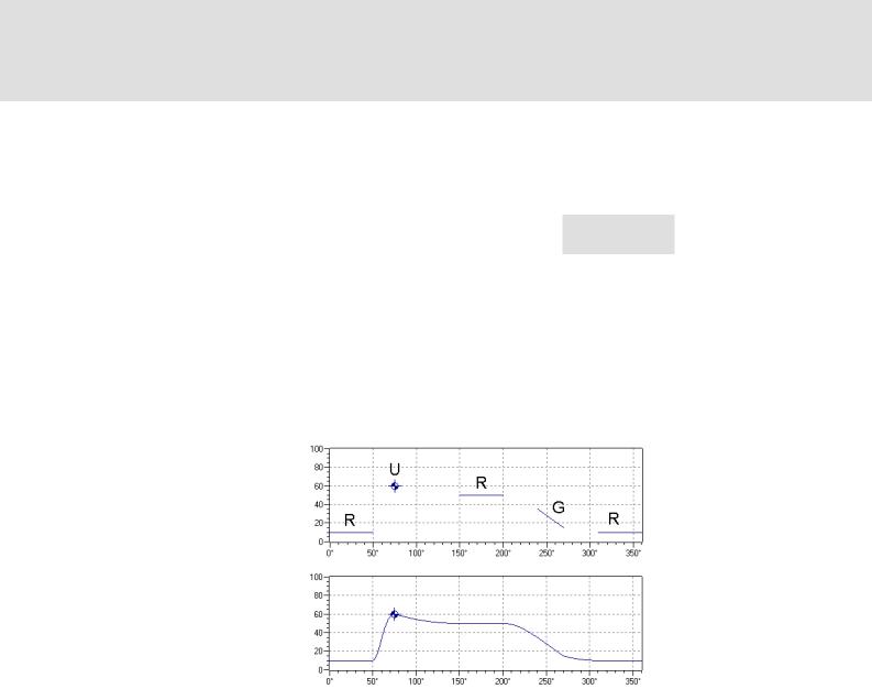
4.1Motion tasks
According to the VDI 2143 with the title "Motion rules for cam mechanisms" the motion tasks can be classified as follows:
Motion task |
Abbreviation |
Speed in the |
Acceleration in the |
Graphical |
|
|
boundary point |
boundary point |
representation |
Break |
R |
v = 0 |
a = 0 |
Line |
|
|
|
|
|
Constant speed |
G |
v ≠ 0 |
a = 0 |
Line |
|
|
|
|
|
Reversal |
U |
v = 0 |
a ≠ 0 |
Point |
|
|
|
|
|
Motion |
B |
v ≠ 0 |
a ≠ 0 |
Point |
|
|
|
|
|
These four motion tasks serve to formulate the technological specifications for all problems relevant to practice.
For calculating the profile segments between the defined sections, the boundary values of the specifications are required.
Since the acceleration for R and G is = 0, these two motion tasks can be described linearly. The boundary values on the left and right connection are identical in this case.
The acceleration for U and B is ≠ 0. These elements can be represented as a point on the worksheet.
After entering these basic elements for the motion tasks and determining the required boundary values, the connections can be entered according to the motion rules. Depending on the connection type used, a jerk-free motion can be achieved.
12 |
2.1 EN - 09/2005 |
L
Cam Designer Basic
Introduction
Scaled motion rules
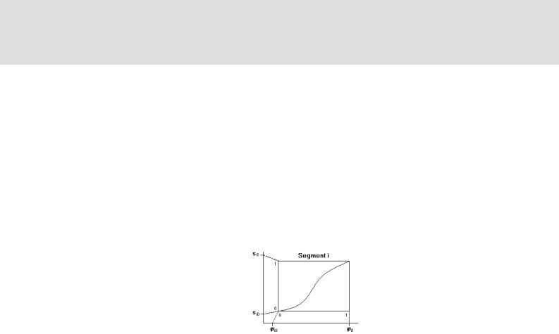
4.2Scaled motion rules
Each segment i of the whole cam describes a part which is defined by the value range si0 = f(ji0) and si1 = f(ji1).
The corresponding functions are imaged internally to the scaled value range of 0...1.
The coefficients of the profiles, included in the property pages, also refer to this scaled value range.
The speeds and accelerations in the property page represent the real boundary value
with regard to the geometrical dimensions. Thus, the calculation is based on the rule v = ds / dj and a = d2s / dj2.
These geometrical values for speed and and acceleration are also used in the graphical representation.
L
2.1 EN - 09/2005 |
13 |

Cam Designer Basic
User interface
Using the direct help
5User interface
Go to the Start menu and select
Programs Lenze Global Drive Cam Designer Basic to start the »Cam Designer Basic« with user interface.
The user interface contains the following control and function elements:
Title bar |
Toolbar |
Screen divider |
Workspace |
Menu bar |
Project structure |
Status bar |
Output area |
5.1Using the direct help
The »Cam Designer Basic« has a direct help which can be used to display information about specific areas of the user interface.
Select the command Help Direct help and click the area about which you want to obtain more detailed information.
If you have opened e.g. the dialog box Project settings and click the input field Rated quantity cycle/min, information about this dialog object is displayed when pressing <F1>.
14 |
2.1 EN - 09/2005 |
L

Cam Designer Basic
User interface
Language selection
5.2Language selection
You can always select another language for the menu, dialog and help texts of the »Cam Designer Basic«.
The available languages depend on the language files that have been installed together with the »Cam Designer Basic«.
How to select another language...
1.Select command View Set language.
2.Go to the Language configuration dialog box and select the desired language.
3.Click OK to confirm your selection and close the dialog box.
5.3Title bar
The title bar at the top of the application window shows the program icon and the program name on the left and the window icons on the right.
With a click on the Window icons |
you can change the representation of the |
||
application window as follows: |
|
||
– |
Icon in the task bar ( ) |
|
|
– |
Full screen ( |
) |
|
– Window size ( |
) |
|
|
A click on the program icon opens the system menu which also includes commands for positioning and changing the size of the application window.
A click on the window icon or a double-click on the program icon exits the »Cam Designer Basic«
5.4Menu bar
Via this menu bar you have access to all menu commands of the »Cam Designer Basic«. In contrast to the »Cam Designer Professional« the profile functions are reduced.
A click on an item of the main menu opens the corresponding menu and lists the menu items contained in it.
Click a menu item to execute the corresponding function.
–Menu items which are displayed in light grey are currently deactivated because the execution of the corresponding function would not make any sense in the current program state.
Tip!
Many frequently used functions can be executed faster by means of the Toolbar icons. ( 16)
L
2.1 EN - 09/2005 |
15 |
Cam Designer Basic
User interface
Toolbar
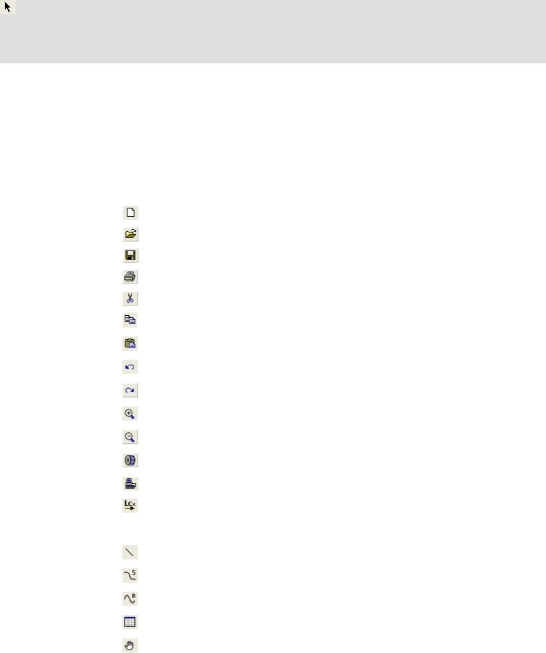
5.5Toolbar
The display is optional.
Via the icons of the toolbar you can easily execute some of the most frequently used menu commands without making a detour via the Menu bar. The selection of the available functions depends on the active mode/window.
Simply click an icon to activate the corresponding command.
|
Icon |
Menu command |
Function |
|
|
|
|
File New |
Creates a new Cam Designer Basic project. |
|
|
|
|
|
|
|
|
File Open |
Opens a Cam Designer Basic project. |
|
|
|
|
|
|
|
|
File Save |
Saves the project under the current name. |
|
|
|
|
|
|
|
|
File Print |
Prints the project. |
|
|
|
|
|
|
|
|
Edit Cut |
Deletes a selected object and moves it to the clipboard. |
|
|
|
|
|
|
|
|
Edit Copy |
Copies a selected object and moves it to the clipboard. |
|
|
|
|
|
|
|
|
Edit Paste |
Pastes a copied or cut object into the current position. |
|
|
|
|
|
|
|
|
Edit Undo |
Undoes the last action. |
|
|
|
|
|
|
|
|
Edit Redo |
Redoes the last undone action. |
|
|
|
|
|
|
|
|
View Zoom In |
Enlarges the worksheet view. |
|
|
|
|
|
|
|
|
View Complete View |
Resets the worksheet view to standard size. |
|
|
|
|
|
|
|
|
Edit |
Opens the acceleration dimensioning dialog. |
|
|
|
Acceleration Dimensioning |
|
|
|
|
|
|
|
|
|
File |
Establishes a connection to the OPC server. |
|
|
|
Connect to OPC Server |
|
|
|
|
|
|
|
|
|
File |
Opens a dialog for selecting a drive. |
|
|
|
Create LCx-file and Download |
|
|
|
|
|
|
|
|
|
Draw Select |
Selects the drawing objects. |
|
|
|
||
|
|
|
|
|
|
|
|
|
|
|
|
|
Draw Line |
Draws a line. |
|
|
|
|
|
|
|
|
Draw Polynomial (5.) |
Draws a 5th grade polynomial. |
|
|
|
|
|
|
|
|
Draw Sloped Sine |
Draws a sloped sine function (Bestehorn). |
|
|
|
|
|
|
|
|
Draw Table |
Draws a table. |
|
|
|
|
|
|
|
|
View Object Input Mode |
Input of motion objects. |
|
|
|
|
|
16 |
2.1 EN - 09/2005 |
L
Loading...