


 Loading...
Automation Systems
Controller
Parameter setting and programming _ _ _ _ _ _ _ _ _ |
Reference Manual |
EN |
Ä.O+Kä 13461042
L
Contents
_ _ _ _ _ _ _ _ _ _ _ _ _ _ _ _ _ _ _ _ _ _ _ _ _ _ _ _ _ _ _ _ _ _ _ _ _ _ _ _ _ _ _ _ _ _ _ _ _ _ _ _ _ _ _ _ _ _ _ _ _ _ _ _
1 |
About this documentation _ _ _ _ _ _ _ _ _ _ _ _ _ _ _ _ _ _ _ _ _ _ _ _ _ _ _ _ _ _ _ _ _ _ _ _ _ _ _ |
6 |
||||||
1.1 |
Document history |
_ _ _ _ _ _ _ _ _ _ _ _ _ _ _ _ _ _ _ _ _ _ _ _ _ _ _ _ _ _ _ _ _ _ _ _ _ _ _ _ _ _ _ _ |
9 |
|||||
1.2 |
Conventions used |
_ _ _ _ _ _ _ _ _ _ _ _ _ _ _ _ _ _ _ _ _ _ _ _ _ _ _ _ _ _ _ _ _ _ _ _ _ _ _ _ _ _ _ _ |
10 |
|||||
1.3 |
Terminology used |
_ _ _ _ _ _ _ _ _ _ _ _ _ _ _ _ _ _ _ _ _ _ _ _ _ _ _ _ _ _ _ _ _ _ _ _ _ _ _ _ _ _ _ _ |
11 |
|||||
1.4 |
Definition of the notes used |
_ _ _ _ _ _ _ _ _ _ _ _ _ _ _ _ _ _ _ _ _ _ _ _ _ _ _ _ _ _ _ _ _ _ _ _ _ _ |
13 |
|||||
2 |
Safety instructions _ _ _ _ _ _ _ _ _ _ _ _ _ _ _ _ _ _ _ _ _ _ _ _ _ _ _ _ _ _ _ _ _ _ _ _ _ _ _ _ _ _ _ _ |
14 |
||||||
3 |
Controller-based Automation: Central motion control |
_ _ _ _ _ _ _ _ _ _ _ _ _ _ _ _ _ _ _ _ _ _ _ _ |
15 |
|||||
4 |
System structure _ _ _ _ _ _ _ _ _ _ _ _ _ _ _ _ _ _ _ _ _ _ _ _ _ _ _ _ _ _ _ _ _ _ _ _ _ _ _ _ _ _ _ _ _ |
18 |
||||||
4.1 |
Engineering tools |
_ _ _ _ _ _ _ _ _ _ _ _ _ _ _ _ _ _ _ _ _ _ _ _ _ _ _ _ _ _ _ _ _ _ _ _ _ _ _ _ _ _ _ _ |
20 |
|||||
4.2 |
Controller: The control centre of the Controller-based Automation _ _ _ _ _ _ _ _ _ _ _ _ _ _ _ _ _ |
22 |
||||||
4.3 |
Runtime software of the Lenze Controllers _ _ _ _ _ _ _ _ _ _ _ _ _ _ _ _ _ _ _ _ _ _ _ _ _ _ _ _ _ _ |
24 |
||||||
|
4.3.1 |
"Logic" runtime software |
_ _ _ _ _ _ _ _ _ _ _ _ _ _ _ _ _ _ _ _ _ _ _ _ _ _ _ _ _ _ _ _ _ _ _ |
25 |
||||
|
4.3.2 |
"Motion" runtime software _ _ _ _ _ _ _ _ _ _ _ _ _ _ _ _ _ _ _ _ _ _ _ _ _ _ _ _ _ _ _ _ _ _ |
25 |
|||||
|
4.3.3 |
"Visu" runtime software _ _ _ _ _ _ _ _ _ _ _ _ _ _ _ _ _ _ _ _ _ _ _ _ _ _ _ _ _ _ _ _ _ _ _ _ |
26 |
|||||
|
|
4.3.3.1 |
Sample topology 1: External monitor panel/display for |
|
|
|||
|
|
|
cabinet controllers _ _ _ _ _ _ _ _ _ _ _ _ _ _ _ _ _ _ _ _ _ _ _ _ _ _ _ _ _ _ _ _ _ |
27 |
||||
|
|
4.3.3.2 |
Sample topology 2: Separate control and visualisation _ _ _ _ _ _ _ _ _ _ _ _ _ |
28 |
||||
|
|
4.3.3.3 |
Sample topology 3: Independent control and visualisation |
|
|
|||
|
|
|
(CANopen) _ _ _ _ _ _ _ _ _ _ _ _ _ _ _ _ _ _ _ _ _ _ _ _ _ _ _ _ _ _ _ _ _ _ _ _ _ |
29 |
||||
5 |
Commissioning the controller _ _ _ _ _ _ _ _ _ _ _ _ _ _ _ _ _ _ _ _ _ _ _ _ _ _ _ _ _ _ _ _ _ _ _ _ _ |
30 |
||||||
5.1 |
Identification _ _ _ _ _ _ _ _ _ _ _ _ _ _ _ _ _ _ _ _ _ _ _ _ _ _ _ _ _ _ _ _ _ _ _ _ _ _ _ _ _ _ _ _ _ _ _ |
31 |
||||||
5.2 |
Control elements of the controllers |
_ _ _ _ _ _ _ _ _ _ _ _ _ _ _ _ _ _ _ _ _ _ _ _ _ _ _ _ _ _ _ _ _ _ |
31 |
|||||
5.3 |
Starting the controller _ _ _ _ _ _ _ _ _ _ _ _ _ _ _ _ _ _ _ _ _ _ _ _ _ _ _ _ _ _ _ _ _ _ _ _ _ _ _ _ _ _ |
32 |
||||||
5.4 |
Configuring the controller |
_ _ _ _ _ _ _ _ _ _ _ _ _ _ _ _ _ _ _ _ _ _ _ _ _ _ _ _ _ _ _ _ _ _ _ _ _ _ _ |
33 |
|||||
|
5.4.1 |
Establishing an automatic dial-up connection _ _ _ _ _ _ _ _ _ _ _ _ _ _ _ _ _ _ _ _ _ _ _ _ |
33 |
|||||
|
5.4.2 |
Entering the IP address of the controller _ _ _ _ _ _ _ _ _ _ _ _ _ _ _ _ _ _ _ _ _ _ _ _ _ _ _ |
33 |
|||||
|
|
5.4.2.1 |
Cabinet controllers with external monitor panels (3231 C/3241 C) |
_ _ _ _ _ _ |
34 |
|||
|
|
5.4.2.2 |
Cabinet Controller without external monitor panel (c300/3221 C) |
_ _ _ _ _ _ |
35 |
|||
|
5.4.3 |
Specifying the IP address of the controller via file (optional) _ _ _ _ _ _ _ _ _ _ _ _ _ _ _ _ |
36 |
|||||
|
5.4.4 |
Establishing Windows® CE access rights _ _ _ _ _ _ _ _ _ _ _ _ _ _ _ _ _ _ _ _ _ _ _ _ _ _ _ |
37 |
|||||
|
|
5.4.4.1 |
Setting up Windows® CE users in »WebConfig« _ _ _ _ _ _ _ _ _ _ _ _ _ _ _ _ _ |
37 |
||||
|
5.4.5 |
Using your own wallpaper on the controller (Windows® CE) _ _ _ _ _ _ _ _ _ _ _ _ _ _ _ _ |
38 |
|||||
5.5 |
I/O system 1000 at the backplane bus of a cabinet controller _ _ _ _ _ _ _ _ _ _ _ _ _ _ _ _ _ _ _ _ |
39 |
||||||
|
5.5.1 |
Configuring I/O modules at the backplane bus |
_ _ _ _ _ _ _ _ _ _ _ _ _ _ _ _ _ _ _ _ _ _ _ |
39 |
||||
|
5.5.2 |
Determining the topology of the I/O modules automatically _ _ _ _ _ _ _ _ _ _ _ _ _ _ _ _ |
41 |
|||||
5.6 |
Tabs of the I/O modules at the backplane bus _ _ _ _ _ _ _ _ _ _ _ _ _ _ _ _ _ _ _ _ _ _ _ _ _ _ _ _ _ |
42 |
||||||
5.7 |
Error messages (backplane bus) _ _ _ _ _ _ _ _ _ _ _ _ _ _ _ _ _ _ _ _ _ _ _ _ _ _ _ _ _ _ _ _ _ _ _ _ |
43 |
||||||
2 |
Lenze · Controller | Parameter setting & programming · Reference Manual · DMS 1.5 EN · 04/2014 · TD17 |
Contents
_ _ _ _ _ _ _ _ _ _ _ _ _ _ _ _ _ _ _ _ _ _ _ _ _ _ _ _ _ _ _ _ _ _ _ _ _ _ _ _ _ _ _ _ _ _ _ _ _ _ _ _ _ _ _ _ _ _ _ _ _ _ _ _
6 |
Parameter setting using »WebConfig« _ _ _ _ _ _ _ _ _ _ _ _ _ _ _ _ _ _ _ _ _ _ _ _ _ _ _ _ _ _ _ _ _ |
45 |
||||||
6.1 |
System structure _ _ _ _ _ _ _ _ _ _ _ _ _ _ _ _ _ _ _ _ _ _ _ _ _ _ _ _ _ _ _ _ _ _ _ _ _ _ _ _ _ _ _ _ _ |
45 |
||||||
6.2 |
Parameterising the controller _ _ _ _ _ _ _ _ _ _ _ _ _ _ _ _ _ _ _ _ _ _ _ _ _ _ _ _ _ _ _ _ _ _ _ _ _ _ |
45 |
||||||
6.3 |
Online connection from the Engineering PC to the controller _ _ _ _ _ _ _ _ _ _ _ _ _ _ _ _ _ _ _ _ |
46 |
||||||
|
6.3.1 |
Setting IP addresses on the Engineering PC (example: Windows® XP) _ _ _ _ _ _ _ _ _ _ _ |
46 |
|||||
6.4 |
Start »WebConfig« |
_ _ _ _ _ _ _ _ _ _ _ _ _ _ _ _ _ _ _ _ _ _ _ _ _ _ _ _ _ _ _ _ _ _ _ _ _ _ _ _ _ _ _ |
47 |
|||||
6.5 |
User interface of »WebConfig« _ _ _ _ _ _ _ _ _ _ _ _ _ _ _ _ _ _ _ _ _ _ _ _ _ _ _ _ _ _ _ _ _ _ _ _ _ |
48 |
||||||
|
6.5.1 |
Device parameters of the controller |
_ _ _ _ _ _ _ _ _ _ _ _ _ _ _ _ _ _ _ _ _ _ _ _ _ _ _ _ _ |
50 |
||||
|
6.5.2 |
Diagnostic/device commands _ _ _ _ _ _ _ _ _ _ _ _ _ _ _ _ _ _ _ _ _ _ _ _ _ _ _ _ _ _ _ _ _ |
51 |
|||||
|
6.5.3 |
Logbook _ _ _ _ _ _ _ _ _ _ _ _ _ _ _ _ _ _ _ _ _ _ _ _ _ _ _ _ _ _ _ _ _ _ _ _ _ _ _ _ _ _ _ _ _ |
52 |
|||||
|
|
6.5.3.1 |
Structure of a logbook entry: example _ _ _ _ _ _ _ _ _ _ _ _ _ _ _ _ _ _ _ _ _ _ |
52 |
||||
|
|
6.5.3.2 |
Filter options _ _ _ _ _ _ _ _ _ _ _ _ _ _ _ _ _ _ _ _ _ _ _ _ _ _ _ _ _ _ _ _ _ _ _ _ |
53 |
||||
|
|
6.5.3.3 |
Time filter for the display of logbook entries |
_ _ _ _ _ _ _ _ _ _ _ _ _ _ _ _ _ _ |
53 |
|||
|
|
6.5.3.4 |
Saving log files with mains failure protection _ _ _ _ _ _ _ _ _ _ _ _ _ _ _ _ _ _ |
54 |
||||
|
|
6.5.3.5 |
Export logbook entries |
_ _ _ _ _ _ _ _ _ _ _ _ _ _ _ _ _ _ _ _ _ _ _ _ _ _ _ _ _ _ |
54 |
|||
|
6.5.4 |
Device commands _ _ _ _ _ _ _ _ _ _ _ _ _ _ _ _ _ _ _ _ _ _ _ _ _ _ _ _ _ _ _ _ _ _ _ _ _ _ _ |
55 |
|||||
|
6.5.5 |
User management _ _ _ _ _ _ _ _ _ _ _ _ _ _ _ _ _ _ _ _ _ _ _ _ _ _ _ _ _ _ _ _ _ _ _ _ _ _ _ |
55 |
|||||
|
6.5.6 |
General parameters _ _ _ _ _ _ _ _ _ _ _ _ _ _ _ _ _ _ _ _ _ _ _ _ _ _ _ _ _ _ _ _ _ _ _ _ _ _ |
55 |
|||||
|
6.5.7 |
Parameters of the communication cards _ _ _ _ _ _ _ _ _ _ _ _ _ _ _ _ _ _ _ _ _ _ _ _ _ _ _ |
56 |
|||||
|
|
6.5.7.1 |
CAN communication card (MC-CAN2) _ _ _ _ _ _ _ _ _ _ _ _ _ _ _ _ _ _ _ _ _ _ |
56 |
||||
|
|
6.5.7.2 |
Optional PROFIBUS/PROFINET communication cards _ _ _ _ _ _ _ _ _ _ _ _ _ _ |
57 |
||||
|
6.5.8 |
Automatic update _ _ _ _ _ _ _ _ _ _ _ _ _ _ _ _ _ _ _ _ _ _ _ _ _ _ _ _ _ _ _ _ _ _ _ _ _ _ _ |
57 |
|||||
|
6.5.9 |
Language selection _ _ _ _ _ _ _ _ _ _ _ _ _ _ _ _ _ _ _ _ _ _ _ _ _ _ _ _ _ _ _ _ _ _ _ _ _ _ _ |
57 |
|||||
|
6.5.10 |
Parameter list buttons _ _ _ _ _ _ _ _ _ _ _ _ _ _ _ _ _ _ _ _ _ _ _ _ _ _ _ _ _ _ _ _ _ _ _ _ _ |
57 |
|||||
7 |
Programming with the »PLC Designer« _ _ _ _ _ _ _ _ _ _ _ _ _ _ _ _ _ _ _ _ _ _ _ _ _ _ _ _ _ _ _ _ |
58 |
||||||
7.1 |
System structure _ _ _ _ _ _ _ _ _ _ _ _ _ _ _ _ _ _ _ _ _ _ _ _ _ _ _ _ _ _ _ _ _ _ _ _ _ _ _ _ _ _ _ _ _ |
59 |
||||||
7.2 |
Function blocks _ _ _ _ _ _ _ _ _ _ _ _ _ _ _ _ _ _ _ _ _ _ _ _ _ _ _ _ _ _ _ _ _ _ _ _ _ _ _ _ _ _ _ _ _ |
60 |
||||||
7.3 |
Configuring and parameterising the controller using the control application _ _ _ _ _ _ _ _ _ _ _ _ |
61 |
||||||
7.4 |
Controller c300/p300: Access to odd Controller addresses _ _ _ _ _ _ _ _ _ _ _ _ _ _ _ _ _ _ _ _ _ _ |
62 |
||||||
7.5 |
Creating remanent variables (retain/persistent) |
_ _ _ _ _ _ _ _ _ _ _ _ _ _ _ _ _ _ _ _ _ _ _ _ _ _ _ |
64 |
|||||
|
7.5.1 |
Storage of retain data on the SD card (only Controllers 3221 C/3231 C) _ _ _ _ _ _ _ _ _ _ |
65 |
|||||
8 |
»Backup & Restore« (data backup/restore) _ _ _ _ _ _ _ _ _ _ _ _ _ _ _ _ _ _ _ _ _ _ _ _ _ _ _ _ _ _ |
67 |
||||||
9 |
Data integrity in the event of a voltage failure _ _ _ _ _ _ _ _ _ _ _ _ _ _ _ _ _ _ _ _ _ _ _ _ _ _ _ _ |
68 |
||||||
9.1 |
UPS functionality of the controllers _ _ _ _ _ _ _ _ _ _ _ _ _ _ _ _ _ _ _ _ _ _ _ _ _ _ _ _ _ _ _ _ _ _ |
68 |
||||||
|
9.1.1 |
Internal UPS (for Controllers without UPS connection) |
_ _ _ _ _ _ _ _ _ _ _ _ _ _ _ _ _ _ _ |
68 |
||||
|
9.1.2 |
External UPS (for Controllers 3241 C with UPS connection) _ _ _ _ _ _ _ _ _ _ _ _ _ _ _ _ _ |
69 |
|||||
9.2 |
Storage of »VisiWinNET® Smart« visualisation data |
_ _ _ _ _ _ _ _ _ _ _ _ _ _ _ _ _ _ _ _ _ _ _ _ _ |
70 |
|||||
9.3 |
Storage of retain/persistent variables of the PLC _ _ _ _ _ _ _ _ _ _ _ _ _ _ _ _ _ _ _ _ _ _ _ _ _ _ _ |
71 |
||||||
10 |
Device replacement - replacing the controller (in the event of service) _ _ _ _ _ _ _ _ _ _ _ _ _ _ _ |
72 |
||||||
10.1 |
Removing the connected (defective) controller |
_ _ _ _ _ _ _ _ _ _ _ _ _ _ _ _ _ _ _ _ _ _ _ _ _ _ _ _ |
72 |
|||||
10.2 |
Connecting the new controller/replacement device |
_ _ _ _ _ _ _ _ _ _ _ _ _ _ _ _ _ _ _ _ _ _ _ _ _ |
73 |
|||||
10.3 |
After the device replacement: Automatic data update _ _ _ _ _ _ _ _ _ _ _ _ _ _ _ _ _ _ _ _ _ _ _ _ |
75 |
||||||
10.4 |
Subsequent use of retain data on the new controller _ _ _ _ _ _ _ _ _ _ _ _ _ _ _ _ _ _ _ _ _ _ _ _ _ |
77 |
||||||
10.5 |
Error messages after a device replacement |
_ _ _ _ _ _ _ _ _ _ _ _ _ _ _ _ _ _ _ _ _ _ _ _ _ _ _ _ _ _ |
78 |
|||||
Lenze · Controller | Parameter setting & programming · Reference Manual · DMS 1.5 EN · 04/2014 · TD17 |
3 |
Contents
_ _ _ _ _ _ _ _ _ _ _ _ _ _ _ _ _ _ _ _ _ _ _ _ _ _ _ _ _ _ _ _ _ _ _ _ _ _ _ _ _ _ _ _ _ _ _ _ _ _ _ _ _ _ _ _ _ _ _ _ _ _ _ _
11 |
Remote maintenance and diagnostics _ _ _ _ _ _ _ _ _ _ _ _ _ _ _ _ _ _ _ _ _ _ _ _ _ _ _ _ _ _ _ _ _ |
79 |
|
11.1 |
Status LEDs of the Controllers _ _ _ _ _ _ _ _ _ _ _ _ _ _ _ _ _ _ _ _ _ _ _ _ _ _ _ _ _ _ _ _ _ _ _ _ _ |
80 |
|
11.2 |
Diagnostics via Telnet _ _ _ _ _ _ _ _ _ _ _ _ _ _ _ _ _ _ _ _ _ _ _ _ _ _ _ _ _ _ _ _ _ _ _ _ _ _ _ _ _ _ |
82 |
|
|
11.2.1 |
»WebConfig« settings _ _ _ _ _ _ _ _ _ _ _ _ _ _ _ _ _ _ _ _ _ _ _ _ _ _ _ _ _ _ _ _ _ _ _ _ _ |
83 |
11.3 |
Data transfer via FTP _ _ _ _ _ _ _ _ _ _ _ _ _ _ _ _ _ _ _ _ _ _ _ _ _ _ _ _ _ _ _ _ _ _ _ _ _ _ _ _ _ _ |
85 |
|
|
11.3.1 FTP settings with the »WebConfig« _ _ _ _ _ _ _ _ _ _ _ _ _ _ _ _ _ _ _ _ _ _ _ _ _ _ _ _ _ _ |
86 |
|
|
11.3.2 |
FTP and web settings in the Internet Explorer _ _ _ _ _ _ _ _ _ _ _ _ _ _ _ _ _ _ _ _ _ _ _ _ |
87 |
11.4 |
Diagnostics with the logbook _ _ _ _ _ _ _ _ _ _ _ _ _ _ _ _ _ _ _ _ _ _ _ _ _ _ _ _ _ _ _ _ _ _ _ _ _ _ |
89 |
|
|
11.4.1 |
Logbook query via »WebConfig« _ _ _ _ _ _ _ _ _ _ _ _ _ _ _ _ _ _ _ _ _ _ _ _ _ _ _ _ _ _ _ |
90 |
|
11.4.2 |
Logbook parameters _ _ _ _ _ _ _ _ _ _ _ _ _ _ _ _ _ _ _ _ _ _ _ _ _ _ _ _ _ _ _ _ _ _ _ _ _ _ |
91 |
11.5 |
Activate Windows® CE interface _ _ _ _ _ _ _ _ _ _ _ _ _ _ _ _ _ _ _ _ _ _ _ _ _ _ _ _ _ _ _ _ _ _ _ _ |
92 |
|
|
11.5.1 |
Remote Display: Remote control of Controller via Internet or LAN _ _ _ _ _ _ _ _ _ _ _ _ _ |
94 |
|
11.5.2 |
Virtual Network Computing (VNC) _ _ _ _ _ _ _ _ _ _ _ _ _ _ _ _ _ _ _ _ _ _ _ _ _ _ _ _ _ _ |
95 |
12 |
Visualisation with »VisiWinNET®« _ _ _ _ _ _ _ _ _ _ _ _ _ _ _ _ _ _ _ _ _ _ _ _ _ _ _ _ _ _ _ _ _ _ _ |
96 |
|
12.1 |
Visualisation on the controller: local and remote _ _ _ _ _ _ _ _ _ _ _ _ _ _ _ _ _ _ _ _ _ _ _ _ _ _ _ |
97 |
|
12.2 |
System structure _ _ _ _ _ _ _ _ _ _ _ _ _ _ _ _ _ _ _ _ _ _ _ _ _ _ _ _ _ _ _ _ _ _ _ _ _ _ _ _ _ _ _ _ _ |
98 |
|
12.3 |
Using the visualisation to access data of the control/parameters _ _ _ _ _ _ _ _ _ _ _ _ _ _ _ _ _ _ |
99 |
|
12.4 |
Use the Direct driver "LogicAndMotionV3" (local visualisation) _ _ _ _ _ _ _ _ _ _ _ _ _ _ _ _ _ _ _ |
101 |
|
12.4.1Selecting the target device using the Windows® CE operating system
|
|
(example 3200 C/p500) _ _ _ _ _ _ _ _ _ _ _ _ _ _ _ _ _ _ _ _ _ _ _ _ _ _ _ _ _ _ _ _ _ _ _ _ |
102 |
|
|
12.4.2 |
Project Explorer _ _ _ _ _ _ _ _ _ _ _ _ _ _ _ _ _ _ _ _ _ _ _ _ _ _ _ _ _ _ _ _ _ _ _ _ _ _ _ _ |
104 |
|
|
12.4.3 |
Using the variables browser to access variables (browse variables) _ _ _ _ _ _ _ _ _ _ _ _ |
105 |
|
|
12.4.4 |
Accept variable definitions to project _ _ _ _ _ _ _ _ _ _ _ _ _ _ _ _ _ _ _ _ _ _ _ _ _ _ _ _ _ |
107 |
|
|
12.4.5 |
Creating control elements/linking them to variables _ _ _ _ _ _ _ _ _ _ _ _ _ _ _ _ _ _ _ _ |
108 |
|
|
12.4.6 |
Transferring an application to the target device _ _ _ _ _ _ _ _ _ _ _ _ _ _ _ _ _ _ _ _ _ _ _ |
109 |
|
|
12.4.7 |
Start the »VisiWinNET®« _ _ _ _ _ _ _ _ _ _ _ _ _ _ _ _ _ _ _ _ _ _ _ _ _ _ _ _ _ _ _ _ _ _ _ |
110 |
|
12.5 |
Using the LogicAndMotionV3 direct driver (remote access) _ _ _ _ _ _ _ _ _ _ _ _ _ _ _ _ _ _ _ _ _ |
111 |
||
12.6 |
OPC tunnel for local visualisation (integrated control system) _ _ _ _ _ _ _ _ _ _ _ _ _ _ _ _ _ _ _ _ |
112 |
||
|
12.6.1 |
Integrating the OPC tunnel in »VisiWinNET®« _ _ _ _ _ _ _ _ _ _ _ _ _ _ _ _ _ _ _ _ _ _ _ _ |
113 |
|
|
12.6.2 |
Browsing variable definitions / configuring the device _ _ _ _ _ _ _ _ _ _ _ _ _ _ _ _ _ _ _ |
114 |
|
|
12.6.3 |
Manual integration of variables (experts only - background knowledge required!) _ _ _ _ |
116 |
|
|
12.6.4 |
Configure OPC tunnel _ _ _ _ _ _ _ _ _ _ _ _ _ _ _ _ _ _ _ _ _ _ _ _ _ _ _ _ _ _ _ _ _ _ _ _ _ |
119 |
|
12.7 |
OPC tunnel for external visualisation (remote access) _ _ _ _ _ _ _ _ _ _ _ _ _ _ _ _ _ _ _ _ _ _ _ _ |
120 |
||
|
12.7.1 |
Windows® CE operating system _ _ _ _ _ _ _ _ _ _ _ _ _ _ _ _ _ _ _ _ _ _ _ _ _ _ _ _ _ _ _ |
120 |
|
|
|
12.7.1.1 |
Configure OPC tunnel for remote access (Windows® CE) _ _ _ _ _ _ _ _ _ _ _ _ |
121 |
|
12.7.2 |
Windows® XP/XP Embedded operating system _ _ _ _ _ _ _ _ _ _ _ _ _ _ _ _ _ _ _ _ _ _ _ |
122 |
|
|
|
12.7.2.1 |
Configure OPC tunnel for remote access (Windows® XP/XP Embedded) _ _ _ |
123 |
|
12.7.3 |
Browsing variables _ _ _ _ _ _ _ _ _ _ _ _ _ _ _ _ _ _ _ _ _ _ _ _ _ _ _ _ _ _ _ _ _ _ _ _ _ _ _ |
124 |
|
12.8 |
Lenze specifications _ _ _ _ _ _ _ _ _ _ _ _ _ _ _ _ _ _ _ _ _ _ _ _ _ _ _ _ _ _ _ _ _ _ _ _ _ _ _ _ _ _ _ |
126 |
||
|
12.8.1 Install additional fonts _ _ _ _ _ _ _ _ _ _ _ _ _ _ _ _ _ _ _ _ _ _ _ _ _ _ _ _ _ _ _ _ _ _ _ _ _ |
126 |
||
12.8.2Timeout (waiting position) of the CAN OPC server influences the time response of the
visualisation _ _ _ _ _ _ _ _ _ _ _ _ _ _ _ _ _ _ _ _ _ _ _ _ _ _ _ _ _ _ _ _ _ _ _ _ _ _ _ _ _ _ |
126 |
4 |
Lenze · Controller | Parameter setting & programming · Reference Manual · DMS 1.5 EN · 04/2014 · TD17 |
Contents
_ _ _ _ _ _ _ _ _ _ _ _ _ _ _ _ _ _ _ _ _ _ _ _ _ _ _ _ _ _ _ _ _ _ _ _ _ _ _ _ _ _ _ _ _ _ _ _ _ _ _ _ _ _ _ _ _ _ _ _ _ _ _ _
13 |
Parameter reference _ _ _ _ _ _ _ _ _ _ _ _ _ _ _ _ _ _ _ _ _ _ _ _ _ _ _ _ _ _ _ _ _ _ _ _ _ _ _ _ _ _ _ |
127 |
||||
13.1 |
Structure of the parameter description |
_ _ _ _ _ _ _ _ _ _ _ _ _ _ _ _ _ _ _ _ _ _ _ _ _ _ _ _ _ _ _ _ |
128 |
|||
|
13.1.1 |
Data types |
_ _ _ _ _ _ _ _ _ _ _ _ _ _ _ _ _ _ _ _ _ _ _ _ _ _ _ _ _ _ _ _ _ _ _ _ _ _ _ _ _ _ _ |
128 |
||
|
13.1.2 Parameters with read access |
_ _ _ _ _ _ _ _ _ _ _ _ _ _ _ _ _ _ _ _ _ _ _ _ _ _ _ _ _ _ _ _ _ |
129 |
|||
|
13.1.3 |
Parameters with write access _ _ _ _ _ _ _ _ _ _ _ _ _ _ _ _ _ _ _ _ _ _ _ _ _ _ _ _ _ _ _ _ _ |
129 |
|||
|
|
13.1.3.1 |
Parameters with a setting range |
_ _ _ _ _ _ _ _ _ _ _ _ _ _ _ _ _ _ _ _ _ _ _ _ _ |
129 |
|
|
|
13.1.3.2 |
Parameters with a selection list |
_ _ _ _ _ _ _ _ _ _ _ _ _ _ _ _ _ _ _ _ _ _ _ _ _ |
129 |
|
|
|
13.1.3.3 |
Parameters with a bit-coded setting _ _ _ _ _ _ _ _ _ _ _ _ _ _ _ _ _ _ _ _ _ _ _ |
130 |
||
|
13.1.4 Parameter attributes _ _ _ _ _ _ _ _ _ _ _ _ _ _ _ _ _ _ _ _ _ _ _ _ _ _ _ _ _ _ _ _ _ _ _ _ _ _ |
130 |
||||
13.2 |
Basic parameters of the Controllers 3200 C/c300 and p300/p500 _ _ _ _ _ _ _ _ _ _ _ _ _ _ _ _ _ _ |
131 |
||||
13.3 |
Voltage buffering by external UPS (optional, for Controller 3241 C) _ _ _ _ _ _ _ _ _ _ _ _ _ _ _ _ _ |
158 |
||||
13.4 |
Ethernet (on board) |
_ _ _ _ _ _ _ _ _ _ _ _ _ _ _ _ _ _ _ _ _ _ _ _ _ _ _ _ _ _ _ _ _ _ _ _ _ _ _ _ _ _ _ |
161 |
|||
13.5 |
EtherCAT _ _ _ _ _ _ _ _ _ _ _ _ _ _ _ _ _ _ _ _ _ _ _ _ _ _ _ _ _ _ _ _ _ _ _ _ _ _ _ _ _ _ _ _ _ _ _ _ _ |
163 |
||||
13.6 |
Monitor panel (integrated/external) _ _ _ _ _ _ _ _ _ _ _ _ _ _ _ _ _ _ _ _ _ _ _ _ _ _ _ _ _ _ _ _ _ _ |
168 |
||||
13.7 |
PLC (Logic/Motion) |
_ _ _ _ _ _ _ _ _ _ _ _ _ _ _ _ _ _ _ _ _ _ _ _ _ _ _ _ _ _ _ _ _ _ _ _ _ _ _ _ _ _ _ |
172 |
|||
13.8 |
Backup&Restore _ _ _ _ _ _ _ _ _ _ _ _ _ _ _ _ _ _ _ _ _ _ _ _ _ _ _ _ _ _ _ _ _ _ _ _ _ _ _ _ _ _ _ _ _ |
174 |
||||
13.9 |
Communication cards: optional interface _ _ _ _ _ _ _ _ _ _ _ _ _ _ _ _ _ _ _ _ _ _ _ _ _ _ _ _ _ _ _ |
178 |
||||
|
13.9.1 |
CAN (MC-CAN2) communication card / CAN interface for Controller c300/p300 _ _ _ _ _ |
179 |
|||
|
13.9.2 |
PROFIBUS and PROFINET communication cards _ _ _ _ _ _ _ _ _ _ _ _ _ _ _ _ _ _ _ _ _ _ _ |
185 |
|||
|
Index _ _ _ _ _ _ _ _ _ _ _ _ _ _ _ _ _ _ _ _ _ _ _ _ _ _ _ _ _ _ _ _ _ _ _ _ _ _ _ _ _ _ _ _ _ _ _ _ _ _ _ |
187 |
||||
|
Your opinion is important to us _ _ _ _ _ _ _ _ _ _ _ _ _ _ _ _ _ _ _ _ _ _ _ _ _ _ _ _ _ _ _ _ _ _ _ _ _ |
194 |
||||
Lenze · Controller | Parameter setting & programming · Reference Manual · DMS 1.5 EN · 04/2014 · TD17 |
5 |

1 About this documentation
_ _ _ _ _ _ _ _ _ _ _ _ _ _ _ _ _ _ _ _ _ _ _ _ _ _ _ _ _ _ _ _ _ _ _ _ _ _ _ _ _ _ _ _ _ _ _ _ _ _ _ _ _ _ _ _ _ _ _ _ _ _ _ _
1 |
About this documentation |
This documentation contains general information on how to parameterise, configure and diagnose the Lenze Controllers.
This manual is part of the "Controller-based Automation" manual collection. It consists of the following sets of documentation:
Documentation type |
Subject |
System manuals |
System overview/sample topologies |
|
• Controller-based Automation |
|
• Visualization |
Communication manuals |
Bus systems |
Online helps |
• Controller-based Automation EtherCAT® |
|
• Controller-based Automation CANopen® |
|
• Controller-based Automation PROFIBUS® |
|
• Controller-based Automation PROFINET® |
Reference manuals |
Lenze Controller: |
Online helps |
• Controller 3200 C |
|
• Controller c300 |
|
• Controller p300 |
|
• Controller p500 |
Software manuals |
Lenze Engineering Tools: |
Online helps |
• »PLC Designer«: Programming |
|
• »Engineer«: Inverter configuration |
|
• »VisiWinNET® Smart«: Visualisation |
|
• »Backup & Restore«: Back up/restore data |
|
|
Information on how to use the controllers outside the control technology can be found in the system manuals created for the prevailing application case.
Lenze · Controller | Parameter setting & programming · Reference Manual · DMS 1.5 EN · 04/2014 · TD17 |
6 |

1 About this documentation
_ _ _ _ _ _ _ _ _ _ _ _ _ _ _ _ _ _ _ _ _ _ _ _ _ _ _ _ _ _ _ _ _ _ _ _ _ _ _ _ _ _ _ _ _ _ _ _ _ _ _ _ _ _ _ _ _ _ _ _ _ _ _ _
More technical documentation for Lenze components
Further information on Lenze products which can be used in conjunction with Controller-based Automation can be found in the following sets of documentation:
Mounting & wiring
Mounting instructions
•Controller
•Communication cards (MC-xxx)
•I/O system 1000 (EPM-Sxxx)
•Inverter, Servo Drives
•Communication modules
Operating instructions
•Controller
•Servo system ECS (ECSxE, ECSxM)
Sample applications/Using application templates
Online help/software manuals
•Application Sample i700
•Application Samples
•ApplicationTemplate
Parameterisation, configuration, commissioning
Online help/reference manuals
•Controller
•Inverter, Servo Drives
•I/O system 1000 (EPM-Sxxx)
Online help/communication manuals
•Bus systems
•Communication modules
Operating instructions
•Servo system ECS (ECSxE, ECSxM)
Symbols:
Printed documentation
Online help in the Lenze Engineering Tool (also available as PDF file at www.lenze.com.)
Tip!
Current documentation and software updates with regard to Lenze products can be found in the download area at:
www.lenze.com
Target group
This documentation is intended for persons who commission and maintain a Controller-based automation system by means of a Lenze Controller and the »PLC Designer« engineering tool.
Screenshots/application examples
All screenshots in this documentation are application examples. Depending on the firmware version of the field devices and the software version of the Engineering tools installed (e.g. »PLC Designer« ), screenshots in this documentation may differ from the representation on the screen.
7 |
Lenze · Controller | Parameter setting & programming · Reference Manual · DMS 1.5 EN · 04/2014 · TD17 |
1 About this documentation
_ _ _ _ _ _ _ _ _ _ _ _ _ _ _ _ _ _ _ _ _ _ _ _ _ _ _ _ _ _ _ _ _ _ _ _ _ _ _ _ _ _ _ _ _ _ _ _ _ _ _ _ _ _ _ _ _ _ _ _ _ _ _ _
Information regarding the validity
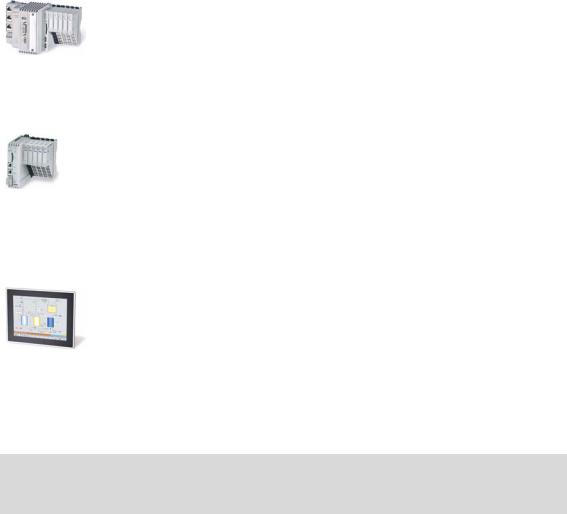
The information provided in this documentation is valid for the following Lenze Controllers:
Controller |
Versions |
Cabinet Controller |
|
|
• Controller 3221 C |
|
• Controller 3231 C |
|
• Controller 3241 C |
Example: Controller 3241 C with connected I/O system 1000 |
|
|
• Controller c300 |
Example: Controller c300 with connected I/O system 1000 |
|
Panel Controller |
|
|
• Controller p300 |
|
• Controller p500 |
Example: Controller p500 |
|
|
|
Operating instructions/mounting instructions of the Controllers
Here you will find technical data and information on how to install the devices.
Lenze · Controller | Parameter setting & programming · Reference Manual · DMS 1.5 EN · 04/2014 · TD17 |
8 |
1 About this documentation
1.1Document history
_ _ _ _ _ _ _ _ _ _ _ _ _ _ _ _ _ _ _ _ _ _ _ _ _ _ _ _ _ _ _ _ _ _ _ _ _ _ _ _ _ _ _ _ _ _ _ _ _ _ _ _ _ _ _ _ _ _ _ _ _ _ _ _
1.1Document history
Version |
|
|
Description |
|
1.0 |
|
10/2010 |
TD11 |
First edition for the Lenze automation system "Controller-based Automation" 3.x |
1.1 |
|
04/2011 |
TD11 |
Update for the Lenze automation system "Controller-based Automation" 3.1 |
1.2 |
|
12/2011 |
TD11 |
Update for the Lenze automation system "Controller-based Automation" 3.2 |
1.3 |
|
05/2012 |
TD11 |
Update for the Lenze automation system "Controller-based Automation" 3.3 |
|
|
|
|
• Amended by Controllers p500 (panel controllers) |
1.4 |
|
11/2012 |
TD11 |
Update for the Lenze automation system "Controller-based Automation" 3.6 |
|
|
|
|
• Controller c300/p300 added (in preparation) |
1.5 |
|
04/2014 |
TD17 |
Update for the Lenze automation system "Controller-based Automation" 3.8 |
|
|
|
|
• Controller c300/p300 |
|
|
|
|
|
9 |
Lenze · Controller | Parameter setting & programming · Reference Manual · DMS 1.5 EN · 04/2014 · TD17 |
1 About this documentation
1.2Conventions used
_ _ _ _ _ _ _ _ _ _ _ _ _ _ _ _ _ _ _ _ _ _ _ _ _ _ _ _ _ _ _ _ _ _ _ _ _ _ _ _ _ _ _ _ _ _ _ _ _ _ _ _ _ _ _ _ _ _ _ _ _ _ _ _
1.2Conventions used
This documentation uses the following conventions to distinguish between different types of information:
Type of information |
Highlighting |
Examples/notes |
Spelling of numbers |
|
|
Decimal separators |
Point |
The decimal point is generally used. |
|
|
For example: 1234.56 |
Text |
|
|
Version information |
Text colour blue |
All pieces of information that only apply to or from a specific |
|
|
software version of the inverter are highlighted |
|
|
correspondingly in this documentation. |
|
|
Example: This function extension is available from software |
|
|
version V3.0! |
Program name |
» « |
»PLC Designer«... |
Window |
italics |
The message window... / The Options dialog box ... |
Variable names |
|
Setting bEnable to TRUE... |
Control element |
bold |
The OK button ... / The Copy command ... / The Properties tab |
|
|
... / The Name input field ... |
Sequence of menu |
|
If several commands must be used in sequence to carry out a |
commands |
|
function, the individual commands are separated by an |
|
|
arrow: Select File Open to... |
Shortcut |
<bold> |
Use <F1> to open the online help. |
|
|
|
|
|
If a key combination is required for a command, a "+" is |
|
|
placed between the key identifiers: With <Shift>+<ESC>... |
Hyperlink |
underlined |
Reference to further information: Hyperlink to further |
|
|
information. |
Symbols |
|
|
Page reference |
( 10) |
Reference to further information: Page number in PDF file. |
Step-by-step instructions |
|
Step-by-step instructions are marked by a pictograph. |
Lenze · Controller | Parameter setting & programming · Reference Manual · DMS 1.5 EN · 04/2014 · TD17 |
10 |
1 About this documentation
1.3Terminology used
_ _ _ _ _ _ _ _ _ _ _ _ _ _ _ _ _ _ _ _ _ _ _ _ _ _ _ _ _ _ _ _ _ _ _ _ _ _ _ _ _ _ _ _ _ _ _ _ _ _ _ _ _ _ _ _ _ _ _ _ _ _ _ _
1.3Terminology used
Term |
Meaning |
Controller |
The controller is the central component of the automation system which controls the |
|
Logic and Motion functionalities by means of the runtime software. |
|
The controller communicates with the field devices via the fieldbus. |
|
|
Engineering PC |
The Engineering PC and the Engineering tools installed serve to configure and |
|
parameterise the system "Controller-based Automation". |
|
The Engineering PC communicates with the controller via Ethernet. |
|
|
Fieldbus stations |
Devices integrated in the bus system as, for instance, Controller and inverter |
|
|
Field device |
|
|
|
Inverter |
Generic term for Lenze frequency inverter, servo inverter |
|
|
PLC |
Programmable Logic Controller |
|
|
PLC |
Programmable Logic Controller (PLC) |
|
|
UPS |
Uninterruptible power system (UPS) |
|
|
Engineering tools
Software solutions for easy engineering in all phases which serve to commission, configure, parameterise and diagnose the Lenze automation system.
Engineering tools ( 20)
»EASY Navigator« – provides for orientation
• All convenient Lenze Engineering tools at a glance
• Tools can be selected quickly
• Simplifies the access to the engineering process by its clarity.
»EASY Starter« – easy-to-use tool for service technicians
• For the maintenance of Lenze devices
• For the commissioning of Lenze devices
• Online diagnostics, parameterisation and commissioning
• Loading of ready-to-use applications to the device
»Engineer« – multi-device engineering
• Suitable for all products of the Lenze portfolio
• Easy handling by means of graphical user interfaces
•
Can be used in all engineering phases (project planning, commissioning, production)
• Parameterisation and configuration of Lenze devices
»PLC Designer« – programming processes
• Creating individual programs
• Programming Logic & Motion according to IEC 61131-3 (AWL, KOP, FUP, ST, AS and CFC-Editor), based on CoDeSys V3
• Certified function blocks according to PLCopen part 1 + 2
• Graphic DIN 66025 Editor (G code) with DXF import
• Integrated visualisation for the simple representation of processes
»VisiWinNET« – visualisation tool
• Visualise the applications of the automation system
• Create the visualisation/user interface
»Backup & Restore« – back up/restore/update data
• Create data backups
• Restore data after device replacement
• Carry out software update of the Controller
Bus systems
CAN |
CAN (Controller Area Network) is an asynchronous, serial fieldbus system. |
|
|
|
CANopen® is a communication protocol based on CAN. The Lenze system bus (CAN on |
|
board) operates with a subset of this communication protocol. |
|
CANopen® is a registered community trademark of the CAN user organisation CiA® (CAN |
|
in Automation e. V.). |
|
|
11 |
Lenze · Controller | Parameter setting & programming · Reference Manual · DMS 1.5 EN · 04/2014 · TD17 |

1 About this documentation
1.3Terminology used
_ _ _ _ _ _ _ _ _ _ _ _ _ _ _ _ _ _ _ _ _ _ _ _ _ _ _ _ _ _ _ _ _ _ _ _ _ _ _ _ _ _ _ _ _ _ _ _ _ _ _ _ _ _ _ _ _ _ _ _ _ _ _ _
Term |
Meaning |
|
EtherCAT® (Ethernet for Controller and Automation Technology) is an Ethernet-based |
|
fieldbus system which fulfils the application profile for industrial real-time systems. |
|
EtherCAT® is a registered trademark and patented technology, licensed by Beckhoff |
|
Automation GmbH, Germany. |
|
PROFIBUS® (Process Field Bus) is a widely used fieldbus system for the automation of |
|
machines and production lines. |
|
PROFIBUS® is a registered trademark and patented technology licensed by the PROFIBUS |
|
& PROFINET International (PI) user organisation. |
|
PROFINET® (Process Field Network) is a real-time capable fieldbus system based on |
|
Ethernet. |
|
PROFINET® is a registered trademark and patented technology licensed by the PROFIBUS |
|
& PROFINET International (PI) user organisation. |
|
|
Lenze · Controller | Parameter setting & programming · Reference Manual · DMS 1.5 EN · 04/2014 · TD17 |
12 |

1 About this documentation
1.4Definition of the notes used
_ _ _ _ _ _ _ _ _ _ _ _ _ _ _ _ _ _ _ _ _ _ _ _ _ _ _ _ _ _ _ _ _ _ _ _ _ _ _ _ _ _ _ _ _ _ _ _ _ _ _ _ _ _ _ _ _ _ _ _ _ _ _ _
1.4Definition of the notes used
This documentation uses the following signal words and symbols to indicate dangers and important information:
Safety instructions
Structure of the safety instructions:
Pictograph and signal word!
(characterises the type and severity of danger)
Note
(describes the danger and informs how to prevent dangerous situations)
Pictograph |
Signal word |
Meaning |
|
Danger! |
Danger of personal injuries through dangerous electrical voltage |
|
Reference to an imminent danger that may result in death or serious personal |
|
|
injury unless the corresponding measures are taken. |
|
|
Danger! |
Danger of personal injury through a general source of danger |
|
Reference to an imminent danger that may result in death or serious personal |
|
|
injury unless the corresponding measures are taken. |
|
|
Stop! |
Danger of material damage |
|
Indicates a potential danger that may lead to material damage unless the |
|
|
corresponding measures are taken. |
|
Application notes |
|
|
|
|
|
Pictograph |
Signal word |
Meaning |
|
|
|
Note! Important note to ensure troublefree operation
Tip! Useful tip for easy handling
|
Reference to another document |
|
13 |
Lenze · Controller | Parameter setting & programming · Reference Manual · DMS 1.5 EN · 04/2014 · TD17 |

2 Safety instructions
_ _ _ _ _ _ _ _ _ _ _ _ _ _ _ _ _ _ _ _ _ _ _ _ _ _ _ _ _ _ _ _ _ _ _ _ _ _ _ _ _ _ _ _ _ _ _ _ _ _ _ _ _ _ _ _ _ _ _ _ _ _ _ _
2 |
Safety instructions |
Please observe the following safety instructions when you want to commission an automation system or a plant using a controller.
Read the documentation supplied with the corresponding field device thoroughly before starting to commission the devices with the controller!
The device documentation contains safety instructions which must be observed!
Danger!
According to today's scientific knowledge it is not possible to ensure absolute freedom from defects of a software.
If necessary, systems with built-in inverters must be provided with additional monitoring and protective equipment complying with the relevant safety regulations (e.g. law on technical equipment, regulations for the prevention of accidents) in each case, so that an impermissible operating status does not endanger persons or facilities.
During commissioning persons must keep a safe distance from the motor or the machine parts driven by the motor. Otherwise there would be a risk of injury by the moving machine parts.
Stop!
If you change parameters in the engineering software while a device is connected online, the changes will be directly accepted by the device.
A wrong parameter setting can cause unpredictable motor movements.
By an unintended direction of rotation, too high speed, or jerky operation, the driven machine parts may be damaged.
Lenze · Controller | Parameter setting & programming · Reference Manual · DMS 1.5 EN · 04/2014 · TD17 |
14 |
3 Controller-based Automation: Central motion control
_ _ _ _ _ _ _ _ _ _ _ _ _ _ _ _ _ _ _ _ _ _ _ _ _ _ _ _ _ _ _ _ _ _ _ _ _ _ _ _ _ _ _ _ _ _ _ _ _ _ _ _ _ _ _ _ _ _ _ _ _ _ _ _
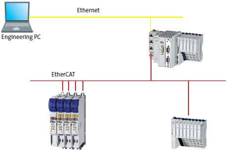
3 Controller-based Automation: Central motion control
The Lenze automation system "Controller-based Automation" serves to create complex automation solutions with central motion control. Here, the Controller is the control centre of the system.
System structure of the Controller-based Automation: "All from one single source"
[3-1] Example configuration (EtherCAT bus system): Controller 3200 C with I/O system 1000 and Servo Inverter i700.
15 |
Lenze · Controller | Parameter setting & programming · Reference Manual · DMS 1.5 EN · 04/2014 · TD17 |
3 Controller-based Automation: Central motion control
_ _ _ _ _ _ _ _ _ _ _ _ _ _ _ _ _ _ _ _ _ _ _ _ _ _ _ _ _ _ _ _ _ _ _ _ _ _ _ _ _ _ _ _ _ _ _ _ _ _ _ _ _ _ _ _ _ _ _ _ _ _ _ _
Lenze supply specially matched system components:
•Engineering software
The Lenze Engineering tools ( 20) on your Engineering PC (Windows® operating system) serve to parameterise, configure and diagnose the system. The Engineering PC communicates with the Controller via Ethernet.
•Controller
The Lenze Controller is available as Panel Controller with integrated touch display and as Cabinet Controller in control cabinet design.
Cabinet Controllers provide a direct coupling of the I/O system 100 via the integrated backplane bus.
The Runtime software of the Lenze Controllers ( 24) provides the control and/or visualisation of motion sequences. These software versions are available:
•"Logic": Sequence control in the Controller, motion control in the inverter
•"Motion": Sequence control and motion control in the Controller, inverter as actuating drive
•"Visu": Optional visualisation of the automation system, can be used separately or in addition to "Logic" or "Motion"
An external monitor panel/display can be connected to the Cabinet Controller 3231 C/ 3241 C.
•Without software: Controller as single component with operating system only
•Bus systems
EtherCAT is a standard "on board" bus system of the Controller-based Automation. EtherCAT enables the control of all nodes (Motion/Logic) on one common fieldbus.
Optionally, CANopen, PROFIBUS and PROFINET can be used as extended topologies.
The Controllers c300/p300 have a CANopen interface "on board" as well (in addition to EtherCAT).
•Inverter (e.g. Servo Inverter i700)
"Logic & Motion" runtime software
The "Controller-based Automation" system allows for the central control of devices for Logic and Motion applications. The runtime software runs on the Controller.
In case of Logic applications, the sequence control is carried out in the Controller and the motion control is carried out in the inverter.
In case of Motion applications , the sequence control and motion control are carried out in the Controller. The inverter is used as actuating drive.
•Motion applications make special demands on the cycle time and real-time capability of the bus system between the Controller and the subordinate fieldbus nodes.
•This is e.g. the case if the nodes must traverse synchronously or if position setpoints must be transmitted.
Lenze · Controller | Parameter setting & programming · Reference Manual · DMS 1.5 EN · 04/2014 · TD17 |
16 |

3 Controller-based Automation: Central motion control
_ _ _ _ _ _ _ _ _ _ _ _ _ _ _ _ _ _ _ _ _ _ _ _ _ _ _ _ _ _ _ _ _ _ _ _ _ _ _ _ _ _ _ _ _ _ _ _ _ _ _ _ _ _ _ _ _ _ _ _ _ _ _ _
Fieldbus communication
The Lenze Controllers have different interfaces for fieldbus communication:
Area |
|
Cabinet Controller |
|
Panel Controller |
||
|
c300 |
3221 C |
3231 C |
3241 C |
p300 |
p500 |
Interfaces (on board) |
|
|
|
|
|
|
Ethernet |
1 |
|
2 |
|
1 |
2 |
EtherCAT |
1 1) |
|
1 |
|
1 1) |
1 |
CANopen |
1 2) |
|
- |
|
1 2) |
- |
Optional interfaces (communication cards) |
|
|
|
|
||
CANopen |
- |
|
|
|
- |
|
MC-CAN2 |
|
|
|
|
|
|
PROFIBUS master |
- |
|
|
|
- |
|
MC-PBM |
|
|
|
|
|
|
PROFIBUS slave |
- |
|
|
|
- |
|
MC-PBS |
|
|
|
|
|
|
PROFINET device |
- |
|
|
|
- |
|
MC-PND |
|
|
|
|
|
|
|
|
|
|
|
|
|
1)In preparation
2)Only the CAN master functionality is supported.
The Ethernet interface serves to connect the Engineering PC or to create line topologies (no integrated switch for Controller c300/p300).
More information on the bus systems and configuration can be found in the communication manuals:
•Controller-based Automation EtherCAT®
•Controller-based Automation CANopen®
•Controller-based Automation PROFIBUS®
•Controller-based Automation PROFINET®
17 |
Lenze · Controller | Parameter setting & programming · Reference Manual · DMS 1.5 EN · 04/2014 · TD17 |

4 System structure
_ _ _ _ _ _ _ _ _ _ _ _ _ _ _ _ _ _ _ _ _ _ _ _ _ _ _ _ _ _ _ _ _ _ _ _ _ _ _ _ _ _ _ _ _ _ _ _ _ _ _ _ _ _ _ _ _ _ _ _ _ _ _ _
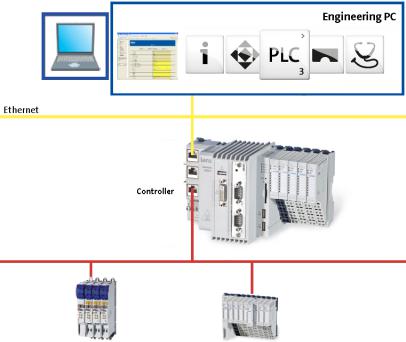
4 System structure
This chapter provides you with an overview of the basic system structure of the Lenze "Controllerbased Automation" system. The system consists of an Engineering PC, a Controller and the devices communicating with the Controller via the fieldbus.
[4-1] * The PROFIBUS fieldbus driver can only be accessed via PLC (Logic/Motion). Access via EASY Starter and VisiWinNET® Runtime is not provided.
Controllers and field devices form the automation system to be commissioned via the Engineering PC. The Engineering PC is a PC/Laptop with Windows® operating system and network connection. The Engineering PC comes installed with the Lenze Engineering tools ( 20) for parameter setting, configuration, programming and diagnostics.
The Controller with the PLC (Logic/Motion) is the central control section, consisting of the PLC runtime program (Runtime software of the Lenze Controllers ( 24)) with the running PLC application.
Device-internally, the Controller comes with a data manager for configuring and managing the data of the automation system. The data manager and the fieldbus driver enable the PLC (Logic/Motion) to access the system components and the field devices.
The fieldbus (Logic/Motion) enables the Controller to read and write the parameters of the connected field devices.
Lenze · Controller | Parameter setting & programming · Reference Manual · DMS 1.5 EN · 04/2014 · TD17 |
18 |

4 System structure
_ _ _ _ _ _ _ _ _ _ _ _ _ _ _ _ _ _ _ _ _ _ _ _ _ _ _ _ _ _ _ _ _ _ _ _ _ _ _ _ _ _ _ _ _ _ _ _ _ _ _ _ _ _ _ _ _ _ _ _ _ _ _ _
Note!
There is no OPC server available for PROFIBUS and PROFINET.
Controller c300/p300:
•The »EASY Starter« cannot be used for these devices (in preparation).
•The OPC communication for »VisiWinNET« is exclusively available for Controller p300 without PLC.
•Otherwise, only the Lenze "Logic&Motion" direct driver can be used for the data exchange between »VisiWinNET« and PLC.
19 |
Lenze · Controller | Parameter setting & programming · Reference Manual · DMS 1.5 EN · 04/2014 · TD17 |
4 System structure
4.1Engineering tools
_ _ _ _ _ _ _ _ _ _ _ _ _ _ _ _ _ _ _ _ _ _ _ _ _ _ _ _ _ _ _ _ _ _ _ _ _ _ _ _ _ _ _ _ _ _ _ _ _ _ _ _ _ _ _ _ _ _ _ _ _ _ _ _
4.1Engineering tools
The Engineering PC is a PC/Laptop with Windows® operating system and network connection.
The Engineering PC comes installed with the Lenze Engineering tools which enable the desired automation solution to be ...
•parameterised/configured;
•programmed;
•diagnosed.
Lenze · Controller | Parameter setting & programming · Reference Manual · DMS 1.5 EN · 04/2014 · TD17 |
20 |
4 System structure
4.1Engineering tools
_ _ _ _ _ _ _ _ _ _ _ _ _ _ _ _ _ _ _ _ _ _ _ _ _ _ _ _ _ _ _ _ _ _ _ _ _ _ _ _ _ _ _ _ _ _ _ _ _ _ _ _ _ _ _ _ _ _ _ _ _ _ _ _
 »EASY Navigator«: Starting the suitable Engineering tool
The Lenze Engineering software consists of the Engineering tools optimised for the respective Engineering phase.
The »EASY Navigator« shows the Lenze Engineering tools installed on the Engineering PC. Start the desired Engineering tool via the corresponding button:
The »EASY Navigator« ...
•simplifies the selection of the Engineering tool, depending on the Engineering phase.
•simplifies starting the desired Engineering tool (depending on the application case).
•makes it possible to select the Engineering tool suitable for the Engineering phase. The overview displays the respective function of the Engineering tools:
What would you like to do? |
Button |
Engineering tool |
Programming |
|
»PLC Designer« |
•Program the controller
•Parameterise/commission the Servo-Inverter i700
•Parameterise the I/O system 1000
Parameterising/configuring the inverter |
»EASY Starter« |
|
• Parameterise and configure the automation/drive |
|
|
system |
|
|
• Parameterise Inverter Drives 8400/Servo Drives 9400 |
|
|
|
|
|
Visualization |
»VisiWinNET« |
|
• Visualise the applications of the automation system |
|
|
• Create the visualisation/user interface |
|
|
|
|
|
Online diagnostics |
»EASY Starter« 1) |
|
• Easy online diagnostics of the Controllers (from»EASY |
(Reading parameters) |
|
Starter« V1.2) and other Lenze devices |
|
|
|
|
|
Online parameterisation |
»EASY Starter« 1) |
|
• Online parameterisation/commissioning of Lenze |
(Reading/writing |
|
devices |
parameters) |
|
• Direct online parameterisation with an active online |
|
|
connection to the Lenze devices |
|
|
|
|
|
Engineering tools that are not included in the »EASY Navigator«: |
|
|
Controller parameterisation/diagnostics |
|
»WebConfig« |
• »WebConfig« can be used on the controller without |
|
|
commissioning (integrated web server). |
|
|
• By the use of »WebConfig«, the parameters of the |
|
|
controller can be accessed via web browser. |
|
|
• »WebConfig« can also be started in the »PLC Designer«. |
|
|
|
|
|
Backup of controller data |
|
»Backup & Restore« |
• Create data backups |
|
|
• Restore data after device replacement |
|
|
• Carry out software update of the Controller |
|
|
1) For Controllers c300/p300 in preparation |
|
|
21 |
Lenze · Controller | Parameter setting & programming · Reference Manual · DMS 1.5 EN · 04/2014 · TD17 |

4 System structure
4.2Controller: The control centre of the Controller-based Automation
_ _ _ _ _ _ _ _ _ _ _ _ _ _ _ _ _ _ _ _ _ _ _ _ _ _ _ _ _ _ _ _ _ _ _ _ _ _ _ _ _ _ _ _ _ _ _ _ _ _ _ _ _ _ _ _ _ _ _ _ _ _ _ _
4.2Controller: The control centre of the Controller-based Automation
Cabinet controllers: Compact control cabinet design
Cabinet controllers are designed for the demanding continuous use in industrial applications. Compared to panel controllers, they are not equipped with an integrated display. The Controllers 3231 C and 3241 C are provided with a DVI interface for the connection of an external monitor panel.
Mounting is carried out in a control cabinet or a corresponding built-in housing on a standard DIN rail (35 mm). The device-internal backplane bus provides for a direct connection of the I/O system 1000.
Panel controllers: controlling and visualising
Panel controllers are designed for the installation into control cabinets, machine panels, or other mounting cutouts. They are equipped with rear bolts and clamping screws which provide for easy mounting and reliable sealing (front panel enclosure IP65/rear panel IP20) in rough industrial environments. They can be operated easily by directly touching the screen.
General features
•Controller programming, configuration and diagnostics using the »PLC Designer« (on the basis of CoDeSys 3.x)
•USB 2.0 interfaces and SD card slot, e.g. for data backup/restore»Backup & Restore« (data backup/restore) ( 67)
•4 LEDs for diagnostic purposes:
•Current supply
•Status of the PLC
•Status of the backplane bus
•Freely programmable LED
Operating instructions for the Controller
Here, further information on the device-specific properties can be found.
Lenze · Controller | Parameter setting & programming · Reference Manual · DMS 1.5 EN · 04/2014 · TD17 |
22 |

4 System structure
4.2Controller: The control centre of the Controller-based Automation
_ _ _ _ _ _ _ _ _ _ _ _ _ _ _ _ _ _ _ _ _ _ _ _ _ _ _ _ _ _ _ _ _ _ _ _ _ _ _ _ _ _ _ _ _ _ _ _ _ _ _ _ _ _ _ _ _ _ _ _ _ _ _ _
Fieldbus communication
The Lenze Controllers have different interfaces for fieldbus communication:
Area |
|
Cabinet Controller |
|
Panel Controller |
||
|
c300 |
3221 C |
3231 C |
3241 C |
p300 |
p500 |
Interfaces (on board) |
|
|
|
|
|
|
Ethernet |
1 |
|
2 |
|
1 |
2 |
EtherCAT |
1 1) |
|
1 |
|
1 1) |
1 |
CANopen |
1 2) |
|
- |
|
1 2) |
- |
Optional interfaces (communication cards) |
|
|
|
|
||
CANopen |
- |
|
|
|
- |
|
MC-CAN2 |
|
|
|
|
|
|
PROFIBUS master |
- |
|
|
|
- |
|
MC-PBM |
|
|
|
|
|
|
PROFIBUS slave |
- |
|
|
|
- |
|
MC-PBS |
|
|
|
|
|
|
PROFINET device |
- |
|
|
|
- |
|
MC-PND |
|
|
|
|
|
|
|
|
|
|
|
|
|
1)In preparation
2)Only the CAN master functionality is supported.
The Ethernet interface serves to connect the Engineering PC or to create line topologies (no integrated switch for Controller c300/p300).
More information on the bus systems and configuration can be found in the communication manuals:
•Controller-based Automation EtherCAT®
•Controller-based Automation CANopen®
•Controller-based Automation PROFIBUS®
•Controller-based Automation PROFINET®
23 |
Lenze · Controller | Parameter setting & programming · Reference Manual · DMS 1.5 EN · 04/2014 · TD17 |
4 System structure
4.3Runtime software of the Lenze Controllers
_ _ _ _ _ _ _ _ _ _ _ _ _ _ _ _ _ _ _ _ _ _ _ _ _ _ _ _ _ _ _ _ _ _ _ _ _ _ _ _ _ _ _ _ _ _ _ _ _ _ _ _ _ _ _ _ _ _ _ _ _ _ _ _
4.3Runtime software of the Lenze Controllers
By default, the runtime software is installed in the Lenze Controller as "Logic" mode for the central control of PLC applications.
Optionally, the "Motion" mode is available, additionally enabling extensive motion control of Motion functions. The inverter then only acts as an actuating drive.
In addition, the "Visu" mode is available, enabling a central visualisation with the Controller. The runtime software consists of:
•Operating system (Windows® CE)
•Software components (Logic/Motion), which for instance execute the control program.
•Optional visualisation software (»VisiWinNET« Compact CE).
Differences between "Logic" and "Motion"
Logic |
Motion |
|
|
The controller controls... |
The controller controls extensive motion sequences. |
• simple motion sequences; |
The runtime software "Motion" ... |
• by logically combined control signals. |
• contains the PLCopen library; |
|
• contains the "Logic" mode; |
|
• supports "SoftMotion". |
|
|
Logic applications are suitable for the control of inverters |
Motion applications are suitable... |
without a Motion functionality which ... |
• for the control of inverters executing complex motion |
• execute simple motion sequences; |
sequences of multi-axes in several dimensions; |
• can only be controlled via PLC functionality. |
• ...for the control of devices that are to traverse |
|
synchronously; |
|
• for the transfer of setpoints. |
Note!
Depending on the runtime software (Logic/Motion) used, a bus system for a Lenze device series can only be used in a limited way.
Details can be found in the communication manuals:
•Controller-based Automation EtherCAT®
•Controller-based Automation CANopen®
•Controller-based Automation PROFIBUS®
•Controller-based Automation PROFINET®
Lenze · Controller | Parameter setting & programming · Reference Manual · DMS 1.5 EN · 04/2014 · TD17 |
24 |
4 System structure
4.3Runtime software of the Lenze Controllers
_ _ _ _ _ _ _ _ _ _ _ _ _ _ _ _ _ _ _ _ _ _ _ _ _ _ _ _ _ _ _ _ _ _ _ _ _ _ _ _ _ _ _ _ _ _ _ _ _ _ _ _ _ _ _ _ _ _ _ _ _ _ _ _
4.3.1"Logic" runtime software
"Logic" refers to the use of logically combined control signals without Motion functions. When the "Logic" mode is used, the controller solely controls the motion sequences via logically combined control signals.
Functionality
•Programming PLC functionality according to IEC 61131-3.
•SoftPLC functionality for executing PLC programs.
•The multi-tasking Windows® CE operating system processes the PLC programs cyclically.
Performance
The "Logic" mode defines the program function. The performance of the entire automation system results from the interaction of the runtime software and the target system in each case. The system performance thus depends on the processor of the respective controller, and on other factors.
Engineering tool required: »PLC Designer«
4.3.2"Motion" runtime software
The "Motion" mode makes it possible to execute more complex motion sequences than with the Logic mode.
In the case of a Motion system, the whole motion control (Motion) of the axes to be controlled takes place in the controller. The higher-level controller generates the motion profiles for all Motion axes and transfers the data to the axes via EtherCAT.
A Motion-application...
•...makes special demands on the cycle time and real-time capability of the bus system between the controller and the connected field devices.
•for instance is to be used if the axes to be controlled are to be traversed in a synchronised manner or position setpoints are to be transmitted.
Functionality
•Motion functions according to PLCopen "Function blocks for Motion Control" version 2.0
•Contains the "Logic" runtime software for the use of logically combined control signals.
Additional functions
•Motion function blocks/libraries
•Supports programs for the control of complex motion sequences with several axes.
Engineering tool required: »PLC Designer«
25 |
Lenze · Controller | Parameter setting & programming · Reference Manual · DMS 1.5 EN · 04/2014 · TD17 |

4 System structure
4.3Runtime software of the Lenze Controllers
_ _ _ _ _ _ _ _ _ _ _ _ _ _ _ _ _ _ _ _ _ _ _ _ _ _ _ _ _ _ _ _ _ _ _ _ _ _ _ _ _ _ _ _ _ _ _ _ _ _ _ _ _ _ _ _ _ _ _ _ _ _ _ _
4.3.3"Visu" runtime software
The "Controller-based Automation" system enables the central visualisation of the automation system.
The visualisation can either run on a separate Controller or monitor panel or on the Controller on which the "Logic" or "Motion" runtime software is running.
Various options described in the following sections are available for the communication link.
Functionality
The "Visu" mode ...
•extends the Controller to a visualisation device;
•can be used separately or in addition to "Logic" or "Motion". Engineering tool required: »VisiWinNET«
Note!
There is no OPC server available for PROFIBUS and PROFINET.
Controller c300/p300:
•The OPC communication for »VisiWinNET« is exclusively available for Controller p300 without PLC.
•Otherwise, only the Lenze "Logic&Motion" direct driver can be used for the data exchange between »VisiWinNET« and PLC.
Lenze · Controller | Parameter setting & programming · Reference Manual · DMS 1.5 EN · 04/2014 · TD17 |
26 |
4 System structure
4.3Runtime software of the Lenze Controllers
_ _ _ _ _ _ _ _ _ _ _ _ _ _ _ _ _ _ _ _ _ _ _ _ _ _ _ _ _ _ _ _ _ _ _ _ _ _ _ _ _ _ _ _ _ _ _ _ _ _ _ _ _ _ _ _ _ _ _ _ _ _ _ _
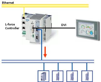
4.3.3.1Sample topology 1: External monitor panel/display for cabinet controllers
[4-2] Sample topology: Controller 3231 C with an external monitor panel (connected to the DVI interface)
This topology with regard to its performance corresponds to the implemented solution (control/ visualisation on the same controller). The external monitor panel/display shows the visualisation.
Advantages
•Small amount of cabling
•Protected operating conditions
•Extensible topology
•No impact on the real-time capability of the fieldbus by the visualisation
27 |
Lenze · Controller | Parameter setting & programming · Reference Manual · DMS 1.5 EN · 04/2014 · TD17 |
4 System structure
4.3Runtime software of the Lenze Controllers
_ _ _ _ _ _ _ _ _ _ _ _ _ _ _ _ _ _ _ _ _ _ _ _ _ _ _ _ _ _ _ _ _ _ _ _ _ _ _ _ _ _ _ _ _ _ _ _ _ _ _ _ _ _ _ _ _ _ _ _ _ _ _ _
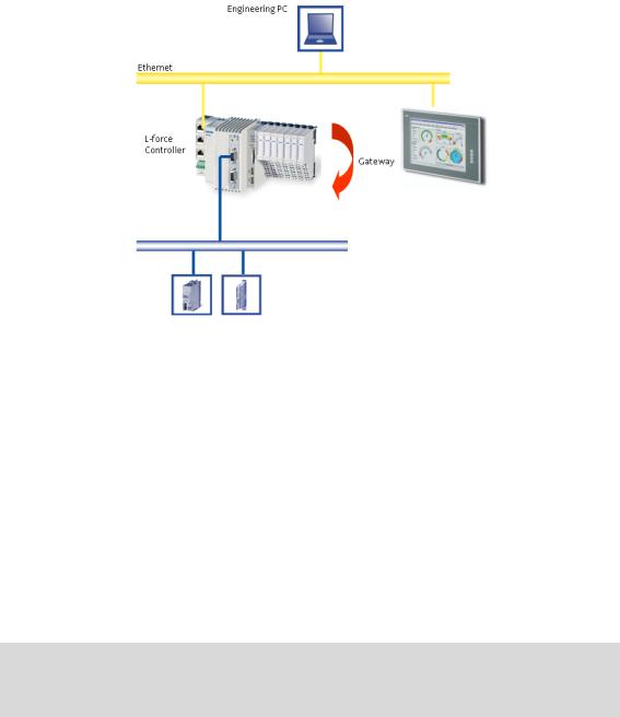
4.3.3.2Sample topology 2: Separate control and visualisation
[4-3] Sample topology: Controller 3200 C as gateway for the Visualisation Controller (IPC)
The Visualisation Controller (IPC) accesses the field devices via the Controller 3200 C as gateway.
In order to separate the control and visualisation, the integrated gateway function of the controller can be used.
The use of this topology is advisable...
•to achieve a higher performance;
•for the use of different operating systems within one automation system. Engineering tools required: »EASY Starter«, »Engineer«
Advantages
•No impact on the real-time capability of the fieldbus by the visualisation.
•Several visualisations can access the controller.
•Most suitable for extensive visualisation processes.
Note!
In case of Controller c300/p300, the gateway function is not supported (in preparation).
Lenze · Controller | Parameter setting & programming · Reference Manual · DMS 1.5 EN · 04/2014 · TD17 |
28 |
4 System structure
4.3Runtime software of the Lenze Controllers
_ _ _ _ _ _ _ _ _ _ _ _ _ _ _ _ _ _ _ _ _ _ _ _ _ _ _ _ _ _ _ _ _ _ _ _ _ _ _ _ _ _ _ _ _ _ _ _ _ _ _ _ _ _ _ _ _ _ _ _ _ _ _ _
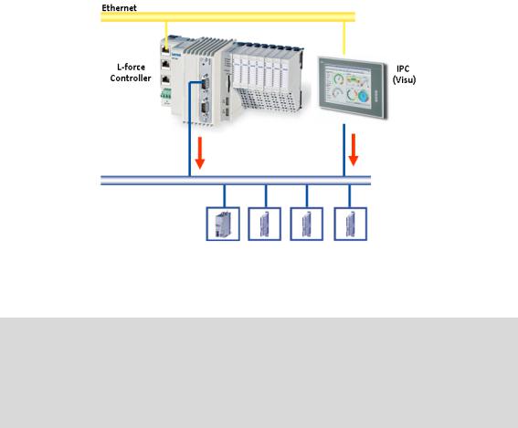
4.3.3.3Sample topology 3: Independent control and visualisation (CANopen)
[4-4] Sample configuration: Parallel access of Controller 3200 C and Visualisation Controller (IPC)
If this topology is used, the Controller 3200 C and the Visualisation Controller (IPC) access the fieldbus independently of each other.
Note!
The configuration with a control and configuration independent of each other is only available for the CANopen bus system!
•CANopen enables (several) fieldbus master independent of each other.
•In connection with EtherCAT, no configuration with two fieldbus masters is possible.
Advantages
•Spatially separate control and visualisation.
•The visualisation has access to the parameters of the field devices.
Disadvantage
•The visualisation may disrupt the real-time capability of the fieldbus. This topology therefore is only suitable for Motion systems to a limited extent (depending on the bus system used).
29 |
Lenze · Controller | Parameter setting & programming · Reference Manual · DMS 1.5 EN · 04/2014 · TD17 |

5 Commissioning the controller
_ _ _ _ _ _ _ _ _ _ _ _ _ _ _ _ _ _ _ _ _ _ _ _ _ _ _ _ _ _ _ _ _ _ _ _ _ _ _ _ _ _ _ _ _ _ _ _ _ _ _ _ _ _ _ _ _ _ _ _ _ _ _ _
5 Commissioning the controller
This chapter provides some general information on the commissioning of a controller. Depending on the actual hardware installed, different settings are required for integrating the controller into a network.
Note!
Please observe the predefined IP address of the controller for the initial commissioning: 192.168.5.99 (Lenze setting).
Further information on how to set the IP address of the Controller can be found here:Entering the IP address of the controller ( 33)
Read the mounting instructions supplied before you start working!
The mounting instructions contains safety instructions which must be observed!
Operating instructions for the Controller
Here, further information on the device-specific properties can be found.
Lenze · Controller | Parameter setting & programming · Reference Manual · DMS 1.5 EN · 04/2014 · TD17 |
30 |
Loading...