


smd Series Drives
Modbus Communications Reference Guide

About These Instructions
This documentation applies to the use of an smd Series Variable Frequency Drive in a Modbus Network and should be used in conjunction with the smd Series Operating Instructions (Document SL03) that shipped with the drive. These documents should be read in their entirety as they contain important technical data and describe the installation and operation of the drive.
Modbus® and Modicon® are registered trademarks of Schneider Electric; http://www.schneider-electric.com.
For more information about the Modbus Protocol please refer to the Modicon Modbus Protocol Reference Guide; http://www.Modbus.org
© 2003 AC Technology Corporation
No part of this documentation may be copied or made available to third parties without the explicit written approval of AC Technology Corporation. All information given in this documentation has been carefully selected and tested for compliance with the hardware and software described. Nevertheless, discrepancies cannot be ruled out. AC Tech does not accept any responsibility nor liability for damages that may occur. Any necessary corrections will be implemented in subsequent editions.

|
|
|
Contents |
|
1 |
Safety Information.............................................................................................................. |
1 |
||
|
1.1 |
Warnings, Cautions and Notes............................................................................... |
1 |
|
|
|
1.1.1 |
General..................................................................................................... |
1 |
|
|
1.1.2 |
Application................................................................................................ |
1 |
|
|
1.1.3 |
Installation................................................................................................ |
1 |
|
|
1.1.4 |
Electrical Connection................................................................................ |
2 |
|
|
1.1.5 |
Operation.................................................................................................. |
2 |
|
1.2 |
Reference and Links.............................................................................................. |
2 |
|
2 |
Introduction....................................................................................................................... |
|
3 |
|
|
2.1 |
RS485 Details....................................................................................................... |
3 |
|
|
2.2 |
Electrical Installation............................................................................................. |
3 |
|
|
|
2.2.1 |
Cable Type................................................................................................ |
3 |
|
|
2.2.2 |
Connections and Shielding........................................................................ |
3 |
|
|
2.2.3 |
Network Termination................................................................................ |
4 |
|
2.3 |
Modbus Details..................................................................................................... |
4 |
|
|
2.4 |
Universal Registers................................................................................................ |
6 |
|
3 Data Representation - Internal and External....................................................................... |
7 |
|||
|
3.1 |
Register Format..................................................................................................... |
7 |
|
|
3.2 |
Data Types............................................................................................................ |
7 |
|
|
3.3 |
smd Drive Registers.............................................................................................. |
7 |
|
4 smd Drive Setup & Operation............................................................................................. |
8 |
|||
|
4.1 |
Control Parameter................................................................................................. |
8 |
|
|
4.2 |
Serial Address....................................................................................................... |
8 |
|
|
4.3 |
Serial Communications Parameter......................................................................... |
8 |
|
|
4.4 |
Watchdog Timer.................................................................................................... |
9 |
|
|
4.5 |
Unlocking & Locking Controls................................................................................ |
10 |
|
|
4.6 |
Unlocking & Locking Programming Parameters only.............................................. |
10 |
|
|
4.7 |
Monitoring Only Operation..................................................................................... |
10 |
|
|
4.8 |
Normal Control Operation Sequence...................................................................... |
11 |
|
|
4.9 |
Start/Stop, Speed Control and Parameter Change Operation.................................. |
11 |
|
i |
RG-SDMOD |

Contents
5 smd Drive Control Registers............................................................................................... |
12 |
|||
|
5.1 |
Abbreviations........................................................................................................ |
13 |
|
|
5.2 |
Drive Control - Register #1.................................................................................... |
13 |
|
|
5.3 |
Drive Hardware Configuration - Register #22......................................................... |
14 |
|
|
5.4 |
Drive Status - Registers #24-29............................................................................ |
15 |
|
|
|
5.4.1 |
Reading Register #24 ............................................................................... |
15 |
|
|
5.4.2 |
Operational Status - Register #26 ............................................................. |
16 |
|
|
5.4.3 Actual Rotational Direction - Registers #24 & 27....................................... |
16 |
|
|
|
5.4.4 Control Mode - Registers #24 & 27........................................................... |
16 |
|
|
|
5.4.5 Speed Command Source - Registers #24 & 28......................................... |
17 |
|
|
|
5.4.6 Speed Reference Status - Registers #24 & 28........................................... |
17 |
|
|
|
5.4.7 Present Fault - Registers #24 & 29........................................................... |
17 |
|
|
|
5.4.8 Commanded Rotational Direction - Registers #24 & 29............................. |
18 |
|
|
5.5 |
Motor Volts - Register #30..................................................................................... |
18 |
|
|
5.6 |
Serial Speed - Register #40................................................................................... |
18 |
|
|
5.7 |
Unlock Commands - Register #48......................................................................... |
18 |
|
|
5.8 |
Unlock Parameters - Register #49......................................................................... |
18 |
|
|
5.9 |
Register Version.................................................................................................... |
18 |
|
6 |
smd Programming Parameters........................................................................................... |
19 |
||
|
6.1 |
Format |
.................................................................................................................. |
19 |
|
6.2 |
Parameter .......................................................................................................List |
20 |
|
7 |
Quick Start Instructions...................................................................................................... |
25 |
||
|
7.1 |
Initial Settings....................................................................................................... |
25 |
|
|
7.2 |
Drive Control......................................................................................................... |
26 |
|
|
7.3 |
Basic Drive .........................................................................................Commands |
26 |
|
|
7.4 |
Basic Drive .................................................................................................Status |
27 |
|
RG-SDMOD |
ii |

Safety Information
1 Safety Information
1.1Warnings, Cautions and Notes
1.1.1General
Some parts of Lenze controllers (frequency inverters, servo inverters, DC controllers) can be live, moving and rotating. Some surfaces can be hot.
Non-authorized removal of the required cover, inappropriate use, and incorrect installation or operation creates the risk of severe injury to personnel or damage to equipment.
All operations concerning transport, installation, and commissioning as well as maintenance must be carried out by qualified, skilled personnel (IEC 364 and CENELEC HD 384 or DIN VDE 0100 and IEC report 664 or DIN VDE0110 and national regulations for the prevention of accidents must be observed).
According to this basic safety information, qualified skilled personnel are persons who are familiar with the installation, assembly, commissioning, and operation of the product and who have the qualifications necessary for their occupation.
1.1.2Application
Drive controllers are components designed for installation in electrical systems or machinery. They are not to be used as appliances. They are intended exclusively for professional and commercial purposes according to EN 61000-3-2. The documentation includes information on compliance with EN 61000-3-2.
When installing the drive controllers in machines, commissioning (i.e. the starting of operation as directed) is prohibited until it is proven that the machine complies with the regulations of the EC Directive 98/37/EC (Machinery Directive); EN 60204 must be observed.
Commissioning (i.e. starting drive as directed) is only allowed when there is compliance to the EMC Directive (89/336/EEC).
The drive controllers meet the requirements of the Low Voltage Directive 73/23/EEC. The harmonised standards of the series EN 50178/DIN VDE 0160 apply to the controllers.
The availability of controllers is restricted according to EN 61800-3. These products can cause radio interference in residential areas. In the case of radio interference, special measures may be necessary for drive controllers.
1.1.3Installation
Ensure proper handling and avoid excessive mechanical stress. Do not bend any components and do not change any insulation distances during transport or handling. Do not touch any electronic components and contacts. Controllers contain electrostatically sensitive components, which can easily be damaged by inappropriate handling. Do not damage or destroy any electrical components since this might endanger your health! When installing the drive ensure optimal airflow by observing all clearance distances in the drive's user manual. Do not expose the drive to excessive: vibration, temperature, humidity, sunlight, dust, pollutants, corrosive chemicals or other hazardous environments.
1 |
RG-SDMOD |
Safety Information
1.1.4Electrical Connection
When working on live drive controllers, applicable national regulations for the prevention of accidents (e.g. VBG 4) must be observed.
The electrical installation must be carried out in accordance with the appropriate regulations (e.g. cable cross-sections, fuses, PE connection). Additional information can be obtained from the regulatory documentation.
The regulatory documentation contains information about installation in compliance with EMC (shielding, grounding, filters and cables). These notes must also be observed for CE-marked controllers.
The manufacturer of the system or machine is responsible for compliance with the required limit values demanded by EMC legislation.
1.1.5Operation
Systems including controllers must be equipped with additional monitoring and protection devices according to the corresponding standards (e.g. technical equipment, regulations for prevention of accidents, etc.). You are allowed to adapt the controller to your application as described in the documentation.
DANGER!
•After the controller has been disconnected from the supply voltage, do not touch the live components and power connection until the capacitors have discharged. Please observe the corresponding notes on the controller.
•Do not continuously cycle input power to the controller more than once every three minutes.
•Close all protective covers and doors during operation.
WARNING!
Network control permits automatic starting and stopping of the inverter drive. The system design must incorporate adequate protection to prevent personnel from accessing moving equipment while power is applied to the drive system.
Table 1: Pictographs used in these instructions
|
Pictograph |
Signal word |
Meaning |
Consequences if ignored |
|
|
|
|
|
|
|
|
|
|
DANGER! |
Warning of Hazardous Electrical |
Reference to an imminent danger that may |
|
|
|
|
Voltage. |
result in death or serious personal injury if the |
|
|
|
|
|
corresponding measures are not taken. |
|
|
|
|
|
|
|
|
|
WARNING! |
Impending or possible danger |
Death or injury |
|
|
|
|
for persons |
|
|
|
|
|
|
|
|
|
|
STOP! |
Possible damage to equipment |
Damage to drive system or its surroundings |
|
|
|
|
|
|
|
|
|
NOTE |
Useful tip: If observed, it will |
|
|
|
|
|
||
|
|
|
|
make using the drive easier |
|
|
|
|
|
|
|
|
|
|
|
|
|
1.2Reference and Links
smd Series Variable Frequency Drives visit: http://www.lenze-actech.com
Modbus-IDA visit: http://www.modbus.org |
|
RG-SDMOD |
2 |

Introduction
2 Introduction
This document defines the specifics required for Modbus serial communication with a Lenze-AC Tech standard smd Series drive for control, status monitoring, and programming parameters. A familiarity with normal drive capabilities and operations is assumed. If this is not the case, refer to the smd Series Operating Instructions (SL03) for more information.
2.1RS485 Details
Only standard smd models with an “L” as the eighth digit in the model number (ex. ESMD371L4TXA) are equipped with Modbus RS-485 capabilities. When using this feature the drive can communicate with a personal computer (PC), programmable logic controller (PLC), or other external device that utilizes Modbus RS-485 serial communication for control or monitoring. Refer to the smd Operating Instructions (SL03) for connection details. Figure 1 illustrates the smd control strip. Terminals 7 (COM), 71 (TXB) and 72 (TXA) are used for RS485 communication.
|
|
|
|
|
L1 L2 L3 |
|
|
|
|
COM |
|
TXB TXA |
COM |
AIN |
+10 V |
+12 V |
|
71 72 |
7 |
8 |
9 |
20 28 E1 E2 E3 20 A1 62 K14 K12 |
U V W |
Figure 1: smd Control Strip
2.2Electrical Installation
2.2.1Cable Type
For RS485 Modbus networks, use a quality shielded twisted pair cable. The use of low quality cable will result in excess signal attenuation and data loss.
2.2.2Connections and Shielding
To ensure good system noise immunity all networks cables should be correctly grounded:
•Minimum grounding recommendation: ground the network cable shield once in every cubical.
•Ideal grounding recommendation: ground the network cable on or as near to each drive as possible.
•For wiring of cable to the smd control terminal, the unscreened cable cores should be kept as short as possible; recommended maximum of 20mm. Ground the shield at the drive end only.
•In addition, grounding terminal 7 on the smd is recommended when using serial communications.
|
|
|
|
|
L1 L2 L3 |
|
|
|
|
COM |
|
TXB TXA |
COM |
AIN |
+10 V |
+12 V |
|
71 72 |
7 |
8 |
9 |
20 28 E1 E2 E3 20 A1 62 K14 K12 |
U V W |
20mm |
Connect to |
max |
drive earth |
|
(PE) |
Figure 2: Connector Wiring Diagram
3 |
RG-SDMOD |
Introduction
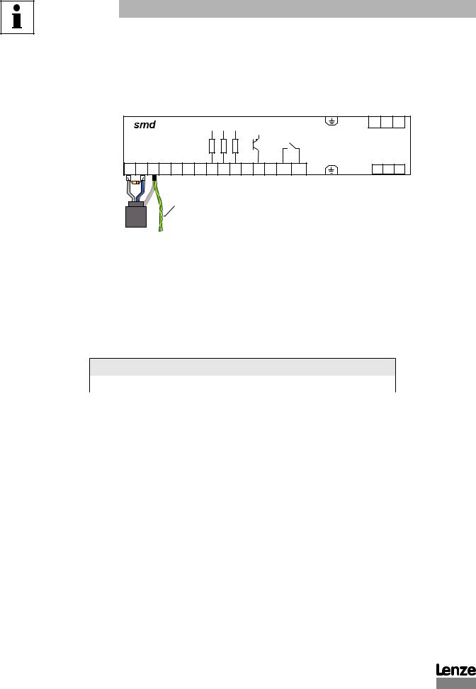
2.2.3Network Termination
For an RS-485 network it is essential to install the specified termination resistors (120W), i.e. one at both ends of a network segment. Failure to do so will result in signals being reflected back along the cable which will cause data corruption. An external 120W 1/4W resistor can be connected as shown in Figure 3.
|
|
|
|
|
L1 L2 L3 |
|
|
|
|
COM |
|
TXB TXA |
COM |
AIN |
+10 V |
+12 V |
|
71 72 |
7 |
8 |
9 |
20 28 E1 E2 E3 20 A1 62 K14 K12 |
U V W |
120Ω |
Connect to |
1/4W |
drive earth |
|
(PE) |
Figure 3: Network Termination Resistor
2.3Modbus Details
A.smd Drives running the Modbus communication protocol use the RTU (Remote Terminal Unit) transmission mode and are slaves only. Therefore, the device communicating with the drives must be a Modbus Master. The baud rate is 9600. The default setting is no parity (two stop bits). There are provisions for: No parity, 1 stop bit (PV507); Odd parity, 1 stop bit; and Even parity 1 stop bit as well. The bit sequence is:
DATA
Start bit |
1 |
2 |
3 |
4 |
5 |
6 |
7 |
8 |
Stop bit |
Stop bit |
|
|
|
|
|
|
|
|
|
|
|
B.At this time the smd drive does not support the broadcast function of the protocol.
C.IMPORTANT NOTE: Modbus 3X and 4X Registers are numbered starting at 1. However, when transmitted to a slave over the serial link, the actual address transmitted is one less. This is because the addresses are numbered starting from 0. The smd register numbers are also numbered starting from 0. Therefore, smd register numbers always correspond exactly with the address transmitted. As a result, MODBUS REGISTER NUMBERS ARE ALWAYS ONE GREATER THAN smd REGISTER NUMBERS. WHENEVER THE WORDS “REGISTER #xx” APPEAR, IT SHOULD BE ASSUMED THAT THEY MEAN “smd REGISTER xx” and the Modbus Register number will be one larger. In some instances we may show both for clarity. For example: “Register #24 (Modbus Register #25) . . .”
RG-SDMOD |
4 |

Introduction
D. The function codes supported by the smd drives are:
03Read Holding Register (4X references). In general we can read only one register at a time. However, there are a few limited exceptions.
Exception One:
Register #24 (Modbus Register #25) Drive Status, can also be read as a group of 6 words.
Exception Two:
Parameter C99 (Software Version) is a 4-word read.
04Read Input Register (3X references). As with function 03, we read one register at a time except where noted.
06 Preset Single Register (4X references). Write single register.
16Preset Multiple Registers (4X references). Although the function is for multiple registers, we will accept only a single register to be written.
Note: Since we do not differentiate between 4X and 3X references, function codes 03 and 04 are treated identically.
E.Exception codes:
01 - Command rejected, Illegal function
02 - No such register
03 - Data out of range
04 - Wrong data format
06 - Slave device busy
F.The smd drive will most nearly conform to the Modicon® Micro 84 in capabilities. This may be of importance when configuring networks for DDE Servers.
G.Modbus® and Modicon® are registered trademarks of Schneider Electric. For more information about the Modbus Protocol please refer to the Modicon Modbus Protocol Reference Guide. Web resources: http://www.Modbus-IDA.org and http://www.schneider-electric.com.
5 |
RG-SDMOD |

Introduction
2.4Universal Registers
Lenze-AC Tech manufactures several drive families. Currently the QC, MC, MCH, SC, TC, smd, Tmd and SMV Series drives support Modbus based communications. Since each drive family has different parameters and size ranges, the parameter (register) definitions are in many cases quite different. In order to facilitate communication in a network with a mix of drive types, certain Lenze-AC Tech Register locations have been made universal among Lenze-AC Tech drives. While their locations are consistent, their contents may vary as defined in Table 2.
|
|
Table 2: Contents of Universal Registers |
||||
|
|
|
|
|
|
|
smd Reg # |
Function |
|
|
|
|
|
|
|
|
|
|
||
1 |
Drive Control (WRITE ONLY). Not all drives will have all control functions but when the function is |
|||||
|
available it will be at a defined bit location within Register #1. Drive Family and register Configuration |
|||||
|
Number dependent. |
|
|
|||
|
|
|
|
|
||
19 |
Drive Family (READ ONLY) This register is consistent among all Lenze-AC Tech drives: |
|||||
|
|
|
|
|
|
|
|
- 64 -- QC family |
|
- 67 -- |
|
- 70 -- TC family |
|
|
|
|
|
|
|
|
|
- 65 -- MC family |
|
- 68 -- MCH family |
|
- 71 -- Tmd family |
|
|
|
|
|
|
|
|
|
- 66 -- SC family |
|
- 69 -- smd family |
|
- 72 -- SMV family |
|
|
|
|
|
|
||
21 |
Drive Size (READ ONLY). Code to identify Power (HP/KW) and Line Voltage of the drive. Family |
|||||
|
dependent. For the smd series it always reads zero. |
|
|
|||
|
|
|||||
24 |
Drive Status (READ ONLY). Various operational variables. |
|||||
|
|
|
|
|||
48 |
Unlock Control (WRITE ONLY). |
|
|
|||
|
|
|
|
|||
49 |
Unlock Writing of registers (WRITE ONLY). |
|
|
|||
|
|
|
|
|||
50 |
Parameter Configuration Number (READ ONLY). |
|
|
|||
|
|
|
|
|
|
|
RG-SDMOD |
6 |
 Loading...