


TCF Series
Installation and Operation Manual
Table of Contents
1 |
GENERAL. . . . . . . . . . . . . . . . . . . . . . . . . . . . . . . . . . . . . . . . . . . . . . . . . . . . . . . . . . . . . . . . . . . . . . . . . . . . |
. 1 |
|
|
1..1 |
PRODUCTS COVERED IN THIS MANUAL.. . . . . . . . . . . . . . . . . . . . . . . . . . . . . . . . . . . . . . . . . . |
. 1 |
|
1..2 |
PRODUCT CHANGES.. . . . . . . . . . . . . . . . . . . . . . . . . . . . . . . . . . . . . . . . . . . . . . . . . . . . . . . . . . |
. 1 |
|
1..3 |
WARRANTY.. . . . . . . . . . . . . . . . . . . . . . . . . . . . . . . . . . . . . . . . . . . . . . . . . . . . . . . . . . . . . . . . . . |
. 1 |
|
1..4 |
RECEIVING. . . . . . . . . . . . . . . . . . . . . . . . . . . . . . . . . . . . . . . . . . . . . . . . . . . . . . . . . . . . . . . . . . . |
. 1 |
|
1..5 |
SAFETY INFORMATION.. . . . . . . . . . . . . . . . . . . . . . . . . . . . . . . . . . . . . . . . . . . . . . . . . . . . . . . . |
. 1 |
|
1..6 |
CUSTOMER MODIFICATION. . . . . . . . . . . . . . . . . . . . . . . . . . . . . . . . . . . . . . . . . . . . . . . . . . . . . |
. 2 |
2 |
TCF DIMENSIONS.. . . . . . . . . . . . . . . . . . . . . . . . . . . . . . . . . . . . . . . . . . . . . . . . . . . . . . . . . . . . . . . . . . . . . |
. 3 |
|
3 |
TCF MODEL DESIGNATION CODE. . . . . . . . . . . . . . . . . . . . . . . . . . . . . . . . . . . . . . . . . . . . . . . . . . . . . . . . |
. 5 |
|
4 |
TCF SPECIFICATIONS. . . . . . . . . . . . . . . . . . . . . . . . . . . . . . . . . . . . . . . . . . . . . . . . . . . . . . . . . . . . . . . . . . |
. 6 |
|
5 |
TCF RATINGS. . . . . . . . . . . . . . . . . . . . . . . . . . . . . . . . . . . . . . . . . . . . . . . . . . . . . . . . . . . . . . . . . . . . . . . . . |
. 7 |
|
6 |
INSTALLATION . . . . . . . . . . . . . . . . . . . . . . . . . . . . . . . . . . . . . . . . . . . . . . . . . . . . . . . . . . . . . . . . . . . . . . . . |
. 9 |
|
|
6..1 |
INSTALLATION AFTER A LONG PERIOD OF STORAGE.. . . . . . . . . . . . . . . . . . . . . . . . . . . . . . |
10 |
|
6..2 |
EXPLOSION PROOF APPLICATIONS. . . . . . . . . . . . . . . . . . . . . . . . . . . . . . . . . . . . . . . . . . . . . . |
10 |
7 |
INPUT AC POWER REQUIREMENTS . . . . . . . . . . . . . . . . . . . . . . . . . . . . . . . . . . . . . . . . . . . . . . . . . . . . . . |
11 |
|
|
7..1 |
INPUT VOLTAGE RATINGS. . . . . . . . . . . . . . . . . . . . . . . . . . . . . . . . . . . . . . . . . . . . . . . . . . . . . . |
11 |
|
7..2 |
INPUT FUSING & DISCONNECT REQUIREMENTS . . . . . . . . . . . . . . . . . . . . . . . . . . . . . . . . . . . |
12 |
|
7..3 |
INPUT WIRE SIZE REQUIREMENTS.. . . . . . . . . . . . . . . . . . . . . . . . . . . . . . . . . . . . . . . . . . . . . . |
13 |
|
7..4 |
INSTALLATION ACCORDING TO EMC REQUIREMENTS . . . . . . . . . . . . . . . . . . . . . . . . . . . . . . |
13 |
8 |
POWER WIRING. . . . . . . . . . . . . . . . . . . . . . . . . . . . . . . . . . . . . . . . . . . . . . . . . . . . . . . . . . . . . . . . . . . . . . . |
14 |
|
|
8..1 |
WIRING FOR SINGLE PHASE OR THREE PHASE INPUT. . . . . . . . . . . . . . . . . . . . . . . . . . . . . . |
14 |
9 |
TCF POWER WIRING DIAGRAM . . . . . . . . . . . . . . . . . . . . . . . . . . . . . . . . . . . . . . . . . . . . . . . . . . . . . . . . . . |
15 |
|
10 |
CONTROL WIRING. . . . . . . . . . . . . . . . . . . . . . . . . . . . . . . . . . . . . . . . . . . . . . . . . . . . . . . . . . . . . . . . . . . . . |
16 |
|
|
10..1 |
CONTROL WIRING VS. POWER WIRING. . . . . . . . . . . . . . . . . . . . . . . . . . . . . . . . . . . . . . . . . . . |
16 |
|
10..2 |
TB-2 AND TB-4 . . . . . . . . . . . . . . . . . . . . . . . . . . . . . . . . . . . . . . . . . . . . . . . . . . . . . . . . . . . . . . . . |
16 |
|
10..3 |
SURGE SUPPRESSION ON RELAYS . . . . . . . . . . . . . . . . . . . . . . . . . . . . . . . . . . . . . . . . . . . . . . |
16 |
|
10..4 |
START/STOP CONTROL . . . . . . . . . . . . . . . . . . . . . . . . . . . . . . . . . . . . . . . . . . . . . . . . . . . . . . . . |
16 |
|
10..5 |
SPEED/TORQUE REFERENCE SIGNALS.. . . . . . . . . . . . . . . . . . . . . . . . . . . . . . . . . . . . . . . . . . |
17 |
|
10..6 |
SPEED REFERENCE SELECTION.. . . . . . . . . . . . . . . . . . . . . . . . . . . . . . . . . . . . . . . . . . . . . . . . |
17 |
|
10..7 |
ANALOG OUTPUT SIGNALS . . . . . . . . . . . . . . . . . . . . . . . . . . . . . . . . . . . . . . . . . . . . . . . . . . . . . |
19 |
|
10..8 |
DRIVE STATUS DIGITAL OUTPUTS . . . . . . . . . . . . . . . . . . . . . . . . . . . . . . . . . . . . . . . . . . . . . . . |
19 |
11 |
TCF CONTROL WIRING DIAGRAMS. . . . . . . . . . . . . . . . . . . . . . . . . . . . . . . . . . . . . . . . . . . . . . . . . . . . . . . |
20 |
|
|
11..1 |
TCF TERMINAL STRIP. . . . . . . . . . . . . . . . . . . . . . . . . . . . . . . . . . . . . . . . . . . . . . . . . . . . . . . . . . |
20 |
|
11..2 |
TWO-WIRE START/STOP CONTROL . . . . . . . . . . . . . . . . . . . . . . . . . . . . . . . . . . . . . . . . . . . . . . |
21 |
|
11..3 |
ALTERNATE TWO-WIRE START/STOP CONTROL . . . . . . . . . . . . . . . . . . . . . . . . . . . . . . . . . . . |
22 |
|
11..4 |
THREE-WIRE START/STOP CONTROL. . . . . . . . . . . . . . . . . . . . . . . . . . . . . . . . . . . . . . . . . . . . |
23 |
|
11..5 |
SPEED POT AND PRESET SPEED CONTROL.. . . . . . . . . . . . . . . . . . . . . . . . . . . . . . . . . . . . . . |
24 |
|
11..6 |
BIPOLAR SPEED CONTRO L (-10 to +10 VDC).. . . . . . . . . . . . . . . . . . . . . . . . . . . . . . . . . . . . . . |
25 |
12 |
INITIAL POWER UP AND MOTOR ROTATION . . . . . . . . . . . . . . . . . . . . . . . . . . . . . . . . . . . . . . . . . . . . . . . |
26 |
|
13 |
PROGRAMMING THE TCF DRIVE. . . . . . . . . . . . . . . . . . . . . . . . . . . . . . . . . . . . . . . . . . . . . . . . . . . . . . . . . |
28 |
|
|
13..1 |
ELECTRONIC PROGRAMMING MODULE (EPM). . . . . . . . . . . . . . . . . . . . . . . . . . . . . . . . . . . . . |
29 |
|
13..2 |
TCF DRIVE PERSONALITY . . . . . . . . . . . . . . . . . . . . . . . . . . . . . . . . . . . . . . . . . . . . . . . . . . . . . . |
31 |
14 |
PARAMETER MENU. . . . . . . . . . . . . . . . . . . . . . . . . . . . . . . . . . . . . . . . . . . . . . . . . . . . . . . . . . . . . . . . . . . . |
32 |
|
15 |
DESCRIPTION OF PARAMETERS.. . . . . . . . . . . . . . . . . . . . . . . . . . . . . . . . . . . . . . . . . . . . . . . . . . . . . . . . |
36 |
|
16 |
TROUBLESHOOTING . . . . . . . . . . . . . . . . . . . . . . . . . . . . . . . . . . . . . . . . . . . . . . . . . . . . . . . . . . . . . . . . . . |
57 |
|
17 |
TCF DISPLAY MESSAGES . . . . . . . . . . . . . . . . . . . . . . . . . . . . . . . . . . . . . . . . . . . . . . . . . . . . . . . . . . . . . . |
59 |
|
|
17..1 |
SPEED/TORQUE DISPLAY.. . . . . . . . . . . . . . . . . . . . . . . . . . . . . . . . . . . . . . . . . . . . . . . . . . . . . . |
59 |
|
17..2 |
CHANGING THE SPEED REFERENCE SOURCE.. . . . . . . . . . . . . . . . . . . . . . . . . . . . . . . . . . . . |
60 |
|
17..3 |
STATUS AND WARNING MESSAGES.. . . . . . . . . . . . . . . . . . . . . . . . . . . . . . . . . . . . . . . . . . . . . |
61 |
A |
APPENDIX - VECTOR MODE. . . . . . . . . . . . . . . . . . . . . . . . . . . . . . . . . . . . . . . . . . . . . . . . . . . . . . . . . . . . . |
62 |
|
B |
APPENDIX - INPUT ASSERTION LEVEL. . . . . . . . . . . . . . . . . . . . . . . . . . . . . . . . . . . . . . . . . . . . . . . . . . . . |
64 |
|
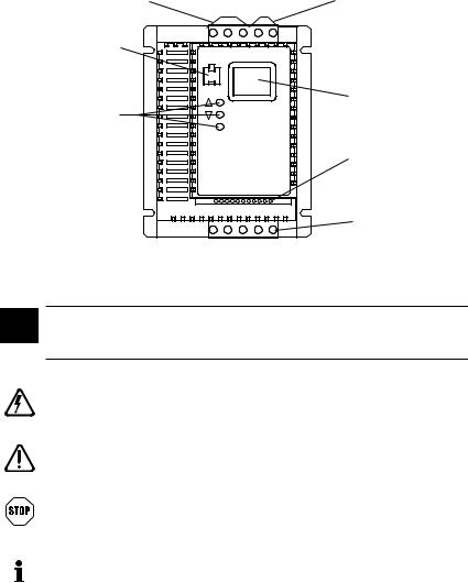
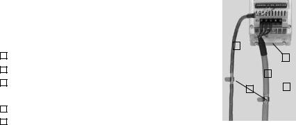
TCF Sub-Micro Drive
INPUT POWER |
DC BUS |
|
TERMINALS |
TERMINALS |
|
ELECTRONIC |
|
|
PROGRAMMING |
|
|
MODULE (EPM) |
|
|
PROGRAMMING |
3-DIGIT LED |
|
DISPLAY |
||
BUTTONS |
||
|
||
|
CONTROL |
|
|
TERMINAL |
|
|
STRIP |
|
|
OUTPUT |
|
|
(MOTOR) |
|
|
TERMINALS |
Safety Information
All safety information given in these Operating Instruction have the same layout:
Signal Word! (Characterizes the severity of the danger)
Note (describes the danger and informs on how to proceed)
|
|
|
Icon |
Signal Words |
|
|
|
|
|
|
|
|
|
|
Warning of |
DANGER! |
Warns of impending danger.. |
|
|
|
hazardous |
|
Consequences if disregarded: |
|
|
|
electrical |
|
Death or severe injuries.. |
|
|
|
voltage |
|
|
|
|
|
|
|
|
|
|
|
Warning of a |
WARNING! |
Warns of potential, very hazardous situations.. |
|
|
|
general danger |
|
Consequences if disregarded: |
|
|
|
|
|
Death or severe injuries.. |
|
|
|
|
|
|
|
|
|
Warning of |
STOP! |
Warns of potential damage to material and |
|
|
|
damage to |
|
equipment.. |
|
|
|
equipment |
|
Consequences if disregarded: |
|
|
|
|
|
Damage to the controller/drive or its environment.. |
|
|
|
|
|
|
|
|
|
Information |
Note |
Designates a general, useful note.. |
|
|
|
|||
|
|
|
|
|
If you observe it, handling the controller/drive system is |
|
|
|
|
|
made easier.. |
|
|
|
|
|
|
|
|
|
|
|
|
1GENERAL
1..1 PRODUCTS COVERED IN THIS MANUAL
This manual covers the Lenze AC Tech TCF Series Variable Frequency Drive..
1..2 PRODUCT CHANGES
Lenze AC Tech Corporation reserves the right to discontinue or make modifications to the design of its products without prior notice, and holds no obligation to make modifications to products sold previously. Lenze AC Tech also holds no liability for losses of any kind which may result from this action. Instruction manuals with the most up-to-date information are available for download from the Lenze AC Tech web site (www..lenzeamericas..com)..
1..3 WARRANTY
Lenze AC Tech Corporation warrants the TCF Series AC motor control to be free of defects in material and workmanship for a period of 24 months from the date of shipment from Lenze AC Tech's factory. If a TCF motor control, under normal use, becomes defective within the stated warranty time period, contact Lenze AC Tech's Service Department for instructions on obtaining a warranty replacement unit. Lenze AC Tech reserves the right to make the final determination as to the validity of a warranty claim, and sole obligation is to repair or replace only components which have been rendered defective due to faulty material or workmanship. No warranty claim will be accepted for components which have been damaged due to mishandling, improper installation, unauthorized repair and/or alteration of the product, operation in excess of design specifications or other misuse, or improper maintenance. Lenze
AC Tech makes no warranty that its products are compatible with any other equipment, or to any specific application, to which they may be applied and shall not be held liable for any other consequential damage or injury arising from the use of its products..
This warranty is in lieu of all other warranties, expressed or implied. No other person, firm or corporation is authorized to assume, for Lenze AC Tech, any other liability in connection with the demonstration or sale of its products..
1..4 RECEIVING
Inspect all cartons for damage which may have occurred during shipping. Carefully unpack equipment and inspect thoroughly for damage or shortage. Report any damage to carrier and/or shortages to supplier. All major components and connections should be examined for damage and tightness, with special attention given to PC boards, plugs, knobs and switches..
1..5 SAFETY INFORMATION
GENERAL
Some parts of Lenze AC Tech controllers can be electrically live and some surfaces can be hot..
Non-authorized removal of the required cover, inappropriate use, and incorrect installation or operation creates the risk of severe injury to personnel or damage to equipment..
All operations concerning transport, installation, and commissioning as well as maintenance must be carried out by qualified, skilled personnel who are familiar with the installation, assembly, commissioning, and operation of variable frequency drives and the application for which it is being used..
1

INSTALLATION
Ensure proper handling and avoid excessive mechanical stress. Do not bend any components and do not change any insulation distances during transport, handling, installation or maintenance. Do not touch any electronic components or contacts. This drive contains electrostatically sensitive components, which can easily be damaged by inappropriate handling. Static control precautions must be adhered to during installation, testing, servicing and repairing of this drive and associated options. Component damage may result if proper procedures are not followed..
This drive has been tested by Underwriters Laboratory (UL) and is an approved component in compliance with UL508 Safety Standard..
• Suitable for use on a circuit as described in Section 7..0 of this manual..
• Use minimum 75 °C copper wire only..
• Shall be installed in a pollution degree 2 macro-environment..
Warnings!
This drive must be installed and configured in accordance with both national and international standards. Local codes and regulations take precedence over recommendations provided in this and other Lenze AC Tech documentation..
The TCF drive is considered a component for integration into a machine or process. It is neither a machine nor a device ready for use in accordance with European directives (reference machinery directive and electromagnetic compatibility directive). It is the responsibility of the end user to ensure that the machine meets the applicable standards..
ELECTRICAL CONNECTION
When working on live drive controllers, applicable national safety regulations must be observed. The electrical installation must be carried out according to the appropriate regulations (e..g. cable cross-sections, fuses, protective earth [PE] connection). While this document does make recommendations in regards to these items, national and local codes must be adhered to..
The documentation contains information about installation in compliance with EMC (shielding, grounding, filters and cables). These notes must also be observed for CE-marked controllers.
The manufacturer of the system or machine is responsible for compliance with the required limit values demanded by EMC legislation..
APPLICATION
The drive must not be used as a safety device for machines where there is a risk of personal injury or material damage. Emergency Stops, over-speed protection, acceleration and deceleration limits, etc must be made by other devices to ensure operation under all conditions..
The drive does feature many protection devices which are aimed at protecting the drive and the driven equipment by generating a fault and shutting the drive and motor down by removing power. Mains power variances can also result in shutdown of the drive. When the fault condition disappears or is cleared, the drive can be configured to automatically restart, it is the responsibility of the user and/or OEM and/or integrator to ensure that the drive is configured for safe operation..
1..6 CUSTOMER MODIFICATION
Lenze AC Tech, its sales representatives and distributors, welcome the opportunity to assist our customers in applying our products. Many customizing options are available to aid in this function. Lenze AC Tech cannot assume responsibility for any modifications not authorized by its engineering department..
2
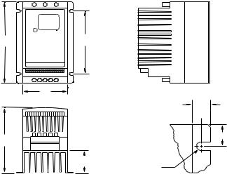
2TCF DIMENSIONS
H  R
R
W
T

 U
U 
D V
PS
Dia. Slot
Mounting Tab Detail
If R < 6..30" (160) S = 0..19" (5)
T = 0..38" (10)
U = 0..18" (5)
V = 0..66" (17)
If R = 6..30" (160) S = 0..28" (7)
T = 0..50" (13)
U = 0..24" (6)
V = 0..90" (23)
3

HP |
kW |
INPUT |
MODEL |
H |
W |
D |
P |
R |
|
VOLTAGE |
|||||||||
0..5 |
0..37 |
208 / 240 |
TF205Y |
5..75 (146) |
2..88 (73) |
3..94 (100) |
0..80 (20) |
4..37 (111) |
|
|
|
|
|
|
|
|
|||
400 / 480 |
TF405 |
5..75 (146) |
3..76 (96) |
5..24 (133) |
1..90 (48) |
4..37 (111) |
|||
|
|
||||||||
|
|
|
|
|
|
|
|
|
|
|
|
208 / 240 |
TF210Y |
5..75 (146) |
2..88 (73) |
4..74 (120) |
1..60 (41) |
4..37 (111) |
|
|
|
|
|
|
|
|
|
|
|
1 |
0..75 |
208 / 240 |
TF210 |
5..75 (146) |
2..88 (73) |
4..74 (120) |
1..60 (41) |
4..37 (111) |
|
|
|
|
|
|
|
|
|||
400 / 480 |
TF410 |
5..75 (146) |
3..76 (96) |
5..24 (133) |
1..90 (48) |
4..37 (111) |
|||
|
|
||||||||
|
|
|
|
|
|
|
|
|
|
|
|
480 / 590 |
TF510 |
5..75 (146) |
3..76 (96) |
5..24 (133) |
1..90 (48) |
4..37 (111) |
|
|
|
|
|
|
|
|
|
|
|
|
|
208 / 240 |
TF215Y |
5..75 (146) |
3..76 (96) |
5..24 (133) |
1..90 (48) |
4..37 (111) |
|
|
|
|
|
|
|
|
|
|
|
1..5 |
1..1 |
208 / 240 |
TF215 |
5..75 (146) |
2..88 (73) |
5..74 (146) |
2..60 (66) |
4..37 (111) |
|
|
|
|
|
|
|
|
|
|
|
|
|
400 / 480 |
TF415 |
5..75 (146) |
3..76 (96) |
5..24 (133) |
1..90 (48) |
4..37 (111) |
|
|
|
|
|
|
|
|
|
|
|
|
|
208 / 240 |
TF220Y |
5..75 (146) |
3..76 (96) |
6..74 (171) |
3..40 (86) |
4..37 (111) |
|
|
|
|
|
|
|
|
|
|
|
2 |
1..5 |
208 / 240 |
TF220 |
5..75 (146) |
3..76 (96) |
6..74 (171) |
3..40 (86) |
4..37 (111) |
|
|
|
|
|
|
|
|
|||
400 / 480 |
TF420 |
5..75 (146) |
3..76 (96) |
6..74 (171) |
3..40 (86) |
4..37 (111) |
|||
|
|
||||||||
|
|
|
|
|
|
|
|
|
|
|
|
480 / 590 |
TF520 |
5..75 (146) |
3..76 (96) |
6..74 (171) |
3..40 (86) |
4..37 (111) |
|
|
|
|
|
|
|
|
|
|
|
|
|
208 / 240 |
TF230Y |
5..75 (146) |
3..76 (96) |
6..74 (171) |
3..40 (86) |
3..25 (83) |
|
|
|
|
|
|
|
|
|
|
|
3 |
2..2 |
208 / 240 |
TF230 |
5..75 (146) |
3..76 (96) |
6..74 (171) |
3..40 (86) |
3..25 (83) |
|
|
|
|
|
|
|
|
|||
400 / 480 |
TF430 |
5..75 (146) |
3..76 (96) |
6..74 (171) |
3..40 (86) |
3..25 (83) |
|||
|
|
||||||||
|
|
|
|
|
|
|
|
|
|
|
|
480 / 590 |
TF530 |
5..75 (146) |
3..76 (96) |
6..74 (171) |
3..40 (86) |
3..25 (83) |
|
|
|
|
|
|
|
|
|
|
|
|
|
208 / 240 |
TF250 |
5..75 (146) |
3..76 (96) |
6..74 (171) |
3..40 (86) |
3..25 (83) |
|
|
|
|
|
|
|
|
|
|
|
5 |
4..0 |
400 / 480 |
TF450 |
5..75 (146) |
3..76 (96) |
6..74 (171) |
3..40 (86) |
3..25 (83) |
|
|
|
|
|
|
|
|
|
|
|
|
|
480 / 590 |
TF550 |
5..75 (146) |
3..76 (96) |
6..74 (171) |
3..40 (86) |
3..25 (83) |
|
|
|
|
|
|
|
|
|
|
|
|
|
208 / 240 |
TF275 |
7..75 (197) |
5..02 (128) |
7..18 (182) |
3..40 (86) |
4..81 (122) |
|
|
|
|
|
|
|
|
|
|
|
7..5 |
5..5 |
400 / 480 |
TF475 |
7..75 (197) |
5..02 (128) |
7..18 (182) |
3..40 (86) |
4..81 (122) |
|
|
|
|
|
|
|
|
|
|
|
|
|
480 / 590 |
TF575 |
7..75 (197) |
5..02 (128) |
7..18 (182) |
3..40 (86) |
4..81 (122) |
|
|
|
|
|
|
|
|
|
|
|
|
|
208 / 240 |
TF2100 |
7..75 (197) |
5..02 (128) |
7..18 (182) |
3..40 (86) |
4..81 (122) |
|
|
|
|
|
|
|
|
|
|
|
10 |
7..5 |
400 / 480 |
TF4100 |
7..75 (197) |
5..02 (128) |
7..18 (182) |
3..40 (86) |
4..81 (122) |
|
|
|
|
|
|
|
|
|
|
|
|
|
480 / 590 |
TF5100 |
7..75 (197) |
5..02 (128) |
7..18 (182) |
3..40 (86) |
4..81 (122) |
|
|
|
|
|
|
|
|
|
|
4

3TCF MODEL DESIGNATION CODE
The TCF model number gives a full description of the basic drive unit..
EXAMPLE: TF210Y = TCF Series, 208/240 Vac, 1 HP, single or three phase input
TF 2 10 Y
Series:
TF = TCF Series Sensor less Vector Variable Speed AC Motor Drive
Input Voltage:
2 = 208/240 Vac (For 208, 230, and 240 Vac; 50 or 60 Hz)
4= 400/480 Vac (For 380, 415, 440, 460 and 480 Vac; 50 or 60 Hz)
5= 480/590 Vac (For 440, 460, 480, 575 and 600 Vac; 50 or 60 Hz)
Rating: |
|
|
|
|
05 |
= ½ HP (0..37 kW) |
30 |
= |
3 HP (2..2 kW) |
10 |
= 1 HP (0..75 kW) |
50 |
= |
5 HP (4..0 kW) |
15 |
= 1½ HP (1..1 kW) |
75 |
= |
7½ HP (5..5 kW) |
20 |
= 2 HP (1..5 kW) |
100 |
= |
10 HP (7..5 kW) |
|
|
|
|
|
Input Phase: |
|
|
|
|
Y |
= Single or three phase input.. |
|
|
|
No character indicates three phase input only |
|
|||
5

4TCF SPECIFICATIONS
Specification |
Range |
|
|
Storage Temperature |
-20° to 70° C |
|
|
Ambient Operating Temperature |
0° to 50° C (derate 2..5% per °C above 50°) |
|
|
Ambient Humidity |
< 95% (non-condensing) |
|
|
Maximum Altitude |
3300 ft. (1000 m) above sea level (derate 5% per additional 3300 ft..) |
|
|
Input Line Voltages |
208/240 Vac, 400/480 Vac, 480/590 Vac |
|
|
Input Voltage Tolerance |
+10%, -15% |
|
|
Input Frequency Tolerance |
48 to 62 Hz |
|
|
Output Wave Form |
Sine Coded PWM |
|
|
Output Frequency |
0 - 240 Hz (consult factory for higher output frequencies) |
|
|
Carrier Frequency |
2 kHz, 4 kHz, 8 kHz (8 kHz requires derating; see parameter P02) |
|
|
Service Factor |
1..00 (up to 4 kHz carrier; derate for 8 kHz; see parameter P02) |
|
|
Efficiency |
Up to 98% |
|
|
Power Factor (displacement) |
0..96 or better |
|
|
Overload Current Capacity |
150% for 60 seconds, 200% for 25 seconds |
|
|
Speed Reference Follower |
0-10 VDC, 4-20 mA |
|
|
Control Voltage |
15 VDC |
|
|
Power Supply for Auxiliary Relays |
50 mA at 12 VDC |
|
|
Analog Output |
0 - 10 VDC or 2 - 10 VDC: Proportional to speed, load, or torque |
|
|
Digital Outputs |
Open-collector outputs: 50 mA at 30 VDC |
|
|
Earth Leakage Current |
< 3..5 mA to earth ground |
|
|
6
5TCF RATINGS
MODEL |
FOR MOTORS |
|
INPUT (50-60 Hz) |
OUTPUT |
HEAT LOSS |
|||||
|
|
|
|
|
|
|||||
NUMBER |
RATED |
INPUT |
CURRENT |
POWER |
CURRENT |
(WATTS) |
||||
(NOTE 1) |
|
|
(NOTE 5) |
|||||||
HP |
kW |
PHASE |
(AMPS) |
(kVA) |
(AMPS) |
|||||
|
|
|||||||||
|
|
|
|
|
|
|
|
|||
|
|
|
|
|
|
|
|
|||
TF200Y SERIES (NOTE 2) |
|
208 / 240 Vac |
|
0 - 200 / 230 Vac |
|
|||||
|
|
|
|
|
|
|
|
|
||
TF205Y |
0..5 |
0..37 |
1 |
5..4 |
/ 4..7 |
1..2 |
2..5 / 2..2 |
26 |
||
TF205Y |
0..5 |
0..37 |
3 |
3..1 |
/ 2..7 |
1..1 |
2..5 / 2..2 |
26 |
||
TF210Y |
1 |
0..75 |
1 |
10..6 / 9..2 |
2..2 |
4..8 / 4..2 |
49 |
|||
TF210Y |
1 |
0..75 |
3 |
5..8 |
/ 5..1 |
2..1 |
4..8 / 4..2 |
49 |
||
TF215Y |
1..5 |
1..1 |
1 |
13..9 |
/ 12..0 |
2..9 |
6..9 / 6..0 |
82 |
||
TF215Y |
1..5 |
1..1 |
3 |
8..0 |
/ 6..9 |
2..9 |
6..9 / 6..0 |
82 |
||
TF220Y |
2 |
1..5 |
1 |
14..8 |
/ 12..9 |
3..1 |
7..8 / 6..8 |
86 |
||
TF220Y |
2 |
1..5 |
3 |
9..1 |
/ 7..9 |
3..2 |
7..8 / 6..8 |
86 |
||
TF230Y |
3 |
2..2 |
1 |
19..7 |
/ 17..1 |
4..1 |
11..0 / 9..6 |
130 |
||
TF230Y |
3 |
2..2 |
3 |
12..4 |
/ 10..8 |
4..4 |
11..0 / 9..6 |
130 |
||
|
|
|
|
|
|
|
|
|||
TF200 SERIES (NOTE 2) |
|
208 / 240 Vac |
|
0 - 200 / 230 Vac |
|
|||||
|
|
|
|
|
|
|
|
|
|
|
TF210 |
1 |
0..75 |
3 |
5..8 |
/ 5..1 |
2..1 |
4..8 |
/ 4..2 |
41 |
|
TF215 |
1..5 |
1..1 |
3 |
8..0 |
/ 6..9 |
2..9 |
6..9 |
/ 6..0 |
69 |
|
TF220 |
2 |
1..5 |
3 |
9..1 |
/ 7..9 |
3..3 |
7..8 |
/ 6..8 |
78 |
|
TF230 |
3 |
2..2 |
3 |
12..4 |
/ 10..8 |
4..5 |
11..0 / 9..6 |
117 |
||
TF250 |
5 |
4..0 |
3 |
19..6 |
/ 17..1 |
7..1 |
17..5 |
/ 15..2 |
187 |
|
TF275 |
7..5 |
5..5 |
3 |
28 |
/ 25 |
10..3 |
25 |
/ 22 |
286 |
|
TF2100 |
10 |
7..5 |
3 |
34 |
/ 32 |
13..1 |
30 |
/ 28 |
379 |
|
|
|
|
|
|
|
|
|
|
|
|
NOTE 1: Refer to Section 3 for model number breakdown..
NOTE 2: The higher current ratings are for 208 Vac input and the lower current ratings are for 240 Vac input.. NOTE 5: Values are worst-case (not typical) for 4kHz carrier frequency at full speed and full load..
7

MODEL |
FOR MOTORS |
|
INPUT (50-60 Hz) |
|
OUTPUT |
HEAT LOSS |
|||||
|
|
|
|
|
|
|
|
||||
NUMBER |
RATED |
INPUT |
CURRENT |
|
POWER |
CURRENT |
(WATTS) |
||||
(NOTE 1) |
|
|
|
(NOTE 5) |
|||||||
|
|
PHASE |
(AMPS) |
|
(kVA) |
(AMPS) |
|||||
|
HP |
kW |
|
|
|||||||
|
|
|
|
|
|
|
|
|
|
||
TF400 SERIES (NOTE 3) |
|
400 / 480 Vac |
|
|
0 - 400 / 460 Vac |
|
|||||
|
|
|
|
|
|
|
|
|
|
|
|
TF405 |
0..5 |
0..37 |
3 |
1..6 |
/ 1..4 |
|
1..1 |
1..3 |
/ 1..1 |
26 |
|
TF410 |
1 |
0..75 |
3 |
2..9 |
/ 2..5 |
|
2..1 |
2..4 |
/ 2..1 |
40 |
|
TF415 |
1..5 |
1..1 |
3 |
4..0 |
/ 3..6 |
|
3..0 |
3..4 |
/ 3..0 |
56 |
|
TF420 |
2 |
1..5 |
3 |
4..6 |
/ 4..0 |
|
3..3 |
3..9 |
/ 3..4 |
67 |
|
TF430 |
3 |
2..2 |
3 |
6..2 |
/ 5..4 |
|
4..5 |
5..5 |
/ 4..8 |
100 |
|
TF450 |
5 |
4..0 |
3 |
10..6 / 8..8 |
|
7..1 |
9..4 |
/ 7..8 |
168 |
||
TF475 |
7..5 |
5..5 |
3 |
14..2 |
/ 12..4 |
|
10..3 |
12..6 |
/ 11..0 |
254 |
|
TF4100 |
10 |
7..5 |
3 |
18..1 |
/ 15..8 |
|
13..1 |
16..1 |
/ 14..0 |
310 |
|
|
|
|
|
|
|
|
|
|
|
||
TF500 SERIES (NOTE 4) |
|
480 / 590 Vac |
|
|
0 - 460 / 575 Vac |
|
|||||
|
|
|
|
|
|
|
|
|
|
|
|
TF510 |
1 |
0..75 |
3 |
2..2 |
/ 2..0 |
|
1..9 |
/ 2..0 |
1..9 |
/ 1..7 |
40 |
TF520 |
2 |
1..5 |
3 |
4..0 |
/ 3..5 |
|
3..3 |
/ 3..6 |
3..4 |
/ 3..0 |
67 |
TF530 |
3 |
2..2 |
3 |
4..7 |
/ 4..7 |
|
3..9 |
/ 4..8 |
4..2 |
/ 4..2 |
100 |
TF550 |
5 |
3..7 |
3 |
7..4 |
/ 7..4 |
|
6..1 |
/ 7..5 |
6..6 |
/ 6..6 |
168 |
TF575 |
7..5 |
5..5 |
3 |
11..2 |
/ 11..2 |
|
9..3 / 11..4 |
9..9 |
/ 9..9 |
254 |
|
TF5100 |
10 |
7..5 |
3 |
13..7 |
/ 13..7 |
|
11..4 |
/ 14..0 |
12..2 |
/ 12..2 |
310 |
|
|
|
|
|
|
|
|
|
|
|
|
NOTE 1: Refer to Section 3 for model number breakdown..
NOTE 3: The higher current ratings are for 400 Vac input and the lower current ratings are for 480 Vac input.. NOTE 4: The higher current ratings are for 480 Vac input and the lower current ratings are for 590 Vac input.. NOTE 5: Values are worst-case (not typical) for 4kHz carrier frequency at full speed and full load
8
6INSTALLATION
NOTE
TCF Series drives are intended for inclusion within other equipment, by professional electrical installers according to EN 61000-3-2. The TCF drive is not intended for stand-alone operation
WARNING!
Drives must NOT be installed where subjected to adverse environmental conditions such as: combustible, oily, or hazardous vapors or dust; excessive moisture or dirt; vibration; excessive ambient temperatures. Consult LenzeAC Tech for more information on the suitability of a drive to a particular environment.
TCF models are suitable for UL pollution degree 2 environment only, and MUST be installed in an electrical enclosure which will provide complete mechanical protection and will maintain the internal temperature within the drive’s ambient operating temperature rating. All drive models MUST be mounted in a vertical position for proper heatsink cooling..
Maintain a minimum spacing around the drive of at least 1 inch (25 mm) on each side and 2 inches (50 mm) on the top and bottom for units rated up to 5 HP (3..7 kW). For units rated 7..5 - 10 HP (5..5 - 7..5 kW), maintain at least 2 inches (50 mm) on each side and 4 inches (100 mm) on the top and bottom. Allow more spacing if the drive is mounted next to other heatproducing equipment. Do not mount drives above other drives or heat producing equipment. Fans or blowers should be used to insure proper cooling in tight quarters..
In order to properly size an enclosure, the heat generated by the drive(s) must be known. Refer to the HEAT LOSS column in Section 5 - TCF RATINGS. An enclosure manufacturer can then determine the required enclosure size based on the total heat generated inside the enclosure (from the drive(s) and other heat sources), the maximum allowable temperature inside the enclosure, the maximum ambient temperature outside the enclosure, and the enclosure properties..
The TCF Series is UL approved for solid state motor overload protection. Therefore, a separate thermal overload relay is not required for single motor applications..
9

6..1 INSTALLATION AFTER A LONG PERIOD OF STORAGE
STOP!
Severe damage to the drive can result if it is operated after a long period of storage or inactivity without reforming the DC bus capacitors!
If input power has not been applied to the drive for a period of time exceeding three years (due to storage, etc), the electrolytic DC bus capacitors within the drive can change internally, resulting in excessive leakage current. This can result in premature failure of the capacitors if the drive is operated after such a long period of inactivity or storage..
In order to reform the capacitors and prepare the drive for operation after a long period of inactivity, apply input power to the drive for 8 hours prior to actually operating the motor..
6..2 EXPLOSION PROOF APPLICATIONS
Explosion proof motors that are not rated for inverter use lose their certification when used for variable speed. Due to the many areas of liability that may be encountered when dealing with these applications, the following statement of policy applies:
“Lenze AC Tech inverter products are sold with no warranty of fitness for a particular purpose or warranty of suitability for use with explosion proof motors. Lenze AC Tech accepts no responsibility for any direct, incidental or consequential loss, cost, or damage that may arise through the use of its AC inverter products in these applications. The purchaser expressly agrees to assume all risk of any loss, cost, or damage that may arise from such application."
10

7INPUT AC POWER REQUIREMENTS
DANGER!
Hazard of electrical shock! Capacitors retain charge after they've been removed. Disconnect incoming power and wait until the voltage between terminals B+ and B- is 0 VDC before servicing the drive..
The input voltage must match the nameplate voltage rating of the drive. Voltage fluctuation must not vary by greater than 10% over voltage or 15% under voltage..
NOTE
Drives with dual input voltage ratings must be programmed for the proper supply voltage (refer to Parameter 01 - LINE VOLTAGE SELECTION in
Section 15 - DESCRIPTION OF PARAMETERS)..
The drive is suitable for use on a circuit capable of delivering not more than 5,000 RMS symmetrical amperes at 5 HP (4..0 kW) and below, and 18,000 RMS symmetrical amperes at 7..5 - 10 HP (5..5 - 7..5 kW), at the drive’s rated voltage..
If the kVA rating of the AC supply transformer is greater than 10 times the input kVA rating of the drive(s), an isolation transformer or 2-3% input line reactor must be added to the line side of the drive(s)..
Three phase voltage imbalance must be less than 2..0% phase to phase. Excessive phase to phase imbalance can cause severe damage to the drive’s power components..
Motor voltage should match line voltage in normal applications. The drive’s maximum output voltage will equal the input voltage. Use extreme caution when using a motor with a voltage rating which is different from the input line voltage..
7..1 INPUT VOLTAGE RATINGS
TF200 Series drives are rated for 208/240 Vac, three phase, 50-60 Hz input. The drive will function with input voltages of 208 to 240 Vac (+10%, -15%) at 48 to 62 Hz..
TF200Y Series drives are rated for 208/240 Vac, single or three phase, 50-60 Hz input. The drive will function with input voltage of 208 to 240 Vac (+10%, -15%) at 48 to 62 Hz..
TF400 Series drives are rated for 400/480 Vac three phase, 50-60 Hz input. The drive will function with input voltages of 400 to 480 Vac (+10%, -15%) at 48 to 62 Hz..
TF500 Series drives are rated for 480/590 Vac, three phase, 50-60 Hz input, and will function with input voltages of 480 to 590 Vac (+10%, -15%) at 48 to 62 Hz..
NOTE
Parameter 01 - LINE VOLTAGE SELECTION must be programmed according to the applied input voltage. Refer to Section 15 - DESCRIPTION OF PARAMETERS..
11
7..2 INPUT FUSING & DISCONNECT REQUIREMENTS
A circuit breaker or a disconnect switch with fuses must be provided in accordance with the National Electric Code (NEC) and all local codes. Refer to the following tables for proper fuse/circuit breaker ratings and wire sizes..
INPUT FUSE & CIRCUIT BREAKER RATINGS
208/240 Vac, 1 phase |
208/240 Vac, 3 phase |
400/480 Vac, 3 phase |
480/590 Vac, 3 phase |
|||||
|
|
|
|
|
|
|
|
|
MODEL |
RATING |
MODEL |
RATING |
MODEL |
RATING |
MODEL |
RATING |
|
|
|
|
|
|
|
|
|
|
TF205Y |
10 A |
TF205Y |
10 A |
TF405 |
10 A |
|
|
|
TF210Y |
15 A |
TF210(Y) |
10 A |
TF410 |
10 A |
TF510 |
10 A |
|
TF215Y |
20 A |
TF215(Y) |
12 / 10 A |
TF415 |
10 A |
|
|
|
|
|
|||||||
TF220Y |
25 / 20 A |
TF220(Y) |
15 / 12 A |
TF420 |
10 A |
TF520 |
10 A |
|
TF230Y |
30 / 25 A |
TF230(Y) |
20 / 15 A |
TF430 |
10 A |
TF530 |
10 A |
|
|
|
TF250 |
30 / 25 A |
TF450 |
15 A |
TF550 |
12 A |
|
|
|
|||||||
|
|
TF275 |
45 / 40 A |
TF475 |
20 A |
TF575 |
20 A |
|
|
|
|||||||
|
|
TF2100 |
50 / 50 A |
TF4100 |
30 / 25 A |
TF5100 |
20 A |
|
|
|
|||||||
|
|
|
|
|
|
|
|
|
NOTE
• Applicable national and local electrical codes take precedence over recommendations in these tables..
•Use UL Class CC fast-acting, current limiting type fuses. Select fuses with low I2T values, rated at 200,000 AIC. Recommended fuses are Bussman KTK-R, JJN, and JJS. Similar fuses with equivalent ratings by other manufacturers may also be acceptable..
WARNING!
This product can cause a DC current in the protective conductor. Where a residual current device (RCD) is used for protection in case of direct or indirect contact, only an RCD of Type B is allowed on the supply side of this product. Otherwise, another protective measure shall be applied, such as separation from the environment by double or reinforced insulation, or isolation from the supply system by a transformer..
Observe the following when using RCDs:
1..Only install the RCD between the supply mains and drive controller..
2..The RCD can be activated by:
•capacitive leakage currents between the cable screens during operation (especially with long, screened motor cables)
•connecting several drives to the mains at the same time
•additional RFI filters
12
7..3 |
INPUT WIRE SIZE REQUIREMENTS |
|
|
|
|
|
||||||
|
|
|
|
|
|
|
|
|||||
|
|
|
INPUT WIRE SIZE REQUIREMENTS |
|
|
|
||||||
208/240 Vac, 1 phase |
208/240 Vac, 3 phase |
400/480 Vac, 3 phase |
480/590 Vac, 3 phase |
|||||||||
|
|
|
|
|
|
|
|
|
|
|
|
|
MODEL |
AWG |
mm2 |
MODEL |
AWG |
mm2 |
MODEL |
AWG |
mm2 |
MODEL |
AWG |
mm2 |
|
|
|
|
|
|
|
|
|
|
|
|
|
|
TF205Y |
14 |
1..5 |
TF205Y |
14 |
1..5 |
TF405 |
14 |
1..5 |
|
|
|
|
TF210Y |
14 |
1..5 |
TF210(Y) |
14 |
1..5 |
TF410 |
14 |
1..5 |
TF510 |
14 |
1..5 |
|
TF215Y |
12 |
2..5 |
TF215(Y) |
14 |
1..5 |
TF415 |
14 |
1..5 |
|
|
|
|
|
|
|
||||||||||
TF220Y |
12 |
2..5 |
TF220(Y) |
14 |
1..5 |
TF420 |
14 |
1..5 |
TF520 |
14 |
1..5 |
|
TF230Y |
10 |
4..0 |
TF230(Y) |
12 |
2..5 |
TF430 |
14 |
1..5 |
TF530 |
14 |
1..5 |
|
|
|
|
TF250 |
10 |
4..0 |
TF450 |
14 |
1..5 |
TF550 |
14 |
1..5 |
|
|
|
|
||||||||||
|
|
|
TF275 |
8 |
6..0 |
TF475 |
12 |
2..5 |
TF575 |
14 |
1..5 |
|
|
|
|
||||||||||
|
|
|
TF2100 |
8 |
10 |
TF4100 |
10 |
4..0 |
TF5100 |
12 |
2..5 |
|
|
|
|
||||||||||
7..4 INSTALLATION ACCORDING TO EMC REQUIREMENTS
This drive can be installed to meet the European standards for Electromagnetic Compatibility
(EMC) requirements. These requirements govern the permissible electromagnetic emissions and immunity, both radiated and conducted, of a drive system..
The EMC requirements apply to the final installation in its entirety, not to the individual components used. Because every installation is different, the recommended installation should follow these guidelines as a minimum. Additional equipment (such as ferrite core absorbers on power conductors) or alternative wiring practices may be required to meet conformance in some installations..
Filter: The input to the drive (or group of drives) must include a filter to reduce the electrical noise reflected back to the AC Line. To meet the industrial standards set by the EU, EN 61800- 3 for conducted emissions and EN 55011 for radiated emissions to class A compliance, the drive must be installed with an appropriate filter and a maximum motor cable length of 10m..
EMC |
|
|
|
|
|
|
|
|
|
|
Compliance with EN 61800-3/A11 |
|
|
|
|
|
|
|
|
|
|
|
|
|
|
|
|
|
|
|
|
|
Installation: Shielded cable must be used for all control and power |
|
|
|
|
|
|
|
|
|
|
cables and exposed wiring must be kept as short as possible.. |
|
|
|
|
|
|
|
|
|
|
|
B |
|
|
|
|
|
|
|
|
|
|
|
|
|
|
|
|
|
|
|
|
A Screen clamps |
|
|
|
|
|
|
|
|
|
|
|
|
|
|
|
|
|
|
|
||
|
|
|
|
|
|
|
E |
|||
B Control cable |
|
|
|
|
|
|
|
|
|
|
|
|
|
|
|
C |
|
|
|
|
|
C Low-capacitance motor cable |
|
|
|
|
|
|
|
|
|
|
|
|
|
|
|
|
|
|
|
|
|
|
|
|
|
|
|
|
D |
|
||
(core/core < 75 pF/m, core/screen < 150 pF/m) |
|
|
|
A |
|
|
|
|
||
|
|
|
|
|
|
|
|
|
||
|
|
|
|
|
|
|
|
|
|
|
|
|
|
|
|
|
|
|
|
|
|
D Electrically conductive mounting plate |
|
|
|
|
|
|
|
|
|
|
E Filter |
|
|
|
|
|
|
|
SM01 1 |
||
|
|
|
|
|
|
|
|
|
|
|
13
8POWER WIRING
DANGER!
Hazard of electrical shock!
Capacitors retain charge after power is removed. Disconnect incoming power and wait until the voltage between terminals B+ and B- is 0 VDC before servicing the drive..
Note drive input and output current ratings and check applicable electrical codes for required wire type and size, grounding requirements, over-current protection, and incoming power disconnect, before wiring the drive. Size conservatively to minimize voltage drop..
Refer to Section 9 - TCF POWER WIRING DIAGRAM for information on torque and wire stripping requirements for power wiring..
Input fusing and a power disconnect switch or contactor MUST be wired in series with terminals L1, L2, and L3 for three phase input models. For 208/240 Vac single phase input models, use terminals L1 and L3. This disconnect must be used to power down the drive when servicing, or when the drive is not to be operated for a long period of time, but should not be used to start and stop the motor..
Repetitive cycling of a disconnect or input contactor (more than once every two minutes) may cause damage to the drive.
8..1 WIRING FOR SINGLE PHASE OR THREE PHASE INPUT
If the drive is rated for single and three phase input (TF200Y models), wire to terminals L1 and L3 for single phase input, or wire to terminals L1, L2, and L3 for three phase input..
If the drive is rated for three phase input, wire the input to terminals L1, L2, and L3..
All three power output wires, from terminals T1, T2, and T3 to the motor, must be kept tightly bundled and run in a separate conduit away from all other power and control wiring. It is not recommended to install contactors or disconnect switches between the drive and motor. Operating such devices while the drive is running can potentially cause damage to the drive's power components. If such a device is required, it should only be operated when the drive is in a STOP state. If there is potential for the device to be opened while the drive is running, the drive must be programmed for COAST to stop (refer to Parameter 04 - STOP METHOD), and an auxiliary contact on the device must be interlocked with the drive's run circuit. This will give the drive a stop command at the same time the device opens, and will not allow the drive to start again until the device is closed..
14

9TCF POWER WIRING DIAGRAM
THREE PHASE INPUT |
SINGLE PHASE INPUT |
TF230Y & |
|
(ALL SERIES) |
(TF200Y SERIES) |
||
TF250 only |
|||
|
|
7..0 lb-in / 0..8 Nm |
|
|
|
0..24 in / 6 mm |
L1 |
L2 |
L3 |
L1 |
L2 |
L3 |
For all other models, use output torque values..
|
|
OUTPUT (ALL SERIES) |
0..5 - 5 HP |
7..5 - 10 HP |
|
(0..37 - 3..7 kW) |
(5..5 - 7..5 kW) |
T1 T2 T3 B- B+ |
4..5 lb-in / 0..5 Nm |
10 lb-in / 1..2 Nm |
|
0..24 in / 6 mm |
0..35 in / 9 mm |
|
|
+ |
3 PHASE |
DC BUS |
AC MOTOR |
VOLTAGE |
STOP!
•Do NOT connect AC line power to output terminals T1, T2, or T3. Severe damage to the drive will result..
•Leakage current may exceed 3..5 mA AC. Minimum size of the protective earth conductor shall comply with local safety regulations for high leakage current equipment..
•Wire and Ground in accordance with NEC or CEC, and all applicable local codes..
•Motor wires MUST be run in a separate steel conduit away from control wiring and incoming AC power wiring..
•Do not install contactors between the drive and the motor without consulting Lenze-AC Tech for more information. Failure to do so may result in drive damage..
•Use only UL and CSA listed and approved wire..
•Minimum wire voltage rating is 300 V for 120, 208, and 240 Vac systems, and 600 V for 400 and 480 Vac systems..
•Wire gauge must be based on a minimum of 125% of the rated input/ output current of the drive, and a minimum 75°C insulation rating. Use copper wire only..
15

10 CONTROL WIRING
10..1 CONTROL WIRING VS. POWER WIRING
External control wiring MUST be run in a separate conduit away from all other input and output power wiring. If control wiring is not kept separate from power wiring, electrical noise may be generated on the control wiring that will cause erratic drive behavior. Use twisted wires or shielded cable grounded at the drive chassis ONLY. Recommended control wire is Belden 8760 or 8770, or equivalent..
NOTE
Control terminals provide basic isolation (insulation per EN 61800-5-1). Protection against contact can only be assured by additional measures e..g. supplemental insulation..
Strip off 0..20 to 0..25 inches (5 to 6 mm) of insulation for control wiring, and torque the terminals to 2 lb-in (0..2 Nm). Be careful not to overtorque the terminals, as this will cause damage to the terminal strip. This is not covered under warranty and can only be repaired by replacing the control board..
10..2 TB-2 AND TB-4
The TB-2 terminals are the circuit common for the analog input and analog output functions. The TB-4 terminals are the reference for all of the digital inputs (TB-1, 13A, 13B, 13C, and
13D). The digital inputs are active-high as standard, but can be configured for active-low during initial set-up. Refer to APPENDIX B - INPUT ASSERTION LEVEL. When set for active-high, TB-4 is at +12 VDC..
NOTE
TB-2 may be connected to chassis ground if noise is a concern. TB-2 must be connected to chassis ground when using serial communications..
10..3 SURGE SUPPRESSION ON RELAYS
Current and voltage surges and spikes in the coils of contactors, relays, solenoids, etc, near or connected to the drive, can cause erratic drive operation. Therefore, a snubber circuit should be used on coils associated with the drive. For AC coils, snubbers should consist of a resistor and a capacitor in series across the coil. For DC coils, a free-wheeling or flyback diode should be placed across the coil. Snubbers are typically available from the manufacturer of the device..
10..4 START/STOP CONTROL
There are various control schemes that allow for 2-wire and 3-wire Start/Stop circuits. Refer to the wiring diagrams in Section 11 - TCF CONTROL WIRING DIAGRAMS
16
10..5 |
SPEED/TORQUE REFERENCE SIGNALS |
|
|
SPEED POT |
Connect the wiper of the speed pot to terminal TB-5, and the |
|
|
high and low leads to terminals TB-6 and TB-2, respectively. |
|
|
The speed pot can be 2..5kΩ up to 10kΩ.. |
|
0-10 VDC |
Wire the positive to terminal TB-5 and the negative to |
|
|
terminal TB-2. TB-5 input impedance is 120 kΩ.. |
|
-10 to +10 VDC |
Connect the signal wire to TB-5 and the common to TB-2. |
|
|
TB-5 input impedance is 120 kΩ. This signal can be used for |
|
|
speed reference only.. |
|
4-20 mA |
Wire the positive to terminal TB-25 and the negative to |
|
|
terminal TB-2. TB-25 input impedance is 100Ω.. |
10..6 SPEED REFERENCE SELECTION
If an analog speed/torque reference input is used to control the drive, terminal TB-13A, 13B,
13C, or 13D (Parameter 10, 11, 12, or 49) may be programmed as the input select for the desired analog input signal. When that TB-13 terminal is then closed to TB-4, the drive will respond to the selected analog reference input..
If an analog speed/torque reference input is not selected on the terminal strip using TB-13A, 13B, 13C, or 13D, control will default to STANDARD mode, which is governed by the setting of Parameter 05 - STANDARD REFERENCE SOURCE. The STANDARD REFERENCE SOURCE can be the s and t buttons on the front of the drive, PRESET SPEED #1 (speed mode only; not torque mode), a 0-10 VDC signal, or a 4-20 mA signal..
0-10 VDC, -10 to +10 VDC, and 4-20 mA INPUT SIGNALS
TB-13A, TB-13B, TB-13C, and TB-13D can all be programmed to select a 0-10 VDC or 4-20 mA analog speed/torque reference input. To select a -10 to +10 VDC bipolar speed input, Parameter 07 - BIPOLAR REFERENCE SELECTION must be set to ENABLE (02), which disables all other speed references except for JOG FORWARD and JOG REVERSE (refer to Parameter 07)..
PRESET SPEEDS
TB-13A (or 13D) can be programmed to select PRESET SPEED #1, TB-13B to select PRESET SPEED #2, and TB-13C to select PRESET SPEED #3. There are a total
of seven preset speeds, which are activated by different combinations of contact closures between TB-13A (or 13D), 13B, 13C and TB-4. Refer to Parameters 31-37 in
Section 15 - DESCRIPTION OF PARAMETERS..
JOG (not available in Vector Torque mode)
TB-13B can be programmed for JOG FORWARD, and TB-13C can be programmed for JOG REVERSE. The JOG FORWARD speed is set by PRESET SPEED #2, and the JOG REVERSE speed is set by PRESET SPEED #4. Close TB-13B or TB-13C to TB-4 to JOG in the desired direction, and open the contact to STOP..
17

WARNING!
When operating in JOG mode, the STOP signal and the AUXILIARY STOP function (Parameters 10-12) WILL NOT stop the drive. To stop the drive, remove the JOG command..
JOG REVERSE will operate the drive in reverse rotation even if ROTATION
DIRECTION (Parameter 17) is set to FORWARD ONLY
NOTE
If the drive is commanded to JOG while running, the drive will enter JOG mode, but when the JOG command is removed, the drive will STOP..
MOTOR OPERATED POT (MOP) / FLOATING POINT CONTROL
TB-13B and TB-13C are used for this function, which controls the drive speed using contacts wired to the terminal strip. Program TB-13B for DECREASE FREQ (05), and program TB13C for INCREASE FREQ (05)..
Closing TB-13B to TB-4 will cause the speed setpoint to decrease until the contact is opened.
Closing TB-13C to TB-4 will cause the speed setpoint to increase until the contact is opened. The INCREASE FREQ function will only operate while the drive is running..
NOTE
If TB-13A, TB-13B, TB-13C, and TB-13D are all programmed to select speed references, and two or more of the terminals are closed to TB-4, the higher terminal has priority and will override the others. For example, if TB-13A is programmed to select 0-10 VDC, and TB-13C is programmed to select PRESET SPEED #3, closing both terminals to TB-4 will cause the drive to respond to PRESET SPEED #3 because TB-13C overrides TB-13A..
The exception to this is the MOP function, which requires the use of TB-13B and TB-13C. This leaves TB-13A and TB-13D to be used for other functions. If TB-13A or TB-13D is programmed for a speed reference and that terminal is closed to TB-4, it will override the
MOP function..
NOTE
This analog output signal cannot be used with "loop-powered" devices that derive power from a 4-20 mA signal..
18
10..7 ANALOG OUTPUT SIGNALS
Terminal TB-30 can provide a 0-10 VDC or a 2-10 VDC signal proportional to output frequency, load, or torque. The 2-10 VDC signal can be converted to a 4-20 mA signal using a resistor in series with the signal such that the total load resistance is 500 Ohms. Refer to TB-30 OUTPUT (Parameter 08) in Section 15 - DESCRIPTION OF PARAMETERS..
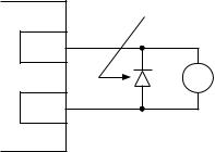
10..8 DRIVE STATUS DIGITAL OUTPUTS
There are two open-collector outputs at terminals TB-14 and TB-15. The open-collector circuits are current-sinking types rated at 30 VDC and 50 mA maximum..
The open-collector outputs can be programmed to indicate any of the following: RUN,
FAULT, INVERSE FAULT, FAULT LOCKOUT, AT SPEED, ABOVE PRESET SPEED #3, CURRENT LIMIT, AUTO SPEED MODE, and REVERSE. Refer to Parameters 06 and 13 in
Section 15 - DESCRIPTION OF PARAMETERS..
The following diagram illustrates how the 12 VDC power supply at TB-11 can be used with the opencollector output to drive an external relay..
TCF TERMINAL STRIP
DIODE SNUBBER (1N4148 or Equivalent)
TB-11
RELAY COIL
TB-14
19
 Loading...