


 Loading...
EDS94AYAE
.G)!
Ä.G)!ä
L−force Drives
Translation Manual
9400
E94AYAE − SM301
Safety module
l

,Please read these instructions and the documentation of the standard device before you start working!
Observe the safety instructions given therein!
© 2014 Lenze Automation GmbH, Hans−Lenze−Str. 1, D−31855 Aerzen
No part of this documentation may be reproduced or made accessible to third parties without written consent by Lenze Automation GmbH.
All information given in this documentation has been selected carefully and complies with the hardware and software described. Nevertheless, discrepancies cannot be ruled out. We do not take any responsibility or liability for any damage that may occur. Necessary corrections will be included in subsequent editions.
|
|
|
Safety engineering |
1 |
|
|
|
Contents |
|
|
|
|
|
|
1 |
|
Safety engineering |
|
|
Contents |
|
|
|
|
1 |
Safety engineering . . . . . . . . . . . . . . . . . . . . . . . . . . . . . . . . . . . . . . . . . . . . . . . . . . . . . . . . |
3 |
||
|
1.1 |
Basics . |
. . . . . . . . . . . . . . . . . . . . . . . . . . . . . . . . . . . . . . . . . . . . . . . . . . . . . . . . . . . . . |
5 |
|
|
1.1.1 |
Introduction . . . . . . . . . . . . . . . . . . . . . . . . . . . . . . . . . . . . . . . . . . . . . . . . . |
5 |
|
|
1.1.2 |
Drive−based safety with L−force | 9400 . . . . . . . . . . . . . . . . . . . . . . . . . . . |
5 |
|
|
1.1.3 |
Terms and abbreviations of the safety engineering . . . . . . . . . . . . . . . . |
6 |
|
|
1.1.4 |
Important notes . . . . . . . . . . . . . . . . . . . . . . . . . . . . . . . . . . . . . . . . . . . . . . |
7 |
|
|
1.1.5 |
Safety instructions . . . . . . . . . . . . . . . . . . . . . . . . . . . . . . . . . . . . . . . . . . . . |
8 |
|
|
1.1.6 |
Hazard and risk analysis . . . . . . . . . . . . . . . . . . . . . . . . . . . . . . . . . . . . . . . |
10 |
|
|
1.1.7 |
Standards . . . . . . . . . . . . . . . . . . . . . . . . . . . . . . . . . . . . . . . . . . . . . . . . . . . |
10 |
|
|
1.1.8 |
Safety instructions for the installation according to UL or UR . . . . . . . . |
10 |
|
|
1.1.9 |
Overview of sensors . . . . . . . . . . . . . . . . . . . . . . . . . . . . . . . . . . . . . . . . . . . |
11 |
|
1.2 |
Device modules . . . . . . . . . . . . . . . . . . . . . . . . . . . . . . . . . . . . . . . . . . . . . . . . . . . . . . |
12 |
|
|
|
1.2.1 |
Slot . . . . . . . . . . . . . . . . . . . . . . . . . . . . . . . . . . . . . . . . . . . . . . . . . . . . . . . . . |
12 |
|
|
1.2.2 |
Function mode of the safety modules . . . . . . . . . . . . . . . . . . . . . . . . . . . . |
14 |
|
|
1.2.3 |
SM301 safety module . . . . . . . . . . . . . . . . . . . . . . . . . . . . . . . . . . . . . . . . . |
15 |
|
|
1.2.4 |
Safe inputs . . . . . . . . . . . . . . . . . . . . . . . . . . . . . . . . . . . . . . . . . . . . . . . . . . |
30 |
|
|
1.2.5 |
Safe output . . . . . . . . . . . . . . . . . . . . . . . . . . . . . . . . . . . . . . . . . . . . . . . . . . |
37 |
|
|
1.2.6 |
Further inputs . . . . . . . . . . . . . . . . . . . . . . . . . . . . . . . . . . . . . . . . . . . . . . . . |
41 |
|
|
1.2.7 |
Safe speed measurement and position detection . . . . . . . . . . . . . . . . . . |
42 |
|
1.3 |
Safety functions . . . . . . . . . . . . . . . . . . . . . . . . . . . . . . . . . . . . . . . . . . . . . . . . . . . . . . |
48 |
|
|
|
1.3.1 |
General information . . . . . . . . . . . . . . . . . . . . . . . . . . . . . . . . . . . . . . . . . . |
48 |
|
|
1.3.2 |
Integration into the application of the controller . . . . . . . . . . . . . . . . . . |
51 |
|
|
1.3.3 |
Safe torque off . . . . . . . . . . . . . . . . . . . . . . . . . . . . . . . . . . . . . . . . . . . . . . . |
54 |
|
|
1.3.4 |
Safe stop 1 . . . . . . . . . . . . . . . . . . . . . . . . . . . . . . . . . . . . . . . . . . . . . . . . . . |
56 |
|
|
1.3.5 |
Safe stop 2 . . . . . . . . . . . . . . . . . . . . . . . . . . . . . . . . . . . . . . . . . . . . . . . . . . |
60 |
|
|
1.3.6 |
Ramp monitoring SS1/SS2 . . . . . . . . . . . . . . . . . . . . . . . . . . . . . . . . . . . . . |
64 |
|
|
1.3.7 |
Emergency stop . . . . . . . . . . . . . . . . . . . . . . . . . . . . . . . . . . . . . . . . . . . . . . |
67 |
|
|
1.3.8 |
Safe maximum speed . . . . . . . . . . . . . . . . . . . . . . . . . . . . . . . . . . . . . . . . . |
68 |
|
|
1.3.9 |
Safely limited speed . . . . . . . . . . . . . . . . . . . . . . . . . . . . . . . . . . . . . . . . . . . |
71 |
|
|
1.3.10 |
Safe direction . . . . . . . . . . . . . . . . . . . . . . . . . . . . . . . . . . . . . . . . . . . . . . . . |
74 |
|
|
1.3.11 |
Safe operation mode selector . . . . . . . . . . . . . . . . . . . . . . . . . . . . . . . . . . . |
78 |
|
|
1.3.12 |
Safe enable switch . . . . . . . . . . . . . . . . . . . . . . . . . . . . . . . . . . . . . . . . . . . . |
84 |
|
|
1.3.13 |
Cascading . . . . . . . . . . . . . . . . . . . . . . . . . . . . . . . . . . . . . . . . . . . . . . . . . . . |
85 |
|
1.4 |
Safety address . . . . . . . . . . . . . . . . . . . . . . . . . . . . . . . . . . . . . . . . . . . . . . . . . . . . . . . |
88 |
|
|
1.5 |
Safe bus interfaces . . . . . . . . . . . . . . . . . . . . . . . . . . . . . . . . . . . . . . . . . . . . . . . . . . . |
90 |
|
|
|
1.5.1 |
PROFIsafe connection . . . . . . . . . . . . . . . . . . . . . . . . . . . . . . . . . . . . . . . . . |
90 |
EDS94AYAE EN 7.0
l 3
1 |
Safety engineering |
|
|
|
Contents |
|
|
|
|
|
|
1.6 |
Safe parameter setting . . . . . . . . . . . . . . . . . . . . . . . . . . . . . . . . . . . . . . . . . . . . . . . . |
101 |
|
|
1.6.1 |
Parameter setting . . . . . . . . . . . . . . . . . . . . . . . . . . . . . . . . . . . . . . . . . . . . |
101 |
|
1.6.2 |
Parameter sets and axes . . . . . . . . . . . . . . . . . . . . . . . . . . . . . . . . . . . . . . . |
103 |
1.7 |
Error management . . . . . . . . . . . . . . . . . . . . . . . . . . . . . . . . . . . . . . . . . . . . . . . . . . . |
104 |
|
|
1.7.1 |
Error states . . . . . . . . . . . . . . . . . . . . . . . . . . . . . . . . . . . . . . . . . . . . . . . . . . |
104 |
|
1.7.2 |
Logbook function in the controller . . . . . . . . . . . . . . . . . . . . . . . . . . . . . . |
105 |
|
1.7.3 |
Logbook function in the SM301 . . . . . . . . . . . . . . . . . . . . . . . . . . . . . . . . . |
105 |
1.8 |
Response times . . . . . . . . . . . . . . . . . . . . . . . . . . . . . . . . . . . . . . . . . . . . . . . . . . . . . . |
107 |
|
|
1.8.1 |
Response times of the inputs . . . . . . . . . . . . . . . . . . . . . . . . . . . . . . . . . . . |
108 |
|
1.8.2 |
Response time of the safe output . . . . . . . . . . . . . . . . . . . . . . . . . . . . . . . |
108 |
|
1.8.3 |
Response times of the safety bus . . . . . . . . . . . . . . . . . . . . . . . . . . . . . . . . |
108 |
|
1.8.4 |
Response time of encoder monitoring . . . . . . . . . . . . . . . . . . . . . . . . . . . |
109 |
1.9 |
Acceptance . . . . . . . . . . . . . . . . . . . . . . . . . . . . . . . . . . . . . . . . . . . . . . . . . . . . . . . . . . |
110 |
|
|
1.9.1 |
Description . . . . . . . . . . . . . . . . . . . . . . . . . . . . . . . . . . . . . . . . . . . . . . . . . . |
110 |
|
1.9.2 |
Periodic inspections . . . . . . . . . . . . . . . . . . . . . . . . . . . . . . . . . . . . . . . . . . . |
111 |
1.10 |
Appendix . . . . . . . . . . . . . . . . . . . . . . . . . . . . . . . . . . . . . . . . . . . . . . . . . . . . . . . . . . . |
112 |
|
|
1.10.1 |
Module internal codes . . . . . . . . . . . . . . . . . . . . . . . . . . . . . . . . . . . . . . . . . |
112 |
|
1.10.2 |
Module error messages . . . . . . . . . . . . . . . . . . . . . . . . . . . . . . . . . . . . . . . . |
133 |
1.11 |
Total index . . . . . . . . . . . . . . . . . . . . . . . . . . . . . . . . . . . . . . . . . . . . . . . . . . . . . . . . . . |
137 |
|
4 |
l |
EDS94AYAE EN 7.0

Safety engineering |
1 |
Basics
Introduction
1.1Basics
1.1.1Introduction
With increasing automation, protection of persons against hazardous movements is becoming more important. Functional safety describes the measures needed by means of electrical or electronic equipment to reduce or remove danger caused by failures.
During normal operation, safety equipment prevents people accessing hazardous areas. In certain operating modes, e.g. set−up mode, work needs to be carried out in hazardous areas. In these situations the machine operator must be protected by integrated drive and control measures.
Drive−based safety provides the conditions in the controls and drives to optimise the safety functions. Planning and installation expenditure is reduced. In comparison to the use of standard safety engineering, drive−based safety increases machine functionality and availability.
1.1.2Drive−based safety with L−force | 9400
The controllers of the L−force|9400 range can be equipped with a safety module. The functional range of the safety module types varies in order to optimally implement different applications.
"Drive−based safety" stands for applied safety functions, which can be used for the protection of persons working on machines.
The motion functions are continued to be executed by the controller. The safety modules monitor the safe compliance with the limit values and provide the safe inputs and outputs. When the limit values are exceeded the safety modules start the control functions according to EN 60204−1 directly in the controller.
The safety functions are suitable for applications according to IEC 61508 to SIL 3 and meet, depending on the module, the requirements of Performance Level e (PL e) and control category 4 according to EN ISO 13849−1.
EDS94AYAE EN 7.0
l 5

1 Safety engineering
Basics
Terms and abbreviations of the safety engineering
1.1.3Terms and abbreviations of the safety engineering
Abbreviation |
Meaning |
9400 |
Lenze servo controller |
Cat. |
Category according to EN ISO 13849−1 (formerly EN 954−1) |
OSSD |
Output Signal Switching Device, tested signal output |
PS |
PROFIsafe |
PWM |
Pulse width modulation |
SD−In |
Safe input (Safe Digital Input) |
SD−Out |
Safe output (Safe Digital Output) |
SIL |
Safety Integrity Level according to IEC 61508 |
SM |
Safety module |
Optocoupler |
Optocoupler supply for the driver control |
supply |
|
PELV |
Protective extra low voltage |
SELV |
Safety extra low voltage |
OFF state |
Signal status of the safety sensor technology when it is released or responding |
ON state |
Signal status of the safety sensor technology in normal operation |
PM |
PN−switched signal paths |
PP |
PP−switched signal paths |
GSE |
File containing device−specific data to establish PROFIBUS communication |
GSDML |
File containing device−specific data to establish PROFINET communication |
S−Bus |
Safety bus |
Abbreviation |
Safety function |
SLS |
Safely limited speed |
SLI |
Safely limited increment |
SOS |
Safe operating stop |
SS1 |
Safe stop 1 |
SS2 |
Safe stop 2 |
SSM |
Safe speed monitor |
STO |
Safe torque off |
|
Formerly: safe standstill |
SMS |
Safe maximum speed |
SDI |
Safe direction |
SSE |
Safe stop emergency |
ES |
Safe enable switch |
OMS |
Operation mode selector |
AIE |
Error acknowledgement (Acknowledge In Error) |
AIS |
Restart acknowledgement (Acknowledge In Stop) |
6 |
l |
EDS94AYAE EN 7.0

Safety engineering |
1 |
Basics
Important notes
1.1.4Important notes
The following pictographs and signal words are used in this documentation to indicate dangers and important information:
Safety instructions
Structure of safety instructions:
} Danger!
(characterises the type and severity of danger)
Note
(describes the danger and gives information about how to prevent dangerous situations)
Pictograph and signal word |
Meaning |
|
{ Danger! |
Danger of personal injury through dangerous electrical voltage. |
|
Reference to an imminent danger that may result in death or |
|
|
serious personal injury if the corresponding measures are not |
|
|
|
taken. |
|
|
|
|
} Danger! |
Danger of personal injury through a general source of danger. |
|
Reference to an imminent danger that may result in death or |
|
|
serious personal injury if the corresponding measures are not |
|
|
|
taken. |
|
|
|
|
( Stop! |
Danger of property damage. |
|
Reference to a possible danger that may result in property |
|
|
damage if the corresponding measures are not taken. |
|
|
|
|
|
Application notes |
|
|
|
|
|
Pictograph and signal word |
Meaning |
|
) Note! |
Important note to ensure troublefree operation |
|
|
|
|
|
|
|
I Tip! |
Useful tip for simple handling |
|
|
|
|
|
|
|
, |
Reference to another documentation |
|
|
|
|
|
|
|
Special safety instructions and application notes |
|
|
|
|
|
Pictograph and signal word |
Meaning |
|
J Warnings! |
Safety note or application note for the operation according to |
|
|
|
|
|
UL or CSA requirements. |
|
O Warnings! |
The measures are required to meet the requirements according |
|
to UL or CSA. |
|
|
|
|
|
|
|
|
EDS94AYAE EN 7.0
l 7

1 Safety engineering
Basics
Safety instructions
1.1.5Safety instructions
Application as directed
The safety modules SMx (E94AYAx) may only be used together with Lenze drive controllers of the L−force | 9400 (E94A...) series.
Any other use shall be deemed inappropriate! Installation/commissioning
} Danger!
Danger to life through improper installation
Improper installation of safety engineering systems can cause an uncontrolled starting action of the drives.
Possible consequences:
ƒDeath or severe injuries
Protective measures:
ƒSafety engineering systems may only be installed and commissioned by qualified and skilled personnel.
ƒAll control components (switches, relays, PLC, ...) and the control cabinetmust comply with the requirements of EN ISO 13849−1 and EN ISO 138492. Thisincludes i.a.:
–Switches, relays with at least IP54 enclosure.
–Control cabinet with at least IP54 enclosure.
–Please refer to EN ISO 13849−1 and EN ISO 138492 for all further requirements.
ƒIt is essential to use insulated wire end ferrules for wiring.
ƒAll safety relevant cables outside the control cabinet must be protected, e.g. by means of a cable duct:
–Ensure that no short circuits can occur.
–For further measures see EN ISO 138492.
ƒIf an external force acts upon the drive axes, additional brakes are required. Please observe that hanging loads are subject to the force of gravity!
8 |
l |
EDS94AYAE EN 7.0

Safety engineering |
1 |
Basics
Safety instructions
} Danger!
When the request for the safety function is deactivated, the drive can restart automatically. The behaviour can be set via the parameter "Restart behaviour" (C15300/1/2).
In the case of an automatic restart, you must provide external measures which ensure that the drive only restarts after an acknowledgement (EN 60204).
} Danger!
When the "safe torque off" (STO) function is used, an "emergency switching−off" according to EN 60204 is not possible without additional measures. There is no electrical isolation, no service switch or repair switch between motor and controller!
Emergency switching−off" requires an electrical isolation, e.g. by a central mains contactor!
During operation
After the installation is completed, the operator must check the wiring of the safety function.
The functional test must be repeated at regular intervals. The time intervals to be selected depend on the application, the entire system and the corresponding risk analysis. The inspection interval should not exceed one year.
Residual hazards
In case of a short−circuit of two power transistors a residual movement of the motor of up to 180 °/number of pole pairs may occur! (Example: 4−pole motor Þ residual movement max. 180 °/2 = 90 °)
This residual movement must be considered in the risk analysis, e.g. safe torque off for main spindle drives.
EDS94AYAE EN 7.0
l 9

1 Safety engineering
Basics
Hazard and risk analysis
1.1.6Hazard and risk analysis
This documentation can only accentuate the need for hazard analysis. The user of the integrated safety system must read up on standards and the legal situation:
Before the launch of a machine, the manufacturer of the machine must conduct a hazard analysis according to Machinery Directive 2006/42/EC to determine the hazards associated with the application of the machine. The Machinery Directive refers to three basic principles for the highest possible level of safety:
ƒHazard elimination / minimisation by the construction itself.
ƒRequired protective measures must be taken against hazards which cannot be eliminated.
ƒExisting residual hazards must be documented and the user must be informed of them.
Detailed information on the hazard analysis procedure is provided in the DIN EN ISO 12100:2013−08 − ""Safety of machinery − General principles for design, risk assessment and risk reduction". The results of the hazard analysis determine the category for safety−related control systems according to EN ISO 13849−1. Safety−oriented parts of the machine control must be compliant.
1.1.7Standards
Safety regulations are confirmed by laws and other governmental guidelines and measures and the prevailing opinion among experts, e.g. by technical regulations.
The regulations and rules to be applied must be observed in accordance with the application.
1.1.8Safety instructions for the installation according to UL or UR
JWarnings!
ƒMaximum surrounding air temperature: 55 °C.
ƒExternal fuse for 24 Vdc supply voltage. Rated 4 A DC fuse UL248−14.
10 |
l |
EDS94AYAE EN 7.0
Safety engineering |
1 |
Basics
Overview of sensors
1.1.9Overview of sensors
Passive sensors
Passive sensors are two−channel switching elements with contacts. The connecting cables and the sensor function must be monitored.
The contacts must switch simultaneously (equivalently). Nevertheless, safety functions will be activated as soon as at least one channel is switched.
The switches must be wired according to the closed−circuit principle. Examples of passive sensors:
ƒDoor contact switch
ƒEmergency stop control units
Active sensors
Active sensors are units with 2−channel semiconductor outputs (OSSD outputs). With the integrated safety system of this device series, test pulses < 1 ms for monitoring the outputs and cables are permissible. The maximally permissible connection capacity of the outputs is to be observed. Active sensors are wired directly to the terminals of the integrated safety system. Monitoring for cross or short circuits must be carried out by the active sensor.
P/M−switching sensors switch the positive and negative cable or the signal and ground wire of a sensor signal.
The outputs must switch simultaneously (equivalently). Nevertheless, safety functions will be activated as soon as at least one channel is switched. Active triggering of only one channel indicates faulty sensors or impermissible wiring.
Examples of active sensors:
ƒLightgrid
ƒLaser scanner
ƒControl systems
Sensor inputs
For unused sensor inputs, "Input deactivated" must be parameterised.
Connected deactivated sensors can create the false impression of safety technology being provided. For this reason, a deactivation of sensors by parameter setting only is not permissible and not possible. It is monitored that no sensor signal is pending.
EDS94AYAE EN 7.0
l |
11 |

1 Safety engineering
Device modules Slot
1.2Device modules
1.2.1Slot
The slot for the safety modules is marked in the documentation with M4. It is the lowest slot in the controller (see overview in the documentation of the controller).
1.2.1.1Mounting
E94AYAX001
1.2.1.2Dismounting
E94AYCXX001H
12 |
l |
EDS94AYAE EN 7.0

Safety engineering |
1 |
Device modules
Slot
1.2.1.3Module exchange
( Stop!
Before mounting/dismounting, switch off the supply voltage to prevent electronic modules from damage.
Every module exchange is detected by the standard device and documented in a logbook.
When a module is replaced by the same type, no restrictions arise. Depending on the module type it may be necessary to take further measures (e.g. address setting, safe parameter setting, ...).
When the module is replaced by a different type, the drive is inhibited by the controller. The inhibit can only be deactivated when the parameter setting of the required safety module complies with the plugged safety module.
Codes
Parameter: |
Name: |
Data type: |
Index: |
C00214 |
Required safety module |
UNSIGNED_8 |
24361d = 5F29h |
|
|
|
|
Setting of the expected safety module
lIf a safety module deviating from this setting is detected, an error (fault) is caused. The error can only be removed by mains switching.
Selection list (Lenze setting bold) |
|
Information |
|
|
|
|
|
1 |
SM0 |
|
|
|
|
|
|
2 |
SM100 |
|
|
|
|
|
|
4 |
SM300 |
|
|
|
|
|
|
5 |
SM301 |
|
|
|
|
|
|
þ Read access þ Write access o Controller inhibit |
o PLC-STOP o No transfer o COM o MOT |
||
) Note!
In case you exchange the module, the address switch 0must be set identically to the module to be replaced. Only then the corresponding safe parameter set can be transferred to the module.
EDS94AYAE EN 7.0
l |
13 |

1 |
Safety engineering |
Device modules
Function mode of the safety modules
1.2.2Function mode of the safety modules
C00214
The setting in C00214 must comply with the plug−in safety module type so that the controller is able to operate.
Disconnecting paths
The transmission of the pulse width modulation is safely disconnected by the safety module. Hence the drivers do not create a rotating field. The motor is safely switched to torqueless operation (STO).
Xx |
|
|
SMx |
|
|
µC |
|
|
|
|
3x |
|
|
M |
PWM |
|
|
C |
P |
3x |
SSP94SM320
Fig. 1−1 Disconnecting paths of the safety modules
SMx |
Safety module |
xx |
Input / output terminal |
C |
Control section |
mC |
Microcontroller |
PWM |
Pulse width modulation |
P |
Power section |
MMotor
Safety status
When the controller is switched off by the safety module, the controller switches to the "Safe torque off"device state.
ƒ"Controller in STO state" is entered into the logbook (0x00750003).
ƒ"Safe torque off active" is displayed in C00183.
Fail−safe status
) Note!
If internal errors of the safety modules are detected, the motor is safely switched to torque−free operation (fail−safe status).
14 |
l |
EDS94AYAE EN 7.0

Safety engineering |
1 |
Device modules
SM301 safety module
1.2.3SM301 safety module
Validity information
These instructions are valid for
SM301 safety module
Type |
HW |
SW |
|
E94AYAE |
from VA |
from 01.00 |
|
Identification |
|
|
|
L |
|
|
|
|
|
|
Type |
|
|
|
|
|
|
|
|
|
|
|
|
|
|
|
|
|
|
|
|
E94YCEI003C |
|
|
|
|
|
E94AYXX001 |
• |
|
|
|
‚ |
ƒ |
„ |
|
|
|
|
|
|
|
E94 A |
Y |
A |
x |
xx |
xx |
nn |
Product series |
|
|
|
|
|
|
Version |
|
|
|
|
|
|
Module identification: Device module
Module type: Safety module
Design
A = SM0
B = SM100
E = SM301
Hardware version
Software version (SM301 only)
Serial number
EDS94AYAE EN 7.0
l |
15 |

1 Safety engineering
Device modules SM301 safety module
Application range
The use of this module is permissible with standard devices of the 9400 product series from nameplate designation
Type |
HW |
SW |
|
E94AxHExxxx |
VA |
01.49 |
|
|
|
|
|
E94AxPExxxx |
2A |
02.xx |
|
Safe position and speed detection with a resolver selected as the motor encoder and an additional position encoder is permissible with SM301 V1.3 and standard devices of the 9400 product series from nameplate designation
Type |
HW |
SW |
|
E94AxHExxxx |
xx |
07.xx |
|
|
|
|
|
E94AxPExxxx |
2A |
02.xx |
|
Safe position and speed detection with a resolver selected as the motor encoder is permissible with SM301 V1.4 and standard devices of the 9400 product series from nameplate designation
Type |
HW |
SW |
|
E94AxHExxxx |
xx |
08.xx |
|
|
|
|
|
E94AxPExxxx |
2A |
02.xx |
|
The use of this module is permissible with the PROFIBUS communication module from nameplate designation
Type |
HW |
SW |
|
E94AYCPM |
VB |
01.10 |
|
This module as of SM301 V1.1 may be used in conjunction with the PROFINET communication module with the following nameplate data
Type |
HW |
SW |
|
E94AYCER |
VC |
00.70 |
|
) Note!
A safety bus system (PROFIsafe) can only be operated via the upper module slot (MXI1) of the Servo Drive 9400.
16 |
l |
EDS94AYAE EN 7.0

Safety engineering |
1 |
Device modules
SM301 safety module
1.2.3.1Overview
Functions from SM301 V1.0 onwards
ƒSafe torque off (STO)
(formerly: safe standstill, protection against unexpected start−up)
ƒSafe stop 1 (SS1)
ƒSafe stop 2 (SS2) − see SOS
ƒSafe stop emergency (SSE)
ƒSafe operational stop (SOS) − in accordance with EN 61800−5−2: SOS is designed with speed monitoring
ƒSafe maximum speed (SMS)
ƒSafely limited speed 1 (SLS1)
ƒSafe operation mode selector (OMS)
ƒSafe enable switch (ES)
ƒSafe speed monitor (SSM)
ƒSafe monitor (output)
ƒConnection of safety sensors
ƒSafe parameterisation
ƒSafety bus connection (PROFIsafe V1)
Additional functions as of SM301 V1.1
ƒSafely limited speed 2 (SLS2)
ƒSafely limited speed 3 (SLS3)
ƒSafely limited speed 4 (SLS4)
ƒSafe cascading (CAS) via SD−In4/SD−Out1
ƒSafety bus connection (PROFIsafe V2)
Additional functions from SM301 V1.2
ƒ Parameterisable response time of encoder monitoring
Additional functions from SM301 V1.3
ƒSafe operational stop (SOS) − compliant with EN 61800−5−2: SOS is designed with position monitoring
ƒSafe direction (SDI)
ƒSafe speed measurement and position detection with resolver using a motor encoder and an additional position encoder (two−encoder−concept)
Additional functions as of SM301 V1.4
ƒSafely limited increment (SLI)
ƒSafely monitored brake ramp for SS1/SS2
ƒSafe speed and position detection with resolver selected as the motor encoder
EDS94AYAE EN 7.0
l |
17 |

1 Safety engineering
Device modules SM301 safety module
Motor−encoder combinations
Drive systems with Servo Drives 9400 and safety module SM301 provide speed−dependent safety functions for safe speed monitoring and/or safe relative−position monitoring. Observe permissible motor−encoder combinations during configuration.
ƒPossible speed−dependent safety functions with safety module SM301:
–Safe stop 1 (SS1)
–Safe operational stop (SOS)
–Safely limited speed (SLS)
–Safe maximum speed (SMS)
–Safe direction (SDI)
–Safe speed monitor (SSM)
–Safely limited increment (SLI)
ƒPermissible motor−encoder combinations for these functions:
Synchronous servo motors
MCS 06 ... 19 MDXKS 56 / 71
Encoder |
|
Safe speed monitoring with SM301 |
|
|
Type |
Product key |
|
|
|
Sin/cos absolute value, single−turn |
AS1024−8V−K2 |
|
PL d / SIL 2 |
|
|
|
Single−encoder |
|
|
Sin/cos absolute value, multi−turn |
AM1024−8V−K2 |
|
||
concept |
|
|
||
|
|
|
|
|
Resolver |
RV03 |
PL e / SIL 3 |
|
|
|
|
|||
|
|
|
|
|
|
Two−encoder concept |
Up to PL e / SIL 3 |
|
|
|
|
|
|
|
Asynchronous |
Encoder |
|
Safe speed monitoring with SM301 |
|
|
servo motors |
Type |
Product key |
|
|
|
|
|
|
|
||
|
Sin/cos incremental |
IG1024−5V−V3 |
Single−encoder |
PL e / SIL 3 |
|
MCA 10 ... 26 |
|
|
|
||
Resolver |
RV03 |
concept |
|
||
MQA 20 ... 26 |
|
|
|||
|
|
|
|
|
|
|
Two−encoder concept |
Up to PL e / SIL 3 |
|
||
|
|
|
|||
|
|
|
|
|
|
Three−phase |
Encoder |
|
Safe speed monitoring with SM301 |
|
|
asynchronous |
Type |
Product key |
|
|
|
motors |
|
|
|
||
|
|
|
|
|
|
MDxMA063−xx ... |
|
|
|
|
|
MDxMA225−xx |
Sin/cos incremental |
IG2048−5V−V3 |
Single−encoder |
PL e / SIL 3 |
|
MHxMA080−xx ... |
|
concept |
|
|
|
|
|
|
|
||
MHxMA225−xx |
|
IG2048−5V−V2 |
|
PL d / SIL 2 |
|
MFxMA063−xx ... |
|
|
|
|
|
|
|
Two−encoder |
Up to PL e / SIL 3 |
|
|
MFxMA132−xx |
|
|
concept |
|
|
A "two−encoder concept" includes e.g. a resolver as motor encoder and, at the same time, an absolute value encoder (sin/cos), an incremental encoder (TTL), or digital encoder (SSI/bus) as position encoder on the machine.
In the case of the "2−encoder concept", the achievable risk mitigation (PL/SIL) depends on the suitability of the encoders used.
) Note!
If feedback systems for safety functions are used, the manufacturer’s documentation must be observed!
18 |
l |
EDS94AYAE EN 7.0

Safety engineering |
1 |
Device modules
SM301 safety module
Compatibility
Compatibility of SM301/SM300
The SM301 safety module is compatible with the SM300. The controller needs to be adapted since the safe parameter set is required. Observe the following:
ƒThe GSE file can be used.
ƒThe PROFIsafe bits that are not used with SM300 must be suppressed in the SM301, since unset bits would activate safety functions.
ƒSpeed−dependent functions cannot be used.
Compatibility of different SM301 versions
Replacement of an SM301 by an SM301 with a higher firmware version (SW):
ƒEvery SM301 can be used with a safe parameter set of an elder firmware version without any changes.
ƒThe safe parameter set including CRC in the memory module of the drive is not changed when the parameter set from the memory module is accepted.
ƒThe CE Declaration of Conformity remains valid.
ƒThe replacement of the safety module by an equivalent module is ensured. Thus, there is no need for spare part stockage of SM301 safety modules with elder firmware versions.
ƒSafe parameter sets of the "SM301 safety module" component can be loaded into an SM301 with a higher firmware version without any changes.
–Extended functionalities of the newer firmware version cannot be selected and executed.
The safe parameter set of an SM301 with a newer firmware version cannot be loaded into an SM301 with an elder firmware version.
1.2.3.2Safety category
The implemented safety functions meet the requirements of the standards:
ƒControl category 3 according to EN ISO 13849−1
In order to comply with category 3, the external wiring and cable monitoring must also meet the requirements of category 3.
ƒPerformance Level (PL) "e" according to EN ISO 13849−1
EDS94AYAE EN 7.0
l |
19 |

1 Safety engineering
Device modules SM301 safety module
1.2.3.3Elements of the module
SSP94SM321
Fig. 1−2 |
Module view |
Pos. Description
0Safety address switch (in the left part of the housing)
S82 Module switch for parameter set adoption from the memory module
X82.1
X82.2
Plug−in terminal strips for input and output signals
X82.3
X82.4
20 |
l |
EDS94AYAE EN 7.0
|
|
|
|
Safety engineering |
1 |
|
|
|
|
|
|
Device modules |
|
|
|
|
|
|
|
SM301 safety module |
|
|
|
|
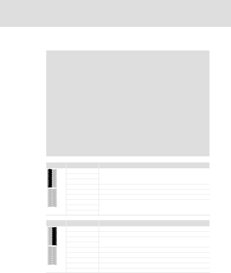
Displays |
|
|
|
|
|
|
|
|
|
|
|
|
|
|
|
Pos. |
Colour |
State |
Description |
|
|
|
|
|
|
On |
Drive−based safety has initialised without a fault. |
|
|
|
|
|
|
|
|
|
|
|
|
|
|
Blinking |
Drive−based safety has initialised without a fault. Internal |
|
|
|
|
|
|
communication to the standard device is not possible. |
|
|
|
|
|
MS |
|
|
|
|
|
|
|
Green |
|
|
|
|
|
|
|
Flashing |
Drive−based safety is in service status. |
|
|
|
||
|
(Module State) |
|
|
|
|||
|
|
For exiting, parameterise the drive−based safety. |
|
|
|
||
|
|
|
|
|
|
|
|
|
|
|
|
|
|
|
|
|
|
|
Off |
Drive−based safety is not initialised. |
|
|
|
|
|
|
Acknowledgement is not possible. |
|
|
|
|
|
|
|
|
|
|
|
|
|
|
|
|
|
|
|
|
|
EN |
Yellow |
On |
Controller enabled |
|
|
|
|
|
|
|
|
|
||
|
(Enable) |
Off |
Non−safe display "STO" |
|
|
|
|
|
|
|
|
|
|||
|
|
|
|
|
|
|
|
|
|
|
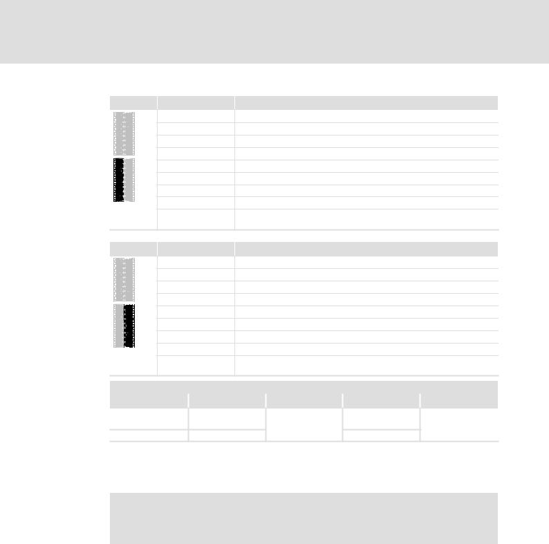
On |
System error |
|
|
|
|
|
|
|
|
|
|
|
|
ME |
Red |
Blinking |
Trouble |
|
|
|
|
|
|
|
|
|
||
|
(Module Error) |
Flashing |
Warning |
|
|
|
|
|
|
|
|
|
|||
|
|
|
|
|
|
|
|
|
|
|
Off |
Error−free operation |
|
|
|
|
|
|
|
|
|
|
|
|
|
|
On |
Request of an acknowledgement for the restart or the |
|
|
|
|
|
|
parameter set adoption |
|
|
|
|
|
|
|
|
|
|
|
|
|
AS |
|
|
|
|
|
|
|
Yellow |
Blinking |
SS1/STO active |
|
|
|
|
|
(Acknowledge Stop) |
|
|
|
|
|
|
|
|
Flashing |
SS2/SOS active |
|
|
|
|
|
|
|
|
|
|
||
|
|
|
|
|
|
|
|
|
|
|
Off |
No stop function active |
|
|
|
|
|
|
|
|
|
|
|
|
|
|
|
Safety bus error: |
|
|
|
|
|
|
On |
l Communication is not possible. |
|
|
|
|
BE |
Red |
|
l Acknowledgement is possible. |
|
|
|
|
(Bus Error) |
|
|
|
|
|
|
|
|
Blinking |
Safety bus error: no valid configuration. |
|
|
|
|
|
|
|
|
|
|
||
|
|
|
|
|
|
|
|
|
|
|
Off |
Safety bus: error−free operation. |
|
|
|
|
|
|
|
|
|
|
|
|
|
|
On |
Drive−based safety is not accepted by the standard device |
|
|
|
|
DE |
|
(see notes in the instructions for the standard device). |
|
|
|
|
|
Red |
|
|
|
|
||
|
|
|
|
|
|
||
|
(Drive Error) |
Off |
Drive−based safety is correctly recognised by the standard |
|
|
|
|
|
|
|
|
|
|||
|
|
|
device. |
|
|
|
|
|
|
|
|
|
|
|
|
|
Blinking: on/off every 0.5 s Flashing: on/off every 0.1/0.9 s |
|
|
|
|||
EDS94AYAE EN 7.0
l |
21 |
1 Safety engineering
Device modules SM301 safety module
Terminal assignment
} Danger!
Danger to life through improper installation
Improper installation of the safety engineering systems can cause anuncontrolled starting action of the drives.
Possible consequences:
ƒ Death or severe injuries
Protective measures:
Total cable length between X82 and its connected components (e.g. sensors, devices, ...) > 3 m:
ƒ Up to HW version 1A, a shielded laying system must be used for the cable between X82 and its connected components:
– The shield must at least cover the shield connection at the installation backplane.
– The shield should also cover the connected component if possible. ƒ From HW version 1A onwards, unshielded wiring is permissible.
Total cable length between X82 and its connected components (e.g. sensors, devices, ...) < 3 m:
ƒ Unshielded wiring is permissible.
X82.1 |
Labelling |
Description |
|
|
This part of the terminal strip is not assigned. |
|
GO |
GND SD−Out1 |
|
O1B |
Safe monitor SD−Out1, channel B |
|
O1A |
Safe monitor SD−Out1, channel A |
|
|
This part of the terminal strip is not assigned. |
X82.2 |
Labelling |
Description |
|
− |
GND external supply |
|
+ |
+24 V external supply via a safely separated power supply unit (SELV/PELV) |
|
GIR |
This part of the terminal strip is reserved. |
|
RI1 |
|
|
|
|
|
GO |
GND 24O |
|
24O |
+24 V external supply for the safe monitor SD−Out1 (SELV/PELV) |
|
AIE |
Error acknowledgement input ("Acknowledge In Error") |
|
CLA |
Clock output for passive sensors, channel A (Clock A) |
|
CLB |
Clock output for passive sensors, channel B (Clock B) |
22 |
l |
EDS94AYAE EN 7.0
Safety engineering |
1 |
Device modules
SM301 safety module
X82.3 |
Labelling |
Description |
|
|
|
|
GCL |
GND clock output |
|
|
|
|
GI2 |
GND SD−In2 |
|
|
|
|
I2B |
Sensor input SD−In2, channel B |
|
|
|
|
I2A |
Sensor input SD−In2, channel A |
|
|
|
|
GCL |
GND clock output |
|
|
|
|
GI1 |
GND SD−In1 |
|
|
|
|
I1B |
Sensor input SD−In1, channel B |
|
|
|
|
I1A |
Sensor input SD−In1, channel A |
|
|
|
|
AIS |
Restart acknowledgement input ("Acknowledge In Stop", 1−channel, |
|||
|
|
bridged to X82.4/AIS) |
|
|
|
X82.4 |
Labelling |
Description |
|
|
|
|
GCL |
GND clock output |
|
|
|
|
GI4 |
GND SD−In4 |
|
|
|
|
I4B |
Sensor input SD−In4, channel B |
|
|
|
|
I4A |
Sensor input SD−In4, channel A |
|
|
|
|
GCL |
GND clock output |
|
|
|
|
GI3 |
GND SD−In3 |
|
|
|
|
I3B |
Sensor input SD−In3, channel B |
|
|
|
|
I3A |
Sensor input SD−In3, channel A |
|
|
|
|
AIS |
Restart acknowledgement input ("Acknowledge In Stop", 1−channel, |
|||
|
|
bridged to X82.3/AIS) |
|
|
|
Cable cross−sections and tightening torques |
|
|
|
||
Type |
|
[mm2] |
[Nm] |
AWG |
[lb−in] |
Wire end ferrule, |
0.25 ... 0.75 |
|
24 ... 18 |
|
|
insulated |
|
Spring terminal |
Spring terminal |
||
|
|
|
|||
|
|
|
|
||
Rigid |
|
0.14 ... 1.5 |
|
26 ... 16 |
|
Stripping length or contact length: 9 mm
Insulated wire end ferrules according to DIN 46228, part 4, 0.5 mm2 or 0.75 mm2 − length L1 = 10 mm can be used.
) Note!
Provide for a sufficient strain relief, so that the terminals are not pulled from the plug connectors, in particular when you use rigid cables.
EDS94AYAE EN 7.0
l |
23 |

1 Safety engineering
Device modules SM301 safety module
1.2.3.4Technical data
24 V supply
The module and the safe output must be supplied with 24 V from safely separated power supply units. If electrical isolation is required, separate voltage supply lines must be used.
Detailed features of the 24−V supply
Terminal |
Specification |
[Unit] |
min. |
typ. |
max. |
|
+, − |
Supply voltage of the module via a safely separated |
[V] |
19,2 |
24 |
30 |
|
|
power supply unit (SELV/PELV) |
|
|
|
|
|
|
|
|
|
|
|
|
|
Input current |
[mA] |
|
|
350 |
|
|
|
|
|
|
|
|
24O, GO |
Supply voltage of the safe output via a safely |
[V] |
18 |
24 |
30 |
|
|
separated power supply unit (SELV/PELV) |
|
|
|
|
|
|
|
|
|
|
|
|
|
Input current |
[mA] |
|
|
1100 |
|
If the voltage of the SELV/PELV power supply unit can exceed 30 V in the event of an error, provide for an external fuse (¶1.1.8).
Inputs and output
The inputs and the output are isolated and designed for a low−voltage supply of 24 V DC. The digital inputs are protected against polarity reversal.
Detailed features of the safe inputs and the safe output
Terminal |
|
Specification |
[Unit] |
min. |
typ. |
max. |
|
I1A, I1B |
|
PLC input, IEC−61131−2, 24 V, type 1 |
|
|
|
|
|
I2A, I2B |
|
|
|
|
|
|
|
|
Low signal input voltage |
V |
−3 |
0 |
5 |
|
|
I3A, I3B |
|
|
|||||
|
|
|
|
|
|
|
|
|
Input current at low signal |
mA |
|
|
15 |
|
|
I4A, I4B |
|
|
|
|
|||
|
|
|
|
|
|
|
|
AIE, AIS |
|
High signal input voltage |
V |
15 |
24 |
30 |
|
|
|
|
|
|
|
|
|
|
|
Input current at high signal |
mA |
2 |
|
15 |
|
|
|
|
|
|
|
|
|
|
|
Input capacitance |
nF |
|
|
3.5 |
|
|
|
|
|
|
|
|
|
|
|
Repetition rate of the test pulses |
ms |
50 |
|
|
|
|
|
|
|
|
|
|
|
AIE, AIS |
|
Input delay (operating time) |
s |
0.3 |
|
10 |
|
|
|
|
|
|
|
|
|
CLA, CLB |
|
PLC output, IEC−61131−2, 24 V DC, 50 mA |
|
|
|
|
|
|
|
|
|
|
|
|
|
|
|
Low signal output voltage |
V |
|
0 |
0.8 |
|
|
|
|
|
|
|
|
|
|
|
High signal output voltage |
V |
17 |
24 |
30 |
|
|
|
|
|
|
|
|
|
|
|
Output current |
mA |
|
|
60 |
|
|
|
|
|
|
|
|
|
|
|
Cable capacity |
nF |
|
|
100 |
|
|
|
|
|
|
|
|
|
|
|
Cable resistance of a passive sensor |
W |
|
|
200 |
|
|
|
|
|
|
|
|
|
O1A, O1B |
|
PLC output, IEC−61131−2, 24 V DC |
|
|
|
|
|
|
|
|
|
|
|
|
|
|
|
Low signal output voltage |
V |
|
0 |
0.8 |
|
|
|
|
|
|
|
|
|
|
|
High signal output voltage |
V |
17 |
24 |
30 |
|
|
|
|
|
|
|
|
|
|
|
Output current |
mA |
|
|
500 |
|
|
|
|
|
|
|
|
|
|
|
Cable capacity |
nF |
|
|
100 |
|
|
|
|
|
|
|
|
|
|
|
Cable resistance |
W |
|
|
200 |
|
Tab. 1−1 |
Technical data |
|
|
|
|
|
|
The chapter "Response times" must be observed as well (¶1.8).
24 |
l |
EDS94AYAE EN 7.0

Safety engineering |
1 |
Device modules
SM301 safety module
1.2.3.5Example circuit
SM301
E94AYAE
X82.1
GO
O1B
O1A
X82.2
24 V ext.
- |
+ |
GO

24O  AIE
AIE 

 CLA
CLA
 CLB
CLB
|
|
GCL |
|
|
GI2 |
|
|
I2B |
|
|
I2A |
S2 |
|
GCL |
|
|
|
|
|
GI1 |
|
|
I1B |
|
|
I1A |
S1 |
K |
AIS |
|
GCL
S4
GI4
 I4B
I4B
 I4A
I4A
GCL
S3
GI3
 I3B
I3B
 I3A
I3A
 AIS
AIS 
|
X82.3 |
X82.4 |
|
|
SSP94SM360 |
Fig. 1−3 |
Wiring example |
|
|
E94AYAE |
SM301 safety module |
|
S1 |
passive sensor with channel A and B |
|
S2 |
|
|
|
|
|
S3 |
higher−level safety control (active sensor) |
|
S4 |
lightgrid (active sensor) |
|
24 V ext. |
24−V voltage supply of the module (SELV/PELV) |
|
• |
24−V voltage supply of the output (SELV/PELV) |
|
‚ |
safe output to higher−level safety control |
|
K |
to AIS of the next module |
EDS94AYAE EN 7.0
l |
25 |

1 Safety engineering
Device modules SM301 safety module
1.2.3.6Commissioning
ƒFor commissioning and safe parameter setting, the Lenze »Engineer« PC software from version 1.4 must be used.
If you select the safety module in the Project view, various tabs are available in the Operating range via which the safety module can be parameterised. In all other program parts the parameters of the safety module can only be read. Thus, the write access of these parameters (codes) is marked with }.
ƒSettings in or at the module:
–Safety address
–Safe parameter setting of the functions to be used
ƒRequired settings in the standard device:
–C00214, type of safety module
–Implementation of the SM301 into the drive application by evaluating the control information and status information.
ƒDuring commissioning and after the replacement of a module it is vital to check the safety function. Additional information contains the "Acceptance" chapter. (¶ 110).
26 |
l |
EDS94AYAE EN 7.0

Safety engineering |
1 |
Device modules
SM301 safety module
1.2.3.7Test certificate
SSP94TUEV3 _2010
Fig. 1−4 TÜV Certificate
The type test was carried out by ’TÜV Rheinland (Group)’ and confirmed with a certificate.
ƒ SM301 V1.0
Contents |
Specifications |
|
Test institute |
TÜV Rheinland Industrie Service GmbH, ASI range |
|
|
|
|
Test report |
968/EL 420.00/06 |
|
|
|
|
Test fundamentals |
EN 954−1, EN 60204−1, EN 50178, EN 61800−3, IEC 61508 Part 1−7 |
|
|
|
|
Object to be examined |
SM301, type E94AYAE VA1.0x of the 9400 Servo Drives series |
|
|
|
|
Test result |
The module meets the requirements according to EN 954−1, category 3. |
|
|
|
|
Special conditions |
The safety instructions in the corresponding user documentation must be |
|
|
observed. |
|
|
|
|
Place of issue |
Cologne |
|
|
|
|
Issue date |
01.08.2006 |
|
EDS94AYAE EN 7.0
l |
27 |

1 |
Safety engineering |
|
|
|
|
|
Device modules |
|
|
|
|
|
SM301 safety module |
|
|
|
|
|
|
ƒ from SM301 V1.1 |
|
|
|
|
|
|
|
|
|
|
|
Contents |
Specifications |
|
|
|
|
Test institute |
TÜV Rheinland Industrie Service GmbH, ASI range |
||
|
|
|
|
|
|
|
|
Test report |
968/EL 420.03/07 |
||
|
|
|
|
|
|
|
|
Test fundamentals |
EN 954−1, EN 60204−1, EN 50178, EN 61800−3, EN 61508 Part 1−7, |
||
|
|
|
EN ISO 13849−1, EN 62061 |
||
|
|
|
|
|
|
|
|
Object to be examined |
SM301, type E94AYAE VB1.1x of the 9400 Servo Drives series |
||
|
|
|
|
|
|
|
|
Test result |
The module meets the requirements according to |
||
|
|
|
l EN 954−1, category 3 |
||
|
|
|
l EN 61508, SIL 3 |
||
|
|
|
l EN ISO 13849−1, PL e |
||
|
|
|
|
|
|
|
|
Special conditions |
The safety instructions in the corresponding user documentation must be |
||
|
|
|
observed. |
||
|
|
|
|
|
|
|
|
Place of issue |
Cologne |
||
|
|
|
|
|
|
|
|
Issue date |
08.05.2007 |
|
|
|
|
ƒ from SM301 V1.2 |
|
|
|
|
|
|
|
||
|
|
Contents |
Specifications |
|
|
|
|
Test institute |
TÜV Rheinland Industrie Service GmbH, ASI range |
||
|
|
|
|
|
|
|
|
Test report |
968/EL 420.04/07 |
||
|
|
|
|
|
|
|
|
Test fundamentals |
EN 954−1, EN 60204−1, EN 50178, EN 61800−3, EN 61508 Part 1−7, |
||
|
|
|
EN ISO 13849−1, EN 62061 |
||
|
|
|
|
|
|
|
|
Object to be examined |
SM301, type E94AYAE of the Servo Drives 9400 series |
||
|
|
|
|
|
|
|
|
Test result |
The module meets the requirements according to |
||
|
|
|
l EN 954−1, category 3 |
||
|
|
|
l EN 61508, SIL 3 |
||
|
|
|
l EN ISO 13849−1, category 3/PL e |
||
|
|
|
|
|
|
|
|
Special conditions |
The safety instructions in the corresponding user documentation must be |
||
|
|
|
observed. |
||
|
|
|
|
|
|
|
|
Place of issue |
Cologne |
||
|
|
|
|
|
|
|
|
Issue date |
18.10.2007 |
|
|
28 |
l |
EDS94AYAE EN 7.0

Safety engineering |
1 |
Device modules |
|
SM301 safety module |
|
ƒ from SM301 V1.3
Contents |
Specifications |
|
Test institute |
TÜV Rheinland Industrie Service GmbH, ASI range |
|
|
|
|
Test report |
968/EL 420.07/10 |
|
|
|
|
Certification body |
NB 0035 |
|
|
|
|
Registration no. |
01/205/0718/10 |
|
|
|
|
Test fundamentals |
EN 60204−1, EN 61800−3, EN 61508 Part 1−7, EN ISO 13849−1, EN 62061, |
|
|
EN 61800−5−2, EN 61800−5−1 |
|
|
|
|
Object to be examined |
SM301, type E94AYAE of the Servo Drives 9400 series |
|
|
|
|
Test result |
The module meets the requirements according to |
|
|
l EN 61508, SIL 3 |
|
|
l EN ISO 13849−1, category 3/PL e |
|
|
|
|
Special conditions |
The safety instructions in the corresponding user documentation must be |
|
|
observed. |
|
|
|
|
Place of issue |
Berlin |
|
|
|
|
Issue date |
29.01.2010 |
|
|
|
|
Valid until |
29.01.2015 |
|
ƒ from SM301 V1.4
Contents |
Specifications |
|
Test institute |
TÜV Rheinland Industrie Service GmbH, ASI range |
|
|
|
|
Test report |
968/EL 420.08/10 |
|
|
|
|
Test fundamentals |
EN 60204−1, EN 61800−3, EN 61508 Part 1−7, EN ISO 13849−1, EN 62061, |
|
|
EN 61800−5−2, EN 61800−5−1 |
|
|
|
|
Object to be examined |
SM301, type E94AYAE of the Servo Drives 9400 series |
|
|
|
|
Test result |
The module meets the requirements according to |
|
|
l EN 61508, SIL 3 |
|
|
l EN ISO 13849−1, category 3/PL e |
|
|
|
|
Special conditions |
The safety instructions in the corresponding user documentation must be |
|
|
observed. |
|
|
|
|
Place of issue |
Cologne |
|
|
|
|
Issue date |
11.10.2010 |
|
EDS94AYAE EN 7.0
l |
29 |

1 Safety engineering
Device modules Safe inputs
1.2.4Safe inputs
1.2.4.1General
The following applies to the sensors at the SM301 V1.0:
ƒSensor type and sensor function can be parameterised in C15030, C15031 and C15032.
ƒA local evaluation is executed if corresponding parameters are set.
ƒIf a safety bus is activated, the sensor signals are sent as status information to the higher−level control.
ƒDeactivated sensor inputs must not be connected. The status of a non−connected input is in the OFF state.
ƒIf a signal is detected at deactivated sensor inputs during initialisation, the drive remains inhibited (STO).
ƒFaulty inputs are assessed as OFF state.
Additional conditions from SM301 V1.1 onwards:
ƒ With active cascading in C15035 the SD−In4 input cannot be used freely anymore.
Codes
Parameter: |
Name: |
Data type: |
Index: |
C15030 |
SD-In sensor type |
UNSIGNED_8 |
9545d = 2549h |
|
|
|
|
Configuration of the sensor types which are connected to the safe inputs.
Selection list (Lenze setting bold) |
|
Information |
|
|
|
|
|
0 |
Input deactivated |
|
|
|
|
|
|
1 |
Passive sensor |
|
|
|
|
|
|
2 |
Active sensor |
|
|
|
|
|
|
Subcodes |
|
|
Information |
|
|
|
|
C15030/1 |
|
|
SD-In1 sensor type |
|
|
|
|
C15030/2 |
|
|
SD-In2 sensor type |
|
|
|
|
C15030/3 |
|
|
SD-In3 sensor type |
|
|
|
|
C15030/4 |
|
|
SD-In4 sensor type |
|
|
|
|
þ Read access }Write access o Controller inhibit |
o PLC-STOP o No transfer |
||
C15031 |
SD-In sensor function |
|
|
UNSIGNED_8 |
9544d = 2548h |
Function configuration of the safe inputs.
lThe "operation mode selector" and "enable switch" functions may only be assigned to one of the four safe inputs.
Selection list (Lenze setting printed in bold) |
|
Information |
|
|
|
|
|
0 |
Free assignment |
|
Safety function set in C15032 |
|
|
|
|
1 |
Emergency stop |
|
Safe stop emergency function (SSE) |
|
|
|
|
2 |
Operation mode selector |
|
Safe operation mode selector (OMS) |
|
|
|
|
3 |
Enable switch |
|
Safe enable switch (ES) |
|
|
|
|
Subcodes |
|
|
Information |
|
|
|
|
C15031/1 |
|
|
SD-In1 sensor function |
|
|
|
|
C15031/2 |
|
|
SD-In2 sensor function |
|
|
|
|
C15031/3 |
|
|
SD-In3 sensor function |
|
|
|
|
C15031/4 |
|
|
SD-In4 sensor function |
|
|
|
|
þ Read access }Write access o Controller inhibit o PLC-STOP |
o No transfer |
||
30 |
l |
EDS94AYAE EN 7.0
Loading...