Lenze 8200 User Manual

L
Manual
Global Drive
PLC Developer Studio
Global Drive
Function library
Lenze8200Drive.lib
The function library Lenze8200Drive.lib can be used for the following Lenze PLCs:
|
Type |
from hardware version |
from software version |
|
|
|
|
9300 Servo PLC |
EVS93XX−xT |
6A |
6.0 |
|
|
|
|
Drive PLC |
EPL10200 |
1A |
6.0 |
|
|
|
|
ECSxA |
ECSxAxxx |
1C |
7.0 |
|
|
|
|
Important note:
The software is supplied to the user as described in this document. Any risks resulting from its quality or use remain the responsibility of the user. The user must provide all safety measures protecting against possible maloperation.
We do not take any liability for direct or indirect damage, e.g. profit loss, order loss or any loss regarding business.
ã 2002 Lenze Drive Systems GmbH
No part of this documentation may be copied or made available to third parties without the explicit written approval of Lenze Drive Systems GmbH.
All information given in this documentation has been carefully selected and tested for compliance with the hardware and software described. Nevertheless, discrepancies cannot be ruled out. We do not accept any responsibility or liability for any damage that may occur. Required corrections will be included in updates of this documentation.
All product names mentioned in this documentation are trademarks of the corresponding owners.
Version 1.0 03/2005

|
|
|
Function library Lenze8200Drive.lib |
|
|
|
|
|
Contents |
|
|
|
|
|
|||
1 Preface and general information . . . . . . . . . . . . . . . . . . . . . . . . . . . . . . . . . . . . . . . . . . . |
|
1−1 |
|||
|
1.1 |
About this Manual . . . . . . . . . . . . . . . . . . . . . . . . . . . . . . . . . . . . . . . . . . . . . . . . . . . . . . . . . . . . . . . . . |
|
1−1 |
|
|
|
1.1.1 |
Conventions used in this Manual . . . . . . . . . . . . . . . . . . . . . . . . . . . . . . . . . . . . . . . . . . . . . . . |
|
1−1 |
|
|
1.1.2 |
Layout of the descriptions . . . . . . . . . . . . . . . . . . . . . . . . . . . . . . . . . . . . . . . . . . . . . . . . . . . . |
|
1−2 |
|
|
1.1.3 |
Pictographs used in this Manual . . . . . . . . . . . . . . . . . . . . . . . . . . . . . . . . . . . . . . . . . . . . . . . |
|
1−2 |
|
|
1.1.4 |
Terminology used . . . . . . . . . . . . . . . . . . . . . . . . . . . . . . . . . . . . . . . . . . . . . . . . . . . . . . . . . . |
|
1−2 |
|
1.2 |
Version identifiers of the function library . . . . . . . . . . . . . . . . . . . . . . . . . . . . . . . . . . . . . . . . . . . . . . . . . |
|
1−3 |
|
2 |
Introduction |
. . . . . . . . . . . . . . . . . . . . . . . . . . . . . . . . . . . . . . . . . . . . . . . . . . . . . . . . . . . |
|
2−1 |
|
|
2.1 |
General . |
. . . . . . . . . . . . . . . . . . . . . . . . . . . . . . . . . . . . . . . . . . . . . . . . . . . . . . . . . . . . . . . . . . . . . . . . |
|
2−1 |
|
2.2 |
Frequency inverter parameterisation . . . . . . . . . . . . . . . . . . . . . . . . . . . . . . . . . . . . . . . . . . . . . . . . . . . . |
|
2−2 |
|
|
|
2.2.1 |
Assigning the system bus node addresses to the frequency inverters . . . . . . . . . . . . . . . . . . . . . |
|
2−3 |
|
|
2.2.2 |
Function block activation . . . . . . . . . . . . . . . . . . . . . . . . . . . . . . . . . . . . . . . . . . . . . . . . . . . . . |
|
2−3 |
|
2.3 |
Process data exchange with the frequency inverter . . . . . . . . . . . . . . . . . . . . . . . . . . . . . . . . . . . . . . . . . |
|
2−4 |
|
3 |
Functions/function blocks . . . . . . . . . . . . . . . . . . . . . . . . . . . . . . . . . . . . . . . . . . . . . . . . |
|
3−1 |
||
|
3.1 |
L_8200Parameter − Initialisation of codes . . . . . . . . . . . . . . . . . . . . . . . . . . . . . . . . . . . . . . . . . . . . . . . . |
|
3−2 |
|
|
3.2 |
L_8200Initialization − Frequency inverter initialisation . . . . . . . . . . . . . . . . . . . . . . . . . . . . . . . . . . . . . . . |
|
3−7 |
|
|
3.3 |
L_8200DataControl − Send/receive process data . . . . . . . . . . . . . . . . . . . . . . . . . . . . . . . . . . . . . . . . . . . |
|
3−10 |
|
|
3.4 |
L_8200CtrlWord − Selection of boolean control signals . . . . . . . . . . . . . . . . . . . . . . . . . . . . . . . . . . . . . . . |
|
3−15 |
|
|
3.5 |
L_8200StatusWord − Output of boolean status signals . . . . . . . . . . . . . . . . . . . . . . . . . . . . . . . . . . . . . . . |
|
3−16 |
|
l
Lenze8200Drive.lib EN 1.0 |
i |

Function library Lenze8200Drive.lib
Contents
ii |
Lenze8200Drive.lib EN 1.0 |
l |

Function library Lenze8200Drive.lib
Preface and general information
1 Preface and general information
1.1About this Manual
This Manual contains information about function library Lenze8200Drive.lib for the Drive PLC Developer Studio.
·The function blocks of function library Lenze8200Drive.lib can be used to exchange data between the PLC and one or more frequency inverters of the 8200 series via the system bus
(CAN).
·It is possible to assign up to 45 frequency inverter parameters (codes) from the PLC and cyclically exchange process data with the frequency inverter.
1.1.1Conventions used in this Manual
This Manual uses the following conventions to distinguish between different types of information:
Variable identifiers
are written in italics in the explanation:
· "Use bReset..."
Tip!
Information about the conventions used for the variables of the Lenze system blocks, function blocks and functions can be found in the appendix of the DDS online documentation "Introduction into IEC61131−3 programming". The conventions ensure universal and uniform labelling and make reading the PLC program easier.
Lenze functions/function blocks
can be recognized by their names. They always begin with an "L_":
· "With the function L_TBConvBitsToByte..."
Program listings
are written in "Courier", keywords are printed in bold:
· " IF (ReturnValue < 0) THEN..."
l
Lenze8200Drive.lib EN 1.0 |
1−1 |

Function library Lenze8200Drive.lib
Preface and general information
1.1.2Layout of the descriptions
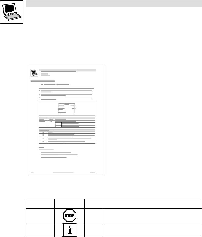
All function/function block and system block descriptions contained in this Manual have the same structure:
|
|
Function |
Function block (FB)/ |
|||
|
|
|
|
System block (SB) |
||
|
|
|
|
|||
|
• |
Headline stating the function and the function identifier |
||||
|
|
|
|
|
||
|
‚ |
Declaration of the function: |
− |
|
||
• |
|
· Data type of the return value |
|
|
||
|
· |
Function identifier |
|
|
||
|
|
|
|
|||
‚ |
|
· |
List of transfer parameters |
|
|
|
ƒ |
|
|
|
|
|
|
ƒ |
Short description of the most important properties |
|||||
|
||||||
|
|
|
|
|||
|
„ |
Function chart including all |
FB/SB chart including all |
|||
„ |
|
associated variables |
associated variables |
|||
|
· |
Transfer parameters |
· |
Input variables |
||
|
|
|||||
|
|
· |
Return value |
· |
Output variables |
|
|
|
|
|
|||
… |
… |
Table giving information about the |
Table giving information about the |
|||
|
|
transfer parameters: |
input and output variables: |
|||
|
|
· |
Identifier |
· |
Identifier |
|
|
|
· |
Data type |
· |
Data type |
|
† |
|
· |
Possible settings |
· |
Type of variable |
|
|
|
· |
Info |
· |
Possible settings |
|
|
|
|
|
· |
Info |
|
|
|
|
|
|
||
‡ |
† |
Table giving information about the |
− |
|
||
|
return value: |
|
|
|||
|
|
|
|
|||
|
|
· Data type of the return value |
|
|
||
|
|
· Possible return values and their |
|
|
||
|
|
|
meaning: |
|
|
|
|
|
|
|
|
||
|
‡ |
Additional information |
|
|
||
|
|
(Notes, tips, application examples, etc.) |
|
|||
|
|
|
|
|
|
|
1.1.3Pictographs used in this Manual
Use of |
Signal words |
|
pictograms |
|
|
Warning of |
Stop! |
Warns of potential damage to material. |
material damage |
|
Possible consequences if disregarded: |
|
|
Damage to the controller/drive system or its environment. |
Other notes |
Tip! |
Indicates a tip or note. |
|
Note! |
|
1.1.4Terminology used
Term |
In the following text used for |
|
|
|
|
DDS |
Drive PLC Developer Studio |
|
|
|
|
FB |
Function block |
|
|
|
|
GDC |
Global Drive Control (parameterization program from Lenze) |
|
|
|
|
Parameter codes |
Codes for setting the functionality of a function block |
|
|
|
|
PLC |
· |
9300 Servo PLC |
|
· |
Drive PLC |
|
· ECSxA "Application" axis module |
|
|
|
|
SB |
System block |
|
|
|
|
1−2 |
Lenze8200Drive.lib EN 1.0 |
l |

Function library Lenze8200Drive.lib
Preface and general information
1.2Version identifiers of the function library
The version of the function library can be found under the global constant
C_w[Function library name]Version .
Version identifiers as of PLC software version 7.x:
Constant |
Meaning |
Example |
|
|
|
|
value |
|
|
|
|
||
|
|
|
|
|
|
|
C_w[FunctionLibraryName]VersionER |
External Release |
01 |
|
|
|
|
|
|
|
|
|||
|
|
|
|
|
|
|
C_w[FunctionLibraryName]VersionEL |
External Level |
05 |
|
|
|
|
|
|
|
|
|||
|
|
|
|
|
|
|
C_w[FunctionLibraryName]VersionIR |
Internal Release |
00 |
|
|
|
|
|
|
|
|
|||
|
|
|
|
|
|
|
C_w[FunctionLibraryName]VersionBN |
Build No. |
00 |
|
|
|
|
|
|
|
|
|||
|
|
|
|
|
|
|
|
|
|
|
|
|
|
Version: 01 05 00 00
The value of this constant is a hexadecimal code.
· In the example, "01050000" stands for version "1.05".
l
Lenze8200Drive.lib EN 1.0 |
1−3 |

Function library Lenze8200Drive.lib
Preface and general information
1−4 |
Lenze8200Drive.lib EN 1.0 |
l |

2
2.1
Function library Lenze8200Drive.lib
Introduction
Introduction
General
Integrate function library Lenze8200Drive.lib in your PLC program to make frequency inverter control easier.
Two function blocks are required for this:
1.A function block for the parameterisation of the frequency inverter.
2.Another function block for process data exchange between PLC and frequency inverter. The parameters can be set via the PLC program. It is possible to select up to 45 parameters.
Parameterisation concepts
The following parameterisation concepts are supported:
·Parameterisation through direct instructions in the FBs
·Parameterisation by means of codes ("online" parameterisation possible)
Note!
The frequency inverter must meet the following conditions for frequency inverter control from the PLC:
·The factory settings have been loaded.
(For the 8200vector frequency inverter, e. g. under code C0002)
·The system bus node address is correct.
(For the 8200vector frequency inverter, e. g. under code C0350)
·The new communication settings of the system bus interface have been accepted by a Reset−Node.
(For the 8200vector frequency inverter, e. g. under code C0358)
Tip!
Detailed information about the system bus (CAN) and function library LenzeCanDrv.lib can be found in the Manual "System bus (CAN) for Lenze PLC devices".
l
Lenze8200Drive.lib EN 1.0 |
2−1 |
 Loading...