


i700
Table of contents
 Loading...
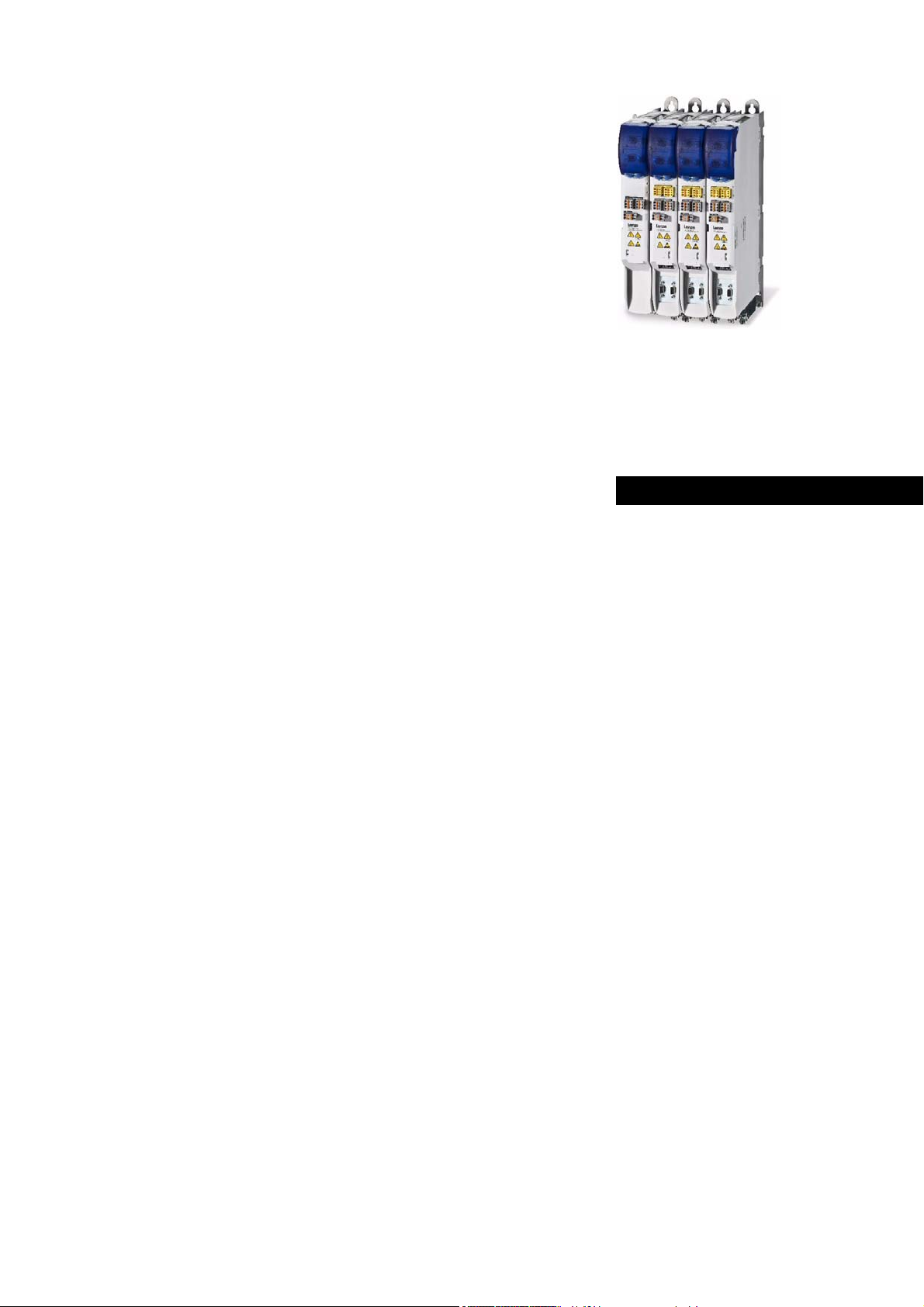
L
Ä.J(yä
13410788
i700
Inverter
i700 servo inverter _ _ _ _ _ _ _ _ _ _ _ _ _ _ _
Reference manual EN
E70ACM...

Contents
2 Lenze · i700 servo inverter · Reference manual · DMS 1.5 EN · 03/2014 · TD05
_ _ _ _ _ _ _ _ _ _ _ _ _ _ _ _ _ _ _ _ _ _ _ _ _ _ _ _ _ _ _ _ _ _ _ _ _ _ _ _ _ _ _ _ _ _ _ _ _ _ _ _ _ _ _ _ _ _ _ _ _ _ _ _
1 About this documentation _ _ _ _ _ _ _ _ _ _ _ _ _ _ _ _ _ _ _ _ _ _ _ _ _ _ _ _ _ _ _ _ _ _ _ _ _ _ _ 12
1.1 Conventions used _ _ _ _ _ _ _ _ _ _ _ _ _ _ _ _ _ _ _ _ _ _ _ _ _ _ _ _ _ _ _ _ _ _ _ _ _ _ _ _ _ _ _ _ 13
1.2 Terminology used _ _ _ _ _ _ _ _ _ _ _ _ _ _ _ _ _ _ _ _ _ _ _ _ _ _ _ _ _ _ _ _ _ _ _ _ _ _ _ _ _ _ _ _ 14
1.3 Definition of notes used _ _ _ _ _ _ _ _ _ _ _ _ _ _ _ _ _ _ _ _ _ _ _ _ _ _ _ _ _ _ _ _ _ _ _ _ _ _ _ _ _ 15
1.4 Structure of the parameter descriptions _ _ _ _ _ _ _ _ _ _ _ _ _ _ _ _ _ _ _ _ _ _ _ _ _ _ _ _ _ _ _ _ 16
2 Parameter handling _ _ _ _ _ _ _ _ _ _ _ _ _ _ _ _ _ _ _ _ _ _ _ _ _ _ _ _ _ _ _ _ _ _ _ _ _ _ _ _ _ _ _ 18
2.1 Parameter transfer during initialisation _ _ _ _ _ _ _ _ _ _ _ _ _ _ _ _ _ _ _ _ _ _ _ _ _ _ _ _ _ _ _ _ 18
2.2 Storage parameter set (par001.*) and total parameter set (par000.*) _ _ _ _ _ _ _ _ _ _ _ _ _ _ _ _ 19
2.2.1 Saving a parameter set from the i700 to a file (export) _ _ _ _ _ _ _ _ _ _ _ _ _ _ _ _ _ _ 20
2.2.2 Loading the stored parameter set to the i700 (import) _ _ _ _ _ _ _ _ _ _ _ _ _ _ _ _ _ _ 20
2.2.3 Monitoring of the parameter import (error report) _ _ _ _ _ _ _ _ _ _ _ _ _ _ _ _ _ _ _ _ _ 20
2.3 Cyclic redundancy check (CRC) - parameter set comparison on the basis of the checksum _ _ _ _ _ 21
0x2030 - Parameter set: Validity check (CRC)
3 Communication with the controller _ _ _ _ _ _ _ _ _ _ _ _ _ _ _ _ _ _ _ _ _ _ _ _ _ _ _ _ _ _ _ _ _ _ 22
3.1 Acceleration of the system (initialisation) _ _ _ _ _ _ _ _ _ _ _ _ _ _ _ _ _ _ _ _ _ _ _ _ _ _ _ _ _ _ _ 22
3.2 Process data (cyclic PDO transfer) and PDO mapping _ _ _ _ _ _ _ _ _ _ _ _ _ _ _ _ _ _ _ _ _ _ _ _ _ 24
3.2.1 Synchronisation with "Distributed clocks" (DC) _ _ _ _ _ _ _ _ _ _ _ _ _ _ _ _ _ _ _ _ _ _ _ 25
3.3 Parameter data transfer (SDO communication) _ _ _ _ _ _ _ _ _ _ _ _ _ _ _ _ _ _ _ _ _ _ _ _ _ _ _ _ 26
3.3.1 Object directory _ _ _ _ _ _ _ _ _ _ _ _ _ _ _ _ _ _ _ _ _ _ _ _ _ _ _ _ _ _ _ _ _ _ _ _ _ _ _ _ 26
3.3.2 SDO abort codes _ _ _ _ _ _ _ _ _ _ _ _ _ _ _ _ _ _ _ _ _ _ _ _ _ _ _ _ _ _ _ _ _ _ _ _ _ _ _ 27
3.3.3 ESI: EtherCAT Slave Information file (device description) _ _ _ _ _ _ _ _ _ _ _ _ _ _ _ _ _ 27
3.4 Activating the control via PDO _ _ _ _ _ _ _ _ _ _ _ _ _ _ _ _ _ _ _ _ _ _ _ _ _ _ _ _ _ _ _ _ _ _ _ _ _ 28
0x2824 | 0x3024 - Device control via PDO: Activation
3.5 Lenze control and status word _ _ _ _ _ _ _ _ _ _ _ _ _ _ _ _ _ _ _ _ _ _ _ _ _ _ _ _ _ _ _ _ _ _ _ _ _ 28
0x2830 | 0x3030 - Lenze control word
0x2831 | 0x3031 - Lenze status word
0x2833 | 0x3033 - Lenze statusword 2
3.6 Ethernet over EtherCAT (EoE) _ _ _ _ _ _ _ _ _ _ _ _ _ _ _ _ _ _ _ _ _ _ _ _ _ _ _ _ _ _ _ _ _ _ _ _ _ _ 31
3.6.1 System architecture _ _ _ _ _ _ _ _ _ _ _ _ _ _ _ _ _ _ _ _ _ _ _ _ _ _ _ _ _ _ _ _ _ _ _ _ _ 31
3.6.2 Supported protocols and services _ _ _ _ _ _ _ _ _ _ _ _ _ _ _ _ _ _ _ _ _ _ _ _ _ _ _ _ _ _ 32
3.6.3 Display of EoE-specific information _ _ _ _ _ _ _ _ _ _ _ _ _ _ _ _ _ _ _ _ _ _ _ _ _ _ _ _ _ 32
0x2020 - EoE information
3.6.4 GCI-SDO communication (TCP port 9410) _ _ _ _ _ _ _ _ _ _ _ _ _ _ _ _ _ _ _ _ _ _ _ _ _ _ 33
3.6.4.1 Structure of the EtherCAT data telegram _ _ _ _ _ _ _ _ _ _ _ _ _ _ _ _ _ _ _ 34
3.6.4.2 Assignment of user data areas P0 ... P4 _ _ _ _ _ _ _ _ _ _ _ _ _ _ _ _ _ _ _ _ 36
3.6.4.3 Error codes _ _ _ _ _ _ _ _ _ _ _ _ _ _ _ _ _ _ _ _ _ _ _ _ _ _ _ _ _ _ _ _ _ _ _ 37
3.6.4.4 Telegram example 1:
Querying the heatsink temperature (read request) _ _ _ _ _ _ _ _ _ _ _ _ _ 38
3.6.4.5 Telegram example 2:
Querying the software version of the i700 (read request) _ _ _ _ _ _ _ _ _ _ 40
3.6.4.6 Telegram example 3:
Setting the LV warning threshold in the i700 (write request) _ _ _ _ _ _ _ _ 42
4 Device settings _ _ _ _ _ _ _ _ _ _ _ _ _ _ _ _ _ _ _ _ _ _ _ _ _ _ _ _ _ _ _ _ _ _ _ _ _ _ _ _ _ _ _ _ _ _ 44
4.1 Behaviour in case of error _ _ _ _ _ _ _ _ _ _ _ _ _ _ _ _ _ _ _ _ _ _ _ _ _ _ _ _ _ _ _ _ _ _ _ _ _ _ _ _ 44
0x10F1 - ECAT: Behaviour in case of error
4.2 Device identification data _ _ _ _ _ _ _ _ _ _ _ _ _ _ _ _ _ _ _ _ _ _ _ _ _ _ _ _ _ _ _ _ _ _ _ _ _ _ _ _ 46
0x2000 - Device: Data
0x2001 - Device: Name
4.3 Function "Optical device recognition" _ _ _ _ _ _ _ _ _ _ _ _ _ _ _ _ _ _ _ _ _ _ _ _ _ _ _ _ _ _ _ _ _ 46
0x2021 - Device: Optical recognition
4.4 Device commands _ _ _ _ _ _ _ _ _ _ _ _ _ _ _ _ _ _ _ _ _ _ _ _ _ _ _ _ _ _ _ _ _ _ _ _ _ _ _ _ _ _ _ _ 47
0x2022 - Device command
Contents

Lenze · i700 servo inverter · Reference manual · DMS 1.5 EN · 03/2014 · TD05 3
Contents
_ _ _ _ _ _ _ _ _ _ _ _ _ _ _ _ _ _ _ _ _ _ _ _ _ _ _ _ _ _ _ _ _ _ _ _ _ _ _ _ _ _ _ _ _ _ _ _ _ _ _ _ _ _ _ _ _ _ _ _ _ _ _ _
4.5 Monitoring of the DC-bus voltage _ _ _ _ _ _ _ _ _ _ _ _ _ _ _ _ _ _ _ _ _ _ _ _ _ _ _ _ _ _ _ _ _ _ _ 48
0x2540 - Device: Voltage values
4.6 Real-time information (distributed clock) _ _ _ _ _ _ _ _ _ _ _ _ _ _ _ _ _ _ _ _ _ _ _ _ _ _ _ _ _ _ _ 50
0x2580 - ECAT DC: Real-time information
5 Motor control & motor settings _ _ _ _ _ _ _ _ _ _ _ _ _ _ _ _ _ _ _ _ _ _ _ _ _ _ _ _ _ _ _ _ _ _ _ _ 52
5.1 Required commissioning steps (short overview) _ _ _ _ _ _ _ _ _ _ _ _ _ _ _ _ _ _ _ _ _ _ _ _ _ _ _ _ 54
5.1.1 Servo control for synchronous motor (SM) _ _ _ _ _ _ _ _ _ _ _ _ _ _ _ _ _ _ _ _ _ _ _ _ _ 54
5.1.2 Servo control for asynchronous motor (ASM) _ _ _ _ _ _ _ _ _ _ _ _ _ _ _ _ _ _ _ _ _ _ _ _ 55
5.1.3 V/f characteristic control for asynchronous motor (ASM) _ _ _ _ _ _ _ _ _ _ _ _ _ _ _ _ _ 56
5.2 Commissioning functions (short overview) _ _ _ _ _ _ _ _ _ _ _ _ _ _ _ _ _ _ _ _ _ _ _ _ _ _ _ _ _ _ 57
0x2822 | 0x3022 - Axis command
0x2823 | 0x3023 - Axis command: Progress
0x2825 | 0x3025 - Axis: Operating mode
0x2832 | 0x3032 - Identification: Status word
5.2.1 Enable/inhibit operation via control word _ _ _ _ _ _ _ _ _ _ _ _ _ _ _ _ _ _ _ _ _ _ _ _ _ 59
5.2.2 Saving changed parameters safe against mains failure _ _ _ _ _ _ _ _ _ _ _ _ _ _ _ _ _ _ 60
5.3 Wiring check by means of manual test modes _ _ _ _ _ _ _ _ _ _ _ _ _ _ _ _ _ _ _ _ _ _ _ _ _ _ _ _ _ 61
0x2835 | 0x3035 - Manual test mode: Settings
5.3.1 Manual test mode "voltage/frequency" _ _ _ _ _ _ _ _ _ _ _ _ _ _ _ _ _ _ _ _ _ _ _ _ _ _ _ 62
5.3.2 Manual test mode "current/frequency" _ _ _ _ _ _ _ _ _ _ _ _ _ _ _ _ _ _ _ _ _ _ _ _ _ _ _ 63
5.4 Manual control _ _ _ _ _ _ _ _ _ _ _ _ _ _ _ _ _ _ _ _ _ _ _ _ _ _ _ _ _ _ _ _ _ _ _ _ _ _ _ _ _ _ _ _ _ 65
0x2836 | 0x3036 - Manual jog: Settings
5.5 Setting the control mode _ _ _ _ _ _ _ _ _ _ _ _ _ _ _ _ _ _ _ _ _ _ _ _ _ _ _ _ _ _ _ _ _ _ _ _ _ _ _ _ 69
0x2C00 | 0x3400 - Motor control
5.6 Accepting/adapting plant parameters _ _ _ _ _ _ _ _ _ _ _ _ _ _ _ _ _ _ _ _ _ _ _ _ _ _ _ _ _ _ _ _ _ 70
5.7 Compensating for inverter influence on output voltage _ _ _ _ _ _ _ _ _ _ _ _ _ _ _ _ _ _ _ _ _ _ _ 71
0x2DE0 | 0x35E0 - Advanced settings
0x2947 | 0x3147 - Inverter characteristic: Voltage grid points (y)
5.8 Setting the motor parameters for the servo control _ _ _ _ _ _ _ _ _ _ _ _ _ _ _ _ _ _ _ _ _ _ _ _ _ _ 75
5.8.1 Lenze motor: Easy loading of motor data from the catalogue via the »PLC-Designer« _ _ 75
5.8.2 Motors of other manufacturers or no catalogue data available: Three possibilities to create the
setting _ _ _ _ _ _ _ _ _ _ _ _ _ _ _ _ _ _ _ _ _ _ _ _ _ _ _ _ _ _ _ _ _ _ _ _ _ _ _ _ _ _ _ _ _ 75
0x2C08 | 0x3408 - motor: Setting method - motor parameters
5.8.2.1 Enter motor nameplate data _ _ _ _ _ _ _ _ _ _ _ _ _ _ _ _ _ _ _ _ _ _ _ _ _ _ 76
5.8.2.2 Set motor parameters manually _ _ _ _ _ _ _ _ _ _ _ _ _ _ _ _ _ _ _ _ _ _ _ _ 76
5.8.2.3 Determine motor parameters automatically via "motor parameter identification"
78
5.8.3 Motor parameters (object descriptions) _ _ _ _ _ _ _ _ _ _ _ _ _ _ _ _ _ _ _ _ _ _ _ _ _ _ _ 81
0x2C01 | 0x3401 - Motor: Common parameters
0x2C02 | 0x3402 - Motor (ASM): Parameter
0x2C03 | 0x3403 - Motor (SM): Parameter
0x6075 | 0x6875 - Motor rated current
0x6076 | 0x6876 - Motor rated torque
5.9 Setting the feedback system for the servo control _ _ _ _ _ _ _ _ _ _ _ _ _ _ _ _ _ _ _ _ _ _ _ _ _ _ 85
5.9.1 General settings _ _ _ _ _ _ _ _ _ _ _ _ _ _ _ _ _ _ _ _ _ _ _ _ _ _ _ _ _ _ _ _ _ _ _ _ _ _ _ 86
0x2C45 | 0x3445 - open circuit in the feedback system: Response
0x2C46 | 0x3446 - feedback system: Specifiable number of revolutions
0x2C5F | 0x345F - Feedback system: Parameter CRC
5.9.2 Settings for "resolver" version _ _ _ _ _ _ _ _ _ _ _ _ _ _ _ _ _ _ _ _ _ _ _ _ _ _ _ _ _ _ _ _ 87
0x2C43 | 0x3443 - Resolver: Number of pole pairs
0x2C44 | 0x3444 - Resolver error compensation: Parameter
5.9.3 Settings for "encoder" version _ _ _ _ _ _ _ _ _ _ _ _ _ _ _ _ _ _ _ _ _ _ _ _ _ _ _ _ _ _ _ _ 89
0x2C40 | 0x3440 - Encoder: Type
0x2C42 | 0x3442 - Encoder: Parameter

Contents
4 Lenze · i700 servo inverter · Reference manual · DMS 1.5 EN · 03/2014 · TD05
_ _ _ _ _ _ _ _ _ _ _ _ _ _ _ _ _ _ _ _ _ _ _ _ _ _ _ _ _ _ _ _ _ _ _ _ _ _ _ _ _ _ _ _ _ _ _ _ _ _ _ _ _ _ _ _ _ _ _ _ _ _ _ _
5.9.4 Additional settings for SinCos absolute value encoders with HIPERFACE® protocol _ _ _ 91
0x2C41 | 0x3441 - Hiperface: Parameter
5.9.5 Detection of changed settings of the feedback system _ _ _ _ _ _ _ _ _ _ _ _ _ _ _ _ _ _ 94
5.10 Synchronous motor (SM): Pole position identification _ _ _ _ _ _ _ _ _ _ _ _ _ _ _ _ _ _ _ _ _ _ _ _ 95
5.10.1 Monitoring of the pole position identification _ _ _ _ _ _ _ _ _ _ _ _ _ _ _ _ _ _ _ _ _ _ _ 96
0x2C60 | 0x3460 - Monitoring of pole position identification: Response
5.10.2 Pole position identification PPI (360°) _ _ _ _ _ _ _ _ _ _ _ _ _ _ _ _ _ _ _ _ _ _ _ _ _ _ _ _ 96
0x2C61 | 0x3461 - Pole position identification PPI (360°)
5.10.3 Pole position identification PPI (min. movement) _ _ _ _ _ _ _ _ _ _ _ _ _ _ _ _ _ _ _ _ _ 99
0x2C62 | 0x3462 - Pole position identification PPI (min. movement)
5.10.4 Pole position identification PPI (without movement) _ _ _ _ _ _ _ _ _ _ _ _ _ _ _ _ _ _ _ 102
0x2C63 | 0x3463 - pole position identification PLI (without movement)
5.11 Setting control loops _ _ _ _ _ _ _ _ _ _ _ _ _ _ _ _ _ _ _ _ _ _ _ _ _ _ _ _ _ _ _ _ _ _ _ _ _ _ _ _ _ _ 105
5.11.1 Setting and optimising the current controller _ _ _ _ _ _ _ _ _ _ _ _ _ _ _ _ _ _ _ _ _ _ _ 105
0x2941 | 0x3141 - Current controller: Feedforward control
0x2942 | 0x3142 - Current controller: Parameter
0x2943 | 0x3143 - Motor: Current setpoint - filter time
5.11.1.1 Manual test mode "Current pulse" _ _ _ _ _ _ _ _ _ _ _ _ _ _ _ _ _ _ _ _ _ _ 108
5.11.2 Determining the total moment of inertia _ _ _ _ _ _ _ _ _ _ _ _ _ _ _ _ _ _ _ _ _ _ _ _ _ _ 111
0x2910 | 0x3110 - Moments of inertia
5.11.3 Setting the speed controller _ _ _ _ _ _ _ _ _ _ _ _ _ _ _ _ _ _ _ _ _ _ _ _ _ _ _ _ _ _ _ _ _ 113
0x2900 | 0x3100 - Speed controller: Parameter
0x2901 | 0x3101 - Speed controller: Gain - adaptation
0x2902 | 0x3102 - Speed controller: Load starting value
0x2903 | 0x3103 - Speed: Speed setpoint - filter time
0x2904 | 0x3104 - Speed: Actual speed - filter time
5.11.4 Setting the position controller _ _ _ _ _ _ _ _ _ _ _ _ _ _ _ _ _ _ _ _ _ _ _ _ _ _ _ _ _ _ _ _ 116
0x2980 | 0x3180 - Position controller: Gain
0x2981 | 0x3181 - Position controller: Gain - adaptation
0x2982 | 0x3182 - Position controller: Output signal limitation
0x2983 | 0x3183 - Position: Select a new actual position
0x2984 | 0x3184 - Determine target position: Mode
5.11.5 Setting the field controller (ASM) _ _ _ _ _ _ _ _ _ _ _ _ _ _ _ _ _ _ _ _ _ _ _ _ _ _ _ _ _ _ 118
0x29C0 | 0x31C0 - Field controller: Parameter
5.11.6 Setting the field weakening controller (ASM) _ _ _ _ _ _ _ _ _ _ _ _ _ _ _ _ _ _ _ _ _ _ _ _ 119
0x29E0 | 0x31E0 - Field weakening controller: Parameter
0x29E1 | 0x31E1 - field: Field set value limitation
0x29E2 | 0x31E2 - DC link circuit voltage: Filter time
0x29E3 | 0x31E3 - motor: Actual voltage - filter time
0x29E4 | 0x31E4 - Voltage reserve range
5.11.7 Field weakening operation - synchronous motor (SM) _ _ _ _ _ _ _ _ _ _ _ _ _ _ _ _ _ _ _ 121
5.12 Fine adjustment des motor model _ _ _ _ _ _ _ _ _ _ _ _ _ _ _ _ _ _ _ _ _ _ _ _ _ _ _ _ _ _ _ _ _ _ _ 122
5.12.1 Correction of the stator leakage inductance (Lss)... _ _ _ _ _ _ _ _ _ _ _ _ _ _ _ _ _ _ _ _ _ 122
0x2C04 | 0x3404 - Motor: Lss saturation characteristic - inductance grid points (y)
0x2C05 | 0x3405 - Motor: Lss saturation charcteristic - reference for current grid points (x)
5.12.1.1 Example for determining the saturation characteristic _ _ _ _ _ _ _ _ _ _ _ 125
5.12.2 Synchronous motor (SM): Compensating for temperature and current influences _ _ _ 128
0x2C06 | 0x3406 - Motor (SM): Magnet characteristic (current) - grid points
5.12.3 Asynchronous motor (ASM): Identifying the Lh saturation characteristic _ _ _ _ _ _ _ _ _ 129
0x2C07 | 0x3407 - Motor (ASM): Lh saturation characteristic - inductance grid points (y)
5.12.4 Estimating the optimal magnetising current _ _ _ _ _ _ _ _ _ _ _ _ _ _ _ _ _ _ _ _ _ _ _ _ 131

Lenze · i700 servo inverter · Reference manual · DMS 1.5 EN · 03/2014 · TD05 5
Contents
_ _ _ _ _ _ _ _ _ _ _ _ _ _ _ _ _ _ _ _ _ _ _ _ _ _ _ _ _ _ _ _ _ _ _ _ _ _ _ _ _ _ _ _ _ _ _ _ _ _ _ _ _ _ _ _ _ _ _ _ _ _ _ _
5.13 Parameterising filter elements in the setpoint path _ _ _ _ _ _ _ _ _ _ _ _ _ _ _ _ _ _ _ _ _ _ _ _ _ _ 132
5.13.1 Jerk limitation _ _ _ _ _ _ _ _ _ _ _ _ _ _ _ _ _ _ _ _ _ _ _ _ _ _ _ _ _ _ _ _ _ _ _ _ _ _ _ _ _ 132
0x2945 | 0x3145 - Torque: Setpoint jerk limitation
5.13.2 Notch filters (band-stop filters) _ _ _ _ _ _ _ _ _ _ _ _ _ _ _ _ _ _ _ _ _ _ _ _ _ _ _ _ _ _ _ 132
0x2944 | 0x3144 - Torque: Notch filter setpoint torque
5.14 Parameterising the V/f characteristic control _ _ _ _ _ _ _ _ _ _ _ _ _ _ _ _ _ _ _ _ _ _ _ _ _ _ _ _ _ 136
5.14.1 Defining the V/f characteristic shape _ _ _ _ _ _ _ _ _ _ _ _ _ _ _ _ _ _ _ _ _ _ _ _ _ _ _ _ 137
0x2B00 | 0x3300 - VFC: V/f characteristic - shape
0x2B01 | 0x3301 - VFC: V/f characteristic - define reference point
0x2B02 | 0x3302 - VFC: User-definable V/f characteristic - frequency grid points (x)
0x2B03 | 0x3303 - VFC: User-definable V/f characteristic - voltage grid points (y)
5.14.2 Activating the voltage vector control (lmin controller) _ _ _ _ _ _ _ _ _ _ _ _ _ _ _ _ _ _ _ 140
0x2B04 | 0x3304 - VFC: Voltage vector control - setpoint current
0x2B05 | 0x3305 - VFC: Voltage vector control parameter
5.14.3 Setting the voltage boost _ _ _ _ _ _ _ _ _ _ _ _ _ _ _ _ _ _ _ _ _ _ _ _ _ _ _ _ _ _ _ _ _ _ 141
0x2B06 | 0x3306 - VFC: Voltage boost
5.14.4 Setting the load adjustment _ _ _ _ _ _ _ _ _ _ _ _ _ _ _ _ _ _ _ _ _ _ _ _ _ _ _ _ _ _ _ _ _ 142
0x2B07 | 0x3307 - VFC: Load adjustment parameter
5.14.5 Defining the behaviour at the current limit (Imax controller) _ _ _ _ _ _ _ _ _ _ _ _ _ _ _ 143
0x2B08 | 0x3308 - VFC: Imax controller - Parameter
5.14.6 Setting the slip compensation _ _ _ _ _ _ _ _ _ _ _ _ _ _ _ _ _ _ _ _ _ _ _ _ _ _ _ _ _ _ _ _ 145
0x2B09 | 0x3309 - VFC: Slip compensation - Parameter
5.14.7 Setting the oscillation damping _ _ _ _ _ _ _ _ _ _ _ _ _ _ _ _ _ _ _ _ _ _ _ _ _ _ _ _ _ _ _ 146
0x2B0A | 0x330A - VFC: Oscillation damping - Parameter
5.14.8 Optimising pull-out slip limitation _ _ _ _ _ _ _ _ _ _ _ _ _ _ _ _ _ _ _ _ _ _ _ _ _ _ _ _ _ 148
0x2B0C | 0x330C - VFC: Override point of field weakening
5.14.9 Display parameter _ _ _ _ _ _ _ _ _ _ _ _ _ _ _ _ _ _ _ _ _ _ _ _ _ _ _ _ _ _ _ _ _ _ _ _ _ _ 148
0x2B0B | 0x330B - VFC: Setpoint frequency
5.14.10 "Flying restart" function _ _ _ _ _ _ _ _ _ _ _ _ _ _ _ _ _ _ _ _ _ _ _ _ _ _ _ _ _ _ _ _ _ _ _ 149
0x2BA0 | 0x33A0 - Flying restart: Activate
0x2BA1 | 0x33A1 - Flying restart: Current
0x2BA2 | 0x33A2 - Flying restart: Start frequency
0x2BA3 | 0x33A3 - Flying restart: Integration time
0x2BA4 | 0x33A4 - Flying restart: Min. deviation
0x2BA5 | 0x33A5 - Flying restart: Delay time
0x2BA6 | 0x33A6 - Flying restart: Result
5.15 "DC-injection braking" function _ _ _ _ _ _ _ _ _ _ _ _ _ _ _ _ _ _ _ _ _ _ _ _ _ _ _ _ _ _ _ _ _ _ _ _ _ 153
0x2B80 | 0x3380 - DC-injection braking: Current
5.16 "Short-circuit braking" function _ _ _ _ _ _ _ _ _ _ _ _ _ _ _ _ _ _ _ _ _ _ _ _ _ _ _ _ _ _ _ _ _ _ _ _ _ 154
5.17 Setting the switching frequency _ _ _ _ _ _ _ _ _ _ _ _ _ _ _ _ _ _ _ _ _ _ _ _ _ _ _ _ _ _ _ _ _ _ _ _ 155
0x2939 | 0x3139 - Switching frequency
5.18 Frequency and speed limitations _ _ _ _ _ _ _ _ _ _ _ _ _ _ _ _ _ _ _ _ _ _ _ _ _ _ _ _ _ _ _ _ _ _ _ _ 156
6 Holding brake control _ _ _ _ _ _ _ _ _ _ _ _ _ _ _ _ _ _ _ _ _ _ _ _ _ _ _ _ _ _ _ _ _ _ _ _ _ _ _ _ _ _ 157
6.1 Operating modes _ _ _ _ _ _ _ _ _ _ _ _ _ _ _ _ _ _ _ _ _ _ _ _ _ _ _ _ _ _ _ _ _ _ _ _ _ _ _ _ _ _ _ _ 157
6.1.1 Triggering via control word via external control (Lenze setting) _ _ _ _ _ _ _ _ _ _ _ _ _ _ 158
6.1.2 Triggering via state machine of device _ _ _ _ _ _ _ _ _ _ _ _ _ _ _ _ _ _ _ _ _ _ _ _ _ _ _ 158
6.1.3 No brake connected _ _ _ _ _ _ _ _ _ _ _ _ _ _ _ _ _ _ _ _ _ _ _ _ _ _ _ _ _ _ _ _ _ _ _ _ _ 159
6.2 Display of the holding brake status _ _ _ _ _ _ _ _ _ _ _ _ _ _ _ _ _ _ _ _ _ _ _ _ _ _ _ _ _ _ _ _ _ _ _ 159
6.3 Basic signal flow _ _ _ _ _ _ _ _ _ _ _ _ _ _ _ _ _ _ _ _ _ _ _ _ _ _ _ _ _ _ _ _ _ _ _ _ _ _ _ _ _ _ _ _ _ 159
6.4 Settings _ _ _ _ _ _ _ _ _ _ _ _ _ _ _ _ _ _ _ _ _ _ _ _ _ _ _ _ _ _ _ _ _ _ _ _ _ _ _ _ _ _ _ _ _ _ _ _ _ _ 161
0x2820 | 0x3020 - brake control: settings

Contents
6 Lenze · i700 servo inverter · Reference manual · DMS 1.5 EN · 03/2014 · TD05
_ _ _ _ _ _ _ _ _ _ _ _ _ _ _ _ _ _ _ _ _ _ _ _ _ _ _ _ _ _ _ _ _ _ _ _ _ _ _ _ _ _ _ _ _ _ _ _ _ _ _ _ _ _ _ _ _ _ _ _ _ _ _ _
7 CiA402 device profile _ _ _ _ _ _ _ _ _ _ _ _ _ _ _ _ _ _ _ _ _ _ _ _ _ _ _ _ _ _ _ _ _ _ _ _ _ _ _ _ _ _ 163
7.1 Supported drive modes _ _ _ _ _ _ _ _ _ _ _ _ _ _ _ _ _ _ _ _ _ _ _ _ _ _ _ _ _ _ _ _ _ _ _ _ _ _ _ _ _ 165
7.2 Applied units and scaling for position and velocity _ _ _ _ _ _ _ _ _ _ _ _ _ _ _ _ _ _ _ _ _ _ _ _ _ _ 165
7.3 General CiA402 parameters _ _ _ _ _ _ _ _ _ _ _ _ _ _ _ _ _ _ _ _ _ _ _ _ _ _ _ _ _ _ _ _ _ _ _ _ _ _ _ 166
0x60FD | 0x68FD - Digital inputs
0x6404 | 0x6C04 - Motor manufacturer
0x6502 | 0x6D02 - Supported drive modes
0x67FF | 0x6FFF - Device profile number
7.4 Device control _ _ _ _ _ _ _ _ _ _ _ _ _ _ _ _ _ _ _ _ _ _ _ _ _ _ _ _ _ _ _ _ _ _ _ _ _ _ _ _ _ _ _ _ _ _ 168
0x6040 | 0x6840 - CiA402 controlword
0x6041 | 0x6841 - Statusword
0x605A | 0x685A - Quick stop option code
0x6060 | 0x6860 - Modes of operation
0x6061 | 0x6861 - Modes of operation display
0x6085 | 0x6885 - Quick stop deceleration
7.4.1 Commands for the device status control _ _ _ _ _ _ _ _ _ _ _ _ _ _ _ _ _ _ _ _ _ _ _ _ _ _ 171
7.4.1.1 Shutdown _ _ _ _ _ _ _ _ _ _ _ _ _ _ _ _ _ _ _ _ _ _ _ _ _ _ _ _ _ _ _ _ _ _ _ _ 172
7.4.1.2 Switch on _ _ _ _ _ _ _ _ _ _ _ _ _ _ _ _ _ _ _ _ _ _ _ _ _ _ _ _ _ _ _ _ _ _ _ _ 173
7.4.1.3 Enable operation _ _ _ _ _ _ _ _ _ _ _ _ _ _ _ _ _ _ _ _ _ _ _ _ _ _ _ _ _ _ _ _ 174
7.4.1.4 Activate quick stop _ _ _ _ _ _ _ _ _ _ _ _ _ _ _ _ _ _ _ _ _ _ _ _ _ _ _ _ _ _ _ 175
7.4.1.5 Disable operation _ _ _ _ _ _ _ _ _ _ _ _ _ _ _ _ _ _ _ _ _ _ _ _ _ _ _ _ _ _ _ _ 176
7.4.1.6 Disable voltage _ _ _ _ _ _ _ _ _ _ _ _ _ _ _ _ _ _ _ _ _ _ _ _ _ _ _ _ _ _ _ _ _ 177
7.4.1.7 Fault reset _ _ _ _ _ _ _ _ _ _ _ _ _ _ _ _ _ _ _ _ _ _ _ _ _ _ _ _ _ _ _ _ _ _ _ _ 178
7.4.2 Device states _ _ _ _ _ _ _ _ _ _ _ _ _ _ _ _ _ _ _ _ _ _ _ _ _ _ _ _ _ _ _ _ _ _ _ _ _ _ _ _ _ 179
7.4.2.1 Not ready to switch on _ _ _ _ _ _ _ _ _ _ _ _ _ _ _ _ _ _ _ _ _ _ _ _ _ _ _ _ _ 181
7.4.2.2 Switch on disabled _ _ _ _ _ _ _ _ _ _ _ _ _ _ _ _ _ _ _ _ _ _ _ _ _ _ _ _ _ _ _ 182
7.4.2.3 Ready to switch on _ _ _ _ _ _ _ _ _ _ _ _ _ _ _ _ _ _ _ _ _ _ _ _ _ _ _ _ _ _ _ 183
7.4.2.4 Switched on _ _ _ _ _ _ _ _ _ _ _ _ _ _ _ _ _ _ _ _ _ _ _ _ _ _ _ _ _ _ _ _ _ _ _ 184
7.4.2.5 Operation enabled _ _ _ _ _ _ _ _ _ _ _ _ _ _ _ _ _ _ _ _ _ _ _ _ _ _ _ _ _ _ _ 185
7.4.2.6 Quick stop is active _ _ _ _ _ _ _ _ _ _ _ _ _ _ _ _ _ _ _ _ _ _ _ _ _ _ _ _ _ _ _ 186
7.4.2.7 Fault reaction active _ _ _ _ _ _ _ _ _ _ _ _ _ _ _ _ _ _ _ _ _ _ _ _ _ _ _ _ _ _ 187
7.4.2.8 Fault _ _ _ _ _ _ _ _ _ _ _ _ _ _ _ _ _ _ _ _ _ _ _ _ _ _ _ _ _ _ _ _ _ _ _ _ _ _ _ 188
7.4.3 Selection of the operating mode _ _ _ _ _ _ _ _ _ _ _ _ _ _ _ _ _ _ _ _ _ _ _ _ _ _ _ _ _ _ 189
7.5 Parameters for the scaling of physical values _ _ _ _ _ _ _ _ _ _ _ _ _ _ _ _ _ _ _ _ _ _ _ _ _ _ _ _ _ 190
0x607E | 0x687E - Polarity
0x6080 | 0x6880 - Max. motor speed
0x608F | 0x688F - Position encoder resolution
0x6090 | 0x6890 - Velocity encoder resolution
7.6 Parameters for actuation of the position control _ _ _ _ _ _ _ _ _ _ _ _ _ _ _ _ _ _ _ _ _ _ _ _ _ _ _ 192
0x6062 | 0x6862 - Position demand value
0x6063 | 0x6863 - Position actual internal value
0x6064 | 0x6864 - Position actual value
0x6065 | 0x6865 - Following error window
0x6066 | 0x6866 - Following error time out
0x6067 | 0x6867 - Position window
0x6068 | 0x6868 - Position window time
0x60F4 | 0x68F4 - Following error actual value
0x60FA | 0x68FA - Control effort
0x60FC | 0x68FC - Position demand internal value

Lenze · i700 servo inverter · Reference manual · DMS 1.5 EN · 03/2014 · TD05 7
Contents
_ _ _ _ _ _ _ _ _ _ _ _ _ _ _ _ _ _ _ _ _ _ _ _ _ _ _ _ _ _ _ _ _ _ _ _ _ _ _ _ _ _ _ _ _ _ _ _ _ _ _ _ _ _ _ _ _ _ _ _ _ _ _ _
7.7 Velocity mode (vl) _ _ _ _ _ _ _ _ _ _ _ _ _ _ _ _ _ _ _ _ _ _ _ _ _ _ _ _ _ _ _ _ _ _ _ _ _ _ _ _ _ _ _ _ 195
7.7.1 Default mapping _ _ _ _ _ _ _ _ _ _ _ _ _ _ _ _ _ _ _ _ _ _ _ _ _ _ _ _ _ _ _ _ _ _ _ _ _ _ _ 195
7.7.2 Object description _ _ _ _ _ _ _ _ _ _ _ _ _ _ _ _ _ _ _ _ _ _ _ _ _ _ _ _ _ _ _ _ _ _ _ _ _ _ 196
0x6042 | 0x6842 - vl target velocity
0x6043 | 0x6843 - vl velocity demand
0x6044 | 0x6844 - vl velocity actual value
0x6046 | 0x6846 - vl velocity min max amount
0x6048 | 0x6848 - vl velocity acceleration
0x6049 | 0x6849 - vl velocity deceleration
7.7.3 Signal flow (servo control) _ _ _ _ _ _ _ _ _ _ _ _ _ _ _ _ _ _ _ _ _ _ _ _ _ _ _ _ _ _ _ _ _ _ 198
7.7.4 Signal flow (V/f characteristic control) _ _ _ _ _ _ _ _ _ _ _ _ _ _ _ _ _ _ _ _ _ _ _ _ _ _ _ 200
7.8 Cyclic sync position mode (csp) _ _ _ _ _ _ _ _ _ _ _ _ _ _ _ _ _ _ _ _ _ _ _ _ _ _ _ _ _ _ _ _ _ _ _ _ _ 202
7.8.1 Default mapping _ _ _ _ _ _ _ _ _ _ _ _ _ _ _ _ _ _ _ _ _ _ _ _ _ _ _ _ _ _ _ _ _ _ _ _ _ _ _ 203
7.8.2 Object description _ _ _ _ _ _ _ _ _ _ _ _ _ _ _ _ _ _ _ _ _ _ _ _ _ _ _ _ _ _ _ _ _ _ _ _ _ _ 204
0x607A | 0x687A - Target position
0x60C0 | 0x68C0 - Interpolation sub mode select
0x60C2 | 0x68C2 - Interpolation time period
0x60E0 | 0x68E0 - Positive torque limit value
0x60E1 | 0x68E1 - Negative torque limit value
7.8.3 Signal flow _ _ _ _ _ _ _ _ _ _ _ _ _ _ _ _ _ _ _ _ _ _ _ _ _ _ _ _ _ _ _ _ _ _ _ _ _ _ _ _ _ _ 206
7.8.4 Control commands & status information _ _ _ _ _ _ _ _ _ _ _ _ _ _ _ _ _ _ _ _ _ _ _ _ _ _ 208
7.9 Cyclic sync velocity mode (csv) _ _ _ _ _ _ _ _ _ _ _ _ _ _ _ _ _ _ _ _ _ _ _ _ _ _ _ _ _ _ _ _ _ _ _ _ _ 209
7.9.1 Default mapping _ _ _ _ _ _ _ _ _ _ _ _ _ _ _ _ _ _ _ _ _ _ _ _ _ _ _ _ _ _ _ _ _ _ _ _ _ _ _ 210
7.9.2 Object description _ _ _ _ _ _ _ _ _ _ _ _ _ _ _ _ _ _ _ _ _ _ _ _ _ _ _ _ _ _ _ _ _ _ _ _ _ _ 211
0x606C | 0x686C - Velocity actual value
0x60B1 | 0x68B1 - Velocity offset
0x60FF | 0x68FF - Target velocity
7.9.3 Signal flow (servo control) _ _ _ _ _ _ _ _ _ _ _ _ _ _ _ _ _ _ _ _ _ _ _ _ _ _ _ _ _ _ _ _ _ _ 212
7.9.4 Signal flow (V/f characteristic control) _ _ _ _ _ _ _ _ _ _ _ _ _ _ _ _ _ _ _ _ _ _ _ _ _ _ _ 214
7.9.5 Control commands & status information _ _ _ _ _ _ _ _ _ _ _ _ _ _ _ _ _ _ _ _ _ _ _ _ _ _ 216
7.10 Cyclic sync torque mode (cst) _ _ _ _ _ _ _ _ _ _ _ _ _ _ _ _ _ _ _ _ _ _ _ _ _ _ _ _ _ _ _ _ _ _ _ _ _ _ 217
7.10.1 Default mapping _ _ _ _ _ _ _ _ _ _ _ _ _ _ _ _ _ _ _ _ _ _ _ _ _ _ _ _ _ _ _ _ _ _ _ _ _ _ _ 218
7.10.2 Object description _ _ _ _ _ _ _ _ _ _ _ _ _ _ _ _ _ _ _ _ _ _ _ _ _ _ _ _ _ _ _ _ _ _ _ _ _ _ 219
0x2946 | 0x3146 - Cyclic sync torque mode: Speed limitation
0x6071 | 0x6871 - Torque demand
0x6072 | 0x6872 - Max torque
0x6073 | 0x6873 - Max current
0x6074 | 0x6874 - Torque demand
0x6077 | 0x6877 - Torque actual value
0x6078 | 0x6878 - Current actual value
0x6079 | 0x6879 - DC link circuit voltage
0x60B2 | 0x68B2 - Torque offset
7.10.3 Signal flow _ _ _ _ _ _ _ _ _ _ _ _ _ _ _ _ _ _ _ _ _ _ _ _ _ _ _ _ _ _ _ _ _ _ _ _ _ _ _ _ _ _ 223
7.10.4 Control commands & status information _ _ _ _ _ _ _ _ _ _ _ _ _ _ _ _ _ _ _ _ _ _ _ _ _ _ 225

Contents
8 Lenze · i700 servo inverter · Reference manual · DMS 1.5 EN · 03/2014 · TD05
_ _ _ _ _ _ _ _ _ _ _ _ _ _ _ _ _ _ _ _ _ _ _ _ _ _ _ _ _ _ _ _ _ _ _ _ _ _ _ _ _ _ _ _ _ _ _ _ _ _ _ _ _ _ _ _ _ _ _ _ _ _ _ _
7.11 Touch probe (TP) _ _ _ _ _ _ _ _ _ _ _ _ _ _ _ _ _ _ _ _ _ _ _ _ _ _ _ _ _ _ _ _ _ _ _ _ _ _ _ _ _ _ _ _ _ 226
7.11.1 Default mapping _ _ _ _ _ _ _ _ _ _ _ _ _ _ _ _ _ _ _ _ _ _ _ _ _ _ _ _ _ _ _ _ _ _ _ _ _ _ _ 227
7.11.2 General functional principle _ _ _ _ _ _ _ _ _ _ _ _ _ _ _ _ _ _ _ _ _ _ _ _ _ _ _ _ _ _ _ _ _ 228
7.11.3 Filtering the touch probe signal _ _ _ _ _ _ _ _ _ _ _ _ _ _ _ _ _ _ _ _ _ _ _ _ _ _ _ _ _ _ _ 229
0x2500 - Touch probe (TP): Debounce time
7.11.4 Compensation of runtime delays _ _ _ _ _ _ _ _ _ _ _ _ _ _ _ _ _ _ _ _ _ _ _ _ _ _ _ _ _ _ 229
0x2D00 | 0x3500 - Touch probe (TP): Dead time compensation
7.11.5 Touch probe function _ _ _ _ _ _ _ _ _ _ _ _ _ _ _ _ _ _ _ _ _ _ _ _ _ _ _ _ _ _ _ _ _ _ _ _ 231
0x60B8 | 0x68B8 - Touch probe function
7.11.6 Touch probe status _ _ _ _ _ _ _ _ _ _ _ _ _ _ _ _ _ _ _ _ _ _ _ _ _ _ _ _ _ _ _ _ _ _ _ _ _ _ 232
0x60B9 | 0x68B9 - Touch probe status
7.11.7 Time stamps and positions detected _ _ _ _ _ _ _ _ _ _ _ _ _ _ _ _ _ _ _ _ _ _ _ _ _ _ _ _ 233
0x2D01 | 0x3501 - Touch probe (TP): Time stamp
0x60BA | 0x68BA - Touch probe pos1 pos value
0x60BB | 0x68BB - Touch probe pos1 neg value
0x60BC | 0x68BC - Touch probe pos2 pos value
0x60BD | 0x68BD - Touch probe pos2 neg value
8 Monitoring functions _ _ _ _ _ _ _ _ _ _ _ _ _ _ _ _ _ _ _ _ _ _ _ _ _ _ _ _ _ _ _ _ _ _ _ _ _ _ _ _ _ _ 235
8.1 24-V supply voltage monitoring _ _ _ _ _ _ _ _ _ _ _ _ _ _ _ _ _ _ _ _ _ _ _ _ _ _ _ _ _ _ _ _ _ _ _ _ 235
8.2 Monitoring of the power section and device utilisation (Ixt) _ _ _ _ _ _ _ _ _ _ _ _ _ _ _ _ _ _ _ _ _ 236
0x2D40 | 0x3540 - Ixt utilisation
8.3 Monitoring of the heatsink temperature _ _ _ _ _ _ _ _ _ _ _ _ _ _ _ _ _ _ _ _ _ _ _ _ _ _ _ _ _ _ _ _ 239
0x2D84 | 0x3584 - Heatsink temperature
8.4 Monitoring of the motor utilisation (I²xt) _ _ _ _ _ _ _ _ _ _ _ _ _ _ _ _ _ _ _ _ _ _ _ _ _ _ _ _ _ _ _ 241
0x2D4E | 0x354E - Motor utilisation (I²xt): Motor overload warning threshold
0x2D4F | 0x354F - Motor utilisation (I²xt): Actual utilisation
0x2D50 | 0x3550 - motor utilisation (I²xt): Motor overload error
0x2D4C | 0x354C - Motor utilisation (I²xt): Parameter for the thermal model
0x2D4D | 0x354D - Motor utilisation (I²xt): User-definable characteristic
8.4.1 Example of how to enter the characteristic for standard and servo motors _ _ _ _ _ _ _ 246
8.4.2 UL 508-compliant I²xt motor overload monitoring _ _ _ _ _ _ _ _ _ _ _ _ _ _ _ _ _ _ _ _ _ 248
8.5 Motor temperature monitoring _ _ _ _ _ _ _ _ _ _ _ _ _ _ _ _ _ _ _ _ _ _ _ _ _ _ _ _ _ _ _ _ _ _ _ _ 250
0x2D49 | 0x3549 - Motor temperature monitoring: Parameters
8.5.1 Spec. charact. curve for motor temperature sensor _ _ _ _ _ _ _ _ _ _ _ _ _ _ _ _ _ _ _ _ 252
8.6 Motor speed monitoring _ _ _ _ _ _ _ _ _ _ _ _ _ _ _ _ _ _ _ _ _ _ _ _ _ _ _ _ _ _ _ _ _ _ _ _ _ _ _ _ 253
0x2D44 | 0x3544 - Motor speed monitoring
8.7 Motor phase failure monitoring _ _ _ _ _ _ _ _ _ _ _ _ _ _ _ _ _ _ _ _ _ _ _ _ _ _ _ _ _ _ _ _ _ _ _ _ 254
0x2D45 | 0x3545 - Motor phase failure detection
8.7.1 Limits of the motor phase failure monitoring _ _ _ _ _ _ _ _ _ _ _ _ _ _ _ _ _ _ _ _ _ _ _ 255
8.7.2 Monitoring 2: In the "enable operation" state transition _ _ _ _ _ _ _ _ _ _ _ _ _ _ _ _ _ 256
8.7.3 Monitoring 1: In "operation enabled" status _ _ _ _ _ _ _ _ _ _ _ _ _ _ _ _ _ _ _ _ _ _ _ _ 256
8.7.4 Monitoring with regard to short circuit and earth fault _ _ _ _ _ _ _ _ _ _ _ _ _ _ _ _ _ _ 257
8.8 Monitoring of the ultimate motor current _ _ _ _ _ _ _ _ _ _ _ _ _ _ _ _ _ _ _ _ _ _ _ _ _ _ _ _ _ _ _ 258
0x2D46 | 0x3546 - Monitoring: Ultimate motor current

Lenze · i700 servo inverter · Reference manual · DMS 1.5 EN · 03/2014 · TD05 9
Contents
_ _ _ _ _ _ _ _ _ _ _ _ _ _ _ _ _ _ _ _ _ _ _ _ _ _ _ _ _ _ _ _ _ _ _ _ _ _ _ _ _ _ _ _ _ _ _ _ _ _ _ _ _ _ _ _ _ _ _ _ _ _ _ _
9 Diagnostics & error management _ _ _ _ _ _ _ _ _ _ _ _ _ _ _ _ _ _ _ _ _ _ _ _ _ _ _ _ _ _ _ _ _ _ _ 259
9.1 LED status displays _ _ _ _ _ _ _ _ _ _ _ _ _ _ _ _ _ _ _ _ _ _ _ _ _ _ _ _ _ _ _ _ _ _ _ _ _ _ _ _ _ _ _ 260
9.2 Indication of fault and warning (error code) _ _ _ _ _ _ _ _ _ _ _ _ _ _ _ _ _ _ _ _ _ _ _ _ _ _ _ _ _ _ 261
0x603F | 0x683F - Error code
0x284F | 0x304F - Current fault
9.2.1 Response of the device in the event of an error _ _ _ _ _ _ _ _ _ _ _ _ _ _ _ _ _ _ _ _ _ _ _ 262
0x605E | 0x685E - Response to error
0x2826 | 0x3026 - Quick stop: Duration in the event of a fault
9.2.2 Resetting the error/fault _ _ _ _ _ _ _ _ _ _ _ _ _ _ _ _ _ _ _ _ _ _ _ _ _ _ _ _ _ _ _ _ _ _ _ 264
0x2840 | 0x3040 - Delay time: Reset error
0x2841 | 0x3041 - Reset error
9.3 History buffer _ _ _ _ _ _ _ _ _ _ _ _ _ _ _ _ _ _ _ _ _ _ _ _ _ _ _ _ _ _ _ _ _ _ _ _ _ _ _ _ _ _ _ _ _ _ 265
0x10F3 - Diagnostics: History buffer
9.4 CiA402 error codes / error messages _ _ _ _ _ _ _ _ _ _ _ _ _ _ _ _ _ _ _ _ _ _ _ _ _ _ _ _ _ _ _ _ _ _ 267
Error code 0x0000: No error
Error code 0x2320: Short circuit or earth leakage on motor side
Error code 0x2340: Short circuit on motor side
Error code 0x2351: Motor utilisation (I²xt) > [value] %
Error code 0x2380: Fault - utilisation of the power section (Ixt) too high
Error code 0x2381: Warning - Utilisation of the power section (Ixt) too high
Error code 0x2382: Fault - device utilisation (Ixt) too high
Error code 0x2383: Warning - device utilisation (Ixt) too high
Error code 0x2384: Ultimate motor current reached
Error code 0x2385: Output current > [value] A (maximum device current)
Error code 0x2386: Clamp is active
Error code 0x2387: Clamp responded too often
Error code 0x3210: DC link circuit - overvoltage [value] V
Error code 0x3220: DC link circuit - undervoltage [value] V
Error code 0x4210: Module temperature too high, [value]
Error code 0x4280: Internal fault - module temperature monitoring
Error code 0x4310: Motor temperature too high, [value]
Error code 0x4380: Motor temperature sensor
Error code 0x5112: 24-V supply
Error code 0x6010: Watchdog reset
Error code 0x6310: Incorrect parameter set download
Error code 0x6320: Parameter error in object [value]
Error code 0x7121: PLI - motor blocked
Error code 0x7303: Error in feedback system
Error code 0x7380: Hiperface communication error
Error code 0x7381: Hiperface: Invalid absolute value - motor speed too high
Error code 0x8180: ECAT DC - synchronisation required
Error code 0x8181: EtherCAT communication
Error code 0x8280: Sync Manager - address [value]
Error code 0x8281: Sync Manager - actual size [value]
Error code 0x8282: Sync Manager - settings [value]
Error code 0x8283: PDO Mapping: Object unknown (index [value])
Error code 0x8284: No PDO mapping object (index [value])
Error code 0x8285: Too many mapped objects (max. number = [value])
Error code 0x8286: PDO mapping - error
Error code 0x8700: Sync controller
Error code 0x8701: Time-out during synchronisation with EtherCAT Sync signal
Error code 0xFF00: Fatal internal error
Error code 0xFF01: Fatal internal communication error, cycle [value]
Error code 0xFF02: Brake

Contents
10 Lenze · i700 servo inverter · Reference manual · DMS 1.5 EN · 03/2014 · TD05
_ _ _ _ _ _ _ _ _ _ _ _ _ _ _ _ _ _ _ _ _ _ _ _ _ _ _ _ _ _ _ _ _ _ _ _ _ _ _ _ _ _ _ _ _ _ _ _ _ _ _ _ _ _ _ _ _ _ _ _ _ _ _ _
Error code 0xFF03: Fatal internal error - overflow task [value]
Error code 0xFF04: PLI - motor movement too large
Error code 0xFF05: STO inhibited
Error code 0xFF06: Max. speed reached
Error code 0xFF07: Impermissible during identification or in the test mode
Error code 0xFF08: Impossible during identification
Error code 0xFF09: Motor phase failure
Error code 0xFF0A: Motor phase failure - phase U
Error code 0xFF0B: Motor phase failure - phase V
Error code 0xFF0C: Motor phase failure - phase W
Error code 0xFF0D: No resolver connected --> command cannot be executed.
Error code 0xFF0E: Speed too low --> command cannot be executed.
Error code 0xFF0F: No resolver connected --> command cannot be executed.
Error code 0xFF10: Time-out
Error code 0xFF11: Numerical problem
Error code 0xFF12: Inverter error too big
Error code 0xFF13: Identification aborted
Error code 0xFF14: Not allowed in state 'operation enabled' or 'quick stop active'
Error code 0xFF15: No Hiperface absolute value encoder connected --> command cannot be executed
Error code 0xFF16: Connected Hiperface absolute value encoder is not supported
Error code 0xFF17: Connected Hiperface absolute value encoder is not supported --> command cannot be executed
Error code 0xFF18: Communication timeout in the manual control mode
Error code 0xFF19: Internal error during identification
9.5 Identification data _ _ _ _ _ _ _ _ _ _ _ _ _ _ _ _ _ _ _ _ _ _ _ _ _ _ _ _ _ _ _ _ _ _ _ _ _ _ _ _ _ _ _ _ 280
0x1000 - Device: Type
0x1001 - Error memory
0x1008 - ECAT: Manufacturer's device name
0x1009 - Device: Hardware version
0x100A - Device: Software version
0x1018 - ECAT: Identification data
9.6 Diagnostics parameters _ _ _ _ _ _ _ _ _ _ _ _ _ _ _ _ _ _ _ _ _ _ _ _ _ _ _ _ _ _ _ _ _ _ _ _ _ _ _ _ _ 281
0x10F8 - ECAT DC: Current time
0x2D81 | 0x3581 - Counter: Operating time
0x2D82 | 0x3582 - motor: Actual voltage - Veff, phase-phase
0x2D83 | 0x3583 - Motor: Phase currents
0x2D8A | 0x358A - Speed monitoring: Actual speed error
10 Service/internal _ _ _ _ _ _ _ _ _ _ _ _ _ _ _ _ _ _ _ _ _ _ _ _ _ _ _ _ _ _ _ _ _ _ _ _ _ _ _ _ _ _ _ _ _ 283
0x2DD0 | 0x35D0 - field: Values
0x2DD1 | 0x35D1 - motor: Currents
0x2DD2 | 0x35D2 - Position: Target position interpolated
0x2DD3 | 0x35D3 - Target speeds
0x2DD4 | 0x35D4 - Speed controller: Output signal
0x2DD5 | 0x35D5 - torque: Target torque
0x2DD6 | 0x35D6 - Torque: Filter cascade
0x2DD7 | 0x35D7 - Voltage values
0x2DDC | 0x35DC - Slip: Actual slip
0x2DDD | 0x35DD - Device: Actual output frequency
0x2DDE | 0x35DE - motor: Actual position of rotor angle
0x2DDF | 0x35DF - Axis: Device data
10.1 Firmware update _ _ _ _ _ _ _ _ _ _ _ _ _ _ _ _ _ _ _ _ _ _ _ _ _ _ _ _ _ _ _ _ _ _ _ _ _ _ _ _ _ _ _ _ 288

Lenze · i700 servo inverter · Reference manual · DMS 1.5 EN · 03/2014 · TD05 11
Contents
_ _ _ _ _ _ _ _ _ _ _ _ _ _ _ _ _ _ _ _ _ _ _ _ _ _ _ _ _ _ _ _ _ _ _ _ _ _ _ _ _ _ _ _ _ _ _ _ _ _ _ _ _ _ _ _ _ _ _ _ _ _ _ _
11 Appendix _ _ _ _ _ _ _ _ _ _ _ _ _ _ _ _ _ _ _ _ _ _ _ _ _ _ _ _ _ _ _ _ _ _ _ _ _ _ _ _ _ _ _ _ _ _ _ _ _ 289
11.1 Table of attributes _ _ _ _ _ _ _ _ _ _ _ _ _ _ _ _ _ _ _ _ _ _ _ _ _ _ _ _ _ _ _ _ _ _ _ _ _ _ _ _ _ _ _ _ 289
11.2 Structure of the parameter set file _ _ _ _ _ _ _ _ _ _ _ _ _ _ _ _ _ _ _ _ _ _ _ _ _ _ _ _ _ _ _ _ _ _ _ 310
11.2.1 File header _ _ _ _ _ _ _ _ _ _ _ _ _ _ _ _ _ _ _ _ _ _ _ _ _ _ _ _ _ _ _ _ _ _ _ _ _ _ _ _ _ _ 310
11.2.2 Data header _ _ _ _ _ _ _ _ _ _ _ _ _ _ _ _ _ _ _ _ _ _ _ _ _ _ _ _ _ _ _ _ _ _ _ _ _ _ _ _ _ _ 311
11.3 Communication objects _ _ _ _ _ _ _ _ _ _ _ _ _ _ _ _ _ _ _ _ _ _ _ _ _ _ _ _ _ _ _ _ _ _ _ _ _ _ _ _ _ 313
0x1600 - RPDO-->Axis A: Cyclic sync position mode (csp)
0x1601 - RPDO-->Axis A: Cyclic sync torque mode (cst)
0x1602 - RPDO-->Axis A: Cyclic sync velocity mode (csv)
0x1603 - RPDO-->Axis A: Velocity mode (vl)
0x1604 - RPDO-->Axis A: Touch probe (TP)
0x1605 - RPDO-->Axis A: Freely configurable (user)
0x1606 - RPDO-->Axis A: Torque limits
0x1607 - RPDO --> Axis A: Speed Limits
0x1610 - RPDO-->Axis B: Cyclic sync position mode (csp)
0x1611 - RPDO-->Axis B: Cyclic sync torque mode (cst)
0x1612 - RPDO-->Axis B: Cyclic sync velocity mode (csv)
0x1613 - RPDO-->Axis B: Velocity mode (vl)
0x1614 - RPDO-->Axis B: Touch probe (TP)
0x1615 - RPDO-->Axis B: Freely configurable (user)
0x1616 - RPDO-->Axis B: Torque limits
0x1617 - RPDO --> Axis B: Speed limits
0x1A00 - Axis A-->TPDO: Cyclic sync position mode (csp)
0x1A01 - Axis A-->TPDO: Cyclic sync torque mode (cst)
0x1A02 - Axis A-->TPDO: Cyclic sync velocity mode (csv)
0x1A03 - Axis A-->TPDO: Velocity mode (vl)
0x1A04 - Axis A-->TPDO: Touch probe (TP)
0x1A05 - Axis A-->TPDO: Freely configurable (user)
0x1A06 - Axis A-->TPDO: Additional status information
0x1A10 - Axis B-->TPDO: Cyclic sync position mode (csp)
0x1A11 - Axis B-->TPDO: Cyclic sync torque mode (cst)
0x1A12 - Axis B-->TPDO: Cyclic sync velocity mode (csv)
0x1A13 - Axis B-->TPDO: Velocity mode (vl)
0x1A14 - Axis B-->TPDO: Touch probe (TP)
0x1A15 - Axis B-->TPDO: Freely configurable (user)
0x1A16 - Axis B-->TPDO: Additional status information
0x1C00 - Sync Manager: Communication type
0x1C12 - Sync Manager 2 (RPDO-->Device): PDO mapping
0x1C13 - Sync Manager 3 (RPDO-->Device): PDO mapping
0x1C32 - Sync Manager 2 (RPDO-->Device): Parameter
0x1C33 - Sync Manager 3 (Device-->TPDO): Parameter
11.4 Licences _ _ _ _ _ _ _ _ _ _ _ _ _ _ _ _ _ _ _ _ _ _ _ _ _ _ _ _ _ _ _ _ _ _ _ _ _ _ _ _ _ _ _ _ _ _ _ _ _ 324
Index _ _ _ _ _ _ _ _ _ _ _ _ _ _ _ _ _ _ _ _ _ _ _ _ _ _ _ _ _ _ _ _ _ _ _ _ _ _ _ _ _ _ _ _ _ _ _ _ _ _ _ 325
Your opinion is important to us _ _ _ _ _ _ _ _ _ _ _ _ _ _ _ _ _ _ _ _ _ _ _ _ _ _ _ _ _ _ _ _ _ _ _ _ _ 336
1 About this documentation
12 Lenze · i700 servo inverter · Reference manual · DMS 1.5 EN · 03/2014 · TD05
_ _ _ _ _ _ _ _ _ _ _ _ _ _ _ _ _ _ _ _ _ _ _ _ _ _ _ _ _ _ _ _ _ _ _ _ _ _ _ _ _ _ _ _ _ _ _ _ _ _ _ _ _ _ _ _ _ _ _ _ _ _ _ _
1 About this documentation
Target group
This documentation addresses to all persons who want to parameterise, configure, and diagnose
the i700 servo inverter.
Validity
The information in this documentation are valid for the following standard devices:
Screenshots/application examples
All screenshots in this documentation are application examples. Depending on the firmware
version of the i700 servo inverter and the software version of the engineering tools installed (»PLC
Designer« or »EASY Starter«), the screenshots in this documentation may deviate from the screen
representation.
Document history
Tip!
Information and tools regarding the Lenze products can be found in the Internet:
http://www.lenze.com
Download
Danger!
The controller is a source of danger which may lead to death or severe injury of persons.
To protect yourself and others against these dangers, observe the safety instructions
before switching on the controller.
Please read the safety instructions in the mounting instructions and in the hardware
manual for the i700 servo inverter. Both instructions are included in the scope of supply
of the drive controller.
Product series Type designation From software version
i700 servo inverter E70ACM... 01.00
Version Description
1.5 03/2014 TD05 Extensions & corrections; Adaptation to software version V01.06
1.4 10/2013 TD05 Extensions & corrections;
Adaptation to software versions V01.04 and V01.05
1.3 03/2013 TD05 Extensions & corrections; Adaptation to software version V01.03
1.2 10/2012 TD05 Extensions & corrections; Adaptation to software version V01.02
1.1 07/2012 TD05 First edition
Lenze · i700 servo inverter · Reference manual · DMS 1.5 EN · 03/2014 · TD05 13
1 About this documentation
1.1 Conventions used
_ _ _ _ _ _ _ _ _ _ _ _ _ _ _ _ _ _ _ _ _ _ _ _ _ _ _ _ _ _ _ _ _ _ _ _ _ _ _ _ _ _ _ _ _ _ _ _ _ _ _ _ _ _ _ _ _ _ _ _ _ _ _ _
1.1 Conventions used
This documentation uses the following conventions to distinguish between different types of
information:
Type of information Writing Examples/notes
Spelling of numbers
Decimal separator Point The decimal point is always used.
Example: 1234.56
Hexadecimal number 0x For hexadecimal numbers, the prefix "0x" is used.
Example: 0x60F4
Binary number 0b For binary numbers, the prefix "0b" is used.
Example: 0b00010111
Text
Version information Blue text colour All information that only applies to a certain controller
software version or higher is identified accordingly in this
documentation.
Example: This function extension is available from software
version V3.0!
Program name » « The Lenze »PLC Designer« PC software...
Window italics The Message window ... / The Options dialog box...
Variable name Set bEnable to TRUE to...
Control element bold The OK button... / The Copy command... / The Properties
tab... / The Name input field...
Sequence of menu
commands
If the execution of a function requires several commands,
the individual commands are separated by an arrow: Select
File
Open to...
Shortcut <bold> Press <F1> to open the online help.
If a command requires a combination of keys, a "+" is placed
between the key symbols:
Use <Shift>+<ESC> to...
Program code Courier
IF var1 < var2 THEN
a = a + 1
END IF
Keyword Courier bold
Hyperlink underlined
Optically highlighted reference to another topic. In this
documentation it is activated by mouse-click.
Icons
Page reference ( 13) Optically highlighted reference to another page. In this
documentation it is activated by mouse-click.
Step-by-step instructions
Step-by-step instructions are indicated by a pictograph.
1 About this documentation
1.2 Terminology used
14
Lenze · i700 servo inverter · Reference manual · DMS 1.5 EN · 03/2014 · TD05
_ _ _ _ _ _ _ _ _ _ _ _ _ _ _ _ _ _ _ _ _ _ _ _ _ _ _ _ _ _ _ _ _ _ _ _ _ _ _ _ _ _ _ _ _ _ _ _ _ _ _ _ _ _ _ _ _ _ _ _ _ _ _ _
1.2 Terminology used
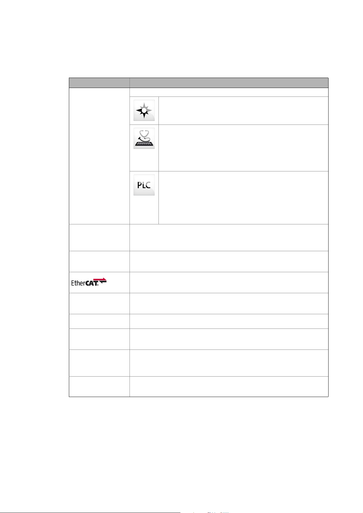
Term Meaning
Engineering Tools Software solutions for simple engineering at all stages
»EASY Navigator« – Ensures easy operator guidance
• All practical Lenze engineering tools at a glance
• Tools can be selected quickly
• Clearly arranged, simplifying the engineering process from the start
»EASY Starter« – Simple tool for service technicians
• Especially developed for the commissioning and maintenance of Lenze
devices
• Graphical user interface with few buttons
• Simple online diagnostics, parameterisation and commissioning
• No risk of accidentally changing the application
• Ready applications can be loaded to the device
»PLC Designer« – for process programming
• Creation of individual programs
• Programming of Logic & Motion in accordance with IEC 61131-3 (IL, LAD,
FBD, ST, SFC, and CFC editor), is based on CoDeSys V3
• Certified function blocks according to PLCopen Part 1 + 2
• Graphical DIN 66025 editor (G-code) with DXF import
• Integrated visualisation for an easy process representation
• All important pieces of information at a glance during commissioning
Lenze Controller The Lenze Controller (abbreviated: "Controller") is the central component of the
automation system which (by means of the runtime software) controls the Logic and
Motion functionalities.
The Lenze Controller communicates with the field devices via the fieldbus.
Engineering PC Use the Engineering PC and the engineering tools installed to configure and
parameterise the system.
The Engineering PC communicates with the Lenze Controller via Ethernet.
EtherCAT® is a real-time capable Ethernet system with top performance.
EtherCAT® is a registered trademark and patented technology licensed by Beckhoff
Automation GmbH, Germany.
HIPERFACE® HIPERFACE® stands for High Performance Interface and is a universal interface between
motor feedback system and inverter.
HIPERFACE® is a registered trademark of the SICK STEGMANN GmbH.
Object "Container" for one or several parameters which can be used to parameterise or monitor
the i700 servo inverter.
Index For the purpose of addressing, each object is provided with a unique index.
In this documentation the index is represented as a hexadecimal value and is identified
by a prefixed "0x", e.g. "0x1000".
Subindex If an object contains several parameters, the individual parameters are stored under
"subindexes".
In this documentation the colon is used as a separator between the index and the
subindex, e.g. "0x1018:1".
Touch probe A "Touch probe" is an event which can for instance be actuated in an edge-controlled
manner via a digital input to detect an actual value (that changes quickly) at the time of
activation and to process it further within the program afterwards.

Lenze · i700 servo inverter · Reference manual · DMS 1.5 EN · 03/2014 · TD05 15
1 About this documentation
1.3 Definition of notes used
_ _ _ _ _ _ _ _ _ _ _ _ _ _ _ _ _ _ _ _ _ _ _ _ _ _ _ _ _ _ _ _ _ _ _ _ _ _ _ _ _ _ _ _ _ _ _ _ _ _ _ _ _ _ _ _ _ _ _ _ _ _ _ _
1.3 Definition of notes used
The following signal words and symbols are used in this documentation to indicate dangers and
important information:
Safety instructions
Layout of the safety instructions:
Application notes
Danger!
(characterises the type and severity of danger)
Note
(describes the danger and gives information about how to prevent dangerous
situations)
Pictograph Signal word Meaning
Danger! Danger of personal injury through dangerous electrical voltage
Reference to an imminent danger that may result in death or serious personal
injury if the corresponding measures are not taken.
Danger! Danger of personal injury through a general source of danger
Reference to an imminent danger that may result in death or serious personal
injury if the corresponding measures are not taken.
Stop! Danger of property damage
Reference to a possible danger that may result in property damage if the
corresponding measures are not taken.
Pictograph Signal word Meaning
Note! Important note to ensure trouble-free operation
Tip! Useful tip for simple handling
Reference to another document
1 About this documentation
1.4 Structure of the parameter descriptions
16
Lenze · i700 servo inverter · Reference manual · DMS 1.5 EN · 03/2014 · TD05
_ _ _ _ _ _ _ _ _ _ _ _ _ _ _ _ _ _ _ _ _ _ _ _ _ _ _ _ _ _ _ _ _ _ _ _ _ _ _ _ _ _ _ _ _ _ _ _ _ _ _ _ _ _ _ _ _ _ _ _ _ _ _ _
1.4 Structure of the parameter descriptions
All parameters which you can use to parameterise or monitor the i700 servo inverter are stored
within "objects".
• For the purpose of addressing, each object is provided with a unique index. In this
documentation the index is represented as a hexadecimal value and is identified by a prefixed
"0x", e.g. "0x1000".
• If an object contains several parameters, they are stored in "subindexes". In this documentation
the colon is used as a separator between the index and the subindex, e.g. "0x1018:1".
Each parameter description is structured according to the following pattern:
Note!
This documentation is valid for the i700 servo inverter in the single axis version (single
inverter) and also as double axis (double inverter).
For parameters referring to one axis, both indexes (for axis A and axis B) are listed in the
parameter description. For a single axis, only the first index is relevant in this case.
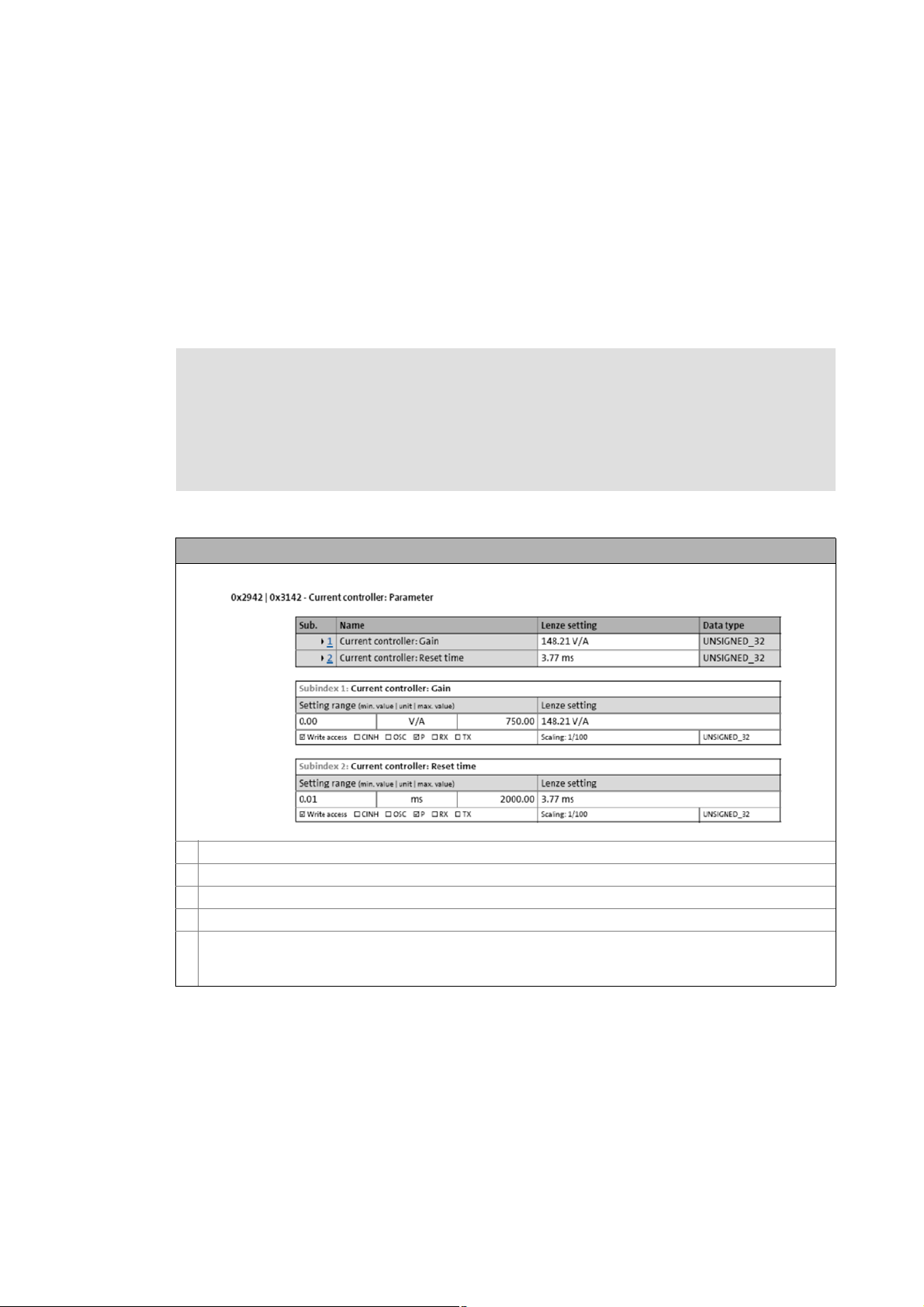
Example: Structure of the parameter descriptions in this documentation
Object index for axis A
Object index for axis B (only relevant for double axis)
Parameter or object name
If the object contains several parameters: Overview table with list of all subindexes
Table with detailed information about the corresponding parameter:
• Explanations & references (optional)
• Display options/possible settings, Lenze setting, attributes (for the meaning see the following table)

Lenze · i700 servo inverter · Reference manual · DMS 1.5 EN · 03/2014 · TD05 17
1 About this documentation
1.4 Structure of the parameter descriptions
_ _ _ _ _ _ _ _ _ _ _ _ _ _ _ _ _ _ _ _ _ _ _ _ _ _ _ _ _ _ _ _ _ _ _ _ _ _ _ _ _ _ _ _ _ _ _ _ _ _ _ _ _ _ _ _ _ _ _ _ _ _ _ _
Parameter attributes
Tip!
To find a specific object or parameter in this documentation, you can use the following
navigation helps:
• At the beginning of each main chapter, all objects which are described in the respective
chapter are listed in a table.
•In the Table of attributes
and the Index, all objects/parameters are listed with a
reference to the detailed description.
Name Meaning
Write access = Parameter can be written to.
= Parameter can only be read.
CINH = Parameter can only be written to if controller inhibit is set.
OSC = Parameter can be recorded by means of the oscilloscope function.
P = Parameter can be persisted.
Tx = Parameter can be mapped into the TPDO.
Rx = Parameter can be mapped into the RPDO.
Data type Data type of the parameter:
INTEGER_8 1 byte, with sign
INTEGER_16 2 bytes with sign
INTEGER_32 4 bytes with sign
UNSIGNED_8 1 byte without sign
UNSIGNED_16 2 bytes without sign
UNSIGNED_32 4 bytes without sign
UNSIGNED_64 8 bytes without sign
STRING(xx) ASCII string (with character length xx)
ARRAY [] OF... ARRAY
Scaling Scaling of the parameter

2 Parameter handling
2.1 Parameter transfer during initialisation
18
Lenze · i700 servo inverter · Reference manual · DMS 1.5 EN · 03/2014 · TD05
_ _ _ _ _ _ _ _ _ _ _ _ _ _ _ _ _ _ _ _ _ _ _ _ _ _ _ _ _ _ _ _ _ _ _ _ _ _ _ _ _ _ _ _ _ _ _ _ _ _ _ _ _ _ _ _ _ _ _ _ _ _ _ _
2 Parameter handling
2.1 Parameter transfer during initialisation
During the acceleration of the system, the controller and the controllers exchange configuration
data (e.g. bus cycle and PDO mapping). With regard to this, observe the following particular features
for the i700 servo inverter:
Parameter download
The i700 servo inverter itself does not
store parameter settings safe against mains failure. All
settings deviating from the i700 servo inverter "Lenze setting" (default) are maintained centrally in
the controller and are stored there permanently (persistently). During the initialisation at run-up,
only these deviations are transferred to the i700 servo inverter by the controller. Like this it is
ensured that the i700 servo inverter works with the parameter settings provided for it.
Firmware download (optional)
If required, the firmware of the i700 servo inverter can be stored together with the »PLC Designer«
project. During the run-up, the controller then checks whether the firmware version in the i700
servo inverter complies with the firmware version stored in the project for this device. If this is not
the case, the controller loads the firmware version stored in the project to the i700 servo inverter.
Like this, it can be ensured for "Device replacement" service work that the replacement device also
works with the same firmware version as the original device.

Lenze · i700 servo inverter · Reference manual · DMS 1.5 EN · 03/2014 · TD05 19
2 Parameter handling
2.2 Storage parameter set (par001.*) and total parameter set (par000.*)
_ _ _ _ _ _ _ _ _ _ _ _ _ _ _ _ _ _ _ _ _ _ _ _ _ _ _ _ _ _ _ _ _ _ _ _ _ _ _ _ _ _ _ _ _ _ _ _ _ _ _ _ _ _ _ _ _ _ _ _ _ _ _ _
2.2 Storage parameter set (par001.*) and total parameter set (par000.*)
For the storage of the i700 servo inverter parameters, two different parameter sets are provided,
which are stored in different parameter set files in the higher-level controller:
Storage parameter set (par001.i7psf)
• Only contains the parameters of the i700 servo inverter which are writable and identified with
the "P" attribute (persistent).
• Parameters can be read out from the i700 servo inverter and saved to the file. Conversely, the
parameters stored can be written to the i700 servo inverter again.
• Recommended for storage and archiving of the controllers settings.
Total parameter set (par000.i7psf)
• Contains all parameters of the i700 servo inverter, including the mere display parameters which
vary permanently during operation.
• The total parameter set can only be read from the i700 servo inverter.
• Use for purposes of service and diagnostics.
The structure of the parameter set file is described in the appendix.
Structure of the parameter set file ( 310)

2 Parameter handling
2.2 Storage parameter set (par001.*) and total parameter set (par000.*)
20
Lenze · i700 servo inverter · Reference manual · DMS 1.5 EN · 03/2014 · TD05
_ _ _ _ _ _ _ _ _ _ _ _ _ _ _ _ _ _ _ _ _ _ _ _ _ _ _ _ _ _ _ _ _ _ _ _ _ _ _ _ _ _ _ _ _ _ _ _ _ _ _ _ _ _ _ _ _ _ _ _ _ _ _ _
2.2.1 Saving a parameter set from the i700 to a file (export)
Reading out and storing the parameters from the i700 servo inverter is initiated and controlled from
the higher-level controller. For reading out a parameter set, the corresponding parameter values are
summarised in a parameter set file (par001.* or par000.*) in the i700 servo inverter and are then
transferred as a file to the controller via EtherCAT.
2.2.2 Loading the stored parameter set to the i700 (import)
Loading a stored parameter set file to the i700 servo inverter is initiated and controlled from the
higher-level controller, just like in the case of the read-out. The storage parameter set file is
transferred to the i700 servo inverter as a file via EtherCAT, and the parameter settings are loaded
(imported).
For logical reasons, it is only possible to transfer "storage parameter set files" (par001.*) to the i700
servo inverter. Display parameters are updated under normal operating conditions and do not need
to be loaded.
2.2.3 Monitoring of the parameter import (error report)
When the parameter import has been completed, the "parErr.i7psf" error report file is created. This
file is recreated automatically during every import.
On the basis of the error report it can be determined whether errors have occurred during the
parameter import:
• Parameters that have been transferred with errors are listed there together with their index,
subindex, and error code (SDO abort code).
• If no errors have occurred, this data area of the file is blank. However, the headers including the
checksum are available and valid nevertheless.
Note!
In the case of Lenze controllers, the parameter set files are transferred as "files" via GCI
("Generic Communication Interface").
• GCI is a Lenze-specific application protocol which uses CoE ("CANopen over
EtherCAT").
• Other control manufacturers may also use FoE ("File Access over EtherCAT") for the
transfer.

Lenze · i700 servo inverter · Reference manual · DMS 1.5 EN · 03/2014 · TD05 21
2 Parameter handling
2.3 Cyclic redundancy check (CRC) - parameter set comparison on the basis of the checksum
_ _ _ _ _ _ _ _ _ _ _ _ _ _ _ _ _ _ _ _ _ _ _ _ _ _ _ _ _ _ _ _ _ _ _ _ _ _ _ _ _ _ _ _ _ _ _ _ _ _ _ _ _ _ _ _ _ _ _ _ _ _ _ _
2.3 Cyclic redundancy check (CRC) - parameter set comparison on the basis of the checksum
Each parameter set features an individual checksum (CRC32), which is composed of the settings of
all storable indexes (P-flag) of the parameter set. When a setting changes, there is also a change in
the checksum.
Cyclic redundancy check (CRC):
By comparison of the checksums of parameter sets it can be determined very quickly whether
parameter sets are identical or not. In particular, it is thus determined for the i700 servo inverter
whether the parameter set stored in the controller is identical to that in the i700 servo inverter and
therefore does not have to be loaded again.
0x2030 - Parameter set: Validity check (CRC)
Checksum for quick comparison of the storage parameter set (par001.i7psf)
• If the checksum shown here is identical to the checksum of the parameter set file stored in the Lenze Controller,
it is not necessary to write the parameter set file to the i700 servo inverter.
• If the checksums are different, however, there are deviations between the parameter set available in the Lenze
Controller and that in the i700 servo inverter.
• The checksum cannot be used for comparison of the total parameter set (par000.i7psf).
Display area (min. value | unit | max. value) Initialisation
0 4294967295
Write access CINH OSC P RX TX UNSIGNED_32
3 Communication with the controller
3.1 Acceleration of the system (initialisation)
22
Lenze · i700 servo inverter · Reference manual · DMS 1.5 EN · 03/2014 · TD05
_ _ _ _ _ _ _ _ _ _ _ _ _ _ _ _ _ _ _ _ _ _ _ _ _ _ _ _ _ _ _ _ _ _ _ _ _ _ _ _ _ _ _ _ _ _ _ _ _ _ _ _ _ _ _ _ _ _ _ _ _ _ _ _
3 Communication with the controller
Objects described in this chapter
Tip!
The communication objects important for the integration of the controller with external
control are described in the appendix.
Communication objects
( 313)
3.1 Acceleration of the system (initialisation)
To establish communication, the i700 servo inverter must be supplied with voltage. During the
acceleration of the system, the controller and the drive exchange configuration data.
The controller transmits the following configuration data to the i700 servo inverter:
•Bus cycle
• This is the basic cycle within which the EtherCAT bus is actuated. The bus cycle is given as a
multiple of 125 μs.
• The bus cycle equals the communication cycle within which the process data are exchanged
cyclically. New process data are only accepted and generated in the Servo-Inverter i700
maximally every 250 μs.
• Parameter set determined during commissioning.
• Among other things, it includes information about feedforward control values, the mains
voltage and the switching frequency as well as controller parameters adapted to the motor
module which are used for the motor control.
• Configuration of the process data transmitted cyclically via EtherCAT (PDO mapping)
"EtherCAT control technology" communication manual
Here you will find detailed information on the EtherCAT configuration and
commissioning of Lenze devices in the EtherCAT network.
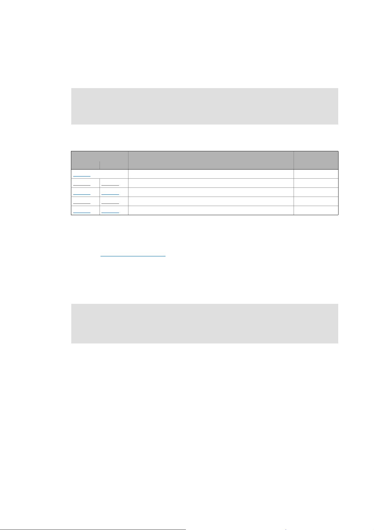
Object Name Data type
Axis A Axis B
0x2020 EoE information RECORD
0x2824
0x3024 Device control via PDO: Activation UNSIGNED_8
0x2830
0x3030 Lenze control word UNSIGNED_16
0x2831
0x3031 Lenze status word UNSIGNED_16
0x2833
0x3033 Lenze statusword 2 UNSIGNED_16
Stop!
Before switching on the i700 servo inverter for the first time, check the entire wiring with
regard to completeness, short circuit, and earth fault.

Lenze · i700 servo inverter · Reference manual · DMS 1.5 EN · 03/2014 · TD05 23
3 Communication with the controller
3.1 Acceleration of the system (initialisation)
_ _ _ _ _ _ _ _ _ _ _ _ _ _ _ _ _ _ _ _ _ _ _ _ _ _ _ _ _ _ _ _ _ _ _ _ _ _ _ _ _ _ _ _ _ _ _ _ _ _ _ _ _ _ _ _ _ _ _ _ _ _ _ _
Note!
If no data for the initialisation of the controller are transmitted, the i700 servo inverter
uses the "Lenze setting" for the parameters.
Power up/Power down
In the case of "Power up" and "Power down", no undefined states can occur that cause
damage to the device or motor movements which are not requested or not braked.
In the case of a voltage failure/dip, there is no immediate response by the i700 servo
inverter. The functionality is to be maintained for as long as possible.
24-V supply voltage monitoring
( 235)
Persistent data storage
A complete, persistent storage of the drive configuration which remains the same even
though the controller is switched off from time to time is carried out in the higher-level
controller instead of in the i700 servo inverter. Hence, the controller needs to transmit
the configuration data again to the i700 servo inverter after a power up.
However, in the case of a power down, the following device data are stored persistently
in the i700 servo inverter:
• Power-on and elapsed-hour meter (0x2D81
or 0x3581 for axis B)
• History buffer
( 265)

3 Communication with the controller
3.2 Process data (cyclic PDO transfer) and PDO mapping
24
Lenze · i700 servo inverter · Reference manual · DMS 1.5 EN · 03/2014 · TD05
_ _ _ _ _ _ _ _ _ _ _ _ _ _ _ _ _ _ _ _ _ _ _ _ _ _ _ _ _ _ _ _ _ _ _ _ _ _ _ _ _ _ _ _ _ _ _ _ _ _ _ _ _ _ _ _ _ _ _ _ _ _ _ _
3.2 Process data (cyclic PDO transfer) and PDO mapping
Cyclic process data are transferred cyclically between the controller (master) and the controllers
(slaves) as so-called Process Data Objects (PDOs).
• The i700 servo inverter supports the following bus cycle times of the EtherCAT:
0.125 ms*
0.250 ms
0.500 ms
1.000 ms
... (only integer multiple of 1 ms)
10.000 ms (max. cycle time)
* Note: With a bus cycle time of 0.125 ms, the process data is updated only every 0.250 ms, as
this is the fastest control cycle for the setpoint and actual value transfer.
• The processing time of a process date through the drive is t=max[bus cycle, 0.250 ms]. If the
entire chain from the control via the drive back to the control is considered, a process data needs
2 bus cycles in addition (for Lenze C3200) . Thus, the turnaround time for a PDO can be indicated
with 3 bus cycles.
• For the process data communication, the i700 servo inverter supports the mapping of max. 32
process data objects (PDOs) with a total max. size of 100 bytes per direction of transmission.
• A fixed PDO mapping preconfigured by Lenze is available for every CiA402 operating mode
supported by the i700 servo inverter. Every PDO mapping includes of several objects from the
Object directory
.
• For every axis, further fixed, preconfigured PDO mappings can be used for touch probe
functionality.
• In addition to the fixed, preconfigured PDO mappings, freely configurable PDO mappings are
available for every axis which can be used for individual PDO mapping. A maximum of 8 objects
from the Object directory
can be configured per direction of transmission.
• The configuration of the PDOs actually transmitted between the controller and the i700 servo
inverter is carried out via the »PLC Designer«.
• Experience shows that most i700 servo inverters are operated in one of the available CiA402
operating modes (csp, csv, cst or vl). We therefore recommend to use and activate the fixed
PDO mapping preconfigured by Lenze for the selected operating mode. In doing so all
parameters that usually need to be replaced during a cyclic PDO transfer can be accessed.
• If you wish to use touch probe functionality in addition, optionally and additionally activate
the fixed, preconfigured PDO mapping for touch probe functionality.
• Moreover, the PDO mappings that can be freely configured by the user can be optionally
activated. However, we recommend to use these freely configurable PDO mappings in special
cases only, if no standard PDO mapping is suitable for the case of application at hand. Special
thought should be given to the aspect of traceability in case of service.
"EtherCAT control technology" communication manual
Here you will find some detailed information on the configuration of the process data
objects (PDO mapping) with the »PLC Designer«.
Lenze · i700 servo inverter · Reference manual · DMS 1.5 EN · 03/2014 · TD05 25
3 Communication with the controller
3.2 Process data (cyclic PDO transfer) and PDO mapping
_ _ _ _ _ _ _ _ _ _ _ _ _ _ _ _ _ _ _ _ _ _ _ _ _ _ _ _ _ _ _ _ _ _ _ _ _ _ _ _ _ _ _ _ _ _ _ _ _ _ _ _ _ _ _ _ _ _ _ _ _ _ _ _
3.2.1 Synchronisation with "Distributed clocks" (DC)
The "Distributed clocks" (DC) function enables an exact time adjustment for applications where
several auxiliary axes carry out a coordinated movement at the same time. The data is accepted
synchronously with the PLC program. In the case of the DC synchronisation, all slaves are
synchronised with a reference clock, called the "DC master".
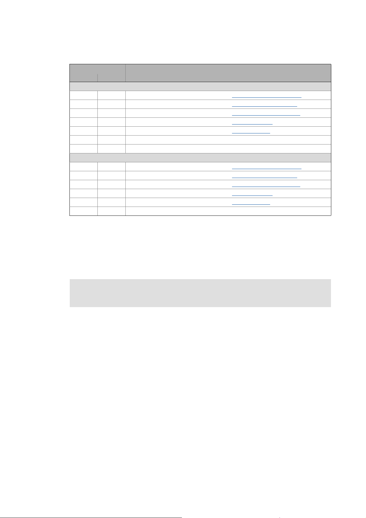
Object Info
Axis A Axis B
RPDO mapping – configuration of the process data (setpoints) from the controller to the i700 servo inverter
0x1600 0x1610 Fixed, preconfigured PDO mapping object for "Cyclic sync position mode (csp)
"
0x1601 0x1611 Fixed, preconfigured PDO mapping object for "Cyclic sync torque mode (cst)
"
0x1602 0x1612 Fixed, preconfigured PDO mapping object for "Cyclic sync velocity mode (csv)
"
0x1603 0x1613 Fixed, preconfigured PDO mapping object for "Velocity mode (vl)
"
0x1604 0x1614 Fixed, preconfigured PDO mapping object for "Touch probe (TP)
"
0x1605 0x1615 Freely configurable PDO mapping object
0x1606 0x1616 Fixed, preconfigured PDO mapping object for torque limit values
TPDO mapping – configuration of process data (actual values) from the i700 servo inverter to the controller
0x1A00 0x1A10 Fixed, preconfigured PDO mapping object for "Cyclic sync position mode (csp)
"
0x1A01 0x1A11 Fixed, preconfigured PDO mapping object for "Cyclic sync torque mode (cst)
"
0x1A02 0x1A12 Fixed, preconfigured PDO mapping object for "Cyclic sync velocity mode (csv)
"
0x1A03 0x1A13 Fixed, preconfigured PDO mapping object for "Velocity mode (vl)
"
0x1A04 0x1A14 Fixed, preconfigured PDO mapping object for "Touch probe (TP)
"
0x1A05 0x1A15 Freely configurable PDO mapping object
"EtherCAT control technology" communication manual
Here you will find some detailed information about DC synchronisation.

3 Communication with the controller
3.3 Parameter data transfer (SDO communication)
26
Lenze · i700 servo inverter · Reference manual · DMS 1.5 EN · 03/2014 · TD05
_ _ _ _ _ _ _ _ _ _ _ _ _ _ _ _ _ _ _ _ _ _ _ _ _ _ _ _ _ _ _ _ _ _ _ _ _ _ _ _ _ _ _ _ _ _ _ _ _ _ _ _ _ _ _ _ _ _ _ _ _ _ _ _
3.3 Parameter data transfer (SDO communication)
In addition to the cyclic process data transfer, parameter data can be transferred as so-called SDOs
(Service Data Objects) in a non-cyclic manner within an individual datagram between the controller
(master) and the controllers (slaves).
• SDO communication is implemented according to the EtherCAT-CoE protocol, using a mailbox.
• SDO communication enables read or write access to all indices contained in the object directory
of the i700 servo inverter.
• The turnaround time for an SDO (request by the control, transport via the bus, processing in the
drive, transport of the response back to the control) is between 1ms and 100ms plus 2*bus
cycle time (typically 10 ms).
3.3.1 Object directory
The object directory contains the specific indices for all axes. The object directory is structured
according to specifications of the EtherCAT Technology Group (ETG):
Range Index area
Device Axis A Axis B
Communication Area 0x1000 - 0x1FFF
Identification data 0x1000 - 0x1018 - -
Sync manager 0x1C00 - 0x1C33 - -
PDO mapping - 0x1600 - 0x1606
0x1A00 - 0x1A05
0x1610 - 0x1616
0x1A10 - 0x1A15
Manufacturer specific area 0x2000 - 0x5FFF
Device settings 0x2000 - 0x27FF - -
Axis identification - 0x2800 - 0x281F 0x3000 - 0x301F
Axis control - 0x2820 - 0x283F 0x3020 - 0x303F
Error management - 0x2840 - 0x28FF 0x3040 - 0x30FF
Motor control & motor settings - 0x2900 - 0x2CFF 0x3100 - 0x34FF
Touch probe - 0x2D00 - 0x2D3F 0x3500 - 0x353F
Monitoring functions - 0x2D40 - 0x2D7F 0x3540 - 0x357F
Diagnostics - 0x2D80 - 0x2DBF 0x3580 - 0x35BF
Service/internal - 0x2DC0 - 0x2E3F 0x35C0 - 0x363F
Reserved - 0x2E40 - 0x2FFF 0x3640 - 0x37FF
CiA402 profile specific area 0x6000 - 0xDFFF
Device profile CiA402 - 0x6000 - 0x67FF 0x6800 - 0x6FFF

Lenze · i700 servo inverter · Reference manual · DMS 1.5 EN · 03/2014 · TD05 27
3 Communication with the controller
3.3 Parameter data transfer (SDO communication)
_ _ _ _ _ _ _ _ _ _ _ _ _ _ _ _ _ _ _ _ _ _ _ _ _ _ _ _ _ _ _ _ _ _ _ _ _ _ _ _ _ _ _ _ _ _ _ _ _ _ _ _ _ _ _ _ _ _ _ _ _ _ _ _
3.3.2 SDO abort codes
If an SDO request is evaluated negatively, a corresponding abort code is output:
3.3.3 ESI: EtherCAT Slave Information file (device description)
The EtherCAT Slave Information file (EtherCAT Device Description file) contains all information
about the device (operating modes, parameters, …).
• The EtherCAT Slave Information file is integrated by the EtherCAT network configuration tool in
order to be able to configure and commission the devices.
• Part of the information contained in the EtherCAT Slave Information file can be uploaded online
by the EtherCAT master by accessing the EtherCAT EEPROM of the device. The description of the
object directory can also be identified online.
SDO abort code Description
0x0000 0000 No error
0x0503 0000 The status of the toggle bit has not changed.
0x0504 0000 SDO protocol time-out
0x0504 0005 The space in the main memory is not sufficient.
0x0601 0000 Access to object not supported.
0x0601 0001 Read access to a write-protected object.
0x0601 0002 Write access to a write-protected object.
0x0602 0000 Object is not listed in the object directory.
0x0604 0041 Object cannot be mapped into the PDO.
0x0604 0042 The number and/or length of the mapped objects would exceed the PDO length.
0x0604 0043 General parameter incompatibility
0x0604 0047 General internal device incompatibility
0x0606 0000 Access has failed because of hardware errors.
0x0607 0010 Wrong data type or parameter length.
0x0607 0012 Wrong data type (parameter length is too large).
0x0607 0013 Wrong data type (parameter length is too small).
0x0609 0011 Subindex does not exist.
0x0609 0030 The value range for parameters is too large (only for write access).
0x0609 0031 The parameter value is too high.
0x0609 0032 The parameter value is too low.
0x0800 0000 General error
0x0800 0020 Data cannot be transferred or saved to the application.
0x0800 0021 Data cannot be transferred or saved to the application because of local control.
0x0800 0022 Data cannot be transferred/saved to the application because of current device state.
3 Communication with the controller
3.4 Activating the control via PDO
28
Lenze · i700 servo inverter · Reference manual · DMS 1.5 EN · 03/2014 · TD05
_ _ _ _ _ _ _ _ _ _ _ _ _ _ _ _ _ _ _ _ _ _ _ _ _ _ _ _ _ _ _ _ _ _ _ _ _ _ _ _ _ _ _ _ _ _ _ _ _ _ _ _ _ _ _ _ _ _ _ _ _ _ _ _
3.4 Activating the control via PDO
0x2824 | 0x3024 - Device control via PDO: Activation
3.5 Lenze control and status word
0x2830 | 0x3030 - Lenze control word
This object serves to switch off all RPDOs (from the device's point of view) so that the device is exclusively controlled
via SDOs.
• This is, for instance, required for manual enable of commissioning functions and test modes via the (0x6040
control word 0x6840
for axis B). Enable/inhibit via control word
Selection list (Lenze setting printed in bold)
0Off
1Activate
Write access CINH OSC P RX TX UNSIGNED_8
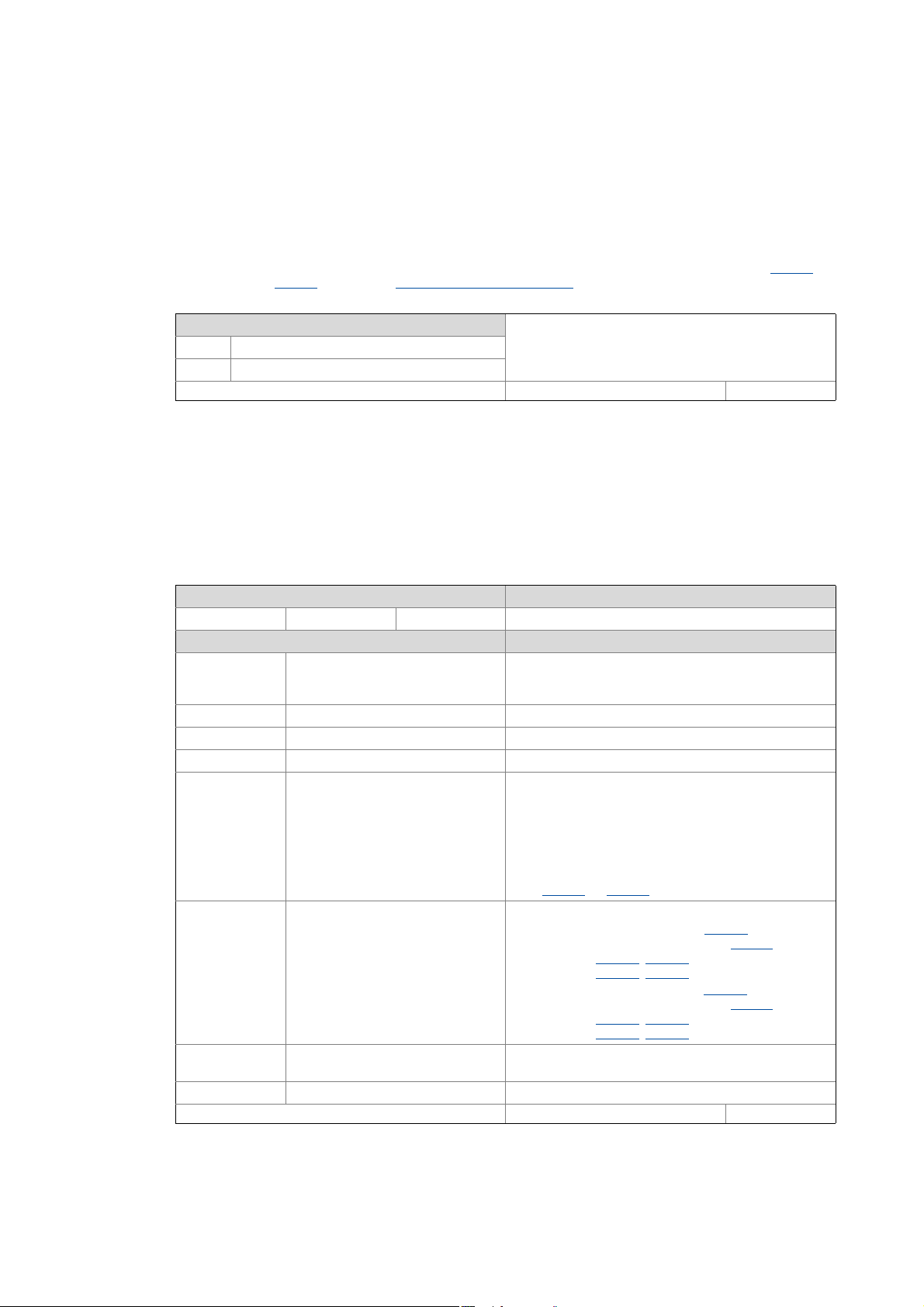
Via the Lenze control word, the control functions can be influenced.
Setting range (min. value | unit | max. value) Lenze setting
0x0000 0xFFFF 0x0000
Value is bit-coded: ( =bit set) Info
Bit 0 Flying restart: Completed Via this bit, the control reports the acceptance of the
speed found to the "Flying restart" function. The flying
restart process is now completed.
Bit 1 Flying restart: Blocked "1" ≡ Block flying restart process
Bit 2 Reserved
Bit 3 Reserved
Bit 4 Speed controller: Load I component "1" ≡ Set starting value of the torque
• In case of servo control, this corresponds to the I
component of the speed controller, in case of V/f
operation to the modulation of the slip
compensation.
• As long as this bit is set to "1", the I component and
the slip compensation are set to the starting value set
in 0x2902
(or 0x3102 for axis B).
Bit 5 Position: Traverse to new actual
position
"1" ≡ Set/relatively shift actual position
• Axis A: Set the actual position (0x6064
) under
consideration of the set resolution (0x608F
) to the
value set in 0x2983
(0x2984 = 0), or shift it by the
value set in 0x2983
(0x2984 = 1).
• Axis B: Set the actual position (0x6864
) under
consideration of the set resolution (0x688F
) to the
value set in 0x3183
(0x3184 = 0), or shift it by the
value set in 0x3183
(0x3184 = 1).
Bit 6 Activate DC-injection braking or
short-circuit braking
"1" ≡ Trigger DC-injection braking for asynchronous
motor or short-circuit braking for synchronous motor
Bits 7-15 Reserved
Write access CINH OSC P RX TX UNSIGNED_16
Lenze · i700 servo inverter · Reference manual · DMS 1.5 EN · 03/2014 · TD05 29
3 Communication with the controller
3.5 Lenze control and status word
_ _ _ _ _ _ _ _ _ _ _ _ _ _ _ _ _ _ _ _ _ _ _ _ _ _ _ _ _ _ _ _ _ _ _ _ _ _ _ _ _ _ _ _ _ _ _ _ _ _ _ _ _ _ _ _ _ _ _ _ _ _ _ _
0x2831 | 0x3031 - Lenze status word
In the Lenze status word, messages are combined that go beyond the CiA specification.
Display area (min. value | unit | max. value) Initialisation
0x0000 0xFFFF
Value is bit-coded: Info
Bit 0 Position controller: In limitation Position mode: Output of the position controller in
limitation
Bit 1 Speed: Limited speed setpoint 1 Input of speed controller 1 in limitation
Bit 2 Speed controller: In limitation Output of speed controller 1 in limitation
Bit 3 Torque: Limited target torque Target torque in limitation
Bit 4 Motor: Limited current setpoint Setpoint current in limitation
Bit 5 Speed: Limited speed setpoint 2 Torque mode: Input of speed controller 2 in limitation
Bit 6 Upper speed limit is active Torque mode: Speed is limited to the upper speed limit
(0x2946:1
or 0x3146:1 for axis B)
Bit 7 Lower speed limit is active Torque mode: Speed is limited to the lower speed limit
(0x2946:2
or 0x3146:2 for axis B)
Bit 8 Flying restart in progress ... V/f operation: "Flying restart process" function is active
Bit 9 Flying restart: Ready for operation V/f operation: "Flying restart process" function has
acquired speed
Bit 10 Limited output frequency V/f operation: Setpoint frequency in limitation
Bit 11 Asynchronous motor magnetised In case of servo control for synchronous motor (SM):
• Bit is always set.
In case of servo control for asynchronous motor (ASM):
• Bit is set if the difference between setpoint and actual
flux is smaller than 10 % of setpoint flux.
• Bit is reset if the difference has increased to 15 % of
setpoint flux.
In case of V/f operation:
• Bit is set if the rotor time constant has been passed
seven times, calculated from the time the controller
has been enabled and no restart on the fly has been
active and the total motor current has reached 20 %
of the rated motor current for the first time.
Otherwise 0.
Bit 12 Motor phase failure detection in
progress ...
Motor phase failure detection is active
Bit 13 Feedback: Open circuit Position feedback is interrupted
Bit 14 Delay time: 'Reset error' is active The error cannot be reset before the delay time has
expired. The remaining delay time is displayed in 0x2840
(or 0x3040
for axis B).
Bit 15 Clamp is active V/f operation: Clamp (short-time inhibit of the inverter)
is active
Write access CINH OSC P RX TX UNSIGNED_16
3 Communication with the controller
3.5 Lenze control and status word
30
Lenze · i700 servo inverter · Reference manual · DMS 1.5 EN · 03/2014 · TD05
_ _ _ _ _ _ _ _ _ _ _ _ _ _ _ _ _ _ _ _ _ _ _ _ _ _ _ _ _ _ _ _ _ _ _ _ _ _ _ _ _ _ _ _ _ _ _ _ _ _ _ _ _ _ _ _ _ _ _ _ _ _ _ _
0x2833 | 0x3033 - Lenze statusword 2
From version 01.03
Display area (min. value | unit | max. value) Initialisation
0x0000 0xFFFF
Value is bit-coded: Info
Bit 0 Feedback modification Changes in the settings of the feedback system have
been executed. The status bit is reset at controller
enable.
Bit 1 Manual test mode active A manual test mode is active
(0x2825
or 0x3025 = 1, 2 or 3)
Bit 2 Manual control mode active Manual control mode is active
(0x2825
or 0x3025 = 4)
Bit 3 Angle tracking control: Active Reserved
Bit 4 Absolute value encoder selected From version 01.06
Absolute feedback system selected (parameterised)
• In case of the "resolver" device variant, this bit is set if
the resolver pole pair number "1" is set in 0x2C43
(or
0x3443
for axis B).
• In case of the "enco der" devi ce variant, thi s bit is se t if
the encoder type "2: Hiperface absolute value
encoder" is set in 0x2C40
(or 0x3440 for axis B).
Bit 5 Absolut position available From version 01.06
Initialisation of the selected feedback system is
completed. All information of the feedback system have
been transmitted.
• In case of an error in the feedback system, this bit is
set to "0" as long as the error exists.
Bit 6 DC-injection braking or short-circuit
braking: Active
From version 01.06
DC-injection braking for asynchronous motor or short-
circuit braking for synchronous motor is active
Bit 7-15 Reserved
Write access CINH OSC P RX TX UNSIGNED_16
Loading...