

MA_p500
.MVY
L-force Controls
Montageanleitung
Mounting Instructions
Instructions de montage
Instrucciones para el montaje
Istruzioni per il montaggio
Controller-based Automation
Ä.MVYä
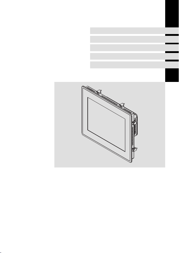
Controller p500
Panel Controller

Approval
Underwriter Laboratories (UL), UL508 and CSA C22.2 No. 142-M1987, (UL File Number
E236341)
Ratings
ƒ Input24VDC,max.1.7A
ƒ Max. Surrounding temperature:
– P500 7: 55 °C, in vertical (landscape or portrait) mounting position only at relative
humidity of 60%rh with a linear derating to 30°C at 90%rh.
– P500 10,4: 55°C in vertical (landscape or portrait)mounting position only at a
relative humidity of 55%rh with a linear derating to 40°C at 90%rh.
– P500 15,0: 55°C in vertical (landscape or portrait)mounting position only at a
relative humidity of 45%rh with a linear derating to 40°C at 90%rh.
ƒ These devices are intended for mounting in the outer surface of an enclosure, Type 1,
4 and 4X indoor use only.
Warnings!
Field Wiring Markings
Wiring Terminal MSTB 2,5/3-STF-5,08:
ƒ Use 60° or 60/75° C copper wire only.
ƒ AWG 18 ... AWG 12 (0.82 mm
ƒ Torque 5...7 lb-in (0.5 ... 0.6 Nm)
Device
ƒ For use in a pollution degree 2 and controlled environment only.
ƒ For use on a Flat Surface of a Type 1, 4 and 4x Indoor Use Only Enclosure
Optional filed bus module
ƒ Use only together with appropriate cable connectors, provided with screws
for securement and secure connector to avoid loosening.
2
... 3.3 mm2)
MA_p500 DE/EN/FR/ES/IT 2.0
2

Homologation
Underwriter Laboratories (UL), UL508 et CSA C22.2 n° 142-M1987, (n° de dossier UL
E236341)
Caractéristiques assignées
ƒ Entrée 24 V CC, maximum 1,7 A
ƒ Température ambiante maximale :
– P500 7 : 55 °C sur un axe vertical uniquement (montage horizontal ou vertical)
pour 60%rh d’humidité relative, réduction linéaire à 30°C à 90%rh d’humidité.
– P500 10,4: 55 °C sur un axe vertical uniquement (montage horizontal ou vertical)
pour 55%rh d’humidité relative, réduction linéaire à 40°C à 90%rh d’humidité.
– P500 15,0: 55°C sur un axe vertical uniquement (montage horizontal ou vertical)
pour 45%rh d’humidité relative, réduction linéaire à 40°C à 90%rh d’humidité.
ƒ Ces équipements sont destinés à être montés sur la surface extérieure d’un coffret de
protection de types 1, 4 et 4X (usage intérieur exclusivement).
Warnings!
Marquage du câblage à pied d’oeuvre
Bornier de câblage MSTB 2,5/3-STF-5,08 :
ƒ Utiliser exclusivement des conducteurs en cuivre 60 °C ou 60/75 °C.
ƒ AWG 18 ... AWG 12 (0.82 mm
ƒ Couplede5à7lb-in(0,5...0,6Nm)
Appareil
ƒ Destiné uniquement à un environnement contrôlé caractérisé par le degré
de pollution 2.
ƒ Conçu pour une utilisation sur une surface plane, coffret de type 1, 4 et 4x
(usage intérieur uniquement).
Module bus en option
ƒ A utiliser exclusivement avec des connecteurs de câble à vis adaptés. Fixer
les connecteurs pour éviter toute déconnexion.
2
... 3.3 mm2)
MA_p500 DE/EN/FR/ES/IT 2.0
3

Lesen Sie die Bedienungsanleitung zum Panel Controller p500, bevor Sie mit
den Arbeiten beginnen. Dort finden Sie weitere wichtige Informationen, z. B.:
ƒ Lieferumfang
ƒ Bestimmungsgemäße Verwendung
ƒ Identifikation der Geräte
ƒ Technische Daten
ƒ Elektrische Installation
ƒ Bedienung
ƒ Wartung
Dokumentationen und Hilfsmittel rund um die Lenze Produkte finden Sie im
Download-Bereich unter
http://www.Lenze.com
ƒ Montage/Demontage bei ausgeschalteter Versorgungsspannung durchführen, um
elektronische Bauteile vor Beschädigung zu schützen.
ƒ Der Montageort muss den in den Technischen Daten genannten Einsatzbedingungen
immer entsprechen. Ggf. zusätzliche Maßnahmen ergreifen.
ƒ Im Einbauraum ist eine ständige und ausreichende Luftzirkulation zwingend
erforderlich, um die Wärme des Geräts abzuleiten. Die Lüftungsschlitze dürfen nicht
abgedeckt werden.
ƒ Achten Sie bei der Wahl des Aufstellortes auf eine ergonomische Stellung des
Bildschirms, sowie auf Lichteinfall, der Reflektionen auf dem Bildschirm verursachen
könnte.
ƒ Während der Montage besteht die Gefahr, dass der Controller aus dem
Einbauausschnitt fällt. Sichern Sie ihn deshalb gegen Herunterfallen, bis alle
Schraubspanner montiert sind.
ƒ Während der Montage liegt der Dichtring des Frontrahmens frei und kann
beschädigt werden.
– Gehen Sie während der Montage sorgsam mit dem Dichtring um.
– Schützen Sie den Dichtring vor UV-Strahlen.
– Kontrollieren Sie den Dichtring jedes Mal auf Unversehrtheit, bevor Sie das Gerät
montieren.
ƒ Das Gerät muss fest im Einbauausschnitt sitzen und die Frontplattendichtung muss
korrekt aufliegen. Andernfalls wird auf der Gerätevorderseite die Schutzklasse IP65
nicht erreicht!
ƒ Der Kühlkörper auf der Rückseite des L-force Controllers wird während des Betriebs
sehr heiß. Es besteht Verbrennungsgefahr!
– Vor Arbeiten am Gerät dessen Kühlkörpertemperatur prüfen.
MA_p500 DE/EN/FR/ES/IT 2.0
4

Before starting work, read the operating instructions for the p500 panel
controller. These instructions provide additional important information such
as:
ƒ the scope of supply
ƒ application as directed
ƒ identification of the devices
ƒ technical data
ƒ electrical installation
ƒ operation
ƒ maintenance
Documentation and tools for Lenze products can be found in the download
section of our website at
http://www.Lenze.com
ƒ To prevent damage to electronic components, only mount/remove the device with
the voltage supply switched off.
ƒ The mounting location always must correspond to the operating conditions specified
in the technical data. If required, take additional measures.
ƒ Continuous and adequate air circulation is essential in the installation space so that
the device’s heat is correctly dissipated. Make sure that the ventilation slots are never
covered.
ƒ When choosing the installation location, ensure that the screen is in an
ergonomically suitable position and that light is unable to cause irritating reflections
on the screen.
ƒ During installation, there is a danger that the controller will fall out of the mounting
cutout. You should therefore secure it to prevent this happening until all screw
clamps have been fitted.
ƒ During mounting, the gasket of the front frame is exposed and can be damaged.
– Handle the gasket with care during mounting.
– Protect the gasket against ultraviolet rays.
– Checkthegaskettomakesureitisundamaged before you install the device.
ƒ The device must be securely seated in the mounting cutout and the front panel seal
must be correctly fitted. Otherwise, class of protection IP65 will not be achieved on
the front side of the device!
ƒ The heat sink on the rear of the L-force controller becomes very hot during operation.
There is therefore a risk of burns!
– Before working on the device, check the temperature of its heat sink.
MA_p500 DE/EN/FR/ES/IT 2.0
5

Veuillez lire attentivement les instructions de mise en service du contrôleur
Panel Controller p500 avant toute action. Vous y trouverez des informations
complémentaires importantes sur les points suivants :
ƒ Equipement livré
ƒ Utilisation conforme à la fonction
ƒ Identification des appareils
ƒ Spécifications techniques
ƒ Installation électrique
ƒ Commande
ƒ Maintenance
Vous trouverez des informations et des outils d’aide à la détermination des
produits Lenze sur Internet, dans la zone de téléchargements à l’adresse
suivante :
http://www.Lenze.com
ƒ Procéder au montage/démontage à l’état hors tension, afin d’éviter tout risque
d’endommagement des composants électroniques.
ƒ L’emplacement de montage doit impérativement remplir les conditions d’utilisation
décrites dans les spécifications techniques. Si nécessaire, prendre des mesures
complémentaires.
ƒ Assurer impérativement une ventilation suffisante permanente pour évacuer la
chaleur dissipée par l’appareil. Ne pas couvrir les orifices de ventilation.
ƒ Placer l’écran en fonction des exigences ergonomiques et de la lumière directe qui
risque de provoquer des réflexions sur l’écran.
ƒ Pendantlesopérationsdemontage,lecontrôleurrisquedetomberdel’encochede
montage. Le maintenir afin d’éviter qu’il tombe jusqu’à ce que tous les goujons
soient montés.
ƒ Pendant les opérations de montage, le joint d’étanchéité du cadre avant n’est pas
protégé et risque alors d’être endommagé.
– Pendant le montage, manipuler le joint d’étanchéité avec soin.
– Protéger le joint d’étanchéité contre les rayons UV.
– Avant chaque montage de l’appareil, vérifier l’intégrité du joint d’étanchéité.
ƒ L’appareil doit être bien fixé dans l’encoche de montage et le joint du cadre avant
doit être correctement positionné faute de quoi l’indice de protection IP65 n’est pas
atteint sur la face avant de l’appareil !
ƒ Pendant le fonctionnement, le radiateur situé sur la face arrière du contrôleur L-force
risque de devenir très chaud. Risque de brûlures !
– Vérifier la température du radiateur avant toute manipulation de l’appareil.
MA_p500 DE/EN/FR/ES/IT 2.0
6

Antes de empezar con los trabajos, lea detenidamente el manual de
instrucciones del Panel Controller p500. En él encontrará información
importante sobre los siguientes aspectos:
ƒ alcance del suministro
ƒ uso adecuado
ƒ identificación de los equipos
ƒ datos técnicos
ƒ instalación eléctrica
ƒ operación
ƒ mantenimiento
Además, tiene a disposición documentación informativa y de ayuda sobre
todos los productos Lenze en el área de descarga de la Web
http://www.Lenze.com
ƒ Realizar el montaje/desmontaje con la tensión de alimentación desconectada para
evitar posibles daños en las piezas electrónicas.
ƒ El lugar de montaje debe cumplir con todas las condiciones establecidas en el
apartado sobre los datos técnicos. Dado el caso, puede ser necesario tomar medidas
adicionales.
ƒ Es indispensable disponer de una circulación de aire suficiente en el lugar de
montaje, para poder eliminar el calor emitido por el equipo. No se deben cubrir las
ranuras de ventilación.
ƒ Al elegir el lugar de montaje debe tenerse en cuenta la posición ergonómica de la
pantalla, así como la entrada de luz, que podría generar reflejos sobre la pantalla.
ƒ Durante el montaje existe el peligro de que el controlador se caiga del marco de
montaje. Por ello es necesario asegurarlo contra la caída hasta que se hayan montado
todos los tensores roscados.
ƒ Durante el montaje, el anillo obturador del marco frontal queda expuesto y puede
resultar dañado.
– Tenga cuidado con el anillo obturador durante el montaje.
– Proteja el anillo obturador contra rayos UV.
– Compruebe siempre que el anillo obturador esté en perfecto estado antes de
montar el equipo.
ƒ El equipo debe estar montado fijamente en el marco de montaje y la junta de la placa
frontal colocada correctamente. ¡En caso contrario la cara frontal del equipo no
cumplirá con las exigencias de la clase de protección IP65!
ƒ ElradiadorenelladoposteriordelL-forceController alcanza temperaturas muy altas
durante el funcionamiento. ¡Existe peligro de sufrir quemaduras!
– Compruebe la temperatura del radiador antes de trabajar en el equipo.
MA_p500 DE/EN/FR/ES/IT 2.0
7

Prima di iniziare i lavori, leggere le istruzioni per l’uso relative al Panel
Controller p500. Tale documentazione include ulteriori informazioni
importanti, ad esempio su quanto segue:
ƒ Oggetto della fornitura
ƒ Utilizzo conforme
ƒ Identificazione degli apparecchi
ƒ Dati tecnici
ƒ Installazione elettrica
ƒ Uso
ƒ Manutenzione
Documentazione e strumenti relativi ai prodotti Lenze sono disponibili
nell’area di download del sito
http://www.Lenze.com
ƒ Eseguire le operazioni di montaggio/smontaggio sempre con la tensione di
alimentazione disinserita, per proteggere i componenti elettronici contro eventuali
danni.
ƒ Il luogo di montaggio deve essere sempre conforme alle condizioni di impiego
riportate nei dati tecnici. Se necessario, adottare misure aggiuntive.
ƒ Per una corretta dissipazione del calore dell’apparecchio, è assolutamente necessario
assicurare una circolazione d’aria sufficienteecostantenell’areadimontaggio.
Accertare che le feritoie di ventilazione non siano ostruite.
ƒ Installare lo schermo in una posizione ergonomicamente corretta e assicurare che la
luce non provochi riflessi sullo schermo.
ƒ Fissare il Controller in modo da evitarne la caduta dall’apertura di montaggio, finché
tutti i tenditori a vite non sono stati montati.
ƒ Durante il montaggio la guarnizione di tenuta del telaio frontale è esposta e può
danneggiarsi.
– Durante il montaggio maneggiare con cautela la guarnizione di tenuta.
– Proteggere la guarnizione di tenuta dai raggi UV.
– Prima di montare l’apparecchio, controllare ogni volta l’integrità della guarnizione
di tenuta.
ƒ Controllare che l’apparecchio sia posizionato saldamente nell’apertura di montaggio
e che la guarnizione della piastra frontale sia collocata correttamente. In caso
contrario sul lato frontale dell’apparecchio non viene raggiunta la classe di
protezione IP65!
ƒ Durante il funzionamento, il dissipatore di calore sul retro del Controller L-force
raggiunge temperature molto elevate e sussiste pertanto un pericolo di ustione!
– Prima di eseguire interventi sull’apparecchio, verificare la temperatura del
dissipatore di calore.
MA_p500 DE/EN/FR/ES/IT 2.0
8
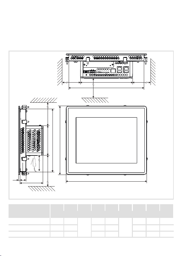
Abmessungen
Dimensions
Encombrements
Dimensiones
Dimensioni
a2
a1
> 40
> 40
b2
> 40 > 40
b
b1
!
e2
e3
p500, 17.8 cm (7”) 210.0 190.6
p500, 26.4 cm (10.4”) 282.0 262.6 240.0 220.6 82.0 4.0 22.0
p500, 38.1 cm (15”)
MA_p500 DE/EN/FR/ES/IT 2.0
> 40
e1
a a1 a2 b b1 b2 e1 e2 e3
390.0 370.8 310.0 290.6 87.0 6.0 27.0
182.0
155.0 135.6
9
a
p500_004
[mm]
82.0 4.0 22.0
104.0

Montage
Mounting
Montage
Montaje
Montaggio
m
1.
!
p500, 17.8 cm (7”) 194 139
p500, 26.4 cm (10.4”) 266 224
p500, 38.1 cm (15”) 374 294
MA_p500 DE/EN/FR/ES/IT 2.0
n
m n
[mm]
10
p500_006

2.
x Schraubspanner-Positionierhilfe
x Positioning aid for screw clamps
a
x
b
c
p500_007
MA_p500 DE/EN/FR/ES/IT 2.0
11

max. 20 Ncm
max. 1.7 lbin
3.
p500_008
MA_p500 DE/EN/FR/ES/IT 2.0
12

MA_p500 DE/EN/FR/ES/IT 2.0
13

© 10/2013
Lenze Automation GmbH
Hans-Lenze-Str. 1
D-31855 Aerzen
Germany
+49 (0)51 54 / 82-0
+49 (0)5154/82-2800
Lenze@Lenze.de
www.Lenze.com
Service Lenze Service GmbH
Breslauer Straße 3
D-32699 Extertal
Germany
00 80 00 / 24 4 68 77 (24 h helpline)
+49 (0)51 54 / 82-11 12
Service@Lenze.de
MA_p500.MVYDE/EN/FR/ES/IT2.0TD06
10987654321
 Loading...