


SMD
Frequency Interter
0.25 kW... 4.0 kW |
Operating Instructions |
EN |
|
|
|
|
|
|
|
Betriebsanleitung |
DE |
|
|
|
|
Instructions de mise en service |
FR |
|
|
|
|
Istruzioni di funzionamento |
IT |
|
|
|
|
Instrucciones de funcionamiento |
ES |
|
|
|
(13435747)
Copyright © 2013 - 2004 Lenze AC Tech Corporation
All rights reserved. No part of this manual may be reproduced or transmitted in any form without written permission from Lenze AC Tech Corporation. The information and technical data in this manual are subject to change without notice. Lenze AC Tech Corporation makes no warranty of any kind with respect to this material, including, but not limited to, the implied warranties of it’s merchantability and fitness for a given purpose. Lenze AC Tech Corporation assumes no responsibility for any errors that may appear in this manual.
All information given in this documentation has been carefully selected and tested for compliance with the hardware and software described. Nevertheless, discrepancies cannot be ruled out. We do not accept any responsibility nor liability for damages that may occur. Any necessary corrections will be implemented in subsequent editions.
This document printed in the United States

Contents
About these instructions............................................................................. |
2 |
|
|||
1 |
Safety information............................................................................... |
3 |
|
||
|
1.1 |
Pictographs used in these instructions....................................... |
4 |
|
|
2 |
Technical data..................................................................................... |
6 |
|
||
|
2.1 |
Standards and application conditions |
6 |
|
|
|
|
||||
|
2.2 |
Ratings |
7 |
|
|
|
|
||||
3 |
Installation |
........................................................................................... |
8 |
|
|
|
3.1 |
Mechanical ................................................................installation |
8 |
|
|
|
|
3.1.1 ............................................... |
Dimensions and mounting |
8 |
|
|
3.2 |
Electrical ...................................................................installation |
9 |
|
|
|
|
3.2.1 ....................Installation according to EMC requirements |
9 |
|
|
|
|
3.2.2 .............................................. |
Fuses/cable cross - sections |
9 |
|
|
|
3.2.3 ....................................................... |
Connection diagram |
10 |
|
|
|
3.2.4 ............................................................ |
Control terminals |
11 |
|
4 |
Commissioning................................................................................. |
12 |
|
||
|
4.1 |
Parameter ......................................................................setting |
12 |
|
|
|
4.2 |
Electronic ....................................programming module (EPM) |
13 |
|
|
|
4.3 |
Parameter .......................................................................menu |
13 |
|
|
5 |
Troubleshooting ...............................................and fault elimination |
18 |
|
||
Lenze 13435747 EDBSX03 v17 EN, DE, FR, IT, ES |
1 |
About these instructions
This documentation applies to the smd frequency inverter, and contains important technical data and describes installation, operation, and commissioning.
Please read the instructions before commissioning.
|
|
|
A |
|
B |
|
C |
|
D |
|
E F |
|||||||
|
|
|
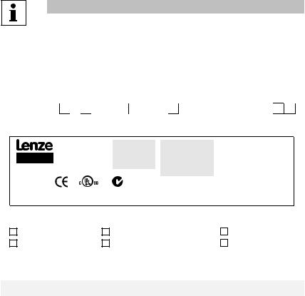
Type: |
|
|
|
|
|
|
|
|
|
+ |
|
|
|||
|
|
|
|
|
|
|
|
|
|
|
|
|
||||||
|
|
|
|
Input: 1(2)/N/PE AC |
Output: 3/PE AC |
For detailed information |
|
|||||||||||
|
|
|
ESMD751X2SFA |
|
230/240 V |
|
0-230 V |
refer to instruction |
|
|
|
|
|
|
|
|||
|
|
|
Id-No: 13XSAPID |
|
9.0 A |
|
4 A |
Manual SX03 |
|
|
|
|
|
|
|
|||
|
Made in USA |
|
|
|
|
50-60 Hz |
|
0.75 kW / 1HP |
SN: 13XSAPID012345678 |
|
|
|
|
|
||||
|
Inverter |
|
|
|
|
|
|
|
|
0 - 500 Hz |
ESMD751X2SFA 000XX |
XX |
|
XX |
|
|||
|
|
|
LISTED |
|
|
|
|
|
|
|
||||||||
|
|
|
5D81 |
|
|
|
1341308801234567 |
|
|
|
|
|
|
|
||||
|
smd - basic I/O |
|
IND. CONT. EQ. |
N10104 |
|
|
|
|
|
|
|
|
||||||
|
|
|
|
|
|
Z519 |
|
|
|
|
|
|
|
|
|
|
|
|
|
|
|
|
|
|
|
|
|
|
|
|
|
|
|
|
V0010 |
||
|
|
|
|
|
|
|
|
|
|
|
|
|
|
|
|
|||
|
A Certifications |
|
|
C Input Ratings |
|
|
E Hardware Version |
|||||||||||
|
B Type |
|
|
D Output Ratings |
F Software Version |
|||||||||||||
Scope of delivery |
Important |
|
|
• 1 smd inverter (ESMD...) |
After receipt of the delivery, check immediately whether the items |
with EPM installed |
delivered match the accompanying papers. Lenze does not accept any |
(refer to Section 4.2) |
liability for deficiencies claimed subsequently. |
• 1 Operating Instructions |
Claim |
|
• visible transport damage immediately to the forwarder. |
|
• visible deficiencies/incompleteness immediately to your Lenze |
|
representative. |
|
|
2 |
Lenze 13435747 EDBSX03 v17 EN, DE, FR, IT, ES |

Safety information
1Safety information
General
Some parts of Lenze controllers (frequency inverters, servo inverters, DC controllers) can be live, moving and rotating. Some surfaces can be hot.
Non-authorized removal of the required cover, inappropriate use, and incorrect installation or operation creates the risk of severe injury to personnel or damage to equipment.
All operations concerning transport, installation, and commissioning as well as maintenance must be carried out by qualified, skilled personnel (IEC 364 and CENELEC HD 384 or DIN VDE 0100 and IEC report 664 or DIN VDE0110 and national regulations for the prevention of accidents must be observed).
According to this basic safety information, qualified skilled personnel are persons who are familiar with the installation, assembly, commissioning, and operation of the product and who have the qualifications necessary for their occupation.
Application as directed
Drive controllers are components which are designed for installation in electrical systems or machinery. They are not to be used as appliances. They are intended exclusively for professional and commercial purposes according to EN 61000-3-2. The documentation includes information on compliance with the EN 61000-3-2.
When installing the drive controllers in machines, commissioning (i.e. the starting of operation as directed) is prohibited until it is proven that the machine complies with the regulations of the EC Directive 2006/42/EC (Machinery Directive); EN 60204 must be observed.
Commissioning (i.e. starting of operation as directed) is only allowed when there is compliance with the EMC Directive (2004/108/EEC).
The drive controllers meet the requirements of the Low Voltage Directive 2006/95/EEC. The harmonised standards of the series EN 50178/DIN VDE 0160 apply to the controllers.
Note: The availability of controllers is restricted according to EN 61800-3.These products can cause radio interference in residential areas. In this case, special measures can be necessary.
Installation
Ensure proper handling and avoid excessive mechanical stress. Do not bend any components and do not change any insulation distances during transport or handling. Do not touch any electronic components and contacts.
Controllers contain electrostatically sensitive components, which can easily be damaged by inappropriate handling. Do not damage or destroy any electrical components since this might endanger your health!
Electrical connection
When working on live drive controllers, applicable national regulations for the prevention of accidents (e.g. VBG 4) must be observed.
The electrical installation must be carried out according to the appropriate regulations (e.g. cable cross-sections, fuses, PE connection). Additional information can be obtained from the documentation. The documentation contains information about installation in compliance with EMC (shielding, grounding, filters and cables). These notes must also be observed for CE-marked controllers.
The manufacturer of the system or machine is responsible for compliance with the required limit values demanded by EMC legislation.
Lenze 13435747 EDBSX03 v17 EN, DE, FR, IT, ES |
3 |
Safety information
Operation
Systems including controllers must be equipped with additional monitoring and protection devices according to the corresponding standards (e.g. technical equipment, regulations for prevention of accidents, etc.). You are allowed to adapt the controller to your application as described in the documentation.
DANGER!
•After the controller has been disconnected from the supply voltage, live components and power connection must not be touched immediately, since capacitors could be charged. Please observe the corresponding notes on the controller.
•Do not continuously cycle input power to the controller more than once every 3 minutes.
•Please close all protective covers and doors during operation.
1.1Pictographs used in these instructions
Pictograph |
Signal word |
Meaning |
Consequences if ignored |
||
|
|
|
|
|
|
|
|
|
DANGER! |
Warning of Hazardous |
Reference to an imminent danger that may |
|
|
|
|
Electrical Voltage |
result in death or serious personal injury if |
|
|
|
|
|
the corresponding measures are not taken. |
|
|
|
|
|
|
|
|
|
WARNING! |
Impending or possible |
Death or injury |
|
|
|
|
danger for persons |
|
|
|
|
|
|
|
|
|
|
STOP! |
Possible damage to |
Damage to drive system or its surroundings |
|
|
|
|
equipment |
|
|
|
|
|
|
|
|
|
|
NOTE |
Useful tip |
If observed, it will make using the drive |
|
|
|
|||
|
|
|
|
|
easier |
|
|
|
|
|
|
|
|
|
|
|
|
4 |
Lenze 13435747 EDBSX03 v17 EN, DE, FR, IT, ES |
Safety information
Note for UL approved system with integrated controllers
UL warnings are notes which apply to UL systems. The documentation contains special information about UL.
|
• Integral solid state protection does not provide branch circuit protection. Branch |
|
circuit protection must be provided in accordance with the National Electrical |
|
Code and any additional local codes. The use of fuses or circuit breakers is the |
Warnings! |
only approved means for branch circuit protection. |
•When protected by CC and T Class Fuses, suitable for use on a circuit capable of delivering not more than 200,000 rms symmetrical amperes, at the maximum voltage rating marked on the drive.
•Additionally suitable when protected by a circuit breaker having an interrupting rating not less than 200,000 rms symmetrical amperes, at the maximum voltage rating marked on the drive. (Excludes ESMD113_4T_, ESMD112_2Y_, ESMD113 _ 2T_ , ESMD152 _ 2Y_ , ESMD153 _ 2T_ , ESMD222 _ 2Y_ , ESMD223_4T_, ESMD402_2T_, ESMD552_2T_, ESMD752_2T ESMD153_4T_, and ESMD183_4T_).
•Use minimum 75°C copper wire only, except for control circuits.
•For control circuits, use wiring suitable for NEC Class 1 circuits only.
•Torque Requirements are listed in section 3.2.3, Connection diagram.
•Shall be installed in a pollution degree 2 macro-environment.
DANGER!
Risk of Electric Shock! Capacitors retain charge for approximately 180 seconds after power is removed. Disconnect incoming power and wait at least 3 minutes before touching the drive.
WARNING!
The opening of branch-circuit protective device may be an indication that a fault has been interrupted. To reduce the risk of fire or electric shock, current carrying parts and other components of the controller should be examined and replaced if damaged.
Lenze 13435747 EDBSX03 v17 EN, DE, FR, IT, ES |
5 |
Technical data
2Technical data
2.1Standards and application conditions
|
|
Conformity |
CE |
Low Voltage (2006/95/EC) & EMC (2004/108/EC) Directives |
|
|
|
|
|
|
|
Approvals |
UL 508C |
Underwriters Laboratories - Power Conversion Equipment |
|
|
|
|
|
|
|
Max. permissible motor cable |
shielded: |
50 m (low-capacitance) |
|
|
length (1) |
unshielded: |
100 m |
|
|
Input voltage phase imbalance |
< 2% |
|
|
|
Humidity |
< 95% non-condensing |
|
|
|
|
|
|
|
|
Output frequency |
0...500 Hz |
|
|
|
|||
|
|
|
|
|
|
|
Environmental conditions |
Class 3K3 to EN 50178 |
|
|
|
|
Transport |
-25 … +70 °C |
|
|
|
|
|
|
|
Temperature range |
Storage |
-20 … +70 °C |
|
|
|
Operation |
0 … +55 °C (with 2.5 %/°C current derating above +40 °C) |
|
|
|
|
|
|
|
Installation height |
0 … 4000 m a.m.s.l. (with 5 %/1000 m current derating above 1000 m a.m.s.l.) |
|
|
|
|
|
|
|
|
Vibration resistance |
acceleration resistant up to 0.7 g 10... 150Hz |
|
|
|
Earth leakage current |
> 3.5 mA to PE |
|
|
|
|
|
|
|
|
Enclosure (EN 60529) |
IP 20 |
|
|
|
|
|
|
|
|
Protection measures against |
short circuit, earth fault, overvoltage, motor stalling, motor overload |
|
|
|
|
Total power |
|
|
|
Operation in public supply |
connected to |
Compliance with the requirements (2) |
|
|
the mains |
|
|
|
|
networks |
|
|
|
|
< 0.5 kW |
With mains choke |
|
|
|
(Limitation of harmonic currents |
||
|
|
according to EN 61000-3-2) |
0.5 … 1 kW |
With active filter (in preparation) |
|
|
|
|
|
|
|
|
> 1 kW |
Without additional measures |
|
|
Supply Conditions |
AC Mains |
Direct Connection |
|
|
|
|
|
|
|
|
TT |
For central grounded systems operation is permitted without |
|
|
|
restrictions |
|
|
|
|
|
|
|
|
|
|
For corner grounded 400/500V systems, operation is |
|
|
Power System |
TN |
possible, but reinforced insulation to control circuits is |
|
|
|
|
compromised. |
|
|
|
IT |
IT Mains power systems are not supported. |
|
|
|
|
|
(1)For compliance with EMC regulations, the permissible cable lengths may change.
(2)The additional measures described only ensure that the controllers meet the requirements of the EN 61000-3-2. The machine/system manufacturer is responsible for the compliance with the regulations of the machine!
6 |
Lenze 13435747 EDBSX03 v17 EN, DE, FR, IT, ES |

Technical data
2.2Ratings
Type |
Power |
|
Mains |
|
|
|
Output Current |
|
|
|
|
|
[kW] |
Voltage, frequency |
Current |
Ir |
|
Imax for 60 s |
|
|
|||
|
|
|
|
[A] |
|
|
|
|
|
|
|
|
|
|
|
[A](1) |
|
[A](2) |
[A](1) |
[A](2) |
|
|
|
ESMD251X2SFA |
0.25 |
|
|
3.4 |
1.7 |
|
1.6 |
2.6 |
2.4 |
|
|
|
|
|
|
|
|
|
|
|
|
|
|
ESMD371X2SFA |
0.37 |
1/N/PE |
230/240 V |
5.0 |
2.4 |
|
2.2 |
3.6 |
3.3 |
|
|
|
|
|
|
|
|
|
|
|
|
||
ESMD551X2SFA |
0.55 |
6.0 |
3.0 |
|
2.8 |
4.5 |
4.2 |
|
|
||
2/PE |
230/240 V |
|
|
|
|||||||
|
|
(180 V - 0% … 264 V + 0 %) |
|
|
|
|
|
|
|
|
|
ESMD751X2SFA |
0.75 |
9.0 |
4.0 |
|
3.7 |
6.0 |
5.5 |
|
|
||
50/60 Hz |
|
|
|
||||||||
|
|
(48 Hz - 0 % … 62 Hz + 0 %) |
|
|
|
|
|
|
|
|
|
ESMD152X2SFA |
1.5 |
14.0 |
7.0 |
|
6.4 |
10.5 |
9.6 |
|
|
||
|
|
|
|
|
|||||||
|
|
|
|||||||||
|
|
|
|
|
|
|
|
|
|
|
|
ESMD222X2SFA |
2.2 |
|
|
21.0 |
9.5 |
|
8.7 |
14.3 |
13.1 |
|
|
|
|
|
|||||||||
|
|
|
|
|
|
|
|
|
|
|
|
ESMD371X2TXA |
0.37 |
|
|
2.7 |
2.4 |
|
2.2 |
3.6 |
3.3 |
|
|
|
|
|
|
|
|
|
|
|
|
|
|
ESMD751X2TXA |
0.75 |
|
|
5.1 |
4.2 |
|
3.9 |
6.3 |
5.9 |
|
|
|
|
|
|
|
|
|
|
|
|
|
|
ESMD112X2TXA |
1.1 |
3/PE |
230/240 V |
6.9 |
6.0 |
|
5.5 |
9.0 |
8.3 |
|
|
|
|
|
|
|
|
|
|
|
|
||
ESMD152X2TXA |
1.5 |
(180 V - 0% … 264 V + 0 %) |
7.9 |
7.0 |
|
6.4 |
10.5 |
9.6 |
|
|
|
50/60 Hz |
|
|
|
||||||||
|
|
|
|
|
|
|
|
|
|
||
ESMD222X2TXA |
2.2 |
(48 Hz - 0 % … 62 Hz + 0 %) |
11.0 |
9.6 |
|
8.8 |
14.4 |
13.2 |
|
|
|
|
|
|
|
|
|||||||
|
|
|
|
|
|
|
|
|
|
|
|
ESMD302X2TXA |
3.0 |
|
|
13.5 |
12.0 |
|
11.0 |
18.0 |
16.5 |
|
|
|
|
|
|
|
|
|
|
|
|
|
|
ESMD402X2TXA |
4.0 |
|
|
17.1 |
15.2 |
|
14.0 |
22.8 |
21.0 |
|
|
|
|
|
|
|
|
|
|
|
|
|
|
(1)For rated mains voltage and carrier frequencies 4, 6, 8 kHz
(2)For rated mains voltage and carrier frequency 10 kHz
Lenze 13435747 EDBSX03 v17 EN, DE, FR, IT, ES |
7 |

Installation
3Installation
3.1Mechanical installation
3.1.1Dimensions and mounting
|
|
|
|
|
>50 |
|
|
|
|
|
b2 |
|
|
|
|
|
|
4 x M4 |
|
|
|
|
>15 |
>15 |
|
|
2,4 Nm |
|
b1 b |
|
|
|
|||
|
|
|
|
|
|
|||
21 lb-in |
|
|
|
|
|
|
||
|
|
|
|
|
|
|
||
|
a1 |
|
|
|
>50 |
|
|
|
|
a |
|
c |
|
|
|
|
|
|
|
|
|
|
|
|
smd002 |
|
Type |
a [mm] |
a1 [mm] |
b [mm] |
b1 [mm] |
b2 [mm] |
c [mm] |
m [kg] |
|
ESMD251X2SFA |
93 |
84 |
146 |
128 |
17 |
83 |
0.5 |
|
ESMD371X2SFA |
||||||||
|
|
|
|
|
|
|
||
ESMD551X2SFA |
93 |
84 |
146 |
128 |
17 |
92 |
0.6 |
|
ESMD751X2SFA |
||||||||
|
|
|
|
|
|
|
||
ESMD152X2SFA |
114 |
105 |
146 |
128 |
17 |
124 |
1.2 |
|
ESMD222X2SFA |
114 |
105 |
146 |
128 |
17 |
140 |
1.4 |
|
ESMD371X2TXA |
93 |
84 |
146 |
128 |
17 |
83 |
0.5 |
|
ESMD751X2TXA |
93 |
84 |
146 |
128 |
17 |
92 |
0.6 |
|
ESMD112X2TXA |
93 |
84 |
146 |
128 |
17 |
141 |
1.2 |
|
ESMD152X2TXA |
||||||||
|
|
|
|
|
|
|
||
ESMD222X2TXA |
114 |
105 |
146 |
128 |
17 |
140 |
1.4 |
|
ESMD302X2TXA |
114 |
105 |
146 |
128 |
17 |
171 |
1.9 |
|
ESMD402X2TXA |
114 |
105 |
146 |
100 |
17 |
171 |
1.7 |
WARNING!
Drives must not be installed where subjected to adverse environmental conditions such as: combustible, oily, or hazardous vapors or dust; excessive moisture; excessive vibration or excessive temperatures. Contact Lenze for more information.
8 |
Lenze 13435747 EDBSX03 v17 EN, DE, FR, IT, ES |
Installation
3.2Electrical installation
3.2.1Installation according to EMC requirements
EMC |
|
|
|
|
|
|
|
|
|
|
|
|
|
Compliance with EN 61800-3/A11 |
|
|
|
|
|
|
|
|
|
|
|
|
|
|
|
|
|
|
|
|
|
|
|
|
|
|
|
Noise emission |
|
|
|
|
|
|
|
|
|
|
|
|
|
Compliance with limit value class A according to EN 55011 if installed in a control |
|
|
|
|
|
|
|
|
|
|
|
|
|
cabinet with the appropriate footprint filter and the motor cable length does not |
|
B |
|
|
|
|
|
|
|
|
|
|
|
exceed 10m |
|
|
|
|
|
|
|
|
|
|
|
|
|
|
|
|
|
|
|
|
|
|
E |
|
|
|
|
A Screen clamps |
|
|
|
|
|
|
|
||||||
|
|
|
|
|
|
|
|
|
|
|
|
||
B |
Control cable |
|
|
|
|
|
C |
|
|
|
|
|
|
|
|
|
|
|
|
|
|
||||||
C Low-capacitance motor cable |
|
|
|
|
|
|
|
|
|
|
|
|
|
|
|
|
|
|
|
|
D |
|
|
||||
|
|
|
A |
|
|
|
|
|
|
||||
|
(core/core < 75 pF/m, core/screen < 150 pF/m) |
|
|
|
|
|
|
|
|
|
|
|
|
|
|
|
|
|
|
|
|
|
|
|
|
|
|
D |
Electrically conductive mounting plate |
|
|
|
|
|
|
|
|
|
|
|
|
E |
Filter (if required) |
|
|
|
|
|
|
|
Tmd005 |
|
|
||
|
|
|
|
|
|
|
|
|
|
|
|||
3.2.2Fuses/cable cross-sections (1)
Type |
|
Recommendations |
|
|
E.l.c.b.(2) |
||
|
Fuse |
Miniature |
Fuse (3) or |
|
Input Power Wiring |
|
|
|
|
circuit |
Breaker(6) |
|
(L1, L2/N, L3, PE) |
|
|
|
|
breaker(5) |
(N. America) |
|
[mm²] |
[AWG] |
|
|
|
|
|
|
|||
|
|
|
|
|
|
|
|
ESMD251X2SFA … ESMD551X2SFA |
M10 A |
C10 A |
10 A |
|
2.5 |
14 |
|
ESMD371X2TXA … ESMD112X2TXA |
|
|
|||||
|
|
|
|
|
|
|
|
|
|
|
|
|
|
|
|
ESMD152X2TXA |
M16 A |
C16 A |
12 A |
|
2.5 |
14 |
|
|
|
|
|
|
|
|
> 30 mA |
ESMD751X2SFA, ESMD222X2TXA |
M16 A |
C16 A |
15 A |
|
2.5 |
14 |
|
|
|
||||||
|
|
|
|
|
|
|
|
ESMD152X2SFA, ESMD302X2TXA |
M20 A |
C20 A |
20 A |
|
4 (4) |
12 |
|
ESMD222X2SFA, ESMD402X2TXA |
M25 A |
C25 A |
25 A |
|
6 (4) |
10 |
|
(1)Observe the applicable local regulations.
(2)Pulse-current or universal-current sensitive earth leakage circuit breaker.
(3)UL Class CC or T fast-acting current-limiting type fuses, 200,000 AIC, required. Bussman KTK-R, JJN, JJS or equivalent.
(4)Connection without end ferrules or with attached pin end connectors.
(5)Installations with high fault current due to large supply mains may require a type D circuit breaker.
(6)Thermomagnetic type breakers preferred.
Observe the following when using E.l.c.b:
•Installation of E.l.c.b only between supplying mains and controller.
•The E.l.c.b can be activated by:
-capacitive leakage currents between the cable screens during operation (especially with long, screened motor cables)
-connecting several controllers to the mains at the same time
-RFI filters
Lenze 13435747 EDBSX03 v17 EN, DE, FR, IT, ES |
9 |
Installation
Installation After a Long Period of Storage
STOP!
Severe damage to the drive can result if it is operated after a long period of storage or inactivity without reforming the DC bus capacitors.
If input power has not been applied to the drive for a period of time exceeding three years (due to storage, etc), the electrolytic DC bus capacitors within the drive can change internally, resulting in excessive leakage current. This can result in premature failure of the capacitors if the drive is operated after such a long period of inactivity or storage.
In order to reform the capacitors and prepare the drive for operation after a long period of inactivity, apply input power to the drive for 8 hours prior to actually operating the motor.
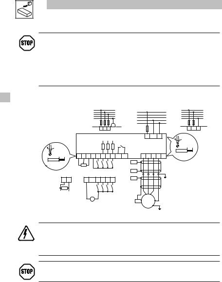
3.2.3Connection diagram
|
|
|
|
|
|
|
3/PE 180V - 0%… 264V + 0 % |
1/N/PE 180 V - …0 %264 V + |
0 % |
2/PE 180V - 0%… 264V + 0 |
||
|
|
|
|
|
|
|
48 Hz… 62 Hz |
48 Hz… |
62 Hz |
|
48 Hz… 62 Hz |
|
|
|
|
|
|
|
|
L1 |
L1 |
|
|
|
L1 |
|
|
|
|
|
|
|
L2 |
|
|
|
L2 |
|
|
|
|
|
|
|
|
L3 |
L2 |
|
|
|
L3 |
|
|
|
|
|
|
|
N |
|
|
|
N |
|
|
|
|
|
|
|
|
PE |
L3 |
|
|
|
PE |
|
|
|
|
|
|
|
|
N |
|
|
|
|
|
|
|
|
|
|
|
PE |
PE |
|
|
|
L1L2/NPE |
|
|
|
|
|
|
|
L1L2L3 |
|
|
|
|
|
|
|
|
|
smd |
|
|
L1 L2/NPE |
|
|
|||
|
|
|
|
|
|
|
|
|
|
|
|
0.5 Nm / 4.5 lb-in |
|
|
|
|
COM |
AIN |
+10V |
+12V |
|
|
|
|
6 mm / 0.24 in |
|
0.2 Nm / 2 lb-in |
U |
V |
W PE PE |
|
|
||||||
|
6 mm / 0.24 in |
7 |
8 |
9 20 28 E1 E2 E3 K14 K12 |
|
|
||||||
|
|
|
|
|
|
|
|
|
|
|||
< 1 |
mm² / |
AWG 26… 16 |
|
|
|
|
|
PES |
|
|
|
|
|
|
|
|
1k … |
10k |
PES |
|
|
|
|
||
|
|
|
|
|
|
|
|
|
|
|
|
|
|
|
7 |
8 |
|
|
7 |
28 E1E2 E3 |
PES |
|
|
PE |
|
|
|
|
|
|
|
|
|
|||||
|
|
250 |
|
|
|
|
|
|
|
|
|
|
|
|
0 ...20 mA |
|
|
|
|
|
|
|
|
|
|
|
|
4 ...20 mA |
|
|
_ |
+ |
PES |
M |
PE |
|
|
|
|
|
|
|
|
|
|
|
|||||
|
|
|
|
|
|
+12 VDC - 0 % |
|
3~ |
|
|
|
|
|
|
|
|
|
|
|
… |
|
|
|
|
|
|
|
|
|
|
+30 VDC + 0 % |
|
|
|
|
|
||
smd003
DANGER!
•Hazard of electrical shock! Circuit potentials are up to 240 VAC above earth ground. Capacitors retain charge after power is removed. Disconnect power and wait until the voltage between B+ and B- is 0 VDC before servicing the drive.
•Do not connect mains power to the output terminals (U,V,W)! Severe damage to the drive will result.
•Do not cycle mains power more than once every three minutes. Damage to the drive will result.
STOP!
If the kVA rating of the AC supply transformer is greater than 10 times the input kVA rating of the drive(s), an isolation transformer or 2-3% input line reactor must be added to the line side of the drive(s).
10 |
Lenze 13435747 EDBSX03 v17 EN, DE, FR, IT, ES |
Installation
3.2.4Control terminals
Terminal |
Data for control connections (printed in bold = Lenze setting) |
|
|
|
||
|
|
|
|
|
|
|
7 |
Reference potential |
|
|
|
|
|
|
|
|
|
|
|
|
8 |
Analog input |
input resistance: >50 kΩ |
|
|
|
|
|
0 … 10 V (changeable under C34) |
(with current signal: 250 Ω) |
|
|
|
|
9 |
Internal DC supply for setpoint potentiometer |
+10 V, max. 10 mA |
|
|
|
|
|
|
|
|
|
|
|
20 |
Internal DC supply for digital inputs |
+12 V, max. 20 mA |
|
|
|
|
|
|
|
|
|
|
|
28 |
Digital input Start/Stop |
LOW = |
Stop |
|
|
|
|
|
HIGH = |
Run Enable |
kΩ |
|
|
|
|
|
|
|||
E1 |
Digital input configurable with CE1 |
HIGH = |
JOG1 active |
|
|
|
|
Activate fixed setpoint 1 (JOG1) |
|
|
= 3.3 |
|
|
E2 |
Digital input configurable with CE2 |
LOW = |
CW rotation |
|
|
|
|
Direction of rotation |
HIGH = |
CCW rotation |
i |
|
|
|
R |
|
|
|||
E3 |
Digital input configurable with CE3 |
HIGH = |
DCB active |
|
|
|
|
Activate DC injection brake (DCB) |
|
|
|
|
|
|
|
|
|
|
|
|
K12 |
Relay output (normally-open contact) |
AC 250 V / 3 A |
|
|
|
|
|
configurable with C08 |
DC 24 V / 2 A … 240 V / 0.22 A |
|
|
|
|
|
|
|
|
|||
K14 |
Fault (TRIP) |
|
|
|
|
|
|
|
|
|
|
|
|
NOTE
LOW = 0 to +3V, HIGH = +12 to +30V.
Protection against contact
•All terminals have basic isolation (single insulating distance)
•Protection against contact can only be ensured by additional measures (i.e. double insulation)
STOP!
In the case of a Spinning Motor:
To bring free-wheeling loads such as fans to a rest before starting the drive, use the DC injection braking function (“Auto-DCB”). Starting a drive into a freewheeling motor creates a direct short-circuit and may result in damage to the drive.
Confirm motor suitability for use with DC injection braking.
Lenze 13435747 EDBSX03 v17 EN, DE, FR, IT, ES |
11 |
Commissioning
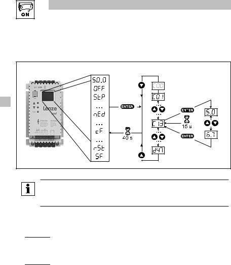
4Commissioning
4.1Parameter setting
Status/fault messages |
Change parameters |
|
smd004 |
NOTE |
|
If the password function is enabled, the password must be entered into C00 to access the parameters. C00 will not appear unless the password function is enabled. Refer to C94.
4.2Electronic programming module (EPM)
Tmd007

The EPM contains the controller’s memory. Whenever parameter settings are changed, the values are stored in the EPM. It can be removed, but must be installed for the controller to operate (a missing EPM will trigger an F1 fault). The controller ships with protective tape over the EPM that can be removed after installation.
An optional EPM Programmer (EEPM1RA) is available that allows: the controller to be programmed without power; OEM settings to be default settings; fast copying of EPMs when multiple controllers require identical settings. It can also store up to 60 custom parameter files for even faster controller programming.
12 |
Lenze 13435747 EDBSX03 v17 EN, DE, FR, IT, ES |
Commissioning
4.3Parameter menu
Code |
|
|
Possible Settings |
IMPORTANT |
|
|
|||
No. |
Name |
|
Lenze |
Selection |
|
||||
|
|
|
|
|
|||||
C00 |
Password entry |
0 |
0 |
999 |
Visible only when password is active |
|
|||
|
|
|
|
|
|
(see C94) |
|
||
C01 |
Setpoint source |
|
|
0 |
Analog input (terminal 8; see C34) |
|
|
|
|
|
|
|
|
|
|
|
|
|
|
|
|
|
|
1 |
Code c40 |
Observe notes about c40 |
|
||
|
|
|
|
|
|
|
|
|
|
C02 |
Load Lenze setting |
|
|
0 |
No action/loading complete |
• C02 = 1... 4 only possible with OFF |
|
||
|
|
|
|
|
|
|
|
||
|
|
|
|
1 |
Load 50 Hz Lenze settings |
• C02 = 2 : C11, C15 = 60 Hz |
|
||
|
|
|
|
|
|
|
|
|
|
|
|
|
|
2 |
Load 60 Hz Lenze settings |
|
|
|
|
|
|
|
|
|
|
|
|
||
|
|
|
|
|
|
|
|
|
|
|
|
|
|
3 |
Load OEM settings |
|
|
|
|
|
|
|
|
|
|
|
|
||
|
|
|
|
|
|
|
|
|
|
|
|
|
|
4 |
Translate |
|
|
|
|
|
|
|
|
|
|
|
|
|
|
|
|
|
|
WARNING! |
|
|
|
|
|
|
|
|
|
C02 = 1... 3 overwrites all settings! TRIP circuitry may be disabled! |
|
||||
|
|
|
|
Check codes CE1...CE3. |
|
|
|
|
|
|
|
|
|
|
|
|
|
|
|
|
|
|
|
NOTE |
|
|
|
|
|
|
|
|
|
|
|
|
|
||
|
|
|
|
If an EPM that contains data from a previous software version is installed, C02 = |
|
||||
|
|
|
|
4 converts the data to the current version. |
|
||||
|
|
|
|
|
|||||
|
|
|
|
|
|
|
|
|
|
CE1 |
Configuration - |
1 |
1 |
Activate fixed setpoint 1 (JOG1) |
• Use C37...C39 to adjust fixed setpoints |
|
|||
|
Digital Input E1 |
|
|
|
|
|
|||
|
|
|
|
2 |
Activate fixed setpoint 2 (JOG2) |
• Activate JOG3: Both terminals = HIGH |
|
||
|
|
|
|
|
|
|
|
||
|
|
|
|
|
|
|
|
|
|
|
|
|
|
3 |
DC braking (DCB) |
See also C36 |
|
||
|
|
|
|
4 |
Direction of rotation |
LOW = CW rotation |
|
|
|
|
|
|
|
|
|
HIGH = CCW rotation |
|
||
|
|
|
|
5 |
Quick stop |
Controlled deceleration to standstill, |
|
|
|
|
|
|
|
|
|
active LOW; Set decel rate in C13 or |
|
||
|
|
|
|
|
|
c03 |
|
|
|
|
|
|
|
6 |
CW rotation |
CW rotation = LOW and CCW rotation = |
|
||
|
|
|
|
7 |
CCW rotation |
LOW: Quick stop; Open-circuit protected |
|
||
CE2 |
Configuration - |
4 |
|
||||||
|
Digital Input E2 |
|
|
8 |
UP (setpoint ramp-up) |
UP = LOW and DOWN = LOW: Quick |
|
|
|
|
|
|
|
|
|||||
|
|
|
|
|
|
stop; Use momentary NC contacts |
|
||
|
|
|
|
9 |
DOWN (setpoint ramp-down) |
|
|||
|
|
|
|
|
|
|
|
||
|
|
|
|
10 |
TRIP set |
Active LOW, triggers EER (motor coasts |
|
||
|
|
|
|
|
|
to standstill) |
|
||
CE3 |
Configuration - |
3 |
|
|
NOTE: NC thermal contact from the |
|
|||
|
Digital Input E3 |
|
|
|
|
motor can be used to trigger this input |
|
||
|
|
|
|
11 |
TRIP reset |
See also c70 |
|
|
|
|
|
|
|
12 |
Accel/decel 2 |
See c01 and c03 |
|
|
|
|
|
|
|
13 |
Deactivate PI |
Disables PI function for manual control |
|
|
|
|
|
|
|
14 |
Activate fixed PI setpoint 1 |
• Use C37...C39 to adjust fixed |
|
|
|
|
|
|
|
|
|
setpoints |
|
||
|
|
|
|
15 |
Activate fixed PI setpoint 2 |
• Activate fixed PI setpoint 3: Both |
|
||
|
|
|
|
|
|
terminals = HIGH |
|
||
|
|
|
|
NOTE |
|
|
|
|
|
|
|
|
|
|
|
|
|
||
A CFG fault will occur under the following conditions:
•E1...E3 settings are duplicated (each setting can only be used once)
•One input is set to UP and another is not set to DOWN, or vice-versa
Lenze 13435747 EDBSX03 v17 EN, DE, FR, IT, ES |
13 |
|
|
Commissioning |
|
|
Code |
|
Possible Settings |
IMPORTANT |
|
No. |
Name |
Lenze Selection |
||
|
||||
C08 |
Configuration - |
1 Relay is energized if |
|
|
|
Relay output |
0 Ready |
|
1Fault
2Motor is running
3Motor is running - CW rotation
4Motor is running - CCW rotation
5 Output frequency = 0 Hz
6Frequency setpoint reached
7Threshold (C17) exceeded
8Current limit (motor or generator mode) reached
9Feedback within min/max alarm (d46, d47) range
10Feedback outside min/max alarm (d46, d47) range
C10 |
Minimum output |
0.0 |
0.0 |
{Hz} |
500 |
• |
Output frequency at 0% analog |
|
frequency |
|
|
|
|
|
setpoint |
|
|
|
|
|
|
• |
C10 not active for fixed setpoints or |
|
|
|
|
|
|
|
setpoint selection via c40 |
|
|
|
|
|
|
|
|
C11 |
Maximum output |
50.0 |
7.5 |
{Hz} |
500 |
• Output frequency at 100% analog |
|
|
frequency |
|
|
|
|
|
setpoint |
|
|
|
|
|
|
• C11 is never exceeded |
|
|
|
|
|
|
|
|
|
|
|
|
WARNING! |
|
|
|
|
|
|
|
Consult motor/machine manufacturer before operating above rated frequency. |
||||
|
|
|
Overspeeding the motor/machine may cause damage to equipment and injury to |
||||
|
|
|
personnel! |
|
|
|
|
|
|
|
|
|
|
|
|
C12 |
Acceleration time 1 |
5.0 |
0.0 |
{s} |
999 |
• C12 = frequency change 0 Hz...C11 |
|
|
|
|
|
|
|
• C13 = frequency change C11...0 Hz |
|
C13 |
Deceleration time 1 |
5.0 |
0.0 |
{s} |
999 |
• |
For S-ramp accel/decel, adjust c82 |
|
|
|
|
|
|
|
|
C14 |
Operating Mode |
2 |
0 |
Linear characteristic with |
|
• |
Linear characteristic: for standard |
|
|
|
|
Auto-Boost |
|
|
applications |
|
|
|
|
|
|
• |
Square-law characteristic: for fans |
|
|
|
1 Square-law characteristic with |
|
|||
|
|
|
|
|
and pumps with square-law load |
||
|
|
|
|
Auto-Boost |
|
|
|
|
|
|
|
|
|
characteristic |
|
|
|
|
|
|
|
|
|
|
|
|
2 Linear characteristic with constant |
• Auto boost: load-dependent output |
|||
|
|
|
|
Vmin boost |
|
|
voltage for low-loss operation |
3Square-law characteristic with constant Vmin boost
C15 |
V/f reference point |
50.0 |
25.0 |
{Hz} |
999 |
|
|
|
Set the rated motor frequency |
|
|
|
|
|
(nameplate) for standard applications |
||
C16 |
Vmin boost |
6.0 |
0.0 |
{%} |
40.0 |
|
(optimization of |
|
Set after commissioning: The unloaded |
||
|
torque behavior) |
|
|||
|
|
|
motor should run at slip frequency |
|
|
|
|
|
(approx. 5 Hz), increase C16 until |
|
|
|
|
|
motor current (C54) = 0.8 x rated motor |
||
|
|
|
current |
|
smd006 |
C17 |
Frequency threshold 0.0 0.0 |
{Hz} |
500 See C08, selection 7 |
|
(Qmin) |
|
Reference: setpoint |
14 |
|
Lenze 13435747 EDBSX03 v17 EN, DE, FR, IT, ES |
|
|
|
|
|
|
Commissioning |
|
|
|
|
|||
|
|
|
|
|
|
|
|
|
|
|
||
|
|
|
|
|
|
|
|
|
|
|
||
Code |
|
Possible Settings |
|
|
IMPORTANT |
|
|
|||||
No. |
Name |
Lenze |
Selection |
|
|
|
|
|||||
|
|
|
|
|
|
|
||||||
C18 |
Chopper frequency |
2 |
0 |
4 kHz |
|
• |
As chopper frequency is increased, |
|
|
|||
|
|
|
|
|
|
|
|
motor noise is decreased |
|
|
||
|
|
|
1 |
6 kHz |
|
|
|
|
||||
|
|
|
|
• |
Observe derating in Section 2.2 |
|
|
|||||
|
|
|
|
|
|
|
|
|
||||
|
|
|
2 |
8 kHz |
|
• |
Automatic derating to 4 kHz at 1.2 xIr |
|
|
|||
|
|
|
3 |
10 kHz |
|
|
|
|
|
|
|
|
|
|
|
|
|
|
|
|
|
|
|||
C21 |
Slip compensation |
0.0 |
0.0 |
|
{%} |
40.0 |
Change C21 until the motor speed no |
|
|
|||
|
|
|
|
|
|
|
longer changes between no load and |
|
|
|||
|
|
|
|
|
|
|
maximum load |
|
|
|||
|
|
|
|
|
|
|
|
|
|
|
||
C22 |
Current limit |
150 |
30 |
|
{%} |
150 |
• |
When the limit value is reached, either |
|
|
||
|
|
|
Reference: smd rated output current |
|
the acceleration time increases or the |
|
|
|||||
|
|
|
|
output frequency decreases |
|
|
||||||
|
|
|
|
|
|
|
|
|
|
|||
C24 |
Accel boost |
0.0 |
0.0 |
|
{%} |
20.0 |
Accel boost is only active during |
|
|
|||
|
|
|
|
|
|
|
acceleration |
|
|
|||
|
|
|
|
|
|
|
|
|
||||
C31 |
Analog input dead |
0 |
0 |
Enabled |
|
C31 = 0 activates dead band for analog |
|
|
||||
|
band |
|
|
|
|
|
input. When analog signal is within dead |
|
|
|||
|
|
|
|
|
|
|
band, controller’s output = 0.0 Hz and |
|
|
|||
|
|
|
1 |
Disabled |
|
|
|
|||||
|
|
|
|
display will read STP |
|
|
||||||
|
|
|
|
|
|
|
|
|
||||
|
|
|
|
|
|
|
|
|
|
|
|
|
C34 |
Configuration - |
0 |
0 |
0...10 V |
|
|
|
|
|
|
|
|
|
analog input |
|
|
|
|
|
|
|
|
|
|
|
|
|
1 |
0...5 V |
|
|
|
|
|
|
|
||
|
|
|
|
|
|
|
|
|
|
|||
|
|
|
|
|
|
|
|
|
|
|
|
|
|
|
|
2 |
0... |
20 mA |
|
|
|
|
|
|
|
|
|
|
|
|
|
|
|
|
|
|
|
|
|
|
|
3 |
4... |
20 mA |
|
|
|
|
|
|
|
|
|
|
|
|
|
|
|
|
||||
|
|
|
4 |
4...20 mA monitored |
|
Will trigger SD5 fault if signal falls below |
|
|
||||
|
|
|
|
|
|
|
2 mA |
|
|
|||
C36 |
Voltage - DC |
4.0 |
0.0 |
|
{%} |
50.0 |
• |
See CE1...CE3 and c06 |
|
|
||
|
injection brake |
|
|
|
|
|
• |
Confirm motor suitability for use with |
|
|
||
|
(DCB) |
|
|
|
|
|
|
DC braking |
|
|
||
|
|
|
|
|
|
|
|
|
|
|||
C37 |
Fixed setpoint 1 |
20.0 |
0.0 |
|
{Hz} |
999 |
When PI is active (see d38), C37...C39 |
|
|
|||
|
(JOG 1) |
|
|
|
|
|
are fixed PI setpoints |
|
|
|||
|
|
|
|
|
|
|
|
|
|
|
|
|
C38 |
Fixed setpoint 2 |
30.0 |
0.0 |
|
{Hz} |
999 |
|
|
|
|
|
|
|
(JOG 2) |
|
|
|
|
|
|
|
|
|
|
|
C39 |
Fixed setpoint 3 |
40.0 |
0.0 |
|
{Hz} |
999 |
|
|
|
|
|
|
|
(JOG 3) |
|
|
|
|
|
|
|
|
|
|
|
C46 |
Frequency setpoint |
|
0.0 |
|
{Hz} |
500 |
Display: Setpoint via analog input, |
|
|
|||
|
|
|
|
|
|
|
function UP/DOWN |
|
|
|||
|
|
|
|
|
|
|
|
|
|
|||
C50 |
Output frequency |
|
0.0 |
|
{Hz} |
500 |
Display |
|
|
|||
|
|
|
|
|
|
|
|
|
|
|||
C53 |
DC bus voltage |
|
0.0 |
|
{%} |
255 |
Display |
|
|
|||
|
|
|
|
|
|
|
|
|
|
|||
C54 |
Motor current |
|
0.0 |
|
{%} |
255 |
Display |
|
|
|||
|
|
|
|
|
|
|
|
|
|
|||
C59 |
PI feedback |
|
c86 |
|
{%} |
c87 |
Display |
|
|
|||
|
|
|
|
|
|
|
|
|
|
|
|
|
C70 |
Proportional gain |
5.0 |
0.0 |
|
{%} |
99.9 |
|
|
|
|
|
|
|
|
|
|
|
|
|
|
|
|
|
|
|
C71 |
Integral gain |
0.0 |
0.0 |
|
{s} |
99.9 |
|
|
|
|
|
|
|
|
|
|
|
|
|
|
|
|
|||
C94 |
User password |
0 |
0 |
|
|
999 |
When set to a value other than 0, |
|
|
|||
|
|
|
|
|
|
|
must enter password at C00 to access |
|
|
|||
|
|
|
Changing from “0” (no password), |
|
parameters |
|
|
|||||
|
|
|
value will start at 763 |
|
|
|
|
|
|
|
||
|
|
|
|
|
|
|
|
|
|
|||
C99 |
Software version |
|
|
|
|
|
Display, format: x.yz |
|
|
|||
|
|
|
|
|
|
|
|
|
||||
Lenze 13435747 EDBSX03 v17 EN, DE, FR, IT, ES |
|
|
15 |
|
|
|||||||
Commissioning
|
|
Code |
|
Possible Settings |
|
|
|
|
|
IMPORTANT |
|||||
|
|
No. |
Name |
Lenze |
Selection |
|
|
|
|
|
|||||
|
|
|
|
|
|
|
|
|
|
|
|||||
|
|
C01 |
Acceleration time 2 |
5.0 |
0.0 |
{s} |
999 |
• |
Activated using CE1...CE3 |
||||||
|
|
|
|
|
|
|
|
• |
c01 = frequency change 0 Hz...C11 |
||||||
|
|
C03 |
Deceleration time 2 |
5.0 |
0.0 |
{s} |
999 |
• |
c03 = frequency change C11...0 Hz |
||||||
|
|
|
|
|
|
|
|
• For S-ramp accel/decel, adjust c82 |
|||||||
|
|
|
|
|
|
|
|
|
|
|
|
|
|
||
|
|
C06 |
Holding time - |
0.0 |
0.0 |
{s} |
999 |
• |
Automatic motor braking below 0.1 Hz |
||||||
|
|
|
automatic DC |
|
|
|
|
|
by means of motor DC current for the |
||||||
|
|
|
injection brake |
|
0.0 = not active |
|
|
entire holding time (afterwards: U, V, |
|||||||
|
|
|
(Auto-DCB) |
|
999 = continuous brake |
|
|
W inhibited) |
|
|
|
||||
|
|
|
|
|
|
|
|
• |
Confirm motor suitability for use with |
||||||
|
|
|
|
|
|
|
|
|
DC braking |
|
|
|
|||
|
|
|
|
|
|
|
|
|
|
|
|
|
|
|
|
|
|
C20 |
I2t switch-off |
100 |
30 |
{%} |
100 |
• |
Triggers |
0C6 fault when motor |
|||||
|
|||||||||||||||
|
|
|
(thermal motor |
|
100% = smd rated output current |
|
|
current exceeds C20 for too long |
|||||||
|
|
|
monitoring) |
|
|
|
|||||||||
|
|
|
|
|
C20 = motor current rating x 100 |
||||||||||
|
|
|
|
|
|
|
|
||||||||
|
|
|
|
|
|
|
|
|
|
|
smd output rating |
||||
|
|
|
|
|
|
|
|
Example: if motor = 6.4amps and smd = |
|||||||
|
|
|
|
|
|
|
|
7.0amps, then C20 = 91% |
|||||||
|
|
|
|
|
|
|
|
|
|
|
|
|
|
|
|
|
|
|
|
|
WARNING! |
|
|
|
|
|
|
|
|
|
|
|
|
|
|
|
Maximum setting is rated motor current (see nameplate). Does not provide full |
||||||||||
|
|
|
|
|
motor protection! |
|
|
|
|
|
|
|
|
|
|
|
|
|
|
|
|
|
|
|
|
|
|
|
|
|
|
|
|
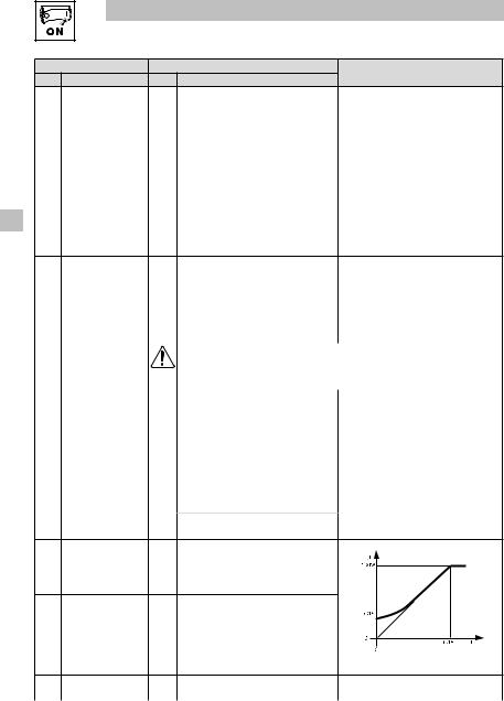
C21 |
Motor Overload |
00 |
00 |
Speed Compensation |
|
|
Ir |
|
1 |
|
|
|
|
|
|
|
Type |
|
|
Reduces the allowable continuous |
100% |
|
|
|
|
|
|||
|
|
|
|
|
|
|
|
|
|
|
|
|
|
||
|
|
|
|
|
|
current when operating below 30Hz. |
|
|
|
|
0 |
|
|
|
|
|
|
|
|
|
|
|
|
|
60% |
|
|
|
|
|
|
|
|
|
|
|
01 |
No Speed Compensation |
|
|
|
|
|
|
|||
|
|
|
|
|
|
|
|
|
|
|
|
|
|
||
|
|
|
|
|
|
Example: Motor is cooled by |
|
|
|
|
|
|
|
|
|
|
|
|
|
|
|
forced ventilation as apposed to |
|
|
|
|
|
|
|
|
|
|
|
|
|
|
|
shaft mounted, self cooling fans. |
|
|
|
|
|
|
|
|
|
|
|
|
|
|
|
|
|
|
|
|
|
30 |
f |
|
|
|
|
|
|
|
|
|
|
Ir: rated current (%), f: motor frequency (Hz) |
|||||||
|
|
C38 |
Actual PI setpoint |
|
c86 |
|
c87 |
Display |
|
|
|
|
|||
|
|
|
|
|
|
|
|
|
|
|
|
|
|
||
|
|
C40 |
Frequency setpoint |
0.0 |
0.0 |
{Hz} |
500 |
Only active if C01 = 1 |
|
|
|
||||
|
|
|
via keys |
|
|
|
|
|
|
|
|
|
|
|
|
|
|
|
|
|
|
|
|
|
|
|
|
|
|||
|
|
C42 |
Start condition |
1 |
0 |
Start after LOW-HIGH change at |
See also c70 |
|
|
|
|||||
|
|
|
(with mains on) |
|
|
terminal 28 |
|
|
|
|
|
|
|
|
|
|
|
|
|
|
|
|
|
|
|
|
|
|
|
||
|
|
|
|
|
1 Auto start if terminal 28 = HIGH |
|
|
|
|
|
|
|
|
||
|
|
|
|
|
|
|
|
|
|
|
|
|
|
|
|
|
|
|
|
|
WARNING! |
|
|
|
|
|
|
|
|
|
|
|
|
|
|
|
Automatic starting/restarting may cause damage to equipment and/or injury to |
||||||||||
|
|
|
|
|
personnel! Automatic starting/restarting should only be used on equipment that is |
||||||||||
|
|
|
|
|
inaccessible to personnel. |
|
|
|
|
|
|
|
|
|
|
|
|
|
|
|
|
|
|
|
|
|
|
|
|
||
|
|
C60 |
Mode selection |
0 |
0 |
Monitoring only |
|
c60 = 1 allows the keys |
|
|
to adjust |
||||
|
|
|
for c61 |
|
|
|
|
speed setpoint (c40) while monitoring |
|||||||
|
|
|
|
1 |
Monitoring and editing |
|
|||||||||
|
|
|
|
|
|
c61 |
|
|
|
|
|||||
|
|
|
|
|
|
|
|
|
|
|
|
||||
|
|
C61 |
Present status/error |
|
status/error message |
|
• |
Display |
|
|
|
|
|||
|
|
|
|
|
|
|
|
• |
Refer to Section 5 for explanation of |
||||||
|
|
C62 |
Last error |
|
error message |
|
|||||||||
|
|
|
|
|
status and error messages |
||||||||||
|
|
|
|
|
|
|
|
|
|||||||
|
|
C63 |
Last error but one |
|
|
|
|
|
|
|
|
|
|
|
|
|
|
|
|
|
|
|
|
|
|
|
|
|
|
|
|
16 |
Lenze 13435747 EDBSX03 v17 EN, DE, FR, IT, ES |
|
|
|
|
Commissioning |
|
|
|
|
|||
|
|
|
|
|
|
|
|
|
|
|
|
|
|
|
|
|
|
|
|
|
|
|
|
Code |
|
Possible Settings |
|
|
IMPORTANT |
|
|
||||
No. |
Name |
Lenze |
Selection |
|
|
|
|
||||
|
|
|
|
|
|
|
|||||
C70 |
Configuration TRIP |
0 |
0 TRIP reset after LOW-HIGH |
|
|
|
|
|
|
|
|
|
reset (error reset) |
|
|
change at terminal 28, mains |
|
|
|
|
|
|
|
|
|
|
|
switching, or after LOW-HIGH |
|
|
|
|
|
|
|
|
|
|
|
change at digital input “TRIP reset” |
|
|
|
|
|
|
|
|
|
|
1 |
Auto-TRIP reset |
|
• Auto-TRIP reset after the time set in |
|
|
|||
|
|
|
|
|
|
|
c71 |
|
|
||
|
|
|
|
|
|
• |
More than 8 errors in 10 minutes will |
|
|
||
|
|
|
|
|
|
|
trigger RST fault |
|
|
||
|
|
|
|
|
|
|
|
|
|
|
|
|
|
|
WARNING! |
|
|
|
|
|
|
|
|
|
|
|
Automatic starting/restarting may cause damage to equipment and/or injury to |
|
|
||||||
|
|
|
personnel! Automatic starting/restarting should only be used on equipment that is |
|
|
||||||
|
|
|
|
||||||||
|
|
|
inaccessible to personnel. |
|
|
|
|
|
|
|
|
|
|
|
|
|
|
|
|
|
|||
C71 |
Auto-TRIP reset delay |
0.0 |
0.0 |
{s} |
60.0 |
See c70 |
|
|
|||
|
|
|
|
|
|
|
|
||||
C78 |
Operating time |
|
Display |
|
0...999 h: format xxx |
|
|
||||
|
counter |
|
Total time in status “Start” |
|
1000...9999 h: format x.xx (x1000) |
|
|
||||
|
|
|
|
|
|
10000...99999 h: format xx.x (x1000) |
|
|
|||
C79 |
Mains connection |
|
Display |
|
|
|
|||||
|
|
|
|
|
|
|
|
||||
|
time counter |
|
Total time of mains = on |
|
|
|
|
|
|
|
|
|
|
|
|
|
|
|
|
|
|
|
|
C81 |
PI setpoint |
0.0 |
c86 |
|
c87 |
|
|
|
|
|
|
|
|
|
|
|
|
|
|
|
|
||
C82 |
S-ramp integration |
0.0 |
0.0 |
{s} |
50.0 |
• |
c82 = 0.0: Linear accel/decel ramp |
|
|
||
|
time |
|
|
|
|
• |
c82 > 0.0: Adjusts S-ramp curve for |
|
|
||
|
|
|
|
|
|
|
smoother ramp |
|
|
||
|
|
|
|
|
|
|
|
|
|
||
C86 |
Minimum feedback |
0.0 |
0.0 |
|
999 |
• |
Select feedback signal at C34 |
|
|
||
|
|
|
|
|
|
• |
If feedback is reverse-acting, set |
|
|
||
C87 |
Maximum feedback |
100 |
0.0 |
|
999 |
|
|
||||
|
|
|
|
|
|
|
c86>c87 |
|
|
||
D25 |
PI setpoint accel/ |
5.0 |
0.0 |
{s} |
999 |
Sets rate of change for PI setpoint |
|
|
|||
|
decel |
|
|
|
|
|
|
|
|
|
|
|
|
|
|
|
|
|
|
|
|
|
|
D38 |
PI mode |
0 |
0 |
PI disabled |
|
|
|
|
|
|
|
|
|
|
1 |
PI enabled: normal-acting |
|
When feedback (terminal 8) exceeds |
|
|
|||
|
|
|
|
|
|
setpoint, speed decreases |
|
|
|||
|
|
|
2 |
PI enabled: reverse-acting |
|
When feedback (terminal 8) exceeds |
|
|
|||
|
|
|
|
|
|
setpoint, speed increases |
|
|
|||
|
|
|
|
|
|
|
|
|
|
|
|
D46 |
alarmFeedback minimum |
0.0 |
0.0 |
|
999 |
See C08, selections 9 and 10 |
|
|
|||
|
|
|
|
|
|
|
|
||||
D47 |
alarmFeedback maximum |
0.0 |
0.0 |
|
999 |
|
|
||||
|
|
|
|
|
|
|
|||||
|
|
|
|
|
|
|
|
|
|
|
|
Lenze 13435747 EDBSX03 v17 EN, DE, FR, IT, ES |
17 |

Troubleshooting and fault elimination
5Troubleshooting and fault elimination
|
|
|
Status |
|
Cause |
|
Remedy |
|
|
|
|
|
|
|
|
|
|
e.g. |
Present output frequency |
Trouble free operation |
|
|
|
|
50.0 |
|
|
|
|
|
|
|
|
OFF |
Stop |
LOW signal at terminal 28 |
Set terminal 28 to HIGH |
||
|
|
|
(outputs U, V, W inhibited) |
|
|
|
|
|
|
|
|
|
|
||
|
|
STP |
Output frequency = 0 Hz |
Setpoint = 0 Hz (C31 = 0) |
Setpoint selection |
||
|
|
|
(outputs U, V, W inhibited) |
|
|
|
|
|
|
|
Quick stop activated through digital |
Deactivate Quick stop |
|||
|
|
|
|
||||
|
|
|
|
input |
|
|
|
|
|
BR |
DC-injection brake active |
DC-injection brake activated |
Deactivate DC-injection brake |
||
|
|||||||
|
|
|
|
• |
via digital input |
• |
digital input = LOW |
|
|
|
|
• |
automatically |
• |
automatically after holding time |
|
|
|
|
||||
|
|
|
|
|
|
|
c06 has expired |
|
|
CL |
Current limit reached |
Controllable overload |
Automatically (see C22) |
||
|
|
LU |
Undervoltage on DC bus |
Mains voltage too low |
Check mains voltage |
||
|
|
DEC |
Overvoltage on DC bus during |
Excessively short deceleration time |
Automatically if overvoltage |
||
|
|
|
deceleration (warning) |
(C13, c03) |
< 1 s, OU, if overvoltage > 1 s |
||
|
|
NED |
No access to code |
Can only be changed when the |
Set terminal 28 to LOW |
||
|
|
|
|
controller is in OFF |
|
|
|
|
|
|
|
|
|
|
|
|
|
|
Error |
|
Cause |
|
Remedy (1) |
|
|
CF |
|
Data not valid for controller |
|
|
|
|
|
|
|
|
• |
Use EPM providing valid data |
|
|
|
CF |
Data on EPM not valid |
Data error |
|||
|
|
|
|
|
|
• |
Load Lenze setting |
|
|
GF |
|
OEM data not valid |
|||
|
|
|
|
|
|||
|
|
|
|
|
|
||
|
|
F1 |
EPM error |
EPM missing or defective |
Power down and replace EPM |
||
|
|
CFG |
Digital inputs not |
E1...E3 assigned with the same |
Each digital signal can only be |
||
|
|
|
uniquely assigned |
digital signals |
used once |
||
|
|
|
|
Either just “UP” or “DOWN” used |
Assign the missing digital signal to |
||
|
|
|
|
|
|
a second terminal |
|
|
|
EER |
External error |
Digital input “TRIP set” is active |
Remove external error |
||
|
|
F2...F0, |
Internal fault |
|
|
Please contact Lenze |
|
|
|
JF |
|
|
|
|
|
|
|
|
|
|
|
||
|
|
LC |
Automatic start inhibited |
c42 = 0 |
LOW-HIGH signal change at |
||
|
|
|
|
|
|
terminal 28 |
|
|
|
0C1 |
Short-circuit or overload |
Short-circuit |
Find reason for short-circuit; check |
||
|
|
|
|
|
|
motor cable |
|
|
|
|
|
Excessive capacitive charging |
Use shorter motor cables with lower |
||
|
|
|
|
current of the motor cable |
charging current |
||
|
|
|
|
Acceleration time (C12, c01) too |
• |
Increase acceleration time |
|
|
|
|
|
short |
• |
Check controller selection |
|
|
|
|
|
Defective motor cable |
Check wiring |
||
|
|
|
|
Internal fault in motor |
Check motor |
||
|
|
|
|
|
|
||
|
|
|
|
Frequent and long overload |
Check controller selection |
||
(1)The drive can only be restarted if the error message has been reset; see c70
18 |
Lenze 13435747 EDBSX03 v17 EN, DE, FR, IT, ES |
Troubleshooting and fault elimination
|
Error |
|
Cause |
|
Remedy (1) |
|
|
0C2 |
Earth fault |
Grounded motor phase |
Check motor/motor cable |
|
|
||
|
|
Excessive capacitive charging |
Use shorter motor cables with lower |
|
|
||
|
|
current of the motor cable |
charging current |
|
|
||
0C6 |
Motor overload (I2t overload) |
Motor is thermally overloaded, |
|
|
|
|
|
|
|
due to: |
|
|
|
|
|
|
|
• |
impermissable continuous current |
• |
Check controller selection |
|
|
|
|
• |
frequent or too long acceleration |
• Check setting of c20 |
|
|
|
|
|
|
processes |
|
|
|
|
0H |
Controller overtemperature |
Controller too hot inside |
• |
Reduce controller load |
|
|
|
|
|
|
|
• |
Improve cooling |
|
|
OU |
Overvoltage on DC bus |
Mains voltage too high |
Check mains voltage |
|
|
||
|
|
||||||
|
|
Excessively short deceleration time |
Increase deceleration time or use |
|
|
||
|
|
|
|||||
|
|
or motor in generator mode |
dynamic braking option |
|
|
||
|
|
Earth leakage on the motor side |
Check motor/motor cable |
|
|
||
|
|
|
|
(separate motor from controller) |
|
|
|
RST |
Faulty auto-TRIP reset |
More than 8 errors in 10 minutes |
Depends on the error |
|
|
||
SD5 |
Loss of 4-20 mA reference |
4-20 mA signal is below 2 mA |
Check signal/signal wire |
|
|
||
|
|
(C34 = 4) |
|
|
|
|
|
|
|
|
|
|
|
||
SF |
Single phase fault |
A mains phase has been lost |
Check mains voltage |
|
|
||
(1)The drive can only be restarted if the error message has been reset; see c70
NOTE
In the event of an “OC6” (Motor Overload) failure there is a 3-minute delay before resetting is possible. This is a requirement of UL508C. This delay is intended to allow time for the motor to cool.
If power is removed when the drive is in an “OC6” fault state, when the power is restored the “OC6” fault will still be present and the delay will still be active even if power was removed for longer than 3 minutes.
Lenze 13435747 EDBSX03 v17 EN, DE, FR, IT, ES |
19 |

Notes

Inhalt
Info zu diesen Anweisungen....................................................................... |
2 |
|
|||
1 |
Sicherheitsinformationen.................................................................... |
3 |
|
||
|
1.1 |
In diesen Anweisungen verwendete Piktogramme..................... |
4 |
|
|
2 |
Technische Daten............................................................................... |
6 |
|
||
|
2.1 |
Normen und Anwendungsbedingungen...................................... |
6 |
|
|
|
2.2 |
Bemessungsdaten...................................................................... |
7 |
|
|
3 |
Installation |
|
8 |
|
|
........................................................................................... |
|
||||
|
3.1 |
.............................................................Mechanische Installation |
8 |
|
|
|
|
3.1.1 ............................................ |
Abmessungen und Montage |
8 |
|
|
3.2 |
Elektroinstallation........................................................................ |
9 |
|
|
|
|
3.2.1 ................................. |
Installation gemäß EMV - Richtlinien |
9 |
|
|
|
3.2.2 ................................... |
Sicherungen/Leitungsquerschnitte |
9 |
|
|
|
3.2.3 ...................................................................... |
Schaltplan |
10 |
|
|
|
3.2.4 ...................................................... |
Steuerungsklemmen |
11 |
|
4 |
Inbetriebnahme................................................................................. |
12 |
|
||
|
4.1 |
Parametrierung......................................................................... |
12 |
|
|
|
4.2 |
Elektronisches ................................Programmiermodul (EPM) |
12 |
|
|
|
4.3 |
Parametermenü........................................................................ |
13 |
|
|
5 |
Fehlersuche .............................................................und -behebung |
19 |
|
||
Lenze 13435747 EDBSX03 v17 EN, DE, FR, IT, ES |
1 |
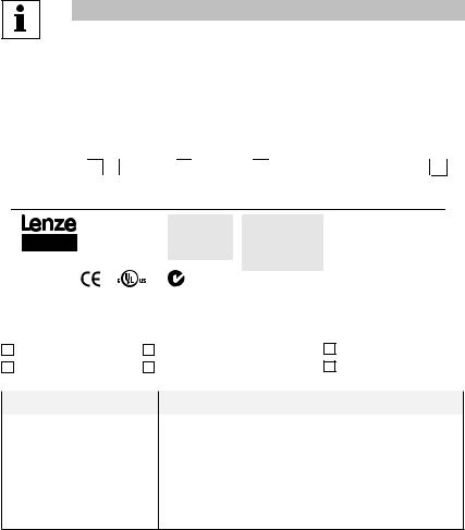
Info zu diesen Anweisungen
Diese Dokumentation gilt für den Frequenzumrichter smd. Sie beinhaltet wichtige technische Daten und beschreibt die Installation, die Inbetriebnahme sowie den Betrieb.
Bitte lesen Sie vor der Inbetriebnahme die Anweisungen.
|
|
|
|
A |
|
B |
|
C |
|
D |
E F |
|||||||
|
|
|
|
Type: |
|
|
|
|
|
|
|
|
+ |
|
|
|||
|
|
|
|
|
Input: 1(2)/N/PE AC |
Output: 3/PE AC |
For detailed information |
|
||||||||||
|
|
|
|
ESMD751X2SFA |
|
230/240 V |
|
0-230 V |
refer to instruction |
|
|
|
|
|
||||
|
|
|
|
|
|
|||||||||||||
|
|
|
|
Id-No: 13XSAPID |
|
9.0 A |
|
4 A |
Manual SX03 |
|
|
|
|
|
||||
|
|
Made in USA |
|
|
|
|
50-60 Hz |
|
0.75 kW / 1HP |
SN: 13XSAPID012345678 |
|
|
|
|
|
|||
|
|
|
|
|
|
|
|
|||||||||||
|
|
|
|
|
|
|
|
|
|
|
0 - 500 Hz |
|
|
|
|
|
|
|
|
|
Inverter |
|
|
LISTED |
|
|
|
|
|
ESMD751X2SFA 000XX |
XX |
|
XX |
|
|||
|
|
|
|
5D81 |
|
|
|
1341308801234567 |
|
|
|
|
|
|
||||
|
|
smd - basic I/O |
|
IND. CONT. EQ. |
N10104 |
|
|
|
|
|
|
|
||||||
|
|
|
|
|
|
|
Z519 |
|
|
|
|
|
|
|
|
|
|
|
|
|
|
|
|
|
|
|
|
|
|
|
|
|
|
|
V0010 |
||
|
|
|
|
|
|
|
|
|
|
|
|
|
|
|
|
|||
|
|
A Approbationen |
|
C Eingangsbemessungsdaten |
E Hardwarestand |
|
|
|
|
|
||||||||
|
|
B Typ |
|
D Ausgangsbemessugsdaten |
F Softwarestand |
|
|
|
|
|
||||||||
|
|
|
|
|
|
|
|
|
|
|
|
|
|
|
|
|
|
|
|
|
Lieferumfang |
|
|
Wichtig |
|
|
|
|
|
|
|
|
|
||||
|
|
|
|
|
|
|
|
|
|
|
|
|
|
|
|
|||
|
|
• 1 Frequenzumrichter smd |
Prüfen Sie unmittelbar nach Erhalt der Lieferung, ob alle gelieferten |
|||||||||||||||
|
|
(ESMD...)mit installiertem EPM |
Objekte den Angaben auf den beiliegenden Unterlagen entsprechen. |
|||||||||||||||
|
|
(siehe Abschnitt 4.2) |
|
|
Lenze haftet nicht für im Nachhinein gemeldete Mängel. |
|
|
|
|
|
||||||||
|
|
• 1 Betriebsanleitung |
|
|
Melden Sie |
|
|
|
|
|
|
|
|
|
||||
•erkennbare Transportschäden umgehend dem
Transportunternehmen.
•erkennbare Mängel/unvollständige Lieferungen umgehend Ihrem
Lenze-Vertreter.
2 |
Lenze 13435747 EDBSX03 v17 EN, DE, FR, IT, ES |
Sicherheitsinformationen
1Sicherheitsinformationen
Allgemeine Informationen
Einige Bauteile in Lenze-Reglern (Frequenzumrichter, Servoumrichter, DC-Steuerungen) können stromführend sein, sich bewegen oder rotieren. Einige Oberflächen können heiß werden.
Unbefugtes Entfernen der erforderlichen Abdeckung, unsachgemäße Verwendung und nicht vorschriftsmäßige Installation oder Bedienung können schwere Personenoder Sachschäden verursachen.
Sämtliche Tätigkeiten bei Transport, Installation und Inbetriebnahme sowie Wartungsarbeiten müssen von qualifiziertem und geschultem Fachpersonal durchgeführt werden (IEC 364 und CENELEC HD 384 oder
DIN VDE 0100 und IEC-Report 664 oder DIN VDE 0110 sowie nationale Unfallverhütungsvorschriften müssen beachtet werden).
Gemäß diesen grundlegenden Sicherheitsinformationen handelt es sich bei qualifiziertem und geschultem
Fachpersonal um Personen, die mit der Installation, der Montage, der Inbetriebnahme und dem Betrieb des Produkts vertraut sind und die über die für ihre Tätigkeit erforderlichen Qualifikationen verfügen.
Anwendung wie vorgeschrieben
Antriebsregler sind Bauteile, die für die Installation in elektrischen Systemen oder Maschinen vorgesehen sind. Sie dürfen nicht als separate Geräte verwendet werden. Sie sind ausschließlich für professionelle und kommerzielle Zwecke gemäß EN 61000-3-2 gedacht. Die Dokumentation enthält Informationen zur Einhaltung der Norm EN 61000-3-2.
Bei der Installation der Antriebsregler in Maschinen ist die Inbetriebnahme (d. h. der Start des Betriebs wie vorgeschrieben) untersagt, bis nachgewiesen wurde, dass die Maschine den Bestimmungen der EG-Richtlinie 2006/42/EG (Maschinenrichtlinie) entspricht und die harmonisierte Norm EN 60204 eingehalten wird.
Die Inbetriebnahme (d. h. der Start des Betriebs wie vorgeschrieben) ist nur dann zulässig, wenn die EMV-Richtlinie 2004/108/EWG eingehalten wird.
Die Antriebsregler genügen den Anforderungen der Niederspannungsrichtlinie 2006/95/EWG. Für die Regler gelten die harmonisierten Normen der Serie EN 50178/DIN VDE 0160.
Hinweis: Die Verfügbarkeit von Reglern ist gemäß Norm EN 61800-3 eingeschränkt. Diese Produkte können in Wohngebieten Funkstörungen verursachen. In diesem Fall sind eventuell besondere Vorkehrungen zu treffen.
Installation
Sorgen Sie für sachgemäßen Umgang und vermeiden Sie übermäßige mechanische Beanspruchung. Vermeiden Sie ein Verbiegen von Bauteilen und das Ändern von Isolationsabständen beim Transport oder dem Umgang mit der Einheit. Berühren Sie keine elektronischen Bauteile und Kontakte.
Regler enthalten elektrostatisch empfindliche Bauteile, die bei unsachgemäßem Umgang leicht beschädigt werden können. Beschädigen oder zerstören Sie keine elektrischen Bauteile, da dadurch Ihre Gesundheit gefährdet werden könnte!
Elektrische Anschlüsse
WennArbeiten an stromführendenAntriebsreglern durchgeführt werden, müssen die geltenden nationalen Unfallverhütungsvorschriften (z. B. VBG 4) eingehalten werden.
Die Elektroinstallation muss im Sinne der geltenden Bestimmungen (z. B. Leitungsquerschnitte, Sicherungen, PE-Anschlüsse) durchgeführt werden. Zusätzliche Informationen können der Dokumentation entnommen werden.
Die Dokumentation enthält Informationen über die Installation gemäß den EMV-Richtlinien (Abschirmung, Erdung, Filter und Leitungen). Diese Hinweise gelten auch für mit dem CE-Zeichen gekennzeichnete Regler.
Der Hersteller des Systems oder der Maschine ist für die Einhaltung der erforderlichen Grenzwerte gemäß den EMV-Richtlinien verantwortlich.
nthält spezielle Informationen über UL.
Lenze 13435747 EDBSX03 v17 EN, DE, FR, IT, ES |
3 |
Sicherheitsinformationen
Betrieb
Systeme mit Reglern müssen mit zusätzlichen Überwachungsund Schutzvorrichtungen ausgerüstet werden, die den geltenden Normen (z. B. Normen für technische Einrichtungen, Unfallverhütungsvorschriften usw.) entsprechen. Der Regler darf wie in der Dokumentation beschrieben für Ihre Anwendung angepasst werden.
GEFAHR!
•Nachdem die Stromversorgung des Reglers unterbrochen wurde, dürfen stromführende Bauteile und Netzverbindungen nicht sofort berührt werden, da Kondensatoren noch geladen sein können. Beachten Sie hierzu die entsprechenden Hinweise auf dem Regler.
•Schalten Sie den Regler nicht öfter als einmal alle drei Minuten ein und wieder aus.
•Schließen Sie beim Betrieb alle Schutzabdeckungen und -türen.
1.1In diesen Anweisungen verwendete Piktogramme
Piktogramm |
Signalwort |
Bedeutung |
Folgen bei Missachtung |
||
|
|
|
|
|
|
|
|
|
GEFAHR! |
Gefar von Personenschäden |
Hinweis auf eine unmittelbar drohende Gefahr, |
|
|
|
|||
|
|
|
|
durch gefährliche elektriche |
die den Tod oder schwere Verletzungen |
|
|
|
|
Spannung |
zur Folge haben kann, wenn nicht die |
|
|
|
|
|
entsprechenden Maßnahmen getroffen werden. |
|
|
|
|
|
|
|
|
|
|
|
|
|
|
|
WARNUNG! |
Mögliche drohende |
Tod oder Verletzungen |
|
|
|
|||
|
|
|
|
Personenschäden |
|
|
|
|
|
|
|
|
|
|
|
|
|
|
|
|
STOP! |
Mögliche Sachschäden |
Schäden am Antriebssystem oder seiner |
|
|
|
|
|
Umgebung |
|
|
|
|
|
|
|
|
|
Hinweis |
Nützlicher Tipp |
Das Befolgen dieser Tipps vereinfacht den |
|
|
|
|||
|
|
|
|
|
Umgang mit dem Antrieb. |
|
|
|
|
|
|
|
|
|
|
|
|
4 |
Lenze 13435747 EDBSX03 v17 EN, DE, FR, IT, ES |
Sicherheitsinformationen
Hinweis für UL-zugelassene Systeme mit integrierten Reglern
UL-Warnungen sind Hinweise, die für UL-Systeme gelten. Die Dokumentation enthält spezielle Informationen über UL.
|
• Die integrierten Halbleiter-Schutzeinrichtungen bieten keinen Schutz für Zweigstromkreise. |
|
|
|
Die Zweigstromkreise müssen gemäß dem National Electrical Code und gemäß jeglicher |
|
|
|
weiterer lokaler Vorschriften gesichert werden. Sicherungen und Leistungsschalter bieten |
|
|
WARNUNG! |
den einzig wirksamen Schutz für Zweigstromkreise. |
|
|
• Bei Absicherung mit Sicherungen der Klassen CC und T für die Verwendung in |
|
||
|
Stromkreisen mit einem maximalen Strom von 200 kAeff (sym.) bei der auf dem Antrieb |
|
|
|
angegebenen maximalen Nennspannung geeignet. |
|
|
|
• Ebenfalls geeignet bei Absicherung mit einem Leistungsschalter, der ein Schaltvermögen |
|
|
|
von mindestens 200 kAeff (sym.) bei der auf dem Antrieb angegebenen maximalen |
|
|
|
Nennspannung aufweist. (außer ESMD113_4T_, ESMD112_2Y_, ESMD113_2T_, |
|
|
|
|
||
|
ESMD152_2Y_, ESMD153_2T_, ESMD222_2Y_, ESMD223_4T_, ESMD402_2T_, |
|
|
|
ESMD552_2T_, ESMD752_2T_, ESMD153_4T_, und ESMD183_4T ausgenommen). |
|
|
|
• Für mindestens 75°C ausgelegte Kupferkabel verwenden, außer für Steuerkreise. |
|
|
|
• Bei Steuerkreisen sind Kabel gemäß NEC Class 1 ausreichend. |
|
|
|
• Die Drehmomentanforderungen sind in Abschnitt 3.2.3, Schaltplan. |
|
|
|
• Vorgesehen für Umgebungen mit Verunreinigungsgrad 2. |
|
|
|
|
|
|
GEFAHR!
Gefahr eines elektrischen Schlages! Kondensatoren sind bis ca. 180 Sekunden nach dem Abschalten der Spannungsversorgung weiterhin geladen. Trennen Sie die Spannungsversorgung, und warten Sie mindestens 3 Minuten, bevor Sie den Antrieb berühren.
WARNUNG!
Wenn die Schutzeinrichtung des Zweigstromkreises ausgelöst hat, deutet dies darauf hin, dass ein Fehlerstrom unterbrochen wurde. Um die Gefahr von Bränden und elektrischem Schlag zu verringern, untersuchen Sie jegliche stromführenden Teile und sonstige Komponenten des Reglers, und tauschen Sie jegliche beschädigten Teile aus.
Lenze 13435747 EDBSX03 v17 EN, DE, FR, IT, ES |
5 |

Technische Daten
2Technische Daten
2.1Normen und Anwendungsbedingungen
|
|
Konformität |
CE |
Niedrigspannungsrichtlinie (2006/95/EWG); (2004/108/EWG) |
|
|
|
Zulassungen |
UL 508C |
Underwriters Laboratories - Power Conversion Equipment |
|
|
|
|
|
|
|
|
|
Max. zulässige Motorleitungslänge |
Geschirmt: |
50 m (niedrige Kapazität) |
|
(1) |
Ungeschirmt: |
100 m |
|||
|
|
|
|||
|
|
|
|
|
|
|
|
Phasenabweichung |
< 2% |
|
|
|
|
Eingangsspannung |
|
|
|
|
|
|
|
|
|
|
|
Feuchtigkeit |
< 95% (ohne Betauung) |
||
|
|
Ausgangsfrequenz |
0...500 Hz |
|
|
|
|
|
|
|
|
|
|
Umgebungsbedingungen |
Klasse 3K3 nach EN 50178 |
||
|
|||||
|
|
|
|
|
|
|
|
|
Transport |
|
-25 … +70 °C |
|
|
|
|
|
|
|
|
Temperaturbereich |
Lagerung |
|
-20 … +70 °C |
|
|
|
|
|
|
|
|
|
Betrieb |
|
0 … +55 °C (über +40 °C Ausgangsbemessungsstrom um |
|
|
|
|
2,5 %/°C |
|
|
|
|
|
|
|
|
|
Installationshöhe |
0 … 4000 m üNN (über 1000 m üNN Ausgangsbemessungsstrom um 5 |
||
|
|
%/1000 m reduzieren) |
|||
|
|
|
|||
|
|
Vibrationsfestigkeit |
Beschleunigungsfest bis 0,7 g 10... 150Hz |
||
|
|
|
|
||
|
|
Ableitstrom |
> 3,5 mA gegen PE |
||
Schutzart durch Gehäuse (EN 60529) IP 20
Schutzmaßnahmen gegen |
Kurzschluss, Erdschluss, Überspannung, Abwürgen des Motors, Überlastung |
||
des Motors |
|
||
|
|
||
|
|
|
|
|
Gesamtleistung |
|
|
Betrieb am öffentlichen |
an Hauptver- |
Einhaltung der Anforderungen (2) |
|
sorgung |
|
||
Versorgungsnetz |
|
|
|
(Einschränkung harmonischer |
< 0,5 kW |
mit Netzdrossel |
|
Ströme gemäß EN 61000-3-2) |
|
|
|
0,5 … 1 kW |
mit aktivem Filter (in Vorbereitung) |
||
|
|||
|
> 1 kW |
ohne zusätzliche Maßnahmen |
|
|
|
|
|
Supply Conditions |
AC Mains |
Direct Connection |
|
|
|
|
|
|
TT |
For central grounded systems operation is permitted without |
|
|
restrictions |
||
|
|
||
|
|
For corner grounded 400/500V systems, operation is |
|
Power System |
TN |
possible, but reinforced insulation to control circuits is |
|
|
|
compromised. |
|
|
IT Mains |
IT Mains power systems are not supported |
|
|
|
|
|
(1)Zur Einhaltung der EMV-Richtlinien können die zulässigen Leitungslängen geändert werden.
(2)Die beschriebenen zusätzlichen Maßnahmen stellen lediglich sicher, dass die Regler den Anforderungen gemäß EN 61000-3-2 entsprechen. Der Hersteller der Maschine/des Systems ist verantwortlich für die Einhaltung der für die Maschine/das System geltenden Anforderungen!
6 |
Lenze 13435747 EDBSX03 v17 EN, DE, FR, IT, ES |

Technische Daten
2.2Bemessungsdaten
Typ |
Leis- |
|
Netz |
|
|
|
Ausgangsstrom |
|
|
|
|
|
tung |
Spannung, Frequenz |
Strom |
Ir |
|
Imax für 60 s |
|
|
|||
|
[kW] |
|
|
[A] |
|
|
|
|
|
|
|
|
|
|
[A](1) |
|
[A](2) |
[A](1) |
[A](2) |
|
|
||
|
|
|
|
|
|
|
|||||
ESMD251X2SFA |
0,25 |
|
|
3,4 |
1,7 |
|
1,6 |
2,6 |
2,4 |
|
|
|
|
|
|
|
|
|
|
|
|
|
|
ESMD371X2SFA |
0,37 |
1/N/PE |
230/240 V |
5,0 |
2,4 |
|
2,2 |
3,6 |
3,3 |
|
|
|
|
|
|
|
|
|
|
|
|
||
ESMD551X2SFA |
0,55 |
6,0 |
3,0 |
|
2,8 |
4,5 |
4,2 |
|
|
||
2/PE |
230/240 V |
|
|
|
|||||||
|
|
(180 V - 0% … 264 V + 0 %) |
|
|
|
|
|
|
|
|
|
ESMD751X2SFA |
0,75 |
9,0 |
4,0 |
|
3,7 |
6,0 |
5,5 |
|
|
||
50/60 Hz |
|
|
|
||||||||
|
|
(48 Hz - 0 % … 62 Hz + 0 %) |
|
|
|
|
|
|
|
|
|
ESMD152X2SFA |
1,5 |
14,0 |
7,0 |
|
6,4 |
10,5 |
9,6 |
|
|
||
|
|
|
|
|
|||||||
|
|
|
|
|
|
|
|
|
|
|
|
ESMD222X2SFA |
2,2 |
|
|
21,0 |
9,5 |
|
8,7 |
14,3 |
13,1 |
|
|
|
|
|
|
|
|
|
|
|
|
|
|
ESMD371X2TXA |
0,37 |
|
|
2,7 |
2,4 |
|
2,2 |
3,6 |
3,3 |
|
|
|
|
|
|
|
|
|
|
|
|
|
|
ESMD751X2TXA |
0,75 |
|
|
5,1 |
4,2 |
|
3,9 |
6,3 |
5,9 |
|
|
|
|
|
|
|
|
|
|
|
|
|
|
ESMD112X2TXA |
1,1 |
3/PE |
230/240 V |
6,9 |
6,0 |
|
5,5 |
9,0 |
8,3 |
|
|
|
|
|
|
|
|
|
|
|
|
||
ESMD152X2TXA |
1,5 |
(180 V - 0% … 264 V + 0 %) |
7,9 |
7,0 |
|
6,4 |
10,5 |
9,6 |
|
|
|
50/60 Hz |
|
|
|
||||||||
|
|
|
|
|
|
|
|
|
|
||
ESMD222X2TXA |
2,2 |
(48 Hz - 0 % … 62 Hz + 0 %) |
11,0 |
9,6 |
|
8,8 |
14,4 |
13,2 |
|
|
|
|
|
|
|
|
|||||||
|
|
|
|
|
|
|
|
|
|
|
|
ESMD302X2TXA |
3,0 |
|
|
13,5 |
12,0 |
|
11,0 |
18,0 |
16,5 |
|
|
|
|
|
|
|
|
|
|
|
|
|
|
ESMD402X2TXA |
4,0 |
|
|
17,1 |
15,2 |
|
14,0 |
22,8 |
21,0 |
|
|
|
|
|
|
|
|
|
|
|
|
|
|
(1)Bei Netzbemessungsspannung und Schaltfrequenz 4, 6, 8 kHz
(2)Bei Netzbemessungsspannung und Schaltfrequenz 10 kHz
Lenze 13435747 EDBSX03 v17 EN, DE, FR, IT, ES |
7 |
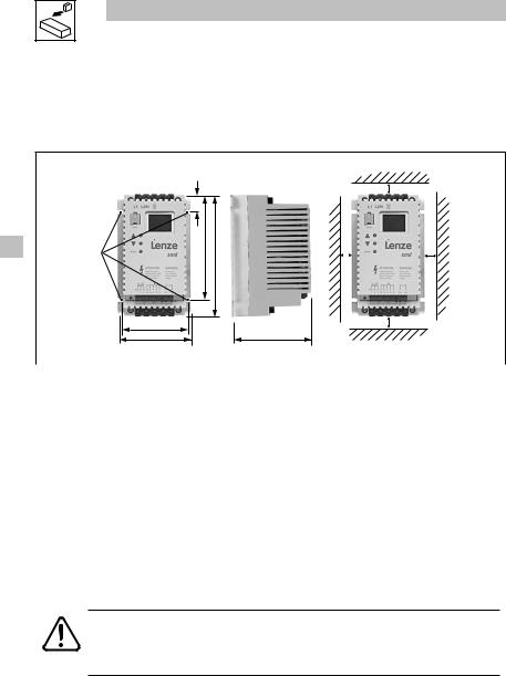
Installation
3Installation
3.1Mechanische Installation
3.1.1Abmessungen und Montage
4 x M4
2,4 Nm
21 lb-in
|
|
>50 |
|
b2 |
|
|
>15 |
>15 |
|
b1 b |
|
a1 |
|
>50 |
a |
c |
|
smd002
Typ |
a [mm] |
a1 [mm] |
b [mm] |
b1 [mm] |
b2 [mm] |
c [mm] |
m [kg] |
|
ESMD251X2SFA |
93 |
84 |
146 |
128 |
17 |
83 |
0.5 |
|
|
||||||||
ESMD371X2SFA |
||||||||
|
|
|
|
|
|
|
||
|
|
|
|
|
|
|
|
|
ESMD551X2SFA |
93 |
84 |
146 |
128 |
17 |
92 |
0.6 |
|
|
||||||||
ESMD751X2SFA |
||||||||
|
|
|
|
|
|
|
||
|
|
|
|
|
|
|
|
|
ESMD152X2SFA |
114 |
105 |
146 |
128 |
17 |
124 |
1.2 |
|
|
|
|
|
|
|
|
|
|
ESMD222X2SFA |
114 |
105 |
146 |
128 |
17 |
140 |
1.4 |
|
|
|
|
|
|
|
|
|
|
ESMD371X2TXA |
93 |
84 |
146 |
128 |
17 |
83 |
0.5 |
|
|
|
|
|
|
|
|
|
|
ESMD751X2TXA |
93 |
84 |
146 |
128 |
17 |
92 |
0.6 |
|
|
|
|
|
|
|
|
|
|
ESMD112X2TXA |
93 |
84 |
146 |
128 |
17 |
141 |
1.2 |
|
|
||||||||
ESMD152X2TXA |
||||||||
|
|
|
|
|
|
|
||
|
|
|
|
|
|
|
|
|
ESMD222X2TXA |
114 |
105 |
146 |
128 |
17 |
140 |
1.4 |
|
|
|
|
|
|
|
|
|
|
ESMD302X2TXA |
114 |
105 |
146 |
128 |
17 |
171 |
1.9 |
|
|
|
|
|
|
|
|
|
|
ESMD402X2TXA |
114 |
105 |
146 |
100 |
17 |
171 |
1.7 |
WARNUNG!
Die Antriebe dürfen nicht an Orten installiert werden, an denen sie ungünstigen Umgebungsbedingungen ausgesetzt sind. Hierzu gehören: brennbare, ölige oder schädliche Dämpfe oder Staub; übermäßige Feuchtigkeit; extreme Vibrationen oder Temperaturen. Für zusätzliche Informationen wenden Sie sich bitte direkt an Lenze.
8 |
Lenze 13435747 EDBSX03 v17 EN, DE, FR, IT, ES |
 Loading...