


 Loading...
EDKVS93−01
.MñP
Ä.MñPä
Information for the operator of the machine
9300 0.37 ... 11 kW
EVS9321−xx ... EVS9326−xx
Servo controller
l

9300std078
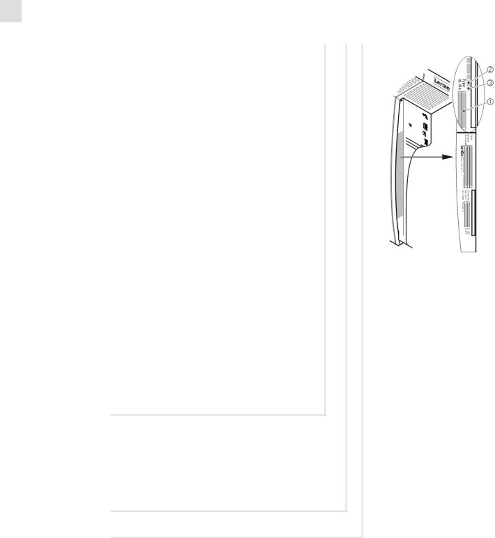
Key for overview
Position Description
0Controller
1Fixing rails for standard mounting
2Cover for the motor connection
3Shield connection support with fixing screws (2 items)
1 support for the shield sheet for the supply connections 1 support for the shield sheet for the motor cable
4EMC shield sheet with fixing screws (2 items)
1 shield sheet for the supply connections
1 shield sheet for the motor cable and the feed cable for the motor temperature monitoring with PTC thermistor or thermal contact (NC contact)
5EMC shield sheet with fixing screws for shielded control cables
6Cover for the supply connections
Connections and interfaces
Position |
Description |
|
L1, L2, L3, PE |
Mains connection |
|
|
|
|
+UG, −UG |
DC supply |
|
|
|
|
U, V, W, PE |
Motor connection |
|
|
|
|
T1, T2 |
Connection of PTC thermistor or thermal contact (NC contact) of the motor |
|
|
|
|
X1 |
AIF interface (automation interface) |
|
|
Slot for communication module (e. g. XT EMZ9371BC keypad) |
|
|
|
|
X3 |
Jumper for setting analog input signal at X6/1, X6/2 |
|
|
|
|
X4 |
System bus (CAN) connection |
|
|
|
|
X5 |
Connection of digital inputs and outputs |
|
|
|
|
X6 |
Connection of analog inputs and outputs |
|
|
|
|
X7 |
Connection of resolver and KTY temperature sensor of the motor |
|
|
|
|
X8 |
Connection of incremental encoder with TTL level or SinCos encoder and KTY temperature sensor of the motor |
|
|
|
|
X9 |
Connection of digital frequency input signal |
|
|
|
|
X10 |
Connection of digital frequency output signal |
|
|
|
|
X11 |
Connection of KSR relay output for "safe standstill" (for variants V004 and V104 only) |
|
Status displays
Position |
LED red |
LED green |
Operating status |
|
|
|
|
|
|
• |
Off |
On |
Controller enabled |
|
|
|
|
|
|
|
On |
On |
Mains is switched on and automatic start is inhibited |
|
|
|
|
|
|
|
Off |
Blinking slowly |
Controller inhibited |
|
|
|
|
|
|
|
Blinking quickly |
Off |
Undervoltage or overvoltage |
|
|
|
|
|
|
|
Blinking slowly |
Off |
Active fault |
|

i Contents
1 |
About this documentation . . . . . . . . . . . . . . . . . . . . . . . . . . . . . . . . . . . . . . . . . . . . . . . . . . |
5 |
||
|
1.1 |
Document history . . . . . . . . . . . . . . . . . . . . . . . . . . . . . . . . . . . . . . . . . . . . . . . . . . . . |
5 |
|
|
1.2 |
Target group . . . . . . . . . . . . . . . . . . . . . . . . . . . . . . . . . . . . . . . . . . . . . . . . . . . . . . . . |
5 |
|
|
1.3 |
Validity information . . . . . . . . . . . . . . . . . . . . . . . . . . . . . . . . . . . . . . . . . . . . . . . . . . |
6 |
|
|
1.4 |
Conventions used . . . . . . . . . . . . . . . . . . . . . . . . . . . . . . . . . . . . . . . . . . . . . . . . . . . . |
7 |
|
|
1.5 |
Notes used . . . . . . . . . . . . . . . . . . . . . . . . . . . . . . . . . . . . . . . . . . . . . . . . . . . . . . . . . . |
8 |
|
2 |
Safety instructions . . . . . . . . . . . . . . . . . . . . . . . . . . . . . . . . . . . . . . . . . . . . . . . . . . . . . . . . . |
9 |
||
|
2.1 |
General safety and application notes for Lenze controllers . . . . . . . . . . . . . . . . . . |
9 |
|
|
2.2 |
Thermal motor monitoring . . . . . . . . . . . . . . . . . . . . . . . . . . . . . . . . . . . . . . . . . . . . |
13 |
|
|
|
2.2.1 |
Forced ventilated or naturally ventilated motors . . . . . . . . . . . . . . . . . . . |
14 |
|
|
2.2.2 |
Self−ventilated motors . . . . . . . . . . . . . . . . . . . . . . . . . . . . . . . . . . . . . . . . . |
15 |
|
2.3 |
Residual hazards . . . . . . . . . . . . . . . . . . . . . . . . . . . . . . . . . . . . . . . . . . . . . . . . . . . . . |
17 |
|
|
2.4 |
Safety instructions for the installation according to UL . . . . . . . . . . . . . . . . . . . . . |
18 |
|
3 |
Parameter setting . . . . . . . . . . . . . . . . . . . . . . . . . . . . . . . . . . . . . . . . . . . . . . . . . . . . . . . . . |
19 |
||
|
3.1 |
Parameter setting with the XT EMZ9371BC keypad . . . . . . . . . . . . . . . . . . . . . . . . |
19 |
|
|
|
3.1.1 |
General data and operating conditions . . . . . . . . . . . . . . . . . . . . . . . . . . |
19 |
|
|
3.1.2 |
Installation and commissioning . . . . . . . . . . . . . . . . . . . . . . . . . . . . . . . . |
20 |
|
|
3.1.3 |
Display elements and function keys . . . . . . . . . . . . . . . . . . . . . . . . . . . . . |
21 |
|
|
3.1.4 |
Changing and saving parameters . . . . . . . . . . . . . . . . . . . . . . . . . . . . . . . |
23 |
|
|
3.1.5 |
Loading a parameter set . . . . . . . . . . . . . . . . . . . . . . . . . . . . . . . . . . . . . . . |
25 |
|
|
3.1.6 |
Transferring parameters to other standard devices . . . . . . . . . . . . . . . . . |
26 |
|
|
3.1.7 |
Activating password protection . . . . . . . . . . . . . . . . . . . . . . . . . . . . . . . . . |
28 |
|
|
3.1.8 |
Diagnostics . . . . . . . . . . . . . . . . . . . . . . . . . . . . . . . . . . . . . . . . . . . . . . . . . . |
29 |
|
|
3.1.9 |
Menu structure . . . . . . . . . . . . . . . . . . . . . . . . . . . . . . . . . . . . . . . . . . . . . . |
30 |
4 |
Troubleshooting and fault elimination . . . . . . . . . . . . . . . . . . . . . . . . . . . . . . . . . . . . . . . |
32 |
||
|
4.1 |
Display of operating data, diagnostics . . . . . . . . . . . . . . . . . . . . . . . . . . . . . . . . . . . |
32 |
|
|
4.2 |
Troubleshooting . . . . . . . . . . . . . . . . . . . . . . . . . . . . . . . . . . . . . . . . . . . . . . . . . . . . . |
33 |
|
|
|
4.2.1 |
Status display via controller LEDs . . . . . . . . . . . . . . . . . . . . . . . . . . . . . . . . |
33 |
|
|
4.2.2 |
Fault analysis with the history buffer . . . . . . . . . . . . . . . . . . . . . . . . . . . . |
34 |
|
|
4.2.3 |
Fault analysis via LECOM status words (C0150/C0155) . . . . . . . . . . . . . |
35 |
|
4.3 |
System error messages . . . . . . . . . . . . . . . . . . . . . . . . . . . . . . . . . . . . . . . . . . . . . . . . |
36 |
|
|
|
4.3.1 |
General error messages . . . . . . . . . . . . . . . . . . . . . . . . . . . . . . . . . . . . . . . . |
36 |
|
|
4.3.2 |
Resetting system error messages . . . . . . . . . . . . . . . . . . . . . . . . . . . . . . . . |
45 |
4 |
l |
EDKVS93−01 EN 3.0

About this documentation |
1 |
Document history
1 |
About this documentation |
)Note!
This documentation contains all necessary information for the machine operator to be able to operate the servo controllers of the 9300 series installed in your machine/plant.
You can make further use of all information in this documentation without consulting Lenze if you do not make any changes to the contents.
1.1Document history
What is new / what has changed?
Material number |
Version |
|
|
Description |
|
.MñP |
3.0 |
07/2013 |
TD06 |
Error corrections |
|
|
|
|
|
|
|
13330541 |
2.1 |
03/2010 |
TD23 |
Change of the company’s address |
|
|
|
|
|
|
|
13330541 |
2.0 |
03/2010 |
TD14 |
New edition due to reorganisation of the company |
|
|
|
|
|
UL−warnings updated |
|
|
|
|
|
Revision for software version 8x |
|
|
|
|
|
|
|
13231631 |
1.0 |
11/2007 |
TD34 |
First edition |
|
I Tip!
Information and auxiliary devices related to the Lenze products can be found in the download area at
http://www.Lenze.com
1.2Target group
This documentation is directed at qualified skilled personnel according to IEC 60364.
Qualified skilled personnel are persons who have the required qualifications to carry out all activities involved in installing, mounting, commissioning, and operating the product.
EDKVS93−01 EN 3.0
l 5
1 |
About this documentation |
|
Validity information |
|
|
1.3Validity information
... 9300 servo controllers as of nameplate data:
|
|
|
|
|
• |
‚ |
ƒ |
Nameplate |
|||
|
|
EVS 93xx |
˘ x |
x |
Vxxx 1x |
8x |
|
||||
|
|
|
|||||||||
Product series |
|
|
|
|
|
|
|
|
|
|
|
EVS = |
Servo controller |
|
|
|
|
|
|
||||
Type no. / rated power |
|
|
|
|
|
|
|||||
|
|
|
|
|
|
|
|
|
|||
|
400 V |
480 V |
|
|
|
|
|
||||
9321 = |
0.37 kW |
0.37 kW |
|
|
|
|
|
||||
9322 = |
0.75 kW |
0.75 kW |
|
|
|
|
|
||||
9323 = |
1.5 kW |
1.5 kW |
|
|
|
|
|
||||
9324 = |
3.0 kW |
3.0 kW |
|
|
|
|
|
||||
9325 = |
5.5 kW |
5.5 kW |
|
|
|
|
|
||||
9326 = |
11 kW |
11 kW |
|
|
|
|
|
||||
Type |
|
|
|
|
|
|
|
|
|
|
|
|
|
|
|
|
|
|
|||||
E = |
Panel−mounted unit |
|
|
|
|
||||||
C = |
Built−in unit in "cold plate" technique |
|
|
|
9300vec112 |
||||||
|
|
|
|
||||||||
Design |
|
|
|
|
|
|
|
|
|
|
|
|
|
|
|
|
|
|
|
|
|
|
|
I = |
Servo PLC |
|
|
|
|
|
|
|
|
|
|
K = |
Servo cam |
|
|
|
|
|
|
|
|
|
|
P = |
Servo position controller |
|
|
|
|||||||
R = |
Register controller |
|
|
|
|||||||
S = |
Servo inverter |
|
|
|
|||||||
T = |
Servo PLC technology |
|
|
|
|||||||
Variant
˘Standard
V003 = In "cold plate" technique
V004 = With "safe standstill" function
V100 = For IT mains
V104 = With "safe standstill" function and for IT mains
Hardware version
Software version
6 |
l |
EDKVS93−01 EN 3.0

About this documentation |
1 |
Conventions used
1.4Conventions used
This documentation uses the following conventions to distinguish between different types of information:
Type of information |
Identification |
Examples/notes |
|
|
Spelling of numbers |
|
|
|
|
|
|
|
|
|
|
Decimal separator |
language−dependen |
In each case, the signs typical for the target |
|
|
|
t |
language are used as decimal separators. |
|
|
|
|
For example: 1234.56 or 1234,56 |
|
|
|
|
|
|
Warnings |
|
|
|
|
UL warnings
UR warnings
Text
J
Are only given in English.
O
|
Program name |
» « |
PC software |
|
|
|
For example: »Engineer«, »Global Drive |
|
|
|
Control« (GDC) |
|
|
|
|
Icons |
|
|
|
|
|
|
|
|
Page reference |
^ |
Reference to another page with additional |
|
|
|
information |
|
|
|
For instance: ^16 = see page 16 |
|
|
|
|
|
Documentation reference |
, |
Reference to another documentation with |
|
|
|
additional information |
|
|
|
For example: ,EDKxxx = see |
|
|
|
documentation EDKxxx |
EDKVS93−01 EN 3.0
l 7

1 |
About this documentation |
|
Notes used |
|
|
1.5Notes used
The following pictographs and signal words are used in this documentation to indicate dangers and important information:
Safety instructions
Structure of safety instructions:
} Danger!
(characterises the type and severity of danger)
Note
(describes the danger and gives information about how to prevent dangerous situations)
Pictograph and signal word |
Meaning |
|
{ Danger! |
Danger of personal injury through dangerous electrical voltage. |
|
Reference to an imminent danger that may result in death or |
|
|
serious personal injury if the corresponding measures are not |
|
|
|
taken. |
|
|
|
|
} Danger! |
Danger of personal injury through a general source of danger. |
|
Reference to an imminent danger that may result in death or |
|
|
serious personal injury if the corresponding measures are not |
|
|
|
taken. |
|
|
|
|
( Stop! |
Danger of property damage. |
|
Reference to a possible danger that may result in property |
|
|
damage if the corresponding measures are not taken. |
|
|
|
|
|
Application notes |
|
|
|
|
|
Pictograph and signal word |
Meaning |
|
) Note! |
Important note to ensure troublefree operation |
|
|
|
|
|
|
|
I Tip! |
Useful tip for simple handling |
|
|
|
|
|
|
|
, |
Reference to another documentation |
|
|
|
|
|
|
|
Special safety instructions and application notes for UL and UR |
|
|
|
|
|
Pictograph and signal word |
Meaning |
|
J Warnings! |
Safety or application note for the operation of a UL−approved |
|
device in UL−approved systems. |
|
|
Possibly the drive system is not operated in compliance with UL |
|
|
|
if the corresponding measures are not taken. |
|
|
|
|
O Warnings! |
Safety or application note for the operation of a UR−approved |
|
device in UL−approved systems. |
|
|
Possibly the drive system is not operated in compliance with UL |
|
|
|
if the corresponding measures are not taken. |
|
8 |
l |
EDKVS93−01 EN 3.0

Safety instructions |
2 |
General safety and application notes for Lenze controllers
2 |
Safety instructions |
2.1General safety and application notes for Lenze controllers
(in accordance with Low−Voltage Directive 2006/95/EC)
For your personal safety
Disregarding the following safety measures can lead to severe injury to persons and damage to material assets:
ƒOnly use the product as directed.
ƒNever commission the product in the event of visible damage.
ƒNever commission the product before assembly has been completed.
ƒDo not carry out any technical changes on the product.
ƒOnly use the accessories approved for the product.
ƒOnly use original spare parts from Lenze.
ƒObserve all regulations for the prevention of accidents, directives and laws applicable on site.
ƒTransport, installation, commissioning and maintenance work must only be carried out by qualified personnel.
–Observe IEC 364 and CENELEC HD 384 or DIN VDE 0100 and IEC report 664 or DIN VDE 0110 and all national regulations for the prevention of accidents.
–According to this basic safety information, qualified, skilled personnel are persons who are familiar with the assembly, installation, commissioning, and operation of the product and who have the qualifications necessary for their occupation.
ƒObserve all specifications in this documentation.
–This is the condition for safe and trouble−free operation and the achievement of the specified product features.
–The procedural notes and circuit details described in this documentation are only proposals. It is up to the user to check whether they can be transferred to the particular applications. Lenze Automation GmbH does not accept any liability for the suitability of the procedures and circuit proposals described.
ƒDepending on their degree of protection, some parts of the Lenze controllers (frequency inverters, servo inverters, DC speed controllers) and their accessory components can be live, moving and rotating during operation. Surfaces can be hot.
–Non−authorised removal of the required cover, inappropriate use, incorrect installation or operation, creates the risk of severe injury to persons or damage to material assets.
–For more information, please see the documentation.
ƒHigh amounts of energy are produced in the controller. Therefore it is required to wear personal protective equipment (body protection, headgear, eye protection, ear protection, hand guard).
EDKVS93−01 EN 3.0
l 9

2 |
Safety instructions |
|
General safety and application notes for Lenze controllers |
|
|
Application as directed
Controllers are components which are designed for installation in electrical systems or machines. They are not to be used as domestic appliances, but only for industrial purposes according to EN 61000−3−2.
When controllers are installed into machines, commissioning (i.e. starting of the operation as directed) is prohibited until it is proven that the machine complies with the regulations of the EC Directive 2006/42/EC (Machinery Directive); EN 60204 must be observed.
Commissioning (i.e. starting of the operation as directed) is only allowed when there is compliance with the EMC Directive (2004/108/EC).
The controllers meet the requirements of the Low−Voltage Directive 2006/95/EC. The harmonised standard EN 61800−5−1 applies to the controllers.
The technical data and supply conditions can be obtained from the nameplate and the documentation. They must be strictly observed.
Warning: Controllers are products which can be installed in drive systems of category C2 according to EN 61800−3. These products can cause radio interferences in residential areas. In this case, special measures can be necessary.
Transport, storage
Please observe the notes on transport, storage, and appropriate handling.
Observe the climatic conditions according to the technical data.
Installation
The controllers must be installed and cooled according to the instructions given in the corresponding documentation.
The ambient air must not exceed degree of pollution 2 according to EN 61800−5−1.
Ensure proper handling and avoid excessive mechanical stress. Do not bend any components and do not change any insulation distances during transport or handling. Do not touch any electronic components and contacts.
Controllers contain electrostatic sensitive devices which can easily be damaged by inappropriate handling. Do not damage or destroy any electrical components since this might endanger your health!
10 |
l |
EDKVS93−01 EN 3.0
Safety instructions |
2 |
General safety and application notes for Lenze controllers
Electrical connection
When working on live controllers, observe the applicable national regulations for the prevention of accidents (e.g. VBG 4).
The electrical installation must be carried out according to the appropriate regulations (e.g. cable cross−sections, fuses, PE connection). Additional information can be obtained from the documentation.
This documentation contains information on installation in compliance with EMC (shielding, earthing, filter, and cables). These notes must also be observed for CE−marked controllers. The manufacturer of the system is responsible for compliance with the limit values demanded by EMC legislation. The controllers must be installed in housings (e.g. control cabinets) to meet the limit values for radio interferences valid at the site of installation. The housings must enable an EMC−compliant installation. Observe in particular that e.g. the control cabinet doors have a circumferential metal connection to the housing. Reduce housing openings and cutouts to a minimum.
Lenze controllers may cause a DC current in the PE conductor. If a residual current device (RCD) is used for protection against direct or indirect contact for a controller with three−phase supply, only a residual current device (RCD) of type B is permissible on the supply side of the controller. If the controller has a single−phase supply, a residual current device (RCD) of type A is also permissible. Apart from using a residual current device (RCD), other protective measures can be taken as well, e.g. electrical isolation by double or reinforced insulation or isolation from the supply system by means of a transformer.
Operation
If necessary, systems including controllers must be equipped with additional monitoring and protection devices according to the valid safety regulations (e.g. law on technical equipment, regulations for the prevention of accidents). The controllers can be adapted to your application. Please observe the corresponding information given in the documentation.
After the controller has been disconnected from the supply voltage, all live components and power terminals must not be touched immediately because capacitors can still be charged. Please observe the corresponding stickers on the controller.
All protection covers and doors must be shut during operation.
Notes for UL−approved systems with integrated controllers: UL warnings are notes that only apply to UL systems. The documentation contains special UL notes.
Safety functions
Certain controller versions support safety functions (e.g. "Safe torque off", formerly "Safe standstill") according to the requirements of the EC Directive 2006/42/EC (Machinery Directive). The notes on the integrated safety system provided in this documentation must be observed.
Maintenance and servicing
The controllers do not require any maintenance if the prescribed operating conditions are observed.
EDKVS93−01 EN 3.0
l |
11 |

2 |
Safety instructions |
|
General safety and application notes for Lenze controllers |
|
|
Disposal
Recycle metal and plastic materials. Ensure professional disposal of assembled PCBs.
The product−specific safety and application notes given in these instructions must be observed!
12 |
l |
EDKVS93−01 EN 3.0

Safety instructions |
2 |
Thermal motor monitoring
2.2Thermal motor monitoring
From software version 8.0 onwards, the 9300 controllers are provided with an I2xt function for sensorless thermal monitoring of the connected motor.
)Note!
ƒI2 x t monitoring is based on a mathematical model which calculates a thermal motor load from the detected motor currents.
ƒThe calculated motor load is saved when the mains is switched.
ƒThe function is UL−certified, i.e. no additional protective measures are required for the motor in UL−approved systems.
ƒHowever, I2 x t monitoring is no full motor protection as other influences on the motor load could not be detected as for instance changed cooling conditions (e.g. interrupted or too warm cooling air flow).
Die I2 x t load of the motor is displayed in C0066.
The thermal loading capacity of the motor is expressed by the thermal motor time constant (t, C0128). Find the value in the rated motor data or contact the manufacturer of the motor.
The I2 x t monitoring has been designed such that it will be activated after 179 s in the event of a motor with a thermal motor time constant of 5 minutes (Lenze setting C0128), a motor current of 1.5 x IN and a trigger threshold of 100 %.
Two adjustable trigger thresholds provide for different responses.
ƒAdjustable response OC8 (TRIP, warning, off).
–The trigger threshold is set in C0127.
–The response is set in C0606.
–The response OC8, for instance, can be used for an advance warning.
ƒFixed response OC6−TRIP.
–The trigger threshold is set in C0120.
Behaviour of the I2 x t monitoring |
Condition |
|
The I2 x t monitoring is deactivated. |
When C0120 = 0 % and C0127 = 0 %, set controller |
|
C0066 is set = 0 % and |
inhibit. |
|
MCTRL−LOAD−I2XT is set = 0.00 %. |
|
|
|
|
|
I2 x t monitoring is stopped. |
When C0120 = 0 % and C0127 = 0 %, set controller |
|
The current value in C0066 and at the |
enable. |
|
MCTRL−LOAD−I2XT output is frozen. |
|
|
|
|
|
I2 x t monitoring is deactivated. |
Set C0606 = 3 (off) and C0127 > 0 %. |
|
The motor load is displayed in C0066. |
|
|
)Note!
An error message OC6 or OC8 can only be reset if the I2 x t load falls below the set trigger threshold by 5 %.
EDKVS93−01 EN 3.0
l |
13 |
2 |
Safety instructions |
Thermal motor monitoring
Forced ventilated or naturally ventilated motors
2.2.1Forced ventilated or naturally ventilated motors
Parameter setting
The following codes can be set for I2 x t monitoring:
Code |
Meaning |
Value range |
Lenze setting |
|
C0066 |
Display of the I2 x t load of the motor |
0 ... 250 % |
− |
|
C0120 |
Threshold: Triggering of error "OC6" |
0 ... 120 % |
0 % |
|
|
|
|
|
|
C0127 |
Threshold: Triggering of error "OC8" |
0 ... 120 % |
0 % |
|
|
|
|
|
|
C0128 |
Thermal motor time constant |
0.1 ... 50.0 min |
5.0 min |
|
|
|
|
|
|
C0606 |
Response to error "OC8" |
TRIP, warning, off |
Warning |
|
Calculate release time and I2 x t load
Formula for release time |
|
|
|
|
|
Information |
|
|||||||
|
|
|
|
|
|
|
|
|
|
|
IMot |
Actual motor current (C0054) |
|
|
|
|
|
|
|
|
z ) 1 |
I |
Rated motor current (C0088) |
|
|||||
t + * ( t ) |
ln 1 * |
|
|
|
r |
|
|
|||||||
|
|
|
|
|
IMot |
|
2 |
|
|
t |
Thermal motor time constant (C0128) |
|
||
|
|
|
|
|
|
100 |
|
|
|
|||||
|
|
|
IN |
|
|
|
|
|||||||
|
|
|
|
z |
Threshold value in C0120 (OC6) or C0127 (OC8) |
|
||||||||
|
|
|
|
|
|
|
|
|
|
|||||
Formulae for I2 x t load |
|
|
|
|
|
Information |
|
|||||||
|
|
|
|
|
|
|
|
|
|
|
|
L(t) |
Chronological sequence of the I2 x t load of the motor |
|
|
|
|
|
|
|
|
|
|
|
|
|
|
(Display: C0066) |
|
L(t) + |
IMot |
|
2 |
|
|
|
1 |
|
|
|
|
|
|
|
|
|
|
|
*t |
IMot |
Actual motor current (C0054) |
|
|||||||
|
|
|
|
|
|
|||||||||
|
|
100% |
* e t |
|
|
|
||||||||
IN |
|
|
|
|
||||||||||
|
Ir |
Rated motor current (C0088) |
|
|||||||||||
tThermal motor time constant (C0128)
If the controller is inhibited, the I2 x t load is reduced:
|
|
|
LStart |
I2 x t load before controller inhibit |
|
t |
|||
L(t) + LStart e* t |
|
If an error is triggered, the value corresponds to the |
||
|
|
|
|
threshold value set in C0120 (OC6) or C0127 (OC8). |
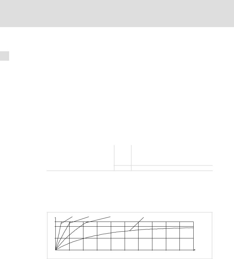
Read release time in the diagram
Diagram for detecting the release times for a motor with a thermal motor time constant of 5 minutes (Lenze setting C0128):
L [%] |
IMot = 3 × IN |
IMot = 2 × IN |
IMot = 1.5 × IN |
|
IMot = 1 × IN |
|
|
|
||
120 |
|
|
|
|
|
|
|
|
|
|
100 |
|
|
|
|
|
|
|
|
|
|
50 |
|
|
|
|
|
|
|
|
|
|
0 |
|
|
|
|
|
|
|
|
|
t [s] |
0 |
100 |
200 |
300 |
400 |
500 |
600 |
700 |
800 |
900 |
1000 |
|
|
|
|
|
|
|
|
|
|
9300STD105 |
Fig. 2−1 I2 × t−monitoring: Release times for different motor currents and trigger thresholds
IMot |
Actual motor current (C0054) |
Ir |
Rated motor current (C0088) |
L |
I2 x t load of the motor (display: C0066) |
TTime
14 |
l |
EDKVS93−01 EN 3.0
Loading...