


 Loading...
L
Manual
Global Drive
System bus (CAN)
for Lenze PLC devices
This documentation is valid for the following Lenze PLC devices:
Automation system |
Type designation |
As of hardware version |
As of software version |
|
|
|
|
9300 Servo PLC |
EVS93XX−xI |
2K |
2.0 |
|
|
|
|
9300 Servo PLC |
EVS93XX−xT |
2K |
2.0 |
|
|
|
|
Drive PLC |
EPL10200 |
Px |
2.0 |
|
|
|
|
ECSxA |
ECSxAxxx |
1A |
6.0 |
|
|
|
|
Important note:
The software is supplied to the user as described in this document. Any risks resulting from its quality or use remain the responsibility of the user. The user must provide all safety measures protecting against possible maloperation.
We do not take any liability for direct or indirect damage, e.g. profit loss, order loss or any loss regarding business.
E2006 Lenze Drive Systems GmbH
No part of this documentation may be copied or made available to third parties without the explicit written approval of Lenze Drive Systems GmbH.
All information given in these Operating Instructions has been selected carefully and comply with the hardware and software described. Nevertheless, deviations cannot be ruled out. We do not take any responsibility or liability for damages which might possibly occur. Required corrections will be made in the following editions.
All product names mentioned in this documentation are trademarks of the corresponding owners.
Version |
2.0 07/2006 − TD31 |

|
|
System bus (CAN) for Lenze PLC devices |
|
|
|
|
Contents |
|
|
|
|
|
||
1 Preface and general information . . . . . . . . . . . . . . . . . . . . . . . . . . . . . . . . . . . . . . . . . . . |
|
1−1 |
||
1.1 |
About this Manual . . . . . . . . . . . . . . . . . . . . . . . . . . . . . . . . . . . . . . . . . . . . . . . . . . . . . . . . . . . . . . . . |
|
1−1 |
|
|
1.1.1 |
Conventions used in this Manual . . . . . . . . . . . . . . . . . . . . . . . . . . . . . . . . . . . . . . . . . . . . . . |
|
1−2 |
|
1.1.2 |
Structure of the description . . . . . . . . . . . . . . . . . . . . . . . . . . . . . . . . . . . . . . . . . . . . . . . . . . |
|
1−3 |
|
1.1.3 |
Pictographs used in this Manual . . . . . . . . . . . . . . . . . . . . . . . . . . . . . . . . . . . . . . . . . . . . . . . |
|
1−4 |
|
1.1.4 |
Terminology used . . . . . . . . . . . . . . . . . . . . . . . . . . . . . . . . . . . . . . . . . . . . . . . . . . . . . . . . . |
|
1−4 |
2 General information on the system bus (CAN) . . . . . . . . . . . . . . . . . . . . . . . . . . . . . . . . |
|
2−1 |
||
2.1 |
Introduction . . . . . . . . . . . . . . . . . . . . . . . . . . . . . . . . . . . . . . . . . . . . . . . . . . . . . . . . . . . . . . . . . . . . . |
|
2−1 |
|
2.2 |
Interfaces of the Lenze PLCs for system bus connection . . . . . . . . . . . . . . . . . . . . . . . . . . . . . . . . . . . . |
|
2−2 |
|
2.3 |
Identification of the nodes . . . . . . . . . . . . . . . . . . . . . . . . . . . . . . . . . . . . . . . . . . . . . . . . . . . . . . . . . . |
|
2−3 |
|
2.4 |
Structure of the CAN telegram . . . . . . . . . . . . . . . . . . . . . . . . . . . . . . . . . . . . . . . . . . . . . . . . . . . . . . . |
|
2−3 |
|
|
2.4.1 |
Identifier . . . . . . . . . . . . . . . . . . . . . . . . . . . . . . . . . . . . . . . . . . . . . . . . . . . . . . . . . . . . . . . . |
|
2−3 |
|
2.4.2 |
User data . . . . . . . . . . . . . . . . . . . . . . . . . . . . . . . . . . . . . . . . . . . . . . . . . . . . . . . . . . . . . . . |
|
2−5 |
2.5 |
Network management (NMT) . . . . . . . . . . . . . . . . . . . . . . . . . . . . . . . . . . . . . . . . . . . . . . . . . . . . . . . . |
|
2−6 |
|
2.6 |
Transmission of process data . . . . . . . . . . . . . . . . . . . . . . . . . . . . . . . . . . . . . . . . . . . . . . . . . . . . . . . . |
|
2−7 |
|
|
2.6.1 |
Process data channels . . . . . . . . . . . . . . . . . . . . . . . . . . . . . . . . . . . . . . . . . . . . . . . . . . . . . . |
|
2−7 |
|
2.6.2 |
Sync telegram for cyclic process data . . . . . . . . . . . . . . . . . . . . . . . . . . . . . . . . . . . . . . . . . . |
|
2−9 |
|
2.6.3 |
Process data telegram . . . . . . . . . . . . . . . . . . . . . . . . . . . . . . . . . . . . . . . . . . . . . . . . . . . . . . |
|
2−10 |
2.7 |
Transmitting parameter data . . . . . . . . . . . . . . . . . . . . . . . . . . . . . . . . . . . . . . . . . . . . . . . . . . . . . . . . . |
|
2−11 |
|
|
2.7.1 |
Parameter data telegram . . . . . . . . . . . . . . . . . . . . . . . . . . . . . . . . . . . . . . . . . . . . . . . . . . . . |
|
2−11 |
|
2.7.2 |
Writing parameters (example) . . . . . . . . . . . . . . . . . . . . . . . . . . . . . . . . . . . . . . . . . . . . . . . . |
|
2−15 |
|
2.7.3 |
Reading a parameter (example) . . . . . . . . . . . . . . . . . . . . . . . . . . . . . . . . . . . . . . . . . . . . . . . |
|
2−17 |
2.8 |
Free CAN objects . . . . . . . . . . . . . . . . . . . . . . . . . . . . . . . . . . . . . . . . . . . . . . . . . . . . . . . . . . . . . . . . . |
|
2−19 |
|
2.9 |
Application recommendations for the different CAN objects . . . . . . . . . . . . . . . . . . . . . . . . . . . . . . . . . . |
|
2−20 |
|
2.10 |
Monitoring mechanisms . . . . . . . . . . . . . . . . . . . . . . . . . . . . . . . . . . . . . . . . . . . . . . . . . . . . . . . . . . . . |
|
2−21 |
|
|
2.10.1 |
"Heartbeat" . . . . . . . . . . . . . . . . . . . . . . . . . . . . . . . . . . . . . . . . . . . . . . . . . . . . . . . . . . . . . . |
|
2−21 |
|
2.10.2 |
"Node Guarding" . . . . . . . . . . . . . . . . . . . . . . . . . . . . . . . . . . . . . . . . . . . . . . . . . . . . . . . . . . |
|
2−22 |
3 Configuration (system bus − CAN interface) . . . . . . . . . . . . . . . . . . . . . . . . . . . . . . . . . . |
|
3−1 |
||
3.1 |
CAN baud rate . . . . . . . . . . . . . . . . . . . . . . . . . . . . . . . . . . . . . . . . . . . . . . . . . . . . . . . . . . . . . . . . . . . |
|
3−1 |
|
3.2 |
CAN boot−up . . . . . . . . . . . . . . . . . . . . . . . . . . . . . . . . . . . . . . . . . . . . . . . . . . . . . . . . . . . . . . . . . . . . |
|
3−2 |
|
3.3 |
Node address (node ID) . . . . . . . . . . . . . . . . . . . . . . . . . . . . . . . . . . . . . . . . . . . . . . . . . . . . . . . . . . . . |
|
3−3 |
|
3.4 |
Identifiers of the process data objects . . . . . . . . . . . . . . . . . . . . . . . . . . . . . . . . . . . . . . . . . . . . . . . . . . |
|
3−4 |
|
|
3.4.1 |
Allocation of individual identifiers . . . . . . . . . . . . . . . . . . . . . . . . . . . . . . . . . . . . . . . . . . . . . . |
|
3−4 |
|
3.4.2 |
Display of the identifier set . . . . . . . . . . . . . . . . . . . . . . . . . . . . . . . . . . . . . . . . . . . . . . . . . . |
|
3−5 |
3.5 |
Cycle time (CAN2_OUT/CAN3_OUT) . . . . . . . . . . . . . . . . . . . . . . . . . . . . . . . . . . . . . . . . . . . . . . . . . . . . |
|
3−6 |
|
3.6 |
Delay time (CAN2_OUT/CAN3_OUT) . . . . . . . . . . . . . . . . . . . . . . . . . . . . . . . . . . . . . . . . . . . . . . . . . . . |
|
3−6 |
|
3.7 |
Synchronisation . . . . . . . . . . . . . . . . . . . . . . . . . . . . . . . . . . . . . . . . . . . . . . . . . . . . . . . . . . . . . . . . . . |
|
3−7 |
|
|
3.7.1 |
CAN sync response . . . . . . . . . . . . . . . . . . . . . . . . . . . . . . . . . . . . . . . . . . . . . . . . . . . . . . . . |
|
3−7 |
|
3.7.2 |
CAN sync identifiers . . . . . . . . . . . . . . . . . . . . . . . . . . . . . . . . . . . . . . . . . . . . . . . . . . . . . . . |
|
3−7 |
|
3.7.3 |
CAN sync Tx transmission cycle . . . . . . . . . . . . . . . . . . . . . . . . . . . . . . . . . . . . . . . . . . . . . . . |
|
3−7 |
3.8 |
Reset node . . . . . . . . . . . . . . . . . . . . . . . . . . . . . . . . . . . . . . . . . . . . . . . . . . . . . . . . . . . . . . . . . . . . . |
|
3−8 |
|
3.9 |
System bus management . . . . . . . . . . . . . . . . . . . . . . . . . . . . . . . . . . . . . . . . . . . . . . . . . . . . . . . . . . . |
|
3−8 |
|
3.10 |
Mapping indexes to codes . . . . . . . . . . . . . . . . . . . . . . . . . . . . . . . . . . . . . . . . . . . . . . . . . . . . . . . . . . |
|
3−8 |
|
|
3.10.1 |
Functional principle considering as example . . . . . . . . . . . . . . . . . . . . . . . . . . . . . . . . . . . . . . |
|
3−9 |
L
PLC−Systembus EN 2.0 |
i |

System bus (CAN) for Lenze PLC devices
Contents
3.11 |
Remote parameterisation (gateway function) . . . . . . . . . . . . . . . . . . . . . . . . . . . . . . . . . . . . . . . . . . . . . |
3−10 |
|
3.12 |
Monitoring processes . . . . . . . . . . . . . . . . . . . . . . . . . . . . . . . . . . . . . . . . . . . . . . . . . . . . . . . . . . . . . . |
3−11 |
|
|
3.12.1 |
Time monitoring for CAN1_IN ... CAN3_IN . . . . . . . . . . . . . . . . . . . . . . . . . . . . . . . . . . . . . . . . |
3−11 |
|
3.12.2 |
Bus−off . . . . . . . . . . . . . . . . . . . . . . . . . . . . . . . . . . . . . . . . . . . . . . . . . . . . . . . . . . . . . . . . . |
3−11 |
|
3.12.3 Time−out when remote parameterisation is activated . . . . . . . . . . . . . . . . . . . . . . . . . . . . . . . |
3−12 |
|
|
3.12.4 Response in the case of system bus fault messages . . . . . . . . . . . . . . . . . . . . . . . . . . . . . . . . |
3−12 |
|
3.13 |
Diagnostics . . . . . . . . . . . . . . . . . . . . . . . . . . . . . . . . . . . . . . . . . . . . . . . . . . . . . . . . . . . . . . . . . . . . . |
3−13 |
|
|
3.13.1 Operating status of the CAN interface . . . . . . . . . . . . . . . . . . . . . . . . . . . . . . . . . . . . . . . . . . . |
3−13 |
|
|
3.13.2 |
Telegram counter . . . . . . . . . . . . . . . . . . . . . . . . . . . . . . . . . . . . . . . . . . . . . . . . . . . . . . . . . |
3−14 |
|
3.13.3 Bus load by the PLC . . . . . . . . . . . . . . . . . . . . . . . . . . . . . . . . . . . . . . . . . . . . . . . . . . . . . . . |
3−15 |
|
4 Configuration (AIF interface) . . . . . . . . . . . . . . . . . . . . . . . . . . . . . . . . . . . . . . . . . . . . . . |
4−1 |
||
4.1 |
CAN baud rate . . . . . . . . . . . . . . . . . . . . . . . . . . . . . . . . . . . . . . . . . . . . . . . . . . . . . . . . . . . . . . . . . . . |
4−1 |
|
4.2 |
CAN boot−up . . . . . . . . . . . . . . . . . . . . . . . . . . . . . . . . . . . . . . . . . . . . . . . . . . . . . . . . . . . . . . . . . . . . |
4−2 |
|
4.3 |
Node address (node ID) . . . . . . . . . . . . . . . . . . . . . . . . . . . . . . . . . . . . . . . . . . . . . . . . . . . . . . . . . . . . |
4−3 |
|
4.4 |
Identifiers of the process data objects . . . . . . . . . . . . . . . . . . . . . . . . . . . . . . . . . . . . . . . . . . . . . . . . . . |
4−4 |
|
|
4.4.1 |
Allocation of individual identifiers . . . . . . . . . . . . . . . . . . . . . . . . . . . . . . . . . . . . . . . . . . . . . . |
4−4 |
|
4.4.2 |
Display of the identifier set . . . . . . . . . . . . . . . . . . . . . . . . . . . . . . . . . . . . . . . . . . . . . . . . . . |
4−5 |
4.5 |
Cycle time (XCAN1_OUT ... XCAN3_OUT) . . . . . . . . . . . . . . . . . . . . . . . . . . . . . . . . . . . . . . . . . . . . . . . . |
4−6 |
|
4.6 |
Synchronisation . . . . . . . . . . . . . . . . . . . . . . . . . . . . . . . . . . . . . . . . . . . . . . . . . . . . . . . . . . . . . . . . . . |
4−7 |
|
|
4.6.1 |
XCAN sync response . . . . . . . . . . . . . . . . . . . . . . . . . . . . . . . . . . . . . . . . . . . . . . . . . . . . . . . |
4−7 |
|
4.6.2 |
XCAN sync identifier . . . . . . . . . . . . . . . . . . . . . . . . . . . . . . . . . . . . . . . . . . . . . . . . . . . . . . . |
4−7 |
|
4.6.3 |
XCAN sync Tx transmission cycle . . . . . . . . . . . . . . . . . . . . . . . . . . . . . . . . . . . . . . . . . . . . . . |
4−7 |
4.7 |
Reset node . . . . . . . . . . . . . . . . . . . . . . . . . . . . . . . . . . . . . . . . . . . . . . . . . . . . . . . . . . . . . . . . . . . . . |
4−8 |
|
4.8 |
Monitoring processes . . . . . . . . . . . . . . . . . . . . . . . . . . . . . . . . . . . . . . . . . . . . . . . . . . . . . . . . . . . . . . |
4−8 |
|
|
4.8.1 |
Time monitoring for XCAN1_IN ... XCAN3_IN . . . . . . . . . . . . . . . . . . . . . . . . . . . . . . . . . . . . . . |
4−8 |
|
4.8.2 |
Bus off . . . . . . . . . . . . . . . . . . . . . . . . . . . . . . . . . . . . . . . . . . . . . . . . . . . . . . . . . . . . . . . . . |
4−9 |
|
4.8.3 |
Response for system bus fault messages . . . . . . . . . . . . . . . . . . . . . . . . . . . . . . . . . . . . . . . . |
4−9 |
4.9 |
Diagnostics . . . . . . . . . . . . . . . . . . . . . . . . . . . . . . . . . . . . . . . . . . . . . . . . . . . . . . . . . . . . . . . . . . . . . |
4−10 |
|
|
4.9.1 |
Automation interface (AIF) operating status . . . . . . . . . . . . . . . . . . . . . . . . . . . . . . . . . . . . . . |
4−10 |
5 Configuration (FIF interface) . . . . . . . . . . . . . . . . . . . . . . . . . . . . . . . . . . . . . . . . . . . . . . |
5−1 |
||
5.1 |
CAN baud rate . . . . . . . . . . . . . . . . . . . . . . . . . . . . . . . . . . . . . . . . . . . . . . . . . . . . . . . . . . . . . . . . . . . |
5−1 |
|
5.2 |
CAN boot−up . . . . . . . . . . . . . . . . . . . . . . . . . . . . . . . . . . . . . . . . . . . . . . . . . . . . . . . . . . . . . . . . . . . . |
5−2 |
|
5.3 |
Node address (node ID) . . . . . . . . . . . . . . . . . . . . . . . . . . . . . . . . . . . . . . . . . . . . . . . . . . . . . . . . . . . . |
5−3 |
|
5.4 |
Identifiers of the process data objects . . . . . . . . . . . . . . . . . . . . . . . . . . . . . . . . . . . . . . . . . . . . . . . . . . |
5−4 |
|
|
5.4.1 |
Allocation of individual identifiers . . . . . . . . . . . . . . . . . . . . . . . . . . . . . . . . . . . . . . . . . . . . . . |
5−4 |
|
5.4.2 |
Display of the identifiers set . . . . . . . . . . . . . . . . . . . . . . . . . . . . . . . . . . . . . . . . . . . . . . . . . . |
5−5 |
5.5 |
Cycle time (FIF_CAN2_OUT/FIF_CAN3_OUT) . . . . . . . . . . . . . . . . . . . . . . . . . . . . . . . . . . . . . . . . . . . . . |
5−6 |
|
5.6 |
Delay time (FIF_CAN2_OUT/FIF_CAN3_OUT) . . . . . . . . . . . . . . . . . . . . . . . . . . . . . . . . . . . . . . . . . . . . . |
5−6 |
|
5.7 |
Synchronisation . . . . . . . . . . . . . . . . . . . . . . . . . . . . . . . . . . . . . . . . . . . . . . . . . . . . . . . . . . . . . . . . . . |
5−7 |
|
|
5.7.1 |
FIF−CAN sync response . . . . . . . . . . . . . . . . . . . . . . . . . . . . . . . . . . . . . . . . . . . . . . . . . . . . . |
5−7 |
|
5.7.2 |
FIF−CAN sync identifier . . . . . . . . . . . . . . . . . . . . . . . . . . . . . . . . . . . . . . . . . . . . . . . . . . . . . |
5−7 |
|
5.7.3 |
FIF−CAN sync Tx transmission cycle . . . . . . . . . . . . . . . . . . . . . . . . . . . . . . . . . . . . . . . . . . . . |
5−7 |
5.8 |
Reset node . . . . . . . . . . . . . . . . . . . . . . . . . . . . . . . . . . . . . . . . . . . . . . . . . . . . . . . . . . . . . . . . . . . . . |
5−8 |
|
ii |
PLC−Systembus EN 2.0 |
L |

System bus (CAN) for Lenze PLC devices
Contents
5.9 |
System bus management . . . . . . . . . . . . . . . . . . . . . . . . . . . . . . . . . . . . . . . . . . . . . . . . . . . . . . . . . . . |
5−8 |
|
5.10 |
Monitoring processes . . . . . . . . . . . . . . . . . . . . . . . . . . . . . . . . . . . . . . . . . . . . . . . . . . . . . . . . . . . . . . |
5−9 |
|
|
5.10.1 |
Time monitoring for FIF−CAN1_IN ... FIF−CAN3_IN . . . . . . . . . . . . . . . . . . . . . . . . . . . . . . . . . . |
5−9 |
|
5.10.2 |
Bus−off . . . . . . . . . . . . . . . . . . . . . . . . . . . . . . . . . . . . . . . . . . . . . . . . . . . . . . . . . . . . . . . . . |
5−9 |
|
5.10.3 Response in the case of system bus fault messages . . . . . . . . . . . . . . . . . . . . . . . . . . . . . . . . |
5−10 |
|
5.11 |
Diagnostics . . . . . . . . . . . . . . . . . . . . . . . . . . . . . . . . . . . . . . . . . . . . . . . . . . . . . . . . . . . . . . . . . . . . . |
5−11 |
|
|
5.11.1 Function interface (FIF) operating status . . . . . . . . . . . . . . . . . . . . . . . . . . . . . . . . . . . . . . . . . |
5−11 |
|
|
5.11.2 |
Telegram counter . . . . . . . . . . . . . . . . . . . . . . . . . . . . . . . . . . . . . . . . . . . . . . . . . . . . . . . . . |
5−12 |
|
5.11.3 Bus load by FIF−CAN . . . . . . . . . . . . . . . . . . . . . . . . . . . . . . . . . . . . . . . . . . . . . . . . . . . . . . . |
5−13 |
|
6 Configuration (CAN−AUX system bus interface) . . . . . . . . . . . . . . . . . . . . . . . . . . . . . . . |
6−1 |
||
6.1 |
CAN baud rate . . . . . . . . . . . . . . . . . . . . . . . . . . . . . . . . . . . . . . . . . . . . . . . . . . . . . . . . . . . . . . . . . . . |
6−1 |
|
6.2 |
CAN boot−up . . . . . . . . . . . . . . . . . . . . . . . . . . . . . . . . . . . . . . . . . . . . . . . . . . . . . . . . . . . . . . . . . . . . |
6−2 |
|
6.3 |
Node address (Node ID) . . . . . . . . . . . . . . . . . . . . . . . . . . . . . . . . . . . . . . . . . . . . . . . . . . . . . . . . . . . . |
6−3 |
|
6.4 |
Identifiers of the process data objects . . . . . . . . . . . . . . . . . . . . . . . . . . . . . . . . . . . . . . . . . . . . . . . . . . |
6−4 |
|
|
6.4.1 |
Allocation of individual identifiers . . . . . . . . . . . . . . . . . . . . . . . . . . . . . . . . . . . . . . . . . . . . . . |
6−4 |
|
6.4.2 |
Display of the identifiers set . . . . . . . . . . . . . . . . . . . . . . . . . . . . . . . . . . . . . . . . . . . . . . . . . . |
6−5 |
6.5 |
Cycle time (CANaux2_OUT/CANaux3_OUT) . . . . . . . . . . . . . . . . . . . . . . . . . . . . . . . . . . . . . . . . . . . . . . |
6−6 |
|
6.6 |
Delay time (CANaux2_OUT/CANaux3_OUT) . . . . . . . . . . . . . . . . . . . . . . . . . . . . . . . . . . . . . . . . . . . . . . |
6−6 |
|
6.7 |
Synchronisation . . . . . . . . . . . . . . . . . . . . . . . . . . . . . . . . . . . . . . . . . . . . . . . . . . . . . . . . . . . . . . . . . . |
6−7 |
|
|
6.7.1 |
CANaux sync response . . . . . . . . . . . . . . . . . . . . . . . . . . . . . . . . . . . . . . . . . . . . . . . . . . . . . |
6−7 |
|
6.7.2 |
CANaux sync identifiers . . . . . . . . . . . . . . . . . . . . . . . . . . . . . . . . . . . . . . . . . . . . . . . . . . . . . |
6−7 |
|
6.7.3 |
CANaux sync Tx transmission cycle . . . . . . . . . . . . . . . . . . . . . . . . . . . . . . . . . . . . . . . . . . . . |
6−7 |
6.8 |
Reset node . . . . . . . . . . . . . . . . . . . . . . . . . . . . . . . . . . . . . . . . . . . . . . . . . . . . . . . . . . . . . . . . . . . . . |
6−8 |
|
6.9 |
System bus management . . . . . . . . . . . . . . . . . . . . . . . . . . . . . . . . . . . . . . . . . . . . . . . . . . . . . . . . . . . |
6−8 |
|
6.10 |
Monitoring processes . . . . . . . . . . . . . . . . . . . . . . . . . . . . . . . . . . . . . . . . . . . . . . . . . . . . . . . . . . . . . . |
6−9 |
|
|
6.10.1 |
Time monitoring for CANaux1_IN ... CANaux3_IN . . . . . . . . . . . . . . . . . . . . . . . . . . . . . . . . . . |
6−9 |
|
6.10.2 |
Bus−off . . . . . . . . . . . . . . . . . . . . . . . . . . . . . . . . . . . . . . . . . . . . . . . . . . . . . . . . . . . . . . . . . |
6−9 |
|
6.10.3 |
Response in the case of system bus fault messages . . . . . . . . . . . . . . . . . . . . . . . . . . . . . . . . |
6−10 |
6.11 |
Diagnostics . . . . . . . . . . . . . . . . . . . . . . . . . . . . . . . . . . . . . . . . . . . . . . . . . . . . . . . . . . . . . . . . . . . . . |
6−11 |
|
|
6.11.1 |
Operating status of the CAN−AUX interface . . . . . . . . . . . . . . . . . . . . . . . . . . . . . . . . . . . . . . . |
6−11 |
|
6.11.2 |
Telegram counter . . . . . . . . . . . . . . . . . . . . . . . . . . . . . . . . . . . . . . . . . . . . . . . . . . . . . . . . . |
6−12 |
|
6.11.3 |
Bus load by CAN−AUX . . . . . . . . . . . . . . . . . . . . . . . . . . . . . . . . . . . . . . . . . . . . . . . . . . . . . . |
6−13 |
7 CAN system blocks . . . . . . . . . . . . . . . . . . . . . . . . . . . . . . . . . . . . . . . . . . . . . . . . . . . . . |
7−1 |
|
7.1 CAN1_IO (node number: 31) − 9300 Servo PLC . . . . . . . . . . . . . . . . . . . . . . . . . . . . . . . . . . . . . . . . . . . |
7−1 |
|
7.1.1 |
Inputs_CAN1 . . . . . . . . . . . . . . . . . . . . . . . . . . . . . . . . . . . . . . . . . . . . . . . . . . . . . . . . . . . . . |
7−2 |
7.1.2 |
Outputs_CAN1 . . . . . . . . . . . . . . . . . . . . . . . . . . . . . . . . . . . . . . . . . . . . . . . . . . . . . . . . . . . . |
7−2 |
7.1.3 |
Process data telegram . . . . . . . . . . . . . . . . . . . . . . . . . . . . . . . . . . . . . . . . . . . . . . . . . . . . . . |
7−3 |
7.1.4 |
Assignment of the user data to variables . . . . . . . . . . . . . . . . . . . . . . . . . . . . . . . . . . . . . . . . |
7−3 |
7.1.5 |
Transferring status and control information of the device control . . . . . . . . . . . . . . . . . . . . . . . |
7−5 |
7.2 CAN1_IO (node number: 31) − Drive PLC . . . . . . . . . . . . . . . . . . . . . . . . . . . . . . . . . . . . . . . . . . . . . . . . |
7−6 |
|
7.2.1 |
Inputs_CAN1 . . . . . . . . . . . . . . . . . . . . . . . . . . . . . . . . . . . . . . . . . . . . . . . . . . . . . . . . . . . . . |
7−7 |
7.2.2 |
Outputs_CAN1 . . . . . . . . . . . . . . . . . . . . . . . . . . . . . . . . . . . . . . . . . . . . . . . . . . . . . . . . . . . . |
7−7 |
7.2.3 |
Process data telegram . . . . . . . . . . . . . . . . . . . . . . . . . . . . . . . . . . . . . . . . . . . . . . . . . . . . . . |
7−8 |
7.2.4 |
Assignment of the user data to variables . . . . . . . . . . . . . . . . . . . . . . . . . . . . . . . . . . . . . . . . |
7−8 |
L
PLC−Systembus EN 2.0 |
iii |

System bus (CAN) for Lenze PLC devices
Contents
7.3 |
CAN1_IO (node number: 31) − ECSxA . . . . . . . . . . . . . . . . . . . . . . . . . . . . . . . . . . . . . . . . . . . . . . . . . . |
7−10 |
|
|
7.3.1 |
Inputs_CAN1 . . . . . . . . . . . . . . . . . . . . . . . . . . . . . . . . . . . . . . . . . . . . . . . . . . . . . . . . . . . . . |
7−11 |
|
7.3.2 |
Outputs_CAN1 . . . . . . . . . . . . . . . . . . . . . . . . . . . . . . . . . . . . . . . . . . . . . . . . . . . . . . . . . . . . |
7−11 |
|
7.3.3 |
Process data telegram . . . . . . . . . . . . . . . . . . . . . . . . . . . . . . . . . . . . . . . . . . . . . . . . . . . . . . |
7−12 |
|
7.3.4 |
Assignment of the user data to variables . . . . . . . . . . . . . . . . . . . . . . . . . . . . . . . . . . . . . . . . |
7−12 |
7.4 |
CAN2_IO (node number: 32) . . . . . . . . . . . . . . . . . . . . . . . . . . . . . . . . . . . . . . . . . . . . . . . . . . . . . . . . . |
7−14 |
|
|
7.4.1 |
Inputs_CAN2 . . . . . . . . . . . . . . . . . . . . . . . . . . . . . . . . . . . . . . . . . . . . . . . . . . . . . . . . . . . . . |
7−15 |
|
7.4.2 |
Outputs_CAN2 . . . . . . . . . . . . . . . . . . . . . . . . . . . . . . . . . . . . . . . . . . . . . . . . . . . . . . . . . . . . |
7−15 |
|
7.4.3 |
Process data telegram . . . . . . . . . . . . . . . . . . . . . . . . . . . . . . . . . . . . . . . . . . . . . . . . . . . . . . |
7−15 |
|
7.4.4 |
Assignment of the user data to variables . . . . . . . . . . . . . . . . . . . . . . . . . . . . . . . . . . . . . . . . |
7−16 |
7.5 |
CAN3_IO (node number: 33) . . . . . . . . . . . . . . . . . . . . . . . . . . . . . . . . . . . . . . . . . . . . . . . . . . . . . . . . . |
7−17 |
|
|
7.5.1 |
Inputs_CAN3 . . . . . . . . . . . . . . . . . . . . . . . . . . . . . . . . . . . . . . . . . . . . . . . . . . . . . . . . . . . . . |
7−18 |
|
7.5.2 |
Outputs_CAN3 . . . . . . . . . . . . . . . . . . . . . . . . . . . . . . . . . . . . . . . . . . . . . . . . . . . . . . . . . . . . |
7−18 |
|
7.5.3 |
Process data telegram . . . . . . . . . . . . . . . . . . . . . . . . . . . . . . . . . . . . . . . . . . . . . . . . . . . . . . |
7−18 |
|
7.5.4 |
Assignment of the user data to variables . . . . . . . . . . . . . . . . . . . . . . . . . . . . . . . . . . . . . . . . |
7−19 |
7.6 |
CAN_Management (node number: 101) . . . . . . . . . . . . . . . . . . . . . . . . . . . . . . . . . . . . . . . . . . . . . . . . . |
7−20 |
|
|
7.6.1 |
Inputs_CAN_Management . . . . . . . . . . . . . . . . . . . . . . . . . . . . . . . . . . . . . . . . . . . . . . . . . . . |
7−20 |
|
7.6.2 |
Outputs_CAN_Management . . . . . . . . . . . . . . . . . . . . . . . . . . . . . . . . . . . . . . . . . . . . . . . . . . |
7−21 |
|
7.6.3 |
Activating a reset node . . . . . . . . . . . . . . . . . . . . . . . . . . . . . . . . . . . . . . . . . . . . . . . . . . . . . |
7−21 |
|
7.6.4 |
Defining the instant of transmission for CAN2_OUT/CAN3_OUT . . . . . . . . . . . . . . . . . . . . . . . . |
7−21 |
|
7.6.5 |
Status messages . . . . . . . . . . . . . . . . . . . . . . . . . . . . . . . . . . . . . . . . . . . . . . . . . . . . . . . . . . |
7−22 |
7.7 |
CAN_Synchronization (node number: 102) . . . . . . . . . . . . . . . . . . . . . . . . . . . . . . . . . . . . . . . . . . . . . . . |
7−23 |
|
8 FIF−CAN system blocks (only Drive PLC) . . . . . . . . . . . . . . . . . . . . . . . . . . . . . . . . . . . . . |
8−1 |
|
8.1 FIF_CAN1_IO (node number: 34) . . . . . . . . . . . . . . . . . . . . . . . . . . . . . . . . . . . . . . . . . . . . . . . . . . . . . . |
8−1 |
|
8.1.1 |
FIF_Inputs_CAN1 . . . . . . . . . . . . . . . . . . . . . . . . . . . . . . . . . . . . . . . . . . . . . . . . . . . . . . . . . . |
8−2 |
8.1.2 |
FIF_Outputs_CAN1 . . . . . . . . . . . . . . . . . . . . . . . . . . . . . . . . . . . . . . . . . . . . . . . . . . . . . . . . |
8−2 |
8.1.3 |
Process data telegram . . . . . . . . . . . . . . . . . . . . . . . . . . . . . . . . . . . . . . . . . . . . . . . . . . . . . . |
8−3 |
8.1.4 |
Assignment of the user data to variables . . . . . . . . . . . . . . . . . . . . . . . . . . . . . . . . . . . . . . . . |
8−3 |
8.2 FIF_CAN2_IO (node number: 35) . . . . . . . . . . . . . . . . . . . . . . . . . . . . . . . . . . . . . . . . . . . . . . . . . . . . . . |
8−1 |
|
8.2.1 |
FIF_Inputs_CAN2 . . . . . . . . . . . . . . . . . . . . . . . . . . . . . . . . . . . . . . . . . . . . . . . . . . . . . . . . . . |
8−2 |
8.2.2 |
FIF_Outputs_CAN2 . . . . . . . . . . . . . . . . . . . . . . . . . . . . . . . . . . . . . . . . . . . . . . . . . . . . . . . . |
8−2 |
8.2.3 |
Process data telegram . . . . . . . . . . . . . . . . . . . . . . . . . . . . . . . . . . . . . . . . . . . . . . . . . . . . . . |
8−2 |
8.2.4 |
Assignment of the user data to variables . . . . . . . . . . . . . . . . . . . . . . . . . . . . . . . . . . . . . . . . |
8−3 |
8.3 FIF_CAN3_IO (node number: 36) . . . . . . . . . . . . . . . . . . . . . . . . . . . . . . . . . . . . . . . . . . . . . . . . . . . . . . |
8−1 |
|
8.3.1 |
FIF_Inputs_CAN3 . . . . . . . . . . . . . . . . . . . . . . . . . . . . . . . . . . . . . . . . . . . . . . . . . . . . . . . . . . |
8−2 |
8.3.2 |
FIF_Outputs_CAN3 . . . . . . . . . . . . . . . . . . . . . . . . . . . . . . . . . . . . . . . . . . . . . . . . . . . . . . . . |
8−2 |
8.3.3 |
Process data telegram . . . . . . . . . . . . . . . . . . . . . . . . . . . . . . . . . . . . . . . . . . . . . . . . . . . . . . |
8−2 |
8.3.4 |
Assignment of the user data to variables . . . . . . . . . . . . . . . . . . . . . . . . . . . . . . . . . . . . . . . . |
8−3 |
8.4 FIF_CAN_Management (node number: 111) . . . . . . . . . . . . . . . . . . . . . . . . . . . . . . . . . . . . . . . . . . . . . |
8−4 |
|
8.4.1 |
FIF_Inputs_CAN_Management . . . . . . . . . . . . . . . . . . . . . . . . . . . . . . . . . . . . . . . . . . . . . . . . |
8−4 |
8.4.2 |
FIF_Outputs_CAN_Management . . . . . . . . . . . . . . . . . . . . . . . . . . . . . . . . . . . . . . . . . . . . . . . |
8−5 |
8.4.3 |
Activating a reset node . . . . . . . . . . . . . . . . . . . . . . . . . . . . . . . . . . . . . . . . . . . . . . . . . . . . . |
8−5 |
8.4.4 |
Defining the instant of transmission for FIF−CAN2_OUT/FIF−CAN3_OUT . . . . . . . . . . . . . . . . . . |
8−5 |
8.4.5 |
Status messages . . . . . . . . . . . . . . . . . . . . . . . . . . . . . . . . . . . . . . . . . . . . . . . . . . . . . . . . . . |
8−6 |
iv |
PLC−Systembus EN 2.0 |
L |

|
|
|
System bus (CAN) for Lenze PLC devices |
|
|
|
|
|
Contents |
|
|
|
|
|
|
||
9 |
CAN−AUX system blocks (only ECSxA) . . . . . . . . . . . . . . . . . . . . . . . . . . . . . . . . . . . . . . |
|
9−1 |
||
|
9.1 |
CANaux1_IO (node number: 34) . . . . . . . . . . . . . . . . . . . . . . . . . . . . . . . . . . . . . . . . . . . . . . . . . . . . . . |
|
9−1 |
|
|
|
9.1.1 |
Inputs_CANaux1 . . . . . . . . . . . . . . . . . . . . . . . . . . . . . . . . . . . . . . . . . . . . . . . . . . . . . . . . . . |
|
9−2 |
|
|
9.1.2 |
Outputs_CANaux1 . . . . . . . . . . . . . . . . . . . . . . . . . . . . . . . . . . . . . . . . . . . . . . . . . . . . . . . . . |
|
9−2 |
|
|
9.1.3 |
Process data telegram . . . . . . . . . . . . . . . . . . . . . . . . . . . . . . . . . . . . . . . . . . . . . . . . . . . . . . |
|
9−3 |
|
|
9.1.4 |
Assignment of the user data to variables . . . . . . . . . . . . . . . . . . . . . . . . . . . . . . . . . . . . . . . . |
|
9−3 |
|
9.2 |
CANaux2_IO (node number: 35) . . . . . . . . . . . . . . . . . . . . . . . . . . . . . . . . . . . . . . . . . . . . . . . . . . . . . . |
|
9−1 |
|
|
|
9.2.1 |
Inputs_CANaux2 . . . . . . . . . . . . . . . . . . . . . . . . . . . . . . . . . . . . . . . . . . . . . . . . . . . . . . . . . . |
|
9−2 |
|
|
9.2.2 |
Outputs_CANaux2 . . . . . . . . . . . . . . . . . . . . . . . . . . . . . . . . . . . . . . . . . . . . . . . . . . . . . . . . . |
|
9−2 |
|
|
9.2.3 |
Process data telegram . . . . . . . . . . . . . . . . . . . . . . . . . . . . . . . . . . . . . . . . . . . . . . . . . . . . . . |
|
9−2 |
|
|
9.2.4 |
Assignment of the user data to variables . . . . . . . . . . . . . . . . . . . . . . . . . . . . . . . . . . . . . . . . |
|
9−3 |
|
9.3 |
CANaux3_IO (node number: 36) . . . . . . . . . . . . . . . . . . . . . . . . . . . . . . . . . . . . . . . . . . . . . . . . . . . . . . |
|
9−1 |
|
|
|
9.3.1 |
Inputs_CANaux3 . . . . . . . . . . . . . . . . . . . . . . . . . . . . . . . . . . . . . . . . . . . . . . . . . . . . . . . . . . |
|
9−2 |
|
|
9.3.2 |
Outputs_CANaux3 . . . . . . . . . . . . . . . . . . . . . . . . . . . . . . . . . . . . . . . . . . . . . . . . . . . . . . . . . |
|
9−2 |
|
|
9.3.3 |
Process data telegram . . . . . . . . . . . . . . . . . . . . . . . . . . . . . . . . . . . . . . . . . . . . . . . . . . . . . . |
|
9−2 |
|
|
9.3.4 |
Assignment of the user data to variables . . . . . . . . . . . . . . . . . . . . . . . . . . . . . . . . . . . . . . . . |
|
9−3 |
|
9.4 |
CANaux_Management (node number: 111) . . . . . . . . . . . . . . . . . . . . . . . . . . . . . . . . . . . . . . . . . . . . . . |
|
9−4 |
|
|
|
9.4.1 |
Inputs_CANaux_Management . . . . . . . . . . . . . . . . . . . . . . . . . . . . . . . . . . . . . . . . . . . . . . . . |
|
9−4 |
|
|
9.4.2 |
Outputs_CANaux_Management . . . . . . . . . . . . . . . . . . . . . . . . . . . . . . . . . . . . . . . . . . . . . . . |
|
9−5 |
|
|
9.4.3 |
Activating a reset node . . . . . . . . . . . . . . . . . . . . . . . . . . . . . . . . . . . . . . . . . . . . . . . . . . . . . |
|
9−5 |
|
|
9.4.4 |
Defining the instant of transmission for CANaux2_OUT/CANaux3_OUT . . . . . . . . . . . . . . . . . . . |
|
9−5 |
|
|
9.4.5 |
Status messages . . . . . . . . . . . . . . . . . . . . . . . . . . . . . . . . . . . . . . . . . . . . . . . . . . . . . . . . . . |
|
9−6 |
10 |
LenzeCanDrv.lib function library . . . . . . . . . . . . . . . . . . . . . . . . . . . . . . . . . . . . . . . . . . . |
|
10−1 |
||
|
10.1 |
Overview |
. . . . . . . . . . . . . . . . . . . . . . . . . . . . . . . . . . . . . . . . . . . . . . . . . . . . . . . . . . . . . . . . . . . . . . . |
|
10−1 |
|
10.2 |
Version identifiers of the function library . . . . . . . . . . . . . . . . . . . . . . . . . . . . . . . . . . . . . . . . . . . . . . . . |
|
10−1 |
|
|
10.3 |
L_CanInit − initialising the CAN driver . . . . . . . . . . . . . . . . . . . . . . . . . . . . . . . . . . . . . . . . . . . . . . . . . . |
|
10−2 |
|
|
10.4 |
L_CanClose − deactivating the CAN driver . . . . . . . . . . . . . . . . . . . . . . . . . . . . . . . . . . . . . . . . . . . . . . . |
|
10−5 |
|
|
10.5 |
L_CanGetStatus − querying the driver status . . . . . . . . . . . . . . . . . . . . . . . . . . . . . . . . . . . . . . . . . . . . . |
|
10−6 |
|
|
10.6 |
L_CanGetRelocCobId − querying the COB−ID range . . . . . . . . . . . . . . . . . . . . . . . . . . . . . . . . . . . . . . . . |
|
10−7 |
|
|
10.7 |
L_CanPdoTransmit − transmitting a CAN object . . . . . . . . . . . . . . . . . . . . . . . . . . . . . . . . . . . . . . . . . . . |
|
10−8 |
|
|
10.8 |
L_CanPdoReceive − receiving a CAN object . . . . . . . . . . . . . . . . . . . . . . . . . . . . . . . . . . . . . . . . . . . . . . |
|
10−12 |
|
11 |
LenzeCanDSxDrv.libfunction library . . . . . . . . . . . . . . . . . . . . . . . . . . . . . . . . . . . . . . . . |
|
11−1 |
||
|
11.1 |
Overview |
. . . . . . . . . . . . . . . . . . . . . . . . . . . . . . . . . . . . . . . . . . . . . . . . . . . . . . . . . . . . . . . . . . . . . . . |
|
11−1 |
|
11.2 |
Version identifiers of the function library . . . . . . . . . . . . . . . . . . . . . . . . . . . . . . . . . . . . . . . . . . . . . . . . |
|
11−2 |
|
|
11.3 |
L_CanDSxInitIndexCode − Configuration of index mapping . . . . . . . . . . . . . . . . . . . . . . . . . . . . . . . . . . . |
|
11−3 |
|
|
11.4 |
L_CanDSxOpen − initialising the CanDSx driver . . . . . . . . . . . . . . . . . . . . . . . . . . . . . . . . . . . . . . . . . . . |
|
11−5 |
|
|
11.5 |
L_CanDSxClose − deactivating the index mapping . . . . . . . . . . . . . . . . . . . . . . . . . . . . . . . . . . . . . . . . . |
|
11−6 |
|
|
11.6 |
L_CanDSxOpenHeartBeat − initialising a "Heartbeat" . . . . . . . . . . . . . . . . . . . . . . . . . . . . . . . . . . . . . . . |
|
11−7 |
|
|
11.7 |
L_CanDSxHeartBeat − carrying out a "Heartbeat" . . . . . . . . . . . . . . . . . . . . . . . . . . . . . . . . . . . . . . . . . |
|
11−8 |
|
|
11.8 |
L_CanDSxCloseHeartBeat − deactivating the "Heartbeat" . . . . . . . . . . . . . . . . . . . . . . . . . . . . . . . . . . . . |
|
11−10 |
|
|
11.9 |
L_CanDSxOpenNodeGuarding − initialising the "Node Guarding" . . . . . . . . . . . . . . . . . . . . . . . . . . . . . . . |
|
11−11 |
|
|
11.10 L_CanDSxNodeGuarding − carrying out a "Node guarding" . . . . . . . . . . . . . . . . . . . . . . . . . . . . . . . . . . . |
|
11−12 |
||
|
11.11 L_CanDSxCloseNodeGuarding − deactivating the "Node Guarding" . . . . . . . . . . . . . . . . . . . . . . . . . . . . . |
|
11−15 |
||
L
PLC−Systembus EN 2.0 |
v |

System bus (CAN) for Lenze PLC devices
Contents
12 Index . . . . . . . . . . . . . . . . . . . . . . . . . . . . . . . . . . . . . . . . . . . . . . . . . . . . . . . . . . . . . . . . |
12−1 |
vi |
PLC−Systembus EN 2.0 |
L |
|
|
System bus (CAN) for Lenze PLC devices |
|
|
|
Preface and general information |
|
1.1 |
|
|
About this Manual |
1 |
Preface and general information |
|
|
1.1 |
About this Manual |
|
|
|
This Manual contains information on the system bus interfaces of the Lenze PLC devices |
||
|
9300 Servo PLC, Drive PLC and ECSxA. |
|
|
|
Chapter |
Content |
|
|
2 |
General information on the system bus (CAN) |
^ 2−1 |
|
|
Configuration |
|
|
3 |
Integrated "CAN" system bus interface |
^ 3−1 |
|
4 |
Optional system bus interface via automation interface (AIF) |
^ 4−1 |
|
and corresponding fieldbus module (e. g. 2175) |
||
|
|
|
|
|
|
Optional system bus interface via function interface (FIF) |
|
|
5 |
and corresponding function module (e. g. CAN−I/O system bus) |
^ 5−1 |
|
|
· Only for Drive PLC! |
|
|
6 |
Integrated "CAN−AUX" system bus interface |
^ 6−1 |
|
· Only for ECSxA! |
|
|
|
|
|
|
|
|
CAN system blocks |
|
|
7 |
CAN objects (CAN1_IO ... CAN3_IO) |
^ 7−1 |
|
CAN synchronisation (CAN_Synchronization) |
||
|
|
|
|
|
|
CAN management (CAN_Management) |
|
|
|
FIF−CAN system blocks (only Drive PLC) |
|
|
8 |
CAN objects (FIF_CAN1_IO ... FIF_CAN3_IO) |
^ 8−1 |
|
|
CAN management (FIF_CAN_Management) |
|
|
|
CAN−AUX system blocks (only ECSxA) |
|
|
9 |
CAN objects (CANaux1_IO ... CANaux3_IO) |
^ 9−1 |
|
|
CAN management (CANaux_Management) |
|
|
10 |
LenzeCanDrv.lib function library |
^ 10−1 |
|
· Free CAN objects |
||
|
|
|
|
|
|
LenzeCanDSxDrv.libfunction library |
|
|
11 |
· Mapping indexes to codes |
^ 11−1 |
|
|
· "Heartbeat" and "Node Guarding"monitoring mechanisms |
|
L
PLC−Systembus EN 2.0 |
1−1 |

1.1 |
System bus (CAN) for Lenze PLC devices
Preface and general information
About this Manual
1.1.1Conventions used in this Manual
This Manual uses the following conventions to distinguish between different types of information:
Variable identifier
... are presented in italics in the explanatory text:
· "Via wDrvNr..."
Tip!
Information about the conventions used for variables of Lenze system blocks, function blocks and functions can be obtained from the appendix of the DDS online documentation "Introduction into IEC 61131−3 programming".The conventions ensure universal and uniform labelling and support the readability of PLC programs.
Lenze functions/function blocks
... can be identified by their designation. They always start with an "L_":
·"The function L_CanInit ..."
·"The L_CanPdoTransmit FB..."
Program listings
... are specified in the "Courier" font, the keywords being printed bold:
· "IF (ReturnValue < 0) THEN..."
1−2 |
PLC−Systembus EN 2.0 |
L |

|
System bus (CAN) for Lenze PLC devices |
||
|
|
Preface and general information |
|
1.1 |
|
|
About this Manual |
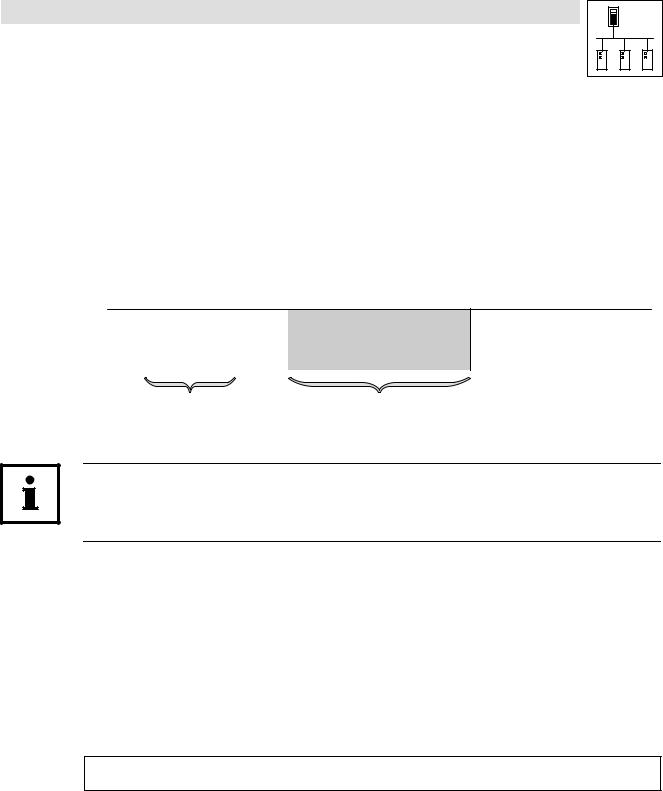
1.1.2 |
Structure of the description |
|
|
|
The descriptions of the individual functions/function blocks as well as of system blocks contained |
||
|
in this Manual have the same structure: |
|
|
|
|
• Headline with SB identifier |
|
|
• ‚ |
‚ SB function and node number |
|
|
|
|
|
|
ƒ |
ƒ Short description of the SB and its most important features |
|
|
|
||
|
„ |
|
|
|
|
„ System block chart including all corresponding variables |
|
|
|
· |
Input variables |
|
… |
· |
Output variables |
|
|
|
|
|
|
… Table giving information about input and output variables: |
|
|
|
· |
Identifier |
|
|
· |
Data type |
|
|
· |
Signal type |
|
|
· |
Address |
|
† |
· |
Display code |
|
|
· |
Display format |
|
|
· |
Information |
|
|
† Detailed functional description of the SB |
|
Information on return values for a function
If it was not possible to carry out a function faultlessly, a negative return value is sent back, representing an error number.
·Each error number is assigned to a corresponding error cause in the Meaning column.
·If different error numbers (−1, −2, ...) may apply, a specific digit (1, 2, ...) in the Priority column additionally is assigned to the error number.
–The smaller this digit, the higher is the priority of the associated error number.
–If several error causes are available at the same time when a function is carried out, always the error number with the highest priority is returned by the function.
L
PLC−Systembus EN 2.0 |
1−3 |
1.1 |
System bus (CAN) for Lenze PLC devices
Preface and general information
About this Manual
1.1.3Pictographs used in this Manual
Pictographs |
Signal words |
|
used |
|
|
Warning of |
Stop! |
Warns of potential damage to material. |
material damage |
|
Possible consequences if disregarded: |
|
|
Damage of the controller/drive system or its environment. |
More notes |
Tip! |
Indicates a tip or note. |
|
Note! |
|
1.1.4Terminology used
Term |
In the following text used for |
|
|
|
|
AIF |
Automation interface |
|
|
|
|
DDS |
Drive PLC Developer Studio |
|
|
|
|
FB |
Function block |
|
|
|
|
FIF |
Function interface |
|
|
|
|
GDC |
Global Drive Control (parameterisation program from Lenze) |
|
|
|
|
Parameter codes |
Codes for setting the function of a function block |
|
|
|
|
PLC |
· |
9300 Servo PLC |
|
· |
Drive PLC |
|
· |
ECSxA |
|
|
|
SB |
System block |
|
|
|
|
System bus |
System bus (CAN): Lenze standard bus system similar to CANopen |
|
|
|
|
1−4 |
PLC−Systembus EN 2.0 |
L |
System bus (CAN) for Lenze PLC devices
General information
2 General information on the system bus (CAN)
2.1Introduction
All Lenze drive and automation systems are provided with an integrated system bus interface for the networking of control components on a field level.
Via the system bus interface, among other things process data and parameter data can be exchanged between the nodes. Furthermore the interface enables the connection of further modules, like for example decentralised terminals, operator and input devices, as well as external controls and host systems.
The system bus interface transfers CAN objects following the CANopen communication profile (CiA DS301, version 4.01), which was developed under the umbrella association of the CiA (CAN in Automation), complying with the CAL (CAN Application Layer).
l
PLC−Systembus EN 2.0 |
2−1 |
System bus (CAN) for Lenze PLC devices
General information
2.2Interfaces of the Lenze PLCs for system bus connection
The following table provides an overview of the Lenze PLC system bus interfaces 9300 Servo PLC,
Drive PLC and ECSxA:
|
CAN objects available |
Information |
|
|
|
|
|
System bus interface CAN |
PDOs |
CAN1_IN/CAN1_OUT |
See chapter 3, "Configuration (CAN system bus |
|
|
CAN2_IN/CAN2_OUT |
interface)". |
|
|
CAN3_IN/CAN3_OUT |
^ 3−1 |
|
|
|
|
|
SDOs |
SDO1 (parameter data channel 1) |
|
|
|
SDO2 (parameter data channel 2) |
|
|
|
|
|
|
|
L_ParRead/L_ParWrite |
Reading/writing of codes. |
|
|
functionality |
See documentation on the LenzeDrive.lib |
|
|
|
function library |
|
|
|
|
|
Sync telegram |
See chapter 3, "Configuration (CAN system bus |
|
|
|
|
interface)". |
|
Synchronisation of the internal time basis |
||
|
^ 3−1 |
||
|
by receiving sync telegrams |
||
|
|
||
|
|
|
|
|
Free CAN objects |
|
|
|
|
|
|
Automation interface (AIF) |
PDOs |
XCAN1_IN/XCAN1_OUT |
See chapter 4, "Configuration (AIF interface)". |
with corresponding fieldbus module |
|
XCAN2_IN/XCAN2_OUT |
^ 4−1 |
(e.g. 2175) |
|
XCAN3_IN/XCAN3_OUT |
|
|
|
|
|
|
SDOs |
XSDO1 (parameter data |
|
|
|
channel 1) |
|
|
|
XSDO2 (parameter data |
|
|
|
channel 2) |
|
|
|
|
|
|
XSync telegram |
|
|
|
|
|
|
Function interface (FIF) |
PDOs |
FIF−CAN1_IN/FIF−CAN1_OUT |
For Drive PLC only! |
with corresponding function module |
|
FIF−CAN2_IN/FIF−CAN2_OUT |
See chapter 5, "Configuration (FIF interface)". |
(e.g. CAN−I/O system bus) |
|
FIF−CAN3_IN/FIF−CAN3_OUT |
^ 5−1 |
|
|
|
|
|
SDOs |
FIF−SDO1 (parameter data |
|
|
|
channel 1) |
|
|
|
FIF−SDO2 (parameter data |
|
|
|
channel 2) |
|
|
|
|
|
|
|
L_ParRead/L_ParWrite |
Reading/writing of codes. |
|
|
functionality |
See documentation on the LenzeDrive.lib |
|
|
|
function library |
|
|
|
|
|
Sync telegram |
See chapter 5, "Configuration (FIF interface)". |
|
|
|
|
^ 5−1 |
|
|
|
|
System bus interface CAN−AUX |
PDOs |
CANaux1_IN/CANaux1_OUT |
For ECSxA only! |
|
|
CANaux2_IN/CANaux2_OUT |
See chapter 6, "Configuration (CAN−AUX system bus |
|
|
CANaux3_IN/CANaux3_OUT |
interface)". |
|
|
|
^ 6−1 |
|
SDOs |
CAN−AUX−SDO (parameter data |
|
|
|
channel) |
|
|
|
|
|
|
|
L_ParRead/L_ParWrite |
Reading/writing of codes. |
|
|
functionality |
See documentation on the function library |
|
|
|
LenzeDrive.lib |
|
|
|
|
|
Sync telegram |
See chapter 6, "Configuration (CAN−AUX system bus |
|
|
|
|
interface)". |
|
|
|
^ 6−1 |
|
|
|
|
2−2 |
PLC−Systembus EN 2.0 |
l |
System bus (CAN) for Lenze PLC devices
General information
2.3Identification of the nodes
Assign a node address − also called Node ID − in the range of 1 to 63 to each node within the system bus network as a definite identification.
· The same node address may not be assigned more than once within the network.
2.4Structure of the CAN telegram
|
|
|
|
|
|
|
Control field |
|
|
|
CRC delimit. ACK delimit. |
|||||||||||||
|
|
|
Start |
|
RTR bit |
|
|
CRC |
|
ACK slot |
|
|
End |
|||||||||||
|
|
|
|
|
|
|
|
|
|
User data 0 ... 8 byte |
sequence |
|
|
|
|
|
|
|
|
|
|
|
||
|
|
|
|
|
Identifier |
|
|
|
|
|
|
|
|
|
|
|
|
|
|
|
|
|
||
|
|
|
|
|
|
|
|
|
|
· |
Network management |
|
|
|
|
|
|
|
|
|
|
|
|
|
|
|
|
1 bit |
11 bit |
1 bit |
6 bit |
· |
Parameter data |
|
15 bit |
1 bit |
1 bit |
1 bit |
7 bit |
|
|
||||||||
|
|
|
· |
Process data |
|
|
||||||||||||||||||
|
|
|
|
|
|
|
|
|
|
|
|
|
|
|
|
|
|
|
|
|
|
|
||
|
|
|
|
|
Description see chapter 2.4.1 |
Description see chapter 2.4.2 |
|
|
|
|
|
|
|
|
|
|
||||||||
|
|
|
|
|
|
|
|
|
|
|
|
|
|
|
|
|
|
|
|
|
|
|||
Fig. 2−1 |
Basic structure of a CAN telegram |
|
|
|
|
|
|
|
|
|
|
|
|
|
|
|||||||||
Tip!
For the user only the identifier and the user data are relevant. All further data of the CAN telegram are processed by the system.
2.4.1Identifier
The principle of the CAN communication is based on a message−oriented data exchange between a transmitter and many receivers. Thereby all nodes practically are able to transmit and receive at the same time.
The control with regard to the node which is to receive a transmitted message is effected via the so−called Identifier in the CAN telegram, also called COB−ID (Communication Object Identifier). For purposes of addressing, the identifier additionally contains information on the priority of the message, as well as on the type of the user data.
The identifier is composed of a so−called basic identifier and the node address of the node to be activated:
Identifier + basic identifier ) node address
·For Lenze devices, the node address is defined via code C0350. (^3−3)
·For the network management and the sync telegram only the basic identifier is required.
l
PLC−Systembus EN 2.0 |
2−3 |
System bus (CAN) for Lenze PLC devices
General information
The following table contains the preset basic identifiers of the Lenze devices:
|
|
Identifier = |
basic identifier |
+ node address of the node |
|||
|
|
|
|
|
|
|
|
|
|
|
dec |
hex |
|
|
|
|
|
|
|
|
|
|
|
·Network management |
|
|
|
|
|
||
|
|
|
|
|
|
|
|
|
Tx (transmission) |
0 |
0 |
|
|
|
|
|
|
|
|
|
|
|
|
|
Rx (reception) |
0 |
0 |
|
|
|
|
|
|
|
|
|
|
|
|
Sync telegram |
|
|
|
|
|
||
|
|
|
|
|
|
|
|
|
Tx (transmission) |
128 |
80 |
|
|
|
|
|
|
|
|
|
|
|
|
|
Rx (reception) |
128 |
80 |
|
|
|
|
|
|
|
|
|
|
|
|
SDOs |
Parameter data channel 1 |
|
|
|
|
|
|
|
|
|
|
|
|
|
|
|
|
Output (transmission) |
1536 |
600 |
+ C0350 |
(CAN) |
|
|
|
|
|
|
+ C2350 |
(XCAN) |
|
|
|
Input (reception) |
1408 |
580 |
|||
|
|
+ C2450 |
(FIF−CAN/CAN−AUX) |
||||
|
|
|
|
|
|
|
|
|
Parameter data channel 2 |
|
|
|
|
|
|
|
|
|
|
|
|
|
|
|
|
Output (transmission) |
1600 |
640 |
+ C0350 |
(CAN) |
|
|
|
|
|
|
+ C2350 |
(XCAN) |
|
|
|
Input (reception) |
1472 |
5C0 |
|||
|
|
+ C2450 |
(FIF−CAN/CAN−AUX) |
||||
|
|
|
|
|
|
|
|
PDOs |
CAN1_IO (cyclic process data) |
|
|
|
|
|
|
|
|
|
|
|
|
|
|
|
|
CAN1_IN |
512 |
200 |
+ C0350 |
(CAN) |
|
|
|
|
|
|
+ C2350 |
(XCAN) |
|
|
|
CAN1_OUT |
384 |
180 |
|||
|
|
+ C2450 |
(FIF−CAN/CAN−AUX) |
||||
|
|
|
|
|
|
|
|
|
CAN2_IO (event− or time−controlled process data) |
|
|
|
|
|
|
|
|
|
|
|
|
|
|
|
|
CAN2_IN |
640 |
280 |
+ C0350 |
(CAN) |
|
|
|
|
|
|
+ C2350 |
(XCAN) |
|
|
|
CAN2_OUT |
641 |
281 |
|||
|
|
+ C2450 |
(FIF−CAN/CAN−AUX) |
||||
|
|
|
|
|
|
|
|
|
CAN3_IO (event− or time−controlled process data) |
|
|
|
|
|
|
|
|
|
|
|
|
|
|
|
|
CAN3_IN |
768 |
300 |
+ C0350 |
(CAN) |
|
|
|
|
|
|
+ C2350 |
(XCAN) |
|
|
|
CAN3_OUT |
769 |
301 |
|||
|
|
+ C2450 |
(FIF−CAN/CAN−AUX) |
||||
|
|
|
|
|
|||
|
|
|
|
|
|
|
|
|
|
|
|
|
|
|
|
Tip!
For the process data objects you can also set an individual identifier via the following codes, which is independent of the node address:
Code |
Interface |
Information |
|
|
|
|
|
C0353 / C0354 |
CAN (system bus interface) |
^ 3−4 |
|
|
|
|
|
C2353 / C2354 |
XCAN (AIF interface) |
^ 4−4 |
|
|
|
|
|
C2453 / C2454 |
FIF−CAN (FIF interface) |
^ 5−4 |
|
|
|
||
CAN−AUX (system bus interface) |
^ 6−4 |
||
|
|||
|
|
|
|
|
|
|
2−4 |
PLC−Systembus EN 2.0 |
l |

System bus (CAN) for Lenze PLC devices
General information
2.4.2User data
Via the user data area of the CAN telegram, three different types of data are transported:
Data type |
Information |
|
|
|
|
|
|
|
|
Network management data |
Information on the structure of communication via the CAN network. |
Chapter 2.5(^ 2−6) |
||
|
|
|
|
|
Process data |
Process data are data for control−oriented concerns, e. g. setpoints and actual |
Chapter 2.6(^ 2−7) |
||
|
values. |
|
|
|
|
· Process data are transmitted as so−called PDOs (Process Data Objects) with a |
|
|
|
|
high priority. |
|
|
|
|
· Process data are processed more quickly by the PLC as parameter data. |
|
|
|
|
· The transmission and reception of the process data is effected by the use of |
|
|
|
|
specific system blocks or the free CAN objects: |
|
|
|
|
|
|
|
|
CAN |
|
SB CAN1_IO for cyclic process data (sync−controlled) |
|
|
(integrated |
|
9300 Servo PLC: |
Chapter 7.1(^ 7−1) |
|
system bus interface) |
|
Drive PLC: |
Chapter 7.2(^ 7−6) |
|
|
|
ECSxA: |
Chapter 7.2(^ 7−6) |
|
|
|
|
|
|
|
|
SB CAN2_IO for event− or time−controlled process data |
Chapter 7.4(^ 7−14) |
|
|
|
|
|
|
|
|
SB CAN3_IO for event− or time−controlled process data |
Chapter 7.5(^ 7−17) |
|
|
|
|
|
|
|
|
|
|
|
XCAN |
|
SB AIF1_IO_AutomationInterface |
See Manual |
|
(automation interface) |
|
for cyclic process data (sync−controlled) |
· |
9300 Servo PLC |
|
|
|
· |
Drive PLC |
|
|
SB AIF2_IO_AutomationInterface |
||
|
|
· |
ECSxA |
|
|
|
for event− or time−controlled process data |
||
|
|
|
|
|
|
|
|
|
|
|
|
SB AIF3_IO_AutomationInterface |
|
|
|
|
for event− or time−controlled process data |
|
|
|
|
|
|
|
|
|
|
|
|
FIF−CAN |
|
SB FIF_CAN1_IO for cyclic process data (sync−controlled) |
Chapter 8.1(^ 8−1) |
|
(function interface, |
|
|
|
|
|
SB FIF_CAN2_IO for event− or time−controlled process data |
Chapter 8.2(^ 8−1) |
||
Drive PLC only! |
|
|||
|
|
|
|
|
|
|
SB FIF_CAN3_IO for event− or time−controlled process data |
Chapter 8.3(^ 8−1) |
|
|
|
|
|
|
|
|
|
|
|
CAN−AUX |
|
SB CANaux1_IO for cyclic process data (sync−controlled) |
Chapter 9.1(^ 9−1) |
|
(integrated |
|
|
|
|
|
SB CANaux2_IO for event− or time−controlled process data |
Chapter 9.2(^ 9−1) |
||
system bus interface, |
|
|||
|
|
|
|
|
ECSxA only) |
|
SB CANaux3_IO for event− or time−controlled process data |
Chapter 9.3(^ 9−1) |
|
|
|
|
|
|
|
|
|
|
|
Free CAN objects |
|
By using the functions/function blocks of the LenzeCanDrv.lib function |
Chapter 10(^ 10−1) |
|
|
|
library, so−called "free CAN objects" additionally can be added to the |
|
|
|
|
fixedly integrated CAN objects. |
|
|
|
|
|
|
|
Parameter data |
For Lenze devices, parameter data are the so−called codes. |
Chapter 2.7(^ 2−11) |
||
|
· Parameter settings for instance are carried out in the case of a one−time |
|
|
|
|
setting of the system during commissioning, or in the case of a material |
|
|
|
|
change of the production machine. |
|
|
|
|
· Parameter data are transferred as so−called SDOs (Service Data Objects) via |
|
|
|
|
the CAN network and are acknowledged by the receiver, i. e. the transmitter |
|
|
|
|
receives a feedback on whether the transmission was successful. |
|
|
|
|
|
|
|
|
l
PLC−Systembus EN 2.0 |
2−5 |
System bus (CAN) for Lenze PLC devices
General information
2.5Network management (NMT)
The CAN telegram for the network management is structured as follows:
11bit |
2 bytes user data |
Identifier
Command |
Device address |
00000000000
· By means of this telegram the master can carry out state changes for the entire CAN network.
Byte 1: command
Command |
Network status |
Information |
|
(hex) |
after change |
|
|
|
|
|
|
01 |
Operational |
The PLC can receive parameter and process data. |
|
|
|
|
|
02 |
Stopped |
The PLC can receive network management telegrams, parameter and process data, however, cannot be |
|
received. |
|||
|
|
||
|
|
|
|
80 |
Pre−operational |
The PLC can receive parameter data. Process data, however, are ignored. |
|
|
|
|
|
81 |
Initialisation |
Reset rode: Changes with regard to the communication−relevant parameters of the system bus (e. g. CAN |
|
|
address, CAN baud rate, etc.) only are accepted after a reset node. |
||
82 |
|||
|
|
||
|
|
|
Byte 2: device address
Device address |
Information |
|
|
0 |
All nodes on the bus are addressed. By this, a state change can be carried out simultaneously for all devices. |
|
|
1...63 |
Node address of the node for which a state change is to be effected. |
|
|
2−6 |
PLC−Systembus EN 2.0 |
l |
System bus (CAN) for Lenze PLC devices
General information
2.6Transmission of process data
Process data are data for control−oriented concerns, e. g. setpoints and actual values.
·Process data are transferred as so−called PDOs (Process Data Objects) with a high priority via the system bus.
·Transmitting and receiving the process data is effected by the use of specific system blocks:
CAN |
XCAN |
FIF−CAN |
CANaux |
|
|
(integrated) |
(AIF interface) |
(FIF interface) |
For ECSxA only! |
Information |
|
|
|
For Drive PLC only! |
|
|
|
|
|
|
|
|
|
CAN1_IO |
AIF1_IO_AutomationInterface |
FIF_CAN1_IO |
CANaux1_IO |
Cyclic process data (sync−controlled) |
|
|
|
|
|
|
|
CAN2_IO |
AIF2_IO_AutomationInterface |
FIF_CAN2_IO |
CANaux2_IO |
Event− or time−controlled process data |
|
|
|
|
|
|
|
CAN3_IO |
AIF3_IO_AutomationInterface |
FIF_CAN3_IO |
CANaux3_IO |
Event− or time−controlled process data |
|
|
|
|
|
|
|
|
|
|
|
|
|
Tip!
In the following subchapters you’ll receive further information on the CAN1_IO ... CAN3_IO process data objects of the CAN interface. This information also applies to the process data objects of the AIF−, FIF− and CAN−AUX interface!
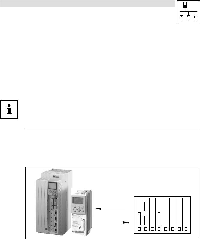
2.6.1Process data channels
Process data channel 1: CAN1_IO
The CAN1_IO SB can be used for the data exchange of cyclic process data (e. g. setpoints and actual values) with a higher−level host system.
cyclic process data (sync−controlled) process data channel 1
CAN1_IN
CAN1_OUT
Host
Fig. 2−2 |
Process data channel 1 (CAN1_IO) for the cyclic data exchange |
l
PLC−Systembus EN 2.0 |
2−7 |
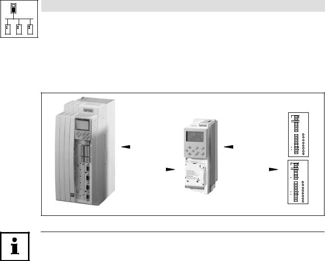
Fig. 2−3
2−8
System bus (CAN) for Lenze PLC devices
General information
Process data channel 2/3: CAN2_IO/CAN3_IO
The SBs CAN2_IO and CAN3_IO are designed for the data exchange of event− or time−controlled process data among the devices. These SBs can also be used for the data exchange with decentralised input/output terminals and higher−level host systems.
event−controlled process data |
event−controlled process data |
|
||||||||||
|
|
process data channel 2 |
process data channel 3 |
|
||||||||
CAN2_IN |
CAN2_OUT |
CAN3_IN |
CAN3_OUT |
|
||||||||
|
||||||||||||
|
||||||||||||
|
||||||||||||
|
||||||||||||
|
||||||||||||
|
|
|
|
|
|
|
|
|
|
|
|
|
|
|
|
|
|
|
|
|
|
|
|
|
|
|
|
|
|
|
|
|
|
|
|
|
|
|
CAN2_OUT |
CAN2_IN |
CAN3_OUT |
CAN3_IN |
|
||||||||
|
|
|
|
|
|
|
|
|
|
|
|
|
|
|
|
|
|
|
|
|
|
|
|
|
|
|
|
|
|
|
|
|
|
|
|
|
|
|
|
|
|
|
|
|
|
|
|
|
|
|
|
|
|
|
|
|
|
|
|
|
|
|
|
|
|
|
|
|
|
|
|
|
|
|
|
|
|
E. g. decentralised terminals
Process data channels 2 and 3 (CAN2_IO/CAN3_IO) for the event− or time−controlled data exchange
Tip!
Detailed information on the CAN1_IO ... CAN3_IO CAN objects integrated in the PLC can be found in the chapter 7, "CAN system blocks":
CAN1_IO for cyclic process data (sync−controlled) |
|
9300 Servo PLC: |
Chapter 7.1(^ 7−1) |
Drive PLC: |
Chapter 7.2(^ 7−6) |
ECSxA: |
Chapter 7.3(^ 7−10) |
|
|
CAN2_IO for event− or time−controlled process data |
Chapter 7.4(^ 7−14) |
|
|
CAN3_IO for event− or time−controlled process data |
Chapter 7.5(^ 7−17) |
|
|
|
|
PLC−Systembus EN 2.0 |
l |
System bus (CAN) for Lenze PLC devices
General information
2.6.2Sync telegram for cyclic process data
For the transmission of cyclic process data, a specific telegram − the sync telegram − is required for the synchronisation.
The sync telegram which has to be generated by a different node initiates the transmission process for the cyclic process data of the PLC and at the same time is the trigger point for the data acceptance of the cyclic process data received in the PLC:
|
Sync telegram |
|
Sync telegram |
|
|
CAN1_OUT |
CAN1_IN |
|
|
|
1. |
2. |
3. |
4. |
Fig. 2−4 |
Synchronisation of the cyclic process data by a sync telegram (without considering the asynchronous data) |
|||
1.After a sync telegram has been received, the cyclic process output data (CAN1_OUT) are sent by the PLC if "respond to sync" has been activated.
2.When the transmission process has been completed, the cyclic process input data (CAN1_IN) are received by the PLC.
3.The data acceptance in the PLC is effected with the next sync telegram.
4.All further telegrams (e. g. for parameters or event−controlled process data) are accepted in an asynchronous manner by the PLC after transmission has been completed.
Tip!
The response to a sync telegram is configured via the following codes:
·for CAN1_OUT via C0366. (^3−7)
·for XCAN1_OUT ... XCAN3_OUT via C2375. (^4−7)
·for FIF−CAN1_OUT via C2466. (^5−7)
·for CANaux1_OUT via C2466. (^5−7)
Also the telegrams of CAN2_OUT and CAN3_OUT can be transferred after a sync telegram, the parameterisation of this function is carried out via the CAN_Management SB.
l
PLC−Systembus EN 2.0 |
2−9 |

System bus (CAN) for Lenze PLC devices
General information
2.6.3Process data telegram
The process data telegram is structured as follows:
11bit |
|
|
|
8 bytes user data |
|
|
|
|
|
|
|
|
|
|
|
|
|
Identifier |
Byte 1 |
Byte 2 |
Byte 3 |
Byte 4 |
Byte 5 |
Byte 6 |
Byte 7 |
Byte 8 |
|
|
|
|
|
|
|
|
|
Identifier
Information on the identifier can be found in chapter 2.4.1. (^2−3)
User data
The 8 bytes user data received or to be transmitted respectively can be read or written simultaneously by several variables of different data types.
Detailed information on the user data can be found in the description to the respective system block:
·CAN system blocks (^7−1 ff.)
·FIF−CAN system blocks (^8−1 ff.)
·CAN−AUX system blocks (^9−1 ff.)
2−10 |
PLC−Systembus EN 2.0 |
l |

System bus (CAN) for Lenze PLC devices
General information
2.7Transmitting parameter data
For Lenze devices, parameter data are the so−called codes.
·Parameter settings for instance are carried out in the case of a one−time setting of the system during commissioning, or in the case of a material change of the production machine.
·Parameter data are transferred as so−called SDOs (Service Data Objects) via the system bus and are acknowledged by the receiver, i. e. the transmitter receives a feedback on whether the transmission was successful.
2.7.1Parameter data telegram
The telegram for parameter data is structured as follows:
11bit |
|
|
|
|
8 bytes user data |
|
|
|
|
|
|
|
|
|
|
|
|
|
|
|
Command |
|
Index |
|
|
|
|
|
|
Identifier |
|
|
|
Subindex |
Data 1 |
Data 2 |
Data 3 |
Data 4 |
|
code |
Low byte |
|
High byte |
||||||
|
|
|
|
|
|
|
|||
|
|
|
|
|
|
|
|
||
|
|
|
|
|
|
|
|
|
|
·In the following subchapters the different components of the telegram are explained in detail.
·An example for writing a parameter can be found in chapter 2.7.2. (^2−15)
·An example for reading a parameter can be found in chapter 2.7.3. (^2−17)
2.7.1.1Identifier
|
Command |
|
Index |
|
|
|
|
|
|
Identifier |
|
|
|
Subindex |
Data 1 |
Data 2 |
Data 3 |
Data 4 |
|
code |
Low byte |
|
High byte |
||||||
|
|||||||||
|
|
|
|
|
|
|
|||
|
|
|
|
|
|
|
|
||
|
|
|
|
|
|
|
|
|
|
For the transmission of parameter data, two parameter data channels are provided, which are addressed via the identifier:
|
|
Identifier = |
basic identifier |
+ node address of the node |
|||
|
|
|
|
|
|
|
|
|
|
|
dec |
hex |
|
|
|
|
|
|
|
|
|
|
|
SDOs |
Parameter data channel 1 |
|
|
|
|
|
|
|
|
|
|
|
|
|
|
|
|
Output (transmission) |
1536 |
600 |
+ C0350 |
(CAN) |
|
|
|
|
|
|
+ C2350 |
(XCAN) |
|
|
|
Input (reception) |
1408 |
580 |
|||
|
|
+ C2450 |
(FIF−CAN/CANaux) |
||||
|
|
|
|
|
|
|
|
|
Parameter data channel 2 |
|
|
|
|
|
|
|
|
|
|
|
|
|
|
|
|
Output (transmission) |
1600 |
640 |
+ C0350 |
(CAN) |
|
|
|
|
|
|
+ C2350 |
(XCAN) |
|
|
|
Input (reception) |
1472 |
5C0 |
|||
|
|
+ C2450 |
(FIF−CAN/CANaux) |
||||
|
|
|
|
|
|||
|
|
|
|
|
|
|
|
|
|
|
|
|
|
|
|
Tip!
Between the identifiers for parameter data channels 1 and 2 there respectively is an offset of 64:
·Output of parameter data channel 1 = 1536
·Output of parameter data channel 2 = 1536 + 64 = 1600
l
PLC−Systembus EN 2.0 |
2−11 |

System bus (CAN) for Lenze PLC devices
General information
2.7.1.2Command code
|
Command |
|
Index |
|
|
|
|
|
|
Identifier |
|
|
|
Subindex |
Data 1 |
Data 2 |
Data 3 |
Data 4 |
|
code |
Low byte |
|
High byte |
||||||
|
|||||||||
|
|
|
|
|
|
|
|||
|
|
|
|
|
|
|
|
||
|
|
|
|
|
|
|
|
|
|
Among other things, the command code contains the command to be carried out as well as information on the parameter data length, and is structured as follows:
|
Bit 7 (MSB) |
Bit 6 |
|
Bit 5 |
Bit 4 |
Bit 3 |
|
Bit 2 |
Bit 1 |
Bit 0 |
|
|
|
|
|
|
|
|
|
|
|
Command |
Command Specifier (cs) |
|
|
|
Length |
e |
s |
|||
|
|
|
|
|
|
|
|
|
|
|
Write request |
0 |
0 |
|
1 |
0 |
|
|
|
1 |
1 |
|
|
|
|
|
|
00 = 4 bytes |
|
|
||
Write response |
0 |
1 |
|
1 |
0 |
0 |
0 |
|||
|
01 = 3 bytes |
|||||||||
|
|
|
|
|
|
|
|
|||
|
|
|
|
|
|
10 = 2 bytes |
|
|
||
Read request |
0 |
1 |
|
0 |
0 |
0 |
0 |
|||
|
|
|
|
|
|
11 = 1 byte |
|
|
||
Read response |
0 |
1 |
|
0 |
0 |
1 |
1 |
|||
|
|
|
|
|||||||
|
|
|
|
|
|
|
|
|
|
|
Error Response |
1 |
0 |
|
0 |
0 |
0 |
|
0 |
0 |
0 |
|
|
|
|
|
|
|
|
|
|
|
Command code for parameters with 1, 2, or 4 bytes data length:
|
4 byte data |
2 byte data |
1 byte data |
|
||||||
|
(32 bit) |
(16 bit) |
(8 bit) |
|
||||||
Command |
hex |
|
dec |
hex |
|
dec |
hex |
|
dec |
Information |
|
|
|
||||||||
|
|
|
|
|
|
|
|
|
|
|
Write Request |
23 |
|
35 |
2B |
|
43 |
2F |
|
47 |
Send parameter to a node |
|
|
|
|
|
|
|
|
|
|
|
Write Response |
60 |
|
96 |
60 |
|
64 |
60 |
|
96 |
Node response to "write request" (acknowledgement) |
|
|
|
|
|
|
|
|
|
|
|
Read Request |
40 |
|
64 |
40 |
|
64 |
40 |
|
64 |
Request for reading a parameter of a node |
|
|
|
|
|
|
|
|
|
|
|
Read Response |
43 |
|
67 |
4B |
|
75 |
4F |
|
79 |
Response to the read request with an actual value |
|
|
|
|
|
|
|
|
|
|
|
Error Response |
80 |
|
128 |
80 |
|
128 |
80 |
|
128 |
Node reports an error with regard to communication |
|
|
|
|
|
|
|
|
|
|
|
"Error Response" command
In the case of this error, an "Error Response" is generated by the node that is addressed.
· This telegram in data 4 always contains the value "6", and in data 3 an error code:
Error Response command code |
Data 3 |
Data 4 |
Error message |
|
|
|
|
|
3 |
|
Access denied |
|
|
|
|
80hex |
5 |
|
Incorrect subindex |
|
6 |
6 |
Incorrect index |
|
|
||
|
|
|
|
C0hex |
8 |
|
Job was not edited |
|
(for 8200 vector + FIF module) |
||
|
|
|
|
2−12 |
PLC−Systembus EN 2.0 |
l |
System bus (CAN) for Lenze PLC devices
General information
2.7.1.3Addressing the parameter (index/subindex)
|
Command |
|
Index |
|
|
|
|
|
|
Identifier |
|
|
|
Subindex |
Data 1 |
Data 2 |
Data 3 |
Data 4 |
|
code |
Low byte |
|
High byte |
||||||
|
|
|
|
|
|
|
|||
|
|
|
|
|
|
|
|
||
|
|
|
|
|
|
|
|
|
|
The addressing of the parameter or of the Lenze code which is to be read or written is effected via the index of the telegram:
Index + 24575 * Lenze code number
·The value for the index is to be entered divided into a low and a high byte in the left−justified Intel format (see example).
·If a subcode is to be addressed, enter the number of the respective subcode in the subindex of the telegram.
·For codes without subcodes, the subindex always receives the value "0".
·The index for Lenze codes is between 40C0hex (16576) and 5FFFhex (24575).
Lenze code |
|
Index |
||
|
|
|
|
|
|
dec |
|
hex |
|
|
|
|
|
|
C0000 |
24575 |
|
5FFF |
|
... |
... |
|
... |
|
C7999 |
16576 |
|
40C0 |
|
|
|
|
|
|
|
|
|
|
|
Tip!
For converting a code number to the corresponding index, the function L_FUNCodeIndexConv in the LenzeDrive.lib function library is provided to you.
Example:
Subcode 1 of code C0168 (fault messages) is to be addressed:
Index + 24575 * 168 + 24407 + 5F57hex
11bit |
|
|
|
|
8 bytes user data |
|
|
|
|
|
|
|
|
|
|
|
|
|
|
|
Command |
|
Index |
|
|
|
|
|
|
Identifier |
|
|
|
Subindex |
Data 1 |
Data 2 |
Data 3 |
Data 4 |
|
code |
Low byte |
|
High byte |
||||||
|
|||||||||
|
|
|
|
|
|
|
|||
|
|
|
|
|
|
|
|
||
|
|
|
|
|
|
|
|
|
|
|
|
57hex |
|
5Fhex |
1hex |
|
|
|
|
l
PLC−Systembus EN 2.0 |
2−13 |
System bus (CAN) for Lenze PLC devices
General information
2.7.1.4Data of the parameter (data 1 ... data 4)
|
Command |
|
Index |
|
|
|
|
|
|
Identifier |
|
|
|
Subindex |
Data 1 |
Data 2 |
Data 3 |
Data 4 |
|
code |
Low byte |
|
High byte |
||||||
|
|||||||||
|
|
|
|
|
|
|
|||
|
|
|
|
|
|
|
|
||
|
|
|
|
|
|
|
|
|
|
For the data of the parameter up to 4 bytes (data 1 ... data 4) are provided.
·The data are presented in the left−justified Intel format with data 1 as LSB and data 4 as MSB (see example).
Example:
For a code in the "Fixed32" data format, the value "20" is to be transmitted.
·"Fixed32" is a fixed point format with 4 decimal positions. Therefore the value has to be multiplied by 10000:
Data1...4 + 20 @ 10000 + 200000 + 00 03 0D 40hex
11bit |
|
|
|
|
8 bytes user data |
|
|
|
|
|
|
|
|
|
|
|
|
|
|
|
|
|
Command |
|
Index |
|
|
|
|
|
|
|
Identifier |
|
|
|
Subindex |
Data 1 |
Data 2 |
Data 3 |
Data 4 |
||
code |
Low byte |
|
High byte |
|||||||
|
|
|
|
|
|
|
|
|||
|
|
|
|
|
|
|
|
|
||
|
|
|
|
|
|
|
|
|
|
|
|
|
|
|
|
|
40hex |
0Dhex |
03hex |
00hex |
|
|
|
|
|
|
|
|
|
|
|
|
|
|
|
|
|
|
(LSB) |
|
|
(MSB) |
|
|
|
|
|
|
|
|
|
|
|
|
|
|
|
|
|
|
|
|
|
|
|
Tip!
The parameters of the Lenze devices are stored in different formats.
Detailed information on this subject can be found in the Manual for the respective PLC in the chapter "Appendix − Table of attributes".
2−14 |
PLC−Systembus EN 2.0 |
l |
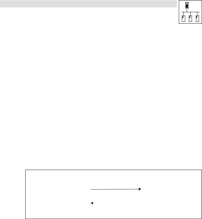
System bus (CAN) for Lenze PLC devices
General information
2.7.2Writing parameters (example)
Task
The acceleration time (C0012) of the controller with the node address 1 is to be set to 20 s via the parameter data channel 1.
Telegram to the controller
|
Formula |
|
|
|
Information |
|
|
|
|
|
|
|
|
|
|
|
|
|
|
|
|
||
Identifier |
= basic identifier + node address |
· Basic identifier for parameter data channel 1 (output) = 1536 |
|
||||||||
|
= 1536 + 1 |
|
|
|
· Node address of the controller = 1 |
|
|
|
|||
|
= 1537 |
|
|
|
|
|
|
|
|
|
|
|
|
|
|
|
|
|
|
|
|
|
|
Command code |
= 23hex |
|
|
|
· Command "Write Request" (send parameter to controller) |
|
|||||
Index |
= 24575 − number of the Lenze code |
· Code = C0012 (acceleration time) |
|
|
|
||||||
|
= 24575 − 12 |
|
|
|
|
|
|
|
|
|
|
|
= 24563 |
|
|
|
|
|
|
|
|
|
|
|
= 5F F3hex |
|
|
|
|
|
|
|
|
|
|
Subindex |
= 0 |
|
|
|
· Subcode = 0 (no subcode) |
|
|
|
|
||
|
|
|
|
|
|
|
|
|
|
|
|
Data 1 ... 4 |
= 20 x 10000 |
|
|
|
· Value = 20 s |
|
|
|
|
|
|
|
= 200000 |
|
|
|
· Fixed32 data format (4 fixed decimal positions); multiply value by 10000 |
||||||
|
= 00 03 0D 40hex |
|
|
|
|
|
|
|
|
|
|
|
|
|
|
|
|
|
|
|
|
|
|
11bit |
|
|
|
|
8 bytes user data |
|
|
|
|
||
|
|
|
|
|
|
|
|
|
|
|
|
|
Command |
|
Index |
|
|
|
|
|
|
|
|
Identifier |
|
|
|
Subindex |
|
Data 1 |
Data 2 |
Data 3 |
|
Data 4 |
|
code |
Low byte |
|
High byte |
|
|
||||||
|
|
|
|||||||||
|
|
|
|
|
|
|
|
|
|||
|
|
|
|
|
|
|
|
|
|
||
|
|
|
|
|
|
|
|
|
|
|
|
1537 |
23hex |
F3hex |
|
5Fhex |
0 |
|
40hex |
0Dhex |
03hex |
|
00hex |
|
|
|
|
|
|
|
(LSB) |
|
|
|
(MSB) |
|
|
|
|
|
|
|
|
|
|
|
|
|
|
|
|
L |
|
Write Request |
Identifier = 1537 |
|
|
|
|
|
|
|
|||
(C0012 = 20 s) |
|
|
|
||
|
|
|
|
|
|
Write Response |
Identifier = 1409 |
|
|
|
|
|
|
|
|||
|
|
|
|
|
|
|
|
|
|
|
|
|
|
|
|
|
|
|
SDO 1 / Node-ID 1 |
||||
Fig. 2−5 Writing parameters
l
PLC−Systembus EN 2.0 |
2−15 |

System bus (CAN) for Lenze PLC devices
General information
Telegram from controller (acknowledgement if carried out correctly)
|
Formula |
|
|
|
Information |
|
|
|
|
|
|
|
|
|
|
|
|
|
|
|
|
|
|
Identifier |
= basic identifier + node address |
|
· Basic identifier for parameter data channel 1 (input) = 1408 |
|
|||||||
|
= 1408 + 1 |
|
|
|
· Node address of the controller = 1 |
|
|
|
|||
|
= 1409 |
|
|
|
|
|
|
|
|
|
|
|
|
|
|
|
|
|
|
|
|
||
Command code |
= 60hex |
|
|
|
· "Write Response" command (acknowledgement by the controller) |
||||||
Index |
= index of the read request |
|
|
|
|
|
|
|
|
||
|
|
|
|
|
|
|
|
|
|
|
|
Subindex |
= subindex of the read request |
|
|
|
|
|
|
|
|
||
|
|
|
|
|
|
|
|
|
|
|
|
Data 1 ... 4 |
= 0 |
|
|
|
· |
Acknowledgement only |
|
|
|
|
|
|
|
|
|
|
|
|
|
|
|
|
|
11bit |
|
|
|
|
|
8 bytes user data |
|
|
|
|
|
|
|
|
|
|
|
|
|
|
|
||
|
Command |
Index |
|
|
|
|
|
|
|
||
Identifier |
|
|
|
|
Subindex |
Data 1 |
Data 2 |
Data 3 |
|
Data 4 |
|
code |
Low byte |
|
High byte |
|
|
||||||
|
|
|
|||||||||
|
|
|
|
|
|
|
|
|
|||
|
|
|
|
|
|
|
|
|
|
||
|
|
|
|
|
|
|
|
|
|
|
|
1409 |
60hex |
F3hex |
|
5Fhex |
|
0 |
0 |
0 |
0 |
|
0 |
2−16 |
PLC−Systembus EN 2.0 |
l |
System bus (CAN) for Lenze PLC devices
General information
2.7.3Reading a parameter (example)
Task
The heatsink temperature (C0061) of the controller with the node address 5 is to be read via the parameter data channel 1.
Telegram to the controller
|
Formula |
|
|
|
Information |
|
|
|
|
|
|
|
|
|
|
|
|
|
|
|
|
Identifier |
= basic identifier + node address |
· Basic identifier for parameter data channel 1 (output) = 1536 |
|
|||||||
|
= 1536 + 5 |
|
|
|
· Node address of the controller = 5 |
|
|
|
||
|
= 1541 |
|
|
|
|
|
|
|
|
|
|
|
|
|
|
|
|
|
|
|
|
Command code |
= 40hex |
|
|
|
· Command "Read Request" (request to read a parameter from the |
|||||
|
|
|
|
|
controller) |
|
|
|
|
|
|
|
|
|
|
|
|
|
|
|
|
Index |
= 24575 − number of the Lenze code |
· Code = C0061 (heatsink temperature) |
|
|
|
|||||
|
= 24575 − 61 |
|
|
|
|
|
|
|
|
|
|
= 24514 |
|
|
|
|
|
|
|
|
|
|
= 5F C2hex |
|
|
|
|
|
|
|
|
|
Subindex |
= 0 |
|
|
|
· Subcode = 0 (no subcode) |
|
|
|
|
|
|
|
|
|
|
|
|
|
|
|
|
Data 1 ... 4 |
= 0 |
|
|
|
· Read request only |
|
|
|
|
|
|
|
|
|
|
|
|
|
|
|
|
|
|
|
|
|
|
|
|
|
|
|
11bit |
|
|
|
|
8 bytes user data |
|
|
|
|
|
|
|
|
|
|
|
|
|
|
|
|
|
Command |
|
Index |
|
|
|
|
|
|
|
Identifier |
|
|
|
Subindex |
Data 1 |
Data 2 |
Data 3 |
|
Data 4 |
|
code |
Low byte |
|
High byte |
|
||||||
|
|
|||||||||
|
|
|
|
|
|
|
|
|||
|
|
|
|
|
|
|
|
|
||
|
|
|
|
|
|
|
|
|
|
|
1541 |
40hex |
C2hex |
|
5Fhex |
0 |
0 |
0 |
0 |
|
0 |
|
|
L |
|
Read Request |
Identifier = 1541 |
|
|
|
|
||
(C0061 = ???) |
|
|
|
|
|
|
|
|
|
|
|
Identifier = 1413
Read Response (C0061 = 43 ºC)
SDO 1 / Node-ID 5
Fig. 2−6 |
Reading parameters |
l
PLC−Systembus EN 2.0 |
2−17 |

System bus (CAN) for Lenze PLC devices
General information
Telegram from the controller (value of the parameter requested)
|
Formula |
|
|
|
Information |
|
|
|
|
|
|
|
|
|
|
|
|
|
|
|
|
|
|
Identifier |
= basic identifier + node address |
|
· Basic identifier for parameter data channel 1 (input) = 1408 |
|
|||||||
|
= 1408 + 5 |
|
|
|
· Node address of the controller = 5 |
|
|
|
|||
|
= 1413 |
|
|
|
|
|
|
|
|
|
|
|
|
|
|
|
|
|
|
|
|
||
Command code |
= 43hex |
|
|
|
· "Read Response" command (response to the read request with the |
||||||
|
|
|
|
|
current value) |
|
|
|
|
|
|
|
|
|
|
|
|
|
|
|
|
|
|
Index |
= index of the read request |
|
|
|
|
|
|
|
|
||
|
|
|
|
|
|
|
|
|
|
|
|
Subindex |
= subindex of the read request |
|
|
|
|
|
|
|
|
||
|
|
|
|
|
|
|
|
|
|
||
Data 1 ... 4 |
= 43 x 10000 |
|
|
|
· Assumption: The current heatsink temperature of the controller is 43 ºC, |
||||||
|
= 430000 |
|
|
|
therefore the value of the parameter to be read is 43 |
|
|||||
|
= 00 06 8F B0hex |
|
· Fixed32 data format (4 fixed decimal positions); multiply value by 10000 |
||||||||
|
|
|
|
|
|
|
|
|
|
|
|
11bit |
|
|
|
|
8 bytes user data |
|
|
|
|
||
|
|
|
|
|
|
|
|
|
|
|
|
|
Command |
Index |
|
|
|
|
|
|
|
||
Identifier |
|
|
|
Subindex |
|
Data 1 |
Data 2 |
Data 3 |
|
Data 4 |
|
code |
Low byte |
|
High byte |
|
|
||||||
|
|
|
|||||||||
|
|
|
|
|
|
|
|
|
|||
|
|
|
|
|
|
|
|
|
|
||
|
|
|
|
|
|
|
|
|
|
|
|
1413 |
43hex |
C2hex |
|
5Fhex |
0 |
|
B0hex |
8Fhex |
06hex |
|
00hex |
|
|
|
|
|
|
|
|
|
|
|
|
|
|
|
|
|
|
|
(LSB) |
|
|
|
(MSB) |
|
|
|
|
|
|
|
|
|
|
|
|
2−18 |
PLC−Systembus EN 2.0 |
l |
Loading...