


 Loading...
Accessories
PROFIBUS® E84AYCPM
Inverter Drives 8400 _ _ _ _ _ _ _ _ _ _ _ _ _ _ _ _ _ _ _ _ _ _ _ _ |
Communication Manual |
EN |
Ä.K6~ä 13422193
L
Contents
_ _ _ _ _ _ _ _ _ _ _ _ _ _ _ _ _ _ _ _ _ _ _ _ _ _ _ _ _ _ _ _ _ _ _ _ _ _ _ _ _ _ _ _ _ _ _ _ _ _ _ _ _ _ _ _ _ _ _ _ _ _ _ _
1 |
About this documentation _ _ _ _ _ _ _ _ _ _ _ _ _ _ _ _ _ _ _ _ _ _ _ _ _ _ _ _ _ _ _ _ _ _ _ _ _ _ _ |
5 |
||||
1.1 |
Document history |
_ _ _ _ _ _ _ _ _ _ _ _ _ _ _ _ _ _ _ _ _ _ _ _ _ _ _ _ _ _ _ _ _ _ _ _ _ _ _ _ _ _ _ _ |
7 |
|||
1.2 |
Conventions used |
_ _ _ _ _ _ _ _ _ _ _ _ _ _ _ _ _ _ _ _ _ _ _ _ _ _ _ _ _ _ _ _ _ _ _ _ _ _ _ _ _ _ _ _ |
8 |
|||
1.3 |
Terminology used |
_ _ _ _ _ _ _ _ _ _ _ _ _ _ _ _ _ _ _ _ _ _ _ _ _ _ _ _ _ _ _ _ _ _ _ _ _ _ _ _ _ _ _ _ |
9 |
|||
1.4 |
Notes used _ _ _ _ _ _ _ _ _ _ _ _ _ _ _ _ _ _ _ _ _ _ _ _ _ _ _ _ _ _ _ _ _ _ _ _ _ _ _ _ _ _ _ _ _ _ _ _ |
10 |
||||
2 |
Safety instructions _ _ _ _ _ _ _ _ _ _ _ _ _ _ _ _ _ _ _ _ _ _ _ _ _ _ _ _ _ _ _ _ _ _ _ _ _ _ _ _ _ _ _ _ |
11 |
||||
2.1 |
General safety and application instructions _ _ _ _ _ _ _ _ _ _ _ _ _ _ _ _ _ _ _ _ _ _ _ _ _ _ _ _ _ _ |
11 |
||||
2.2 |
Deviceand application-specific safety instructions _ _ _ _ _ _ _ _ _ _ _ _ _ _ _ _ _ _ _ _ _ _ _ _ _ _ |
12 |
||||
2.3 |
Residual hazards _ _ _ _ _ _ _ _ _ _ _ _ _ _ _ _ _ _ _ _ _ _ _ _ _ _ _ _ _ _ _ _ _ _ _ _ _ _ _ _ _ _ _ _ _ |
12 |
||||
3 |
Product description _ _ _ _ _ _ _ _ _ _ _ _ _ _ _ _ _ _ _ _ _ _ _ _ _ _ _ _ _ _ _ _ _ _ _ _ _ _ _ _ _ _ _ |
13 |
||||
3.1 |
Application as directed |
_ _ _ _ _ _ _ _ _ _ _ _ _ _ _ _ _ _ _ _ _ _ _ _ _ _ _ _ _ _ _ _ _ _ _ _ _ _ _ _ _ |
13 |
|||
3.2 |
Identification _ _ _ _ _ _ _ _ _ _ _ _ _ _ _ _ _ _ _ _ _ _ _ _ _ _ _ _ _ _ _ _ _ _ _ _ _ _ _ _ _ _ _ _ _ _ _ |
13 |
||||
3.3 |
Features _ _ _ _ _ _ _ _ _ _ _ _ _ _ _ _ _ _ _ _ _ _ _ _ _ _ _ _ _ _ _ _ _ _ _ _ _ _ _ _ _ _ _ _ _ _ _ _ _ |
14 |
||||
3.4 |
Terminals and interfaces _ _ _ _ _ _ _ _ _ _ _ _ _ _ _ _ _ _ _ _ _ _ _ _ _ _ _ _ _ _ _ _ _ _ _ _ _ _ _ _ |
14 |
||||
4 |
Technical data _ _ _ _ _ _ _ _ _ _ _ _ _ _ _ _ _ _ _ _ _ _ _ _ _ _ _ _ _ _ _ _ _ _ _ _ _ _ _ _ _ _ _ _ _ _ |
15 |
||||
4.1 |
General data and operating conditions |
_ _ _ _ _ _ _ _ _ _ _ _ _ _ _ _ _ _ _ _ _ _ _ _ _ _ _ _ _ _ _ _ |
15 |
|||
4.2 |
Protective insulation |
_ _ _ _ _ _ _ _ _ _ _ _ _ _ _ _ _ _ _ _ _ _ _ _ _ _ _ _ _ _ _ _ _ _ _ _ _ _ _ _ _ _ |
16 |
|||
4.3 |
Protocol data _ _ _ _ _ _ _ _ _ _ _ _ _ _ _ _ _ _ _ _ _ _ _ _ _ _ _ _ _ _ _ _ _ _ _ _ _ _ _ _ _ _ _ _ _ _ _ |
19 |
||||
4.4 |
Communication time |
_ _ _ _ _ _ _ _ _ _ _ _ _ _ _ _ _ _ _ _ _ _ _ _ _ _ _ _ _ _ _ _ _ _ _ _ _ _ _ _ _ _ |
19 |
|||
4.5 |
Dimensions _ _ _ _ _ _ _ _ _ _ _ _ _ _ _ _ _ _ _ _ _ _ _ _ _ _ _ _ _ _ _ _ _ _ _ _ _ _ _ _ _ _ _ _ _ _ _ |
20 |
||||
5 |
Installation _ _ _ _ _ _ _ _ _ _ _ _ _ _ _ _ _ _ _ _ _ _ _ _ _ _ _ _ _ _ _ _ _ _ _ _ _ _ _ _ _ _ _ _ _ _ _ _ |
21 |
||||
5.1 |
Mechanical installation _ _ _ _ _ _ _ _ _ _ _ _ _ _ _ _ _ _ _ _ _ _ _ _ _ _ _ _ _ _ _ _ _ _ _ _ _ _ _ _ _ |
22 |
||||
|
5.1.1 |
Mounting for 0.25 kW and 0.37 kW standard devices _ _ _ _ _ _ _ _ _ _ _ _ _ _ _ _ _ _ _ _ |
22 |
|||
|
5.1.2 |
Mounting for standard devices of 0.55 kW and more _ _ _ _ _ _ _ _ _ _ _ _ _ _ _ _ _ _ _ _ |
23 |
|||
|
5.1.3 |
Replacing the communication module _ _ _ _ _ _ _ _ _ _ _ _ _ _ _ _ _ _ _ _ _ _ _ _ _ _ _ _ |
24 |
|||
5.2 |
Electrical installation |
_ _ _ _ _ _ _ _ _ _ _ _ _ _ _ _ _ _ _ _ _ _ _ _ _ _ _ _ _ _ _ _ _ _ _ _ _ _ _ _ _ _ |
25 |
|||
|
5.2.1 |
Network topology _ _ _ _ _ _ _ _ _ _ _ _ _ _ _ _ _ _ _ _ _ _ _ _ _ _ _ _ _ _ _ _ _ _ _ _ _ _ _ |
25 |
|||
5.3 |
Activating the bus terminating resistor |
_ _ _ _ _ _ _ _ _ _ _ _ _ _ _ _ _ _ _ _ _ _ _ _ _ _ _ _ _ _ _ _ |
27 |
|||
|
5.3.1 Bus cable specification _ _ _ _ _ _ _ _ _ _ _ _ _ _ _ _ _ _ _ _ _ _ _ _ _ _ _ _ _ _ _ _ _ _ _ _ _ |
28 |
||||
|
5.3.2 |
PROFIBUS connection _ _ _ _ _ _ _ _ _ _ _ _ _ _ _ _ _ _ _ _ _ _ _ _ _ _ _ _ _ _ _ _ _ _ _ _ _ |
29 |
|||
6 |
Commissioning _ _ _ _ _ _ _ _ _ _ _ _ _ _ _ _ _ _ _ _ _ _ _ _ _ _ _ _ _ _ _ _ _ _ _ _ _ _ _ _ _ _ _ _ _ |
30 |
||||
6.1 |
Before initial switch-on _ _ _ _ _ _ _ _ _ _ _ _ _ _ _ _ _ _ _ _ _ _ _ _ _ _ _ _ _ _ _ _ _ _ _ _ _ _ _ _ _ |
30 |
||||
6.2 |
Configuration of the controller (master) _ _ _ _ _ _ _ _ _ _ _ _ _ _ _ _ _ _ _ _ _ _ _ _ _ _ _ _ _ _ _ _ |
31 |
||||
6.3 |
Setting the station address _ _ _ _ _ _ _ _ _ _ _ _ _ _ _ _ _ _ _ _ _ _ _ _ _ _ _ _ _ _ _ _ _ _ _ _ _ _ _ |
32 |
||||
6.4 |
Initial switch-on _ _ _ _ _ _ _ _ _ _ _ _ _ _ _ _ _ _ _ _ _ _ _ _ _ _ _ _ _ _ _ _ _ _ _ _ _ _ _ _ _ _ _ _ _ |
34 |
||||
6.5 |
Going online with »Engineer« via TCI |
_ _ _ _ _ _ _ _ _ _ _ _ _ _ _ _ _ _ _ _ _ _ _ _ _ _ _ _ _ _ _ _ _ |
35 |
|||
7 |
Data transfer _ _ _ _ _ _ _ _ _ _ _ _ _ _ _ _ _ _ _ _ _ _ _ _ _ _ _ _ _ _ _ _ _ _ _ _ _ _ _ _ _ _ _ _ _ _ _ |
44 |
||||
8 |
Process data transfer _ _ _ _ _ _ _ _ _ _ _ _ _ _ _ _ _ _ _ _ _ _ _ _ _ _ _ _ _ _ _ _ _ _ _ _ _ _ _ _ _ _ |
45 |
||||
8.1 |
Access to process data / PDO mapping _ _ _ _ _ _ _ _ _ _ _ _ _ _ _ _ _ _ _ _ _ _ _ _ _ _ _ _ _ _ _ _ _ |
45 |
||||
8.2 |
Preconfigured port interconnection of the process data objects (PDO) _ _ _ _ _ _ _ _ _ _ _ _ _ _ _ |
46 |
||||
8.3 |
Free configuration of the port interconnection of process data objects (PDO) _ _ _ _ _ _ _ _ _ _ _ _ |
47 |
||||
2 |
Lenze · E84AYCPM communication module (PROFIBUS®) · Communication Manual · DMS 5.0 EN · 11/2012 · TD17 |
Contents
_ _ _ _ _ _ _ _ _ _ _ _ _ _ _ _ _ _ _ _ _ _ _ _ _ _ _ _ _ _ _ _ _ _ _ _ _ _ _ _ _ _ _ _ _ _ _ _ _ _ _ _ _ _ _ _ _ _ _ _ _ _ _ _
9 |
Parameter data transfer _ _ _ _ _ _ _ _ _ _ _ _ _ _ _ _ _ _ _ _ _ _ _ _ _ _ _ _ _ _ _ _ _ _ _ _ _ _ _ _ _ |
51 |
|||||||||
9.1 |
Addressing of the parameter data _ _ _ _ _ _ _ _ _ _ _ _ _ _ _ _ _ _ _ _ _ _ _ _ _ _ _ _ _ _ _ _ _ _ _ |
51 |
|||||||||
9.2 |
DRIVECOM parameter data channel (DP-V0) |
_ _ _ _ _ _ _ _ _ _ _ _ _ _ _ _ _ _ _ _ _ _ _ _ _ _ _ _ _ |
52 |
||||||||
|
9.2.1 |
Telegram structure (overview) |
_ _ _ _ _ _ _ _ _ _ _ _ _ _ _ _ _ _ _ _ _ _ _ _ _ _ _ _ _ _ _ _ |
52 |
|||||||
|
9.2.2 |
Byte 1: Service _ _ _ _ _ _ _ _ _ _ _ _ _ _ _ _ _ _ _ _ _ _ _ _ _ _ _ _ _ _ _ _ _ _ _ _ _ _ _ _ _ |
53 |
||||||||
|
|
9.2.2.1 |
Reading parameter data from the inverter |
_ _ _ _ _ _ _ _ _ _ _ _ _ _ _ _ _ _ _ |
54 |
||||||
|
|
9.2.2.2 |
Writing parameter data to the inverter |
_ _ _ _ _ _ _ _ _ _ _ _ _ _ _ _ _ _ _ _ _ |
54 |
||||||
|
|
9.2.2.3 |
Abort of data transfer by the inverter |
_ _ _ _ _ _ _ _ _ _ _ _ _ _ _ _ _ _ _ _ _ _ |
55 |
||||||
|
|
9.2.2.4 |
Data transfer abort by the master |
_ _ _ _ _ _ _ _ _ _ _ _ _ _ _ _ _ _ _ _ _ _ _ _ |
55 |
||||||
|
9.2.3 |
Byte 2: Subindex _ _ _ _ _ _ _ _ _ _ _ _ _ _ _ _ _ _ _ _ _ _ _ _ _ _ _ _ _ _ _ _ _ _ _ _ _ _ _ _ |
56 |
||||||||
|
9.2.4 |
Bytes 3 + 4: Index |
_ _ _ _ _ _ _ _ _ _ _ _ _ _ _ _ _ _ _ _ _ _ _ _ _ _ _ _ _ _ _ _ _ _ _ _ _ _ _ |
56 |
|||||||
|
9.2.5 |
Bytes 5 ... 8: Parameter value / error information |
_ _ _ _ _ _ _ _ _ _ _ _ _ _ _ _ _ _ _ _ _ _ |
57 |
|||||||
|
9.2.6 |
Error codes |
_ _ _ _ _ _ _ _ _ _ _ _ _ _ _ _ _ _ _ _ _ _ _ _ _ _ _ _ _ _ _ _ _ _ _ _ _ _ _ _ _ _ _ |
58 |
|||||||
|
9.2.7 |
Telegram examples |
_ _ _ _ _ _ _ _ _ _ _ _ _ _ _ _ _ _ _ _ _ _ _ _ _ _ _ _ _ _ _ _ _ _ _ _ _ _ |
59 |
|||||||
|
|
9.2.7.1 |
Read request: Querying the heatsink temperature _ _ _ _ _ _ _ _ _ _ _ _ _ _ _ |
59 |
|||||||
|
|
9.2.7.2 |
Write request: Setting the deceleration time for quick stop (QSP) _ _ _ _ _ _ _ |
60 |
|||||||
9.3 |
PROFIdrive parameter data channel (DP-V1) _ _ _ _ _ _ _ _ _ _ _ _ _ _ _ _ _ _ _ _ _ _ _ _ _ _ _ _ _ _ |
61 |
|||||||||
|
9.3.1 |
Connection establishment between master and slave |
_ _ _ _ _ _ _ _ _ _ _ _ _ _ _ _ _ _ _ |
62 |
|||||||
|
9.3.2 |
Acyclic data transfer _ _ _ _ _ _ _ _ _ _ _ _ _ _ _ _ _ _ _ _ _ _ _ _ _ _ _ _ _ _ _ _ _ _ _ _ _ _ |
63 |
||||||||
|
9.3.3 |
Telegram structure _ _ _ _ _ _ _ _ _ _ _ _ _ _ _ _ _ _ _ _ _ _ _ _ _ _ _ _ _ _ _ _ _ _ _ _ _ _ _ |
64 |
||||||||
|
|
9.3.3.1 |
Reading parameter data from the inverter |
_ _ _ _ _ _ _ _ _ _ _ _ _ _ _ _ _ _ _ |
65 |
||||||
|
|
9.3.3.2 |
Response to a correctly executed read request _ _ _ _ _ _ _ _ _ _ _ _ _ _ _ _ _ |
66 |
|||||||
|
|
9.3.3.3 |
Response to a read error |
_ _ _ _ _ _ _ _ _ _ _ _ _ _ _ _ _ _ _ _ _ _ _ _ _ _ _ _ _ |
68 |
||||||
|
|
9.3.3.4 |
Writing parameter data to the inverter |
_ _ _ _ _ _ _ _ _ _ _ _ _ _ _ _ _ _ _ _ _ |
70 |
||||||
|
|
9.3.3.5 |
Response to a correctly executed write request _ _ _ _ _ _ _ _ _ _ _ _ _ _ _ _ _ |
72 |
|||||||
|
|
9.3.3.6 |
Response to a write error |
_ _ _ _ _ _ _ _ _ _ _ _ _ _ _ _ _ _ _ _ _ _ _ _ _ _ _ _ _ |
73 |
||||||
|
9.3.4 |
Error codes |
_ _ _ _ _ _ _ _ _ _ _ _ _ _ _ _ _ _ _ _ _ _ _ _ _ _ _ _ _ _ _ _ _ _ _ _ _ _ _ _ _ _ _ |
74 |
|||||||
|
9.3.5 |
Telegram examples |
_ _ _ _ _ _ _ _ _ _ _ _ _ _ _ _ _ _ _ _ _ _ _ _ _ _ _ _ _ _ _ _ _ _ _ _ _ _ |
76 |
|||||||
|
|
9.3.5.1 |
Read request: Querying the heatsink temperature _ _ _ _ _ _ _ _ _ _ _ _ _ _ _ |
76 |
|||||||
|
|
9.3.5.2 |
Write request: Setting the deceleration time for quick stop (QSP) _ _ _ _ _ _ _ |
78 |
|||||||
9.4 |
Consistent parameter data |
_ _ _ _ _ _ _ _ _ _ _ _ _ _ _ _ _ _ _ _ _ _ _ _ _ _ _ _ _ _ _ _ _ _ _ _ _ _ _ |
80 |
||||||||
10 |
Monitoring _ _ _ _ _ _ _ _ _ _ _ _ _ _ _ _ _ _ _ _ _ _ _ _ _ _ _ _ _ _ _ _ _ _ _ _ _ _ _ _ _ _ _ _ _ _ _ _ |
81 |
|||||||||
10.1 |
Permanent interruption of PROFIBUS communication |
_ _ _ _ _ _ _ _ _ _ _ _ _ _ _ _ _ _ _ _ _ _ _ _ |
81 |
||||||||
10.2 |
Short-time interruption of PROFIBUS communication |
_ _ _ _ _ _ _ _ _ _ _ _ _ _ _ _ _ _ _ _ _ _ _ _ |
82 |
||||||||
10.3 |
Settings and displays in the »Engineer« |
_ _ _ _ _ _ _ _ _ _ _ _ _ _ _ _ _ _ _ _ _ _ _ _ _ _ _ _ _ _ _ _ |
83 |
||||||||
11 |
Diagnostics _ _ _ _ _ _ _ _ _ _ _ _ _ _ _ _ _ _ _ _ _ _ _ _ _ _ _ _ _ _ _ _ _ _ _ _ _ _ _ _ _ _ _ _ _ _ _ _ |
84 |
|||||||||
11.1 |
LED status displays |
_ _ _ _ _ _ _ _ _ _ _ _ _ _ _ _ _ _ _ _ _ _ _ _ _ _ _ _ _ _ _ _ _ _ _ _ _ _ _ _ _ _ _ |
84 |
||||||||
|
11.1.1 |
Module status displays |
_ _ _ _ _ _ _ _ _ _ _ _ _ _ _ _ _ _ _ _ _ _ _ _ _ _ _ _ _ _ _ _ _ _ _ _ |
85 |
|||||||
|
11.1.2 |
Fieldbus status displays |
_ _ _ _ _ _ _ _ _ _ _ _ _ _ _ _ _ _ _ _ _ _ _ _ _ _ _ _ _ _ _ _ _ _ _ _ |
86 |
|||||||
11.2 |
Diagnosing with the »Engineer« |
_ _ _ _ _ _ _ _ _ _ _ _ _ _ _ _ _ _ _ _ _ _ _ _ _ _ _ _ _ _ _ _ _ _ _ _ |
87 |
||||||||
11.3 |
Advanced diagnostic message _ _ _ _ _ _ _ _ _ _ _ _ _ _ _ _ _ _ _ _ _ _ _ _ _ _ _ _ _ _ _ _ _ _ _ _ _ |
89 |
|||||||||
12 |
Error messages _ _ _ _ _ _ _ _ _ _ _ _ _ _ _ _ _ _ _ _ _ _ _ _ _ _ _ _ _ _ _ _ _ _ _ _ _ _ _ _ _ _ _ _ _ _ |
91 |
|||||||||
12.1 |
Short overview of the PROFIBUS error messages _ _ _ _ _ _ _ _ _ _ _ _ _ _ _ _ _ _ _ _ _ _ _ _ _ _ _ |
91 |
|||||||||
12.2 |
Possible causes and remedies _ _ _ _ _ _ _ _ _ _ _ _ _ _ _ _ _ _ _ _ _ _ _ _ _ _ _ _ _ _ _ _ _ _ _ _ _ _ |
92 |
|||||||||
Lenze · E84AYCPM communication module (PROFIBUS®) · Communication Manual · DMS 5.0 EN · 11/2012 · TD17 |
3 |
Contents
_ _ _ _ _ _ _ _ _ _ _ _ _ _ _ _ _ _ _ _ _ _ _ _ _ _ _ _ _ _ _ _ _ _ _ _ _ _ _ _ _ _ _ _ _ _ _ _ _ _ _ _ _ _ _ _ _ _ _ _ _ _ _ _
13 |
Parameter reference _ _ _ _ _ _ _ _ _ _ _ _ _ _ _ _ _ _ _ _ _ _ _ _ _ _ _ _ _ _ _ _ _ _ _ _ _ _ _ _ _ _ _ |
95 |
13.1 |
Parameters of the communication module _ _ _ _ _ _ _ _ _ _ _ _ _ _ _ _ _ _ _ _ _ _ _ _ _ _ _ _ _ _ |
95 |
13.2 |
Table of attributes _ _ _ _ _ _ _ _ _ _ _ _ _ _ _ _ _ _ _ _ _ _ _ _ _ _ _ _ _ _ _ _ _ _ _ _ _ _ _ _ _ _ _ _ |
103 |
13.3 |
Implemented PROFIdrive objects (DP-V1) _ _ _ _ _ _ _ _ _ _ _ _ _ _ _ _ _ _ _ _ _ _ _ _ _ _ _ _ _ _ _ |
105 |
14 |
DIP switch positions for setting the station address _ _ _ _ _ _ _ _ _ _ _ _ _ _ _ _ _ _ _ _ _ _ _ _ _ |
107 |
|
Your opinion is important to us _ _ _ _ _ _ _ _ _ _ _ _ _ _ _ _ _ _ _ _ _ _ _ _ _ _ _ _ _ _ _ _ _ _ _ _ _ |
114 |
4 |
Lenze · E84AYCPM communication module (PROFIBUS®) · Communication Manual · DMS 5.0 EN · 11/2012 · TD17 |

1 About this documentation
_ _ _ _ _ _ _ _ _ _ _ _ _ _ _ _ _ _ _ _ _ _ _ _ _ _ _ _ _ _ _ _ _ _ _ _ _ _ _ _ _ _ _ _ _ _ _ _ _ _ _ _ _ _ _ _ _ _ _ _ _ _ _ _
1 About this documentation
This documentation exclusively describes the E84AYCPM communication module (PROFIBUS).
Note!
This documentation supplements the mounting instructions supplied with the communication module and the "Inverter Drives 8400" hardware manual.
The hardware manual contains safety instructions which must be observed!
The features and functions of the communication module are described in detail. Typical applications are explained with the help of examples.
The theoretical connections are only explained in so far as they are necessary for comprehending the function of the communication module.
This documentation does not describe the software of other manufacturers. No responsibility is taken for corresponding information given in this documentation. Information on how to use the software can be obtained from the documents of the control system (master).
All brand names used in this documentation are trademarks of their respective owners.
Tip!
Detailed information about PROFIBUS can be found on the website of the PROFIBUS & PROFINET user organisation:
www.profibus.com
5 |
Lenze · E84AYCPM communication module (PROFIBUS®) · Communication Manual · DMS 5.0 EN · 11/2012 · TD17 |

1 About this documentation
_ _ _ _ _ _ _ _ _ _ _ _ _ _ _ _ _ _ _ _ _ _ _ _ _ _ _ _ _ _ _ _ _ _ _ _ _ _ _ _ _ _ _ _ _ _ _ _ _ _ _ _ _ _ _ _ _ _ _ _ _ _ _ _
Target group
This documentation is intended for all persons who plan, install, commission and maintain the networking and remote servicing of a machine.
Tip!
Current documentation and software updates with regard to Lenze products can be found in the download area at:
www.Lenze.com
Validity information
The information given in this documentation is valid for the following devices:
Extension module |
Type designation |
From hardware |
From software |
|
|
version |
version |
PROFIBUS communication module |
E84AYCPM |
VA |
01.00 |
|
|
|
|
Screenshots/application examples
All screenshots in this documentation are application examples. Depending on the firmware version of the communication module and the software version of the Engineering tools installed (»Engineer«, »STEP7«), the screenshots in this documentation may differ from the actual screen display.
Lenze · E84AYCPM communication module (PROFIBUS®) · Communication Manual · DMS 5.0 EN · 11/2012 · TD17 |
6 |
1 About this documentation
1.1Document history
_ _ _ _ _ _ _ _ _ _ _ _ _ _ _ _ _ _ _ _ _ _ _ _ _ _ _ _ _ _ _ _ _ _ _ _ _ _ _ _ _ _ _ _ _ _ _ _ _ _ _ _ _ _ _ _ _ _ _ _ _ _ _ _
1.1Document history
Version |
|
|
Description |
1.0 |
11/2007 |
TD17 |
First edition |
2.0 |
11/2008 |
TD17 |
General revision |
3.0 |
02/2010 |
TD17 |
• Update of chapter structure |
|
|
|
• General revision |
4.0 |
11/2010 |
TD17 |
General revision |
5.0 |
11/2011 |
TD17 |
• New layout |
|
|
|
• New: Going online with »Engineer« via TCI ( 35) |
|
|
|
• General corrections |
7 |
Lenze · E84AYCPM communication module (PROFIBUS®) · Communication Manual · DMS 5.0 EN · 11/2012 · TD17 |
1 About this documentation
1.2Conventions used
_ _ _ _ _ _ _ _ _ _ _ _ _ _ _ _ _ _ _ _ _ _ _ _ _ _ _ _ _ _ _ _ _ _ _ _ _ _ _ _ _ _ _ _ _ _ _ _ _ _ _ _ _ _ _ _ _ _ _ _ _ _ _ _
1.2Conventions used
This manual uses the following conventions to distinguish between different types of information:
Type of information |
Writing |
Examples/notes |
Numbers |
|
|
Decimal separator |
Point |
The decimal point is always used. |
|
|
Example: 1234.56 |
Hexadecimal |
0x[0 ... 9, A ... F] |
Example: 0x60F4 |
Binary |
In inverted commas |
Example: ’100’ |
• Nibble |
Point |
Example: ’0110.0100’ |
Text |
|
|
Version information |
Text colour blue |
All pieces of information that only apply to or from a specific |
|
|
software version of the inverter are highlighted accordingly |
|
|
in this documentation. |
|
|
Example: This function extension is available from software |
|
|
version V3.0! |
Program name |
» « |
The Lenze PC software »Engineer«... |
Window |
italics |
The message window... / The Options dialog box ... |
Variable name |
|
Setting bEnable to TRUE... |
Control element |
Bold |
The OK button ... / The Copy command ... / The Properties tab |
|
|
... / The Name input field ... |
Sequence of menu |
|
If several successive commands are required for executing a |
commands |
|
function, the individual commands are separated from each |
|
|
other by an arrow: Select the command File Open to... |
Hyperlink |
underlined |
Optically highlighted reference to another topic. Can be |
|
|
activated with a mouse-click in this online documentation. |
Symbols |
|
|
Page reference |
( 6) |
Optically highlighted reference to another page. Can be |
|
|
activated with a mouse-click in this online documentation. |
Step-by-step instructions |
|
Step-by-step instructions are indicated by a pictograph. |
Lenze · E84AYCPM communication module (PROFIBUS®) · Communication Manual · DMS 5.0 EN · 11/2012 · TD17 |
8 |

1 About this documentation
1.3Terminology used
_ _ _ _ _ _ _ _ _ _ _ _ _ _ _ _ _ _ _ _ _ _ _ _ _ _ _ _ _ _ _ _ _ _ _ _ _ _ _ _ _ _ _ _ _ _ _ _ _ _ _ _ _ _ _ _ _ _ _ _ _ _ _ _
1.3Terminology used
Term |
Meaning |
Inverter |
Lenze inverter of the "Inverter Drives 8400" product series |
Standard device |
|
Code |
Parameters which serve to parameterise or monitor the inverter. This term is |
|
usually called "index". |
Subcode |
If a code contains several parameters, these are stored in subcodes. |
|
This manual uses a slash "/" as a separator between code and subcode (e.g. |
|
"C118/3"). |
|
This term is usually called "subindex". |
GSD / GSE |
Device data base file (device description for PROFIBUS stations) |
HW |
Hardware |
Lenze setting |
Settings with which the device is preconfigured ex works. |
Basic setting |
|
|
PROFIBUS® (Process Field Bus) is a widely-used fieldbus system for the |
|
automation of machines and production plants. |
|
PROFIBUS® is a registered trademark and patented technology licensed by the |
|
PROFIBUS & PROFINET International (PI) user organisation. |
PDO |
Process data object |
PLC |
Programmable Logic Controller |
|
(German designation: SPS - Speicherprogrammierbare Steuerung) |
»STEP7« |
Siemens software for programming and configuring PROFIBUS Siemens control |
|
systems |
SW |
Software |
TCI |
Tool Calling Interface |
|
|
9 |
Lenze · E84AYCPM communication module (PROFIBUS®) · Communication Manual · DMS 5.0 EN · 11/2012 · TD17 |

1 About this documentation
1.4Notes used
_ _ _ _ _ _ _ _ _ _ _ _ _ _ _ _ _ _ _ _ _ _ _ _ _ _ _ _ _ _ _ _ _ _ _ _ _ _ _ _ _ _ _ _ _ _ _ _ _ _ _ _ _ _ _ _ _ _ _ _ _ _ _ _
1.4Notes used
The following signal words and symbols are used in this documentation to indicate dangers and important information:
Safety instructions
Structure of the safety instructions:
Danger!
(characterises the type and severity of danger)
Note
(describes the danger and informs how to prevent dangerous situations)
Pictograph |
Signal word |
Meaning |
|
Danger! |
Danger of personal injury through dangerous electrical voltage |
|
Reference to an imminent danger that may result in death or serious personal |
|
|
injury if the corresponding measures are not taken. |
|
|
Danger! |
Danger of personal injury through a general source of danger |
|
Reference to an imminent danger that may result in death or serious personal |
|
|
injury if the corresponding measures are not taken. |
|
|
Stop! |
Danger of property damage |
|
Reference to a possible danger that may result in property damage if the |
|
|
corresponding measures are not taken. |
|
Application notes |
|
|
|
|
|
Pictograph |
Signal word |
Meaning |
|
|
|
Note! Important note to ensure trouble-free operation
Tip! |
Useful tip for easy handling |
|
Reference to other documents |
|
Lenze · E84AYCPM communication module (PROFIBUS®) · Communication Manual · DMS 5.0 EN · 11/2012 · TD17 |
10 |
2 Safety instructions
2.1General safety and application instructions
_ _ _ _ _ _ _ _ _ _ _ _ _ _ _ _ _ _ _ _ _ _ _ _ _ _ _ _ _ _ _ _ _ _ _ _ _ _ _ _ _ _ _ _ _ _ _ _ _ _ _ _ _ _ _ _ _ _ _ _ _ _ _ _
2Safety instructions
Note!
Always observe the specified safety measures to avoid severe injury to persons and damage to property!
Always keep this documentation to hand in the vicinity of the product during operation.
2.1General safety and application instructions
Danger!
If you disregard the following basic safety measures, this can cause severe injury to persons and damage to material assets.
Lenze drive and automation components ...
•must only be used as directed. Application as directed ( 13)
•must never be commissioned in the event of visible damage.
•must never be technically modified.
•must never be commissioned before they have been completely mounted.
•must never be operated without the covers required.
•can - depending on their degree of protection - have live, moving or rotating parts during and after operation. Surfaces can be hot.
For Lenze drive components ...
•use only the accessories approved.
•use only original spare parts from the manufacturer.
Observe all specifications given in the attached and associated documentation.
•This is the precondition for safe and trouble-free operation and for obtaining the product features specified.
Features ( 14)
•The procedural notes and circuit details described in this document are only proposals. It is up to the user to check whether they can be adapted to the particular applications. Lenze does not take any responsibility for the suitability of the procedures and circuit proposals described.
Only qualified personnel may work with and on Lenze drive and automation components.
According to IEC 60364 and CENELEC HD 384, these are persons ...
•who are familiar with the installation, assembly, commissioning and operation of the product.
•who have the corresponding qualifications for their work.
•who know all regulations for the prevention of accidents, directives and laws applicable on site and are able to apply them.
11 |
Lenze · E84AYCPM communication module (PROFIBUS®) · Communication Manual · DMS 5.0 EN · 11/2012 · TD17 |

2 Safety instructions
2.2Deviceand application-specific safety instructions
_ _ _ _ _ _ _ _ _ _ _ _ _ _ _ _ _ _ _ _ _ _ _ _ _ _ _ _ _ _ _ _ _ _ _ _ _ _ _ _ _ _ _ _ _ _ _ _ _ _ _ _ _ _ _ _ _ _ _ _ _ _ _ _
2.2Deviceand application-specific safety instructions
•During operation, the communication module must be firmly connected to the standard device.
•Only use cables corresponding to the given specifications.
Bus cable specification ( 28)
Documentation for the standard device, control system, plant/machine
All other measures prescribed in this documentation must also be implemented. Observe the safety instructions and application notes specified in the documentation.
2.3Residual hazards
Protection of persons
If the Inverter Drives 8400 are used on a phase earthed mains with a rated mains voltage ≥ 400 V, protection against accidental contact is not ensured without implementing external measures.
Protective insulation ( 16)
Device protection
The communication module contains electronic components which may be damaged or destroyed by electrostatic discharge.
Installation ( 21)
Lenze · E84AYCPM communication module (PROFIBUS®) · Communication Manual · DMS 5.0 EN · 11/2012 · TD17 |
12 |
3 Product description
3.1Application as directed
_ _ _ _ _ _ _ _ _ _ _ _ _ _ _ _ _ _ _ _ _ _ _ _ _ _ _ _ _ _ _ _ _ _ _ _ _ _ _ _ _ _ _ _ _ _ _ _ _ _ _ _ _ _ _ _ _ _ _ _ _ _ _ _
3 |
Product description |
3.1 |
Application as directed |
|
The communication module ... |
• is an accessory module for use in conjunction with the following Lenze standard devices:
Product series |
Type designation |
From software version |
Inverter Drives 8400 StateLine |
E84AVSCxxxxx |
01.00 |
Inverter Drives 8400 HighLine |
E84AVHCxxxxx |
01.00 |
Inverter Drives 8400 TopLine |
E84AVTCxxxxx |
01.00 |
|
|
|
• is a device intended for use in industrial power systems.
• is only to be operated under the operating conditions specified in this documentation.
• may only be used in PROFIBUS networks.
Any other use shall be deemed inappropriate!
3.2Identification
The type designation as well as the hardware and software version of the communication module are indicated on the nameplate:
|
|
1 |
Type designation (type) |
|
|
HW: |
SW: |
|
|
|
|
|
E84 |
Product series |
|
|
|
A |
Version |
|
8400 |
|
Y |
Module identification: extension module |
|
Type: |
|
C |
Module type: communication module |
|
|
PM |
PROFIBUS |
|
|
HW: |
SW: |
||
|
|
|
V/S |
V: coated version |
|
Ser.No.: |
|
|
S: standard version |
|
|
|
|
|
|
|
2 |
Hardware version (HW) |
|
|
|
3 |
Software version (SW) |
|
|
|
E84YCPM001E |
|
|
[3-1] |
Identification data |
|
|
|
13 |
Lenze · E84AYCPM communication module (PROFIBUS®) · Communication Manual · DMS 5.0 EN · 11/2012 · TD17 |
3 Product description
3.3Features
_ _ _ _ _ _ _ _ _ _ _ _ _ _ _ _ _ _ _ _ _ _ _ _ _ _ _ _ _ _ _ _ _ _ _ _ _ _ _ _ _ _ _ _ _ _ _ _ _ _ _ _ _ _ _ _ _ _ _ _ _ _ _ _
3.3Features
•Interface module for the PROFIBUS communication system for connection to the expansion slots of the Inverter Drives 8400
•Support of parameter data channels DRIVECOM (DP-V0) and PROFIDrive (DP-V1)
•A maximum of 16 process data words per direction can be exchanged.
•The communication module is supplied with voltage via the standard device.
•Bus coupling via remote bus according to the RS485 standard
•Automatic detection of the baud rate (9.6 kbps to 12 Mbps)
•Setting of the station address is possible via DIP switch or code.
•Access to all Lenze parameters
3.4Terminals and interfaces
S200 |
DIP switches for setting the station address |
|
Setting the station address ( 32) |
X201 |
PROFIBUS connection |
|
• 9-pin Sub-D socket |
|
Network topology ( 25) |
|
PROFIBUS connection ( 29) |
MS |
5 LED status displays for diagnostics |
ME |
Module status displays ( 85) |
BS |
Fieldbus status displays ( 86) |
BE |
|
DE |
|
E84YCPM001C |
|
[3-2] E84AYCPM communication module (PROFIBUS) |
|
Lenze · E84AYCPM communication module (PROFIBUS®) · Communication Manual · DMS 5.0 EN · 11/2012 · TD17 |
14 |

4 Technical data
4.1General data and operating conditions
_ _ _ _ _ _ _ _ _ _ _ _ _ _ _ _ _ _ _ _ _ _ _ _ _ _ _ _ _ _ _ _ _ _ _ _ _ _ _ _ _ _ _ _ _ _ _ _ _ _ _ _ _ _ _ _ _ _ _ _ _ _ _ _
4Technical data
"Inverter Drives 8400" hardware manual
Here you can find the ambient conditions and information on the electromagnetic compatibility (EMC) which also apply to the communication module.
4.1General data and operating conditions
Area |
Values |
Order designation |
• E84AYCPMV (coated version) |
|
• E84AYCPMS (standard version) |
Communication profile |
• PROFIBUS DP-V0 (DRIVECOM) |
|
• PROFIBUS DP-V1 (PROFIdrive) |
Communication medium |
RS485 |
Interface |
9-pin Sub-D socket |
Network topology |
• Line (without repeater) |
|
• Tree/line (with repeater) |
Bus device type |
PROFIBUS slave |
Number of slaves |
• Max. 31 (without repeater) |
|
• Max. 125 (with repeater) |
Max. cable length |
1200 m (depending on the selected baud rate and the cable type used) |
PNO identification number |
0x0A89 |
Baud rate for cable type A (EN 50170) |
9.6 kbps ... 12 Mbps (automatic detection) |
Conformities, approvals |
• CE |
|
• UL |
|
|
15 |
Lenze · E84AYCPM communication module (PROFIBUS®) · Communication Manual · DMS 5.0 EN · 11/2012 · TD17 |

4 Technical data
4.2Protective insulation
_ _ _ _ _ _ _ _ _ _ _ _ _ _ _ _ _ _ _ _ _ _ _ _ _ _ _ _ _ _ _ _ _ _ _ _ _ _ _ _ _ _ _ _ _ _ _ _ _ _ _ _ _ _ _ _ _ _ _ _ _ _ _ _
4.2Protective insulation
Danger!
Dangerous voltage
If the Inverter Drives 8400 are used on a phase earthed mains with a rated mains voltage ≥ 400 V, protection against accidental contact is not ensured without implementing external measures.
Possible consequences:
Death or severe injury
Protective measures:
If protection against accidental contact is required for the control terminals of the inverter and the terminals of the plugged-in device modules, ...
•a double isolating distance must be provided.
•the components to be connected must be provided with a second isolating distance.
Note!
The existing protective insulation in the Inverter Drives 8400 is implemented according to EN 61800-5-1.
Lenze · E84AYCPM communication module (PROFIBUS®) · Communication Manual · DMS 5.0 EN · 11/2012 · TD17 |
16 |
4 Technical data
4.2Protective insulation
_ _ _ _ _ _ _ _ _ _ _ _ _ _ _ _ _ _ _ _ _ _ _ _ _ _ _ _ _ _ _ _ _ _ _ _ _ _ _ _ _ _ _ _ _ _ _ _ _ _ _ _ _ _ _ _ _ _ _ _ _ _ _ _
The following illustration ...
•shows the arrangement of the terminal strips and the separate potential areas of the Inverter Drives 8400.
•serves to determine the decisive protective insulation between two terminals located in differently insulated separate potential areas.
Bus Ext. DC
X1016 |
X100
|
MCI |
|
X6 |
X3 |
MMI |
|
|
X4 |
X5 |
X105 |
|
X106 |
X1 |
E84YCXX007

 Reinforced insulation Basic insulation
  Functional insulation
[4-1] Protective insulation in accordance with EN61800-5-1
Terminal strip |
Connection |
X100 |
Mains / DC bus connection |
X101 |
Relay contact |
X105 |
Motor/brake resistor |
X106 |
Motor PTC |
X1 |
System bus (CANopen) |
X3 |
Analog inputs/outputs |
X4 |
Digital outputs |
X5 |
Digital inputs |
X6 |
Diagnostics |
MCI |
Slot for communication module |
MMI |
Slot for memory module |
|
|
17 |
Lenze · E84AYCPM communication module (PROFIBUS®) · Communication Manual · DMS 5.0 EN · 11/2012 · TD17 |
4 Technical data
4.2Protective insulation
_ _ _ _ _ _ _ _ _ _ _ _ _ _ _ _ _ _ _ _ _ _ _ _ _ _ _ _ _ _ _ _ _ _ _ _ _ _ _ _ _ _ _ _ _ _ _ _ _ _ _ _ _ _ _ _ _ _ _ _ _ _ _ _
Example
Which type of protective insulation is used between the bus terminal of the device module in the MCI slot and the mains terminal X100?
The separate potential area with the better protective insulation is decisive.
•The separate potential area of the device module's bus terminal is "functionally insulated".
•The separate potential area of the mains terminal has a "reinforced insulation".
Result: The insulation between the mains terminal X100 and the bus terminal is of the "reinforced insulation" type.
Lenze · E84AYCPM communication module (PROFIBUS®) · Communication Manual · DMS 5.0 EN · 11/2012 · TD17 |
18 |
4 Technical data
4.3Protocol data
_ _ _ _ _ _ _ _ _ _ _ _ _ _ _ _ _ _ _ _ _ _ _ _ _ _ _ _ _ _ _ _ _ _ _ _ _ _ _ _ _ _ _ _ _ _ _ _ _ _ _ _ _ _ _ _ _ _ _ _ _ _ _ _
4.3 |
Protocol data |
|
|
|
|
|
Area |
Values |
|
Process data words (PCD) |
1 ... 16 words (16 bits/word) |
|
Cyclic parameter data channel (DP- |
4 words |
|
V0) |
|
|
Acyclic parameter data channel (DP- |
Max. 240 bytes |
|
V1) |
|
|
PROFIBUS user data length |
1 ... 16 words process data channel + 4 words parameter data channel |
|
|
|
4.4Communication time
The communication time is the time between the start of a request and the arrival of the corresponding response.
The communication times in a PROFIBUS network depend on ...
•the processing time in the inverter;
•the transmission delay time (baud rate / telegram length);
•the nesting depth of the network.
Processing time in the inverter
Data |
Processing time |
|
Process data |
Approx. 2 ms |
update cycle |
|
+ 0 ... 1 ms |
processing time in the module |
|
+ 1 ... x ms |
application task runtime of the technology application used |
|
|
(tolerance) |
|
|
|
Parameter data |
Approx. 30 ms + 20 ms tolerance (typical) |
|
|
For some codes, the processing time may be longer (see software manual// |
|
|
»Engineer« online help for Inverter Drives 8400). |
|
|
|
|
There are no interdependencies between parameter data and process data.
19 |
Lenze · E84AYCPM communication module (PROFIBUS®) · Communication Manual · DMS 5.0 EN · 11/2012 · TD17 |

4 Technical data
4.5Dimensions
_ _ _ _ _ _ _ _ _ _ _ _ _ _ _ _ _ _ _ _ _ _ _ _ _ _ _ _ _ _ _ _ _ _ _ _ _ _ _ _ _ _ _ _ _ _ _ _ _ _ _ _ _ _ _ _ _ _ _ _ _ _ _ _
4.5Dimensions
E84YCPM001B
[4-2] Dimensions
Dimensions in mm
Lenze · E84AYCPM communication module (PROFIBUS®) · Communication Manual · DMS 5.0 EN · 11/2012 · TD17 |
20 |
5 Installation
_ _ _ _ _ _ _ _ _ _ _ _ _ _ _ _ _ _ _ _ _ _ _ _ _ _ _ _ _ _ _ _ _ _ _ _ _ _ _ _ _ _ _ _ _ _ _ _ _ _ _ _ _ _ _ _ _ _ _ _ _ _ _ _
5Installation
Stop!
Electrostatic discharge
Electronic components within the communication module can be damaged or destroyed by electrostatic discharge.
Possible consequences:
•The communication module is defective.
•Communication via the fieldbus is not possible or faulty.
Protective measures
Discharge electrostatic charges before touching the module.
21 |
Lenze · E84AYCPM communication module (PROFIBUS®) · Communication Manual · DMS 5.0 EN · 11/2012 · TD17 |

5 Installation
5.1Mechanical installation
_ _ _ _ _ _ _ _ _ _ _ _ _ _ _ _ _ _ _ _ _ _ _ _ _ _ _ _ _ _ _ _ _ _ _ _ _ _ _ _ _ _ _ _ _ _ _ _ _ _ _ _ _ _ _ _ _ _ _ _ _ _ _ _
5.1Mechanical installation
The communication module can be plugged into the MCI slot or unplugged while the inverter is switched on. When the module is plugged in, it is detected automatically, and a plausibility check regarding the function and version is carried out.
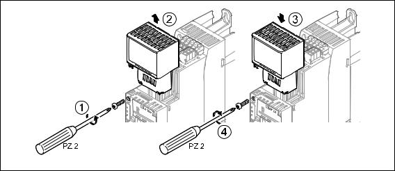
5.1.1Mounting for 0.25 kW and 0.37 kW standard devices
E84YCPM002D |
[5-1] Mounting for 0.25 kW and 0.37 kW standard devices
Mounting steps
1.Pry the cover out of the MCI slot using a screwdriver and remove it (1, 2).
2.Loosen the securing screw for the communication module on the standard device (3).
3.Insert the communication module into the MCI slot of the standard device (4).
4.Fasten the securing screw (5).
Lenze · E84AYCPM communication module (PROFIBUS®) · Communication Manual · DMS 5.0 EN · 11/2012 · TD17 |
22 |
5 Installation
5.1Mechanical installation
_ _ _ _ _ _ _ _ _ _ _ _ _ _ _ _ _ _ _ _ _ _ _ _ _ _ _ _ _ _ _ _ _ _ _ _ _ _ _ _ _ _ _ _ _ _ _ _ _ _ _ _ _ _ _ _ _ _ _ _ _ _ _ _
5.1.2Mounting for standard devices of 0.55 kW and more
E84YCPM002A
[5-2] Mounting for standard devices of 0.55 kW and more
Mounting steps
1.Slightly press on the area indicated in the illustration at the top of the cover for the standard device's MCI slot (1).
2.Tilt the cover forward and remove it from the standard device (2).
3.Loosen the securing screw for the communication module on the standard device (3).
4.Insert the communication module into the MCI slot of the standard device (4).
5.Fasten the securing screw (5).
23 |
Lenze · E84AYCPM communication module (PROFIBUS®) · Communication Manual · DMS 5.0 EN · 11/2012 · TD17 |
5 Installation
5.1Mechanical installation
_ _ _ _ _ _ _ _ _ _ _ _ _ _ _ _ _ _ _ _ _ _ _ _ _ _ _ _ _ _ _ _ _ _ _ _ _ _ _ _ _ _ _ _ _ _ _ _ _ _ _ _ _ _ _ _ _ _ _ _ _ _ _ _
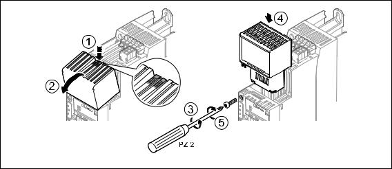
5.1.3Replacing the communication module
E84YCPM002B |
[5-3] Replacing the communication module
Mounting steps
1.Loosen the securing screw for the communication module on the standard device (1).
2.Remove the communication module from the MCI slot of the standard device (2).
3.Insert the new communication module into the MCI slot of the standard device (3).
4.Fasten the securing screw (4).
Lenze · E84AYCPM communication module (PROFIBUS®) · Communication Manual · DMS 5.0 EN · 11/2012 · TD17 |
24 |
5 Installation
5.2Electrical installation
_ _ _ _ _ _ _ _ _ _ _ _ _ _ _ _ _ _ _ _ _ _ _ _ _ _ _ _ _ _ _ _ _ _ _ _ _ _ _ _ _ _ _ _ _ _ _ _ _ _ _ _ _ _ _ _ _ _ _ _ _ _ _ _
5.2Electrical installation
Documentation for the standard device, control system, plant/machine
Observe the notes and wiring instructions given in the documentation.
5.2.1Network topology
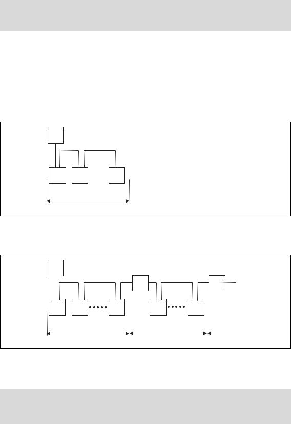
The following examples show two simple RS485 networks.
Every segment of the network must be terminated at both ends. The bus terminators of the PROFIBUS are marked with a "Z" in the below examples.
In the case of an RS485 network of only one segment, the PROFIBUS master (M) with the integrated bus terminator starts the segment while the bus terminating resistor in the connector of the last PROFIBUS station (S) must be activated.
M
Z
Z
S 
 S
S 


 S
S
1
E94YCPM012a
[5-4] RS485 network with one segment
An RS485 network consisting of several segments contains repeaters (R) for coupling the segments. The repeaters are provided with integrated bus terminating resistors.
M
|
Z |
|
|
|
|
|
|
|
|
Z |
R |
Z |
|
|
Z |
R |
Z |
|||||
|
|
|
|
|
|
|
|
|
|
|
|
|||||||||||
|
|
|
|
|
|
|
|
|
|
|
|
|
|
|
|
|
|
|
||||
|
|
|
|
|
|
|
|
|
|
|
|
|
|
|
|
|
|
|
|
|
|
|
|
|
|
|
|
|
|
Z |
|
|
|
|
|
|
|
|
|
|
|
|
|||
|
|
|
|
|
|
|
|
|
|
|
|
|
|
|
|
|
|
|
|
|
|
|
|
S |
S |
|
S |
|
|
|
|
|
S |
|
S |
|
|
|
|||||||
|
|
|
|
|
|
|
|
|
|
|
|
|
|
|
|
|
|
|
|
|
|
|
|
|
|
|
|
1 |
|
|
|
|
|
|
2 |
|
|
|
3 |
||||||
|
|
|
|
|
|
|
|
|
|
|
|
|
|
|
|
|
|
|
|
|
|
|
|
|
|
|
|
|
|
|
|
|
|
|
|
|
|
|
|
|
|
|
|
|
|
E94YCPM012b
[5-5] RS485 network with a repeater
If no repeater is to be used at the end of the segment, the bus terminating resistor must be activated in the connector of the last device. The bus termination is supplied by the station itself.
Stop!
The bus terminator must always be supplied. Otherwise, the bus can get unstable.
25 |
Lenze · E84AYCPM communication module (PROFIBUS®) · Communication Manual · DMS 5.0 EN · 11/2012 · TD17 |
5 Installation
5.2Electrical installation
_ _ _ _ _ _ _ _ _ _ _ _ _ _ _ _ _ _ _ _ _ _ _ _ _ _ _ _ _ _ _ _ _ _ _ _ _ _ _ _ _ _ _ _ _ _ _ _ _ _ _ _ _ _ _ _ _ _ _ _ _ _ _ _
Activating the bus terminating resistor ( 27)
Number of stations
|
|
|
|
|
|
|
|
|
|
|
|
|
|
|
|
|
|
|
|
|
|
|
M |
|
|
|
|
|
|
|
|
|
|
|
|
|
|
|
|
|
|
|
|
|
|
|
|
|
|
|
|
|
|
|
|
|
|
|
|
|
|
|
|
|
|
|
|
|
|
|
|
|
R |
|
|
|
|
|
|
R |
|
||
|
|
|
|
|
|
|
|
|
|
|
|
|
|
|
|
|||||
|
|
|
|
|
|
|
|
|
|
|
|
|
|
|
|
|
|
|
|
|
|
|
|
|
|
|
|
|
|
|
|
|
|
|
|
|
|
|
|
|
|
|
|
S |
|
S |
|
|
S |
|
|
|
S |
|
S |
|
|
|
|
|
|
|
|
|
|
|
|
|
|
|
|
|
|
|
|
|
|
|
|
|
|
|
|
|
|
|
|
|
|
1 |
|
|
|
|
2 |
|
|
|
3 |
|
||||
|
|
|
|
|
|
|
|
|
|
|
|
|
|
|
|
|
|
|
|
2133PFB004 |
|
|
|
|
|
|
|
|
|
|
|
|
|
|
|
|
|
|
|
|
|
|
|
|
|
|
|
|
|
|
|
|
|
|
|
|
|
|
|
|
|
|
[5-6] Number of stations |
|
|
|
|
|
|
|
|
|
|
|
|
|
|
|
|
|
|||
|
|
|
|
|
|
|
|
|
|
|
|
|
||||||||
|
Segment |
|
|
Master (M) |
|
|
Slave (S) |
|
|
|
|
Repeater (R) |
||||||||
|
1 |
|
|
|
|
1 |
|
|
|
|
|
31 |
|
|
|
|
- |
|||
|
|
|
|
|
|
|
|
|
|
|
|
|
|
|
|
|||||
|
|
|
|
|
|
2 |
|
|
|
|
|
30 |
|
|
|
|
- |
|||
|
2 |
|
|
|
|
- |
|
|
|
|
|
30 |
|
|
|
|
1 |
|||
|
3 |
|
|
|
|
- |
|
|
|
|
|
30 |
|
|
|
|
1 |
|||
|
|
|
|
|
|
|
|
|
|
|
|
|
|
|
|
|
|
|
|
|
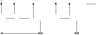
Tip!
Repeaters do not have a station address. When calculating the maximum number of stations, they reduce the number of stations by 1 on each side of the segment.
Repeaters can be used to build up line and tree topologies. The maximum total bus system expansion depends on ...
•the baud rate used;
•the number of repeaters used.
Lenze · E84AYCPM communication module (PROFIBUS®) · Communication Manual · DMS 5.0 EN · 11/2012 · TD17 |
26 |

5 Installation
5.3Activating the bus terminating resistor
_ _ _ _ _ _ _ _ _ _ _ _ _ _ _ _ _ _ _ _ _ _ _ _ _ _ _ _ _ _ _ _ _ _ _ _ _ _ _ _ _ _ _ _ _ _ _ _ _ _ _ _ _ _ _ _ _ _ _ _ _ _ _ _
5.3Activating the bus terminating resistor
The PROFIBUS must be terminated by a bus terminating resistor at the first and last physical bus station.
The bus terminating resistor in the bus connector of the bus cable is activated by means of a switch.
PROFIBUS cables with integrated bus terminating resistor are offered by several cable manufacturers.
Note!
If you want to disconnect individual bus stations, ensure that the bus terminators at the cable ends remain active.
Please observe that the bus termination is not active any longer if ...
•the bus connector has been disconnected;
•the voltage supply of the Inverter Drive 8400 has been switched off.
27 |
Lenze · E84AYCPM communication module (PROFIBUS®) · Communication Manual · DMS 5.0 EN · 11/2012 · TD17 |

5 Installation
5.3Activating the bus terminating resistor
_ _ _ _ _ _ _ _ _ _ _ _ _ _ _ _ _ _ _ _ _ _ _ _ _ _ _ _ _ _ _ _ _ _ _ _ _ _ _ _ _ _ _ _ _ _ _ _ _ _ _ _ _ _ _ _ _ _ _ _ _ _ _ _
5.3.1Bus cable specification
Note!
Only use cables which meet the listed specifications of the PROFIBUS user organisation.
Area |
Values |
Cable resistance |
135 ... 165 Ω/km, (f = 3 ... 20 MHz) |
Capacitance per unit length |
≤ 30 nF/km |
Loop resistance |
< 110 Ω/km |
Core diameter |
> 0.64 mm |
Core cross-section |
> 0.34 mm2 |
Cores |
Twisted in pairs, insulated and shielded |
|
|
Bus cable length
The length of the bus cable depends on the baud rate and cable type used. The data in the following table applies to PROFIBUS cables of "FC-Standard Cable" cable type .
Baud rate |
Length |
9.6 ... 93.75 kbps |
1200 m |
187.5 kbps |
1000 m |
500 kbps |
400 m |
1500 kbps |
200 m |
3000 ... 12000 kbps |
100 m |
|
|
Note!
The baud rate depending of the data volume, cycle time and number of stations should only be selected as high as required for the application.
Tip!
We recommend taking the use of optical fibres into consideration for high baud rates. Advantages of optical fibres:
•External electromagnetic interferences have no effect on the transmission path.
•Bus lengths of several kilometres are also possible with higher baud rates.
•The bus length is ...
•independent of the baud rate;
•dependent on the optical fibre used.
Lenze · E84AYCPM communication module (PROFIBUS®) · Communication Manual · DMS 5.0 EN · 11/2012 · TD17 |
28 |

5 Installation
5.3Activating the bus terminating resistor
_ _ _ _ _ _ _ _ _ _ _ _ _ _ _ _ _ _ _ _ _ _ _ _ _ _ _ _ _ _ _ _ _ _ _ _ _ _ _ _ _ _ _ _ _ _ _ _ _ _ _ _ _ _ _ _ _ _ _ _ _ _ _ _
5.3.2PROFIBUS connection
The 9-pole Sub-D socket X201 serves to connect the communication module to the bus system.
Assignment of the 9-pin Sub-D socket X201
View |
|
Pin |
Assignment |
Description |
|
1 |
6 |
1 |
Not assigned |
- |
|
|
|
|
|||
|
|
2 |
Not assigned |
- |
|
|
|
|
|
|
|
|
|
3 |
RxD/TxD-P |
Data line B (received data/transmitted data, plus) |
|
|
|
|
|
|
|
|
|
4 |
RTS |
Request To Send (received data/transmitted data, no |
|
|
|
|
|
differential signal) |
|
5 |
9 |
|
|
|
|
5 |
M5V2 |
Data ground (ground to 5 V) |
|||
|
|||||
|
|
||||
|
|
|
|
|
|
|
|
6 |
P5V2 |
5 V DC / 30 mA (bus termination) |
|
|
|
|
|
|
|
|
|
7 |
Not assigned |
- |
|
|
|
|
|
|
|
|
|
8 |
RxD/TxD-N |
Data line A (received data/transmitted data, minus) |
|
|
|
|
|
|
|
|
|
9 |
Not assigned |
- |
|
|
|
|
|
|
29 |
Lenze · E84AYCPM communication module (PROFIBUS®) · Communication Manual · DMS 5.0 EN · 11/2012 · TD17 |

6 Commissioning
6.1Before initial switch-on
_ _ _ _ _ _ _ _ _ _ _ _ _ _ _ _ _ _ _ _ _ _ _ _ _ _ _ _ _ _ _ _ _ _ _ _ _ _ _ _ _ _ _ _ _ _ _ _ _ _ _ _ _ _ _ _ _ _ _ _ _ _ _ _
6 Commissioning
During commissioning, plant-specific data such as motor parameters, operating parameters, responses, and parameters for fieldbus communication are defined for the inverter. Lenze devices use codes for this purpose.
The codes of the inverter and for communication are saved to the memory module in a non-volatile data set.
In addition, there are codes for diagnosing and monitoring the stations. Parameter reference ( 95)
6.1Before initial switch-on
Stop!
Before switching on the inverter for the first time, check ...
•the entire wiring for completeness, short circuit and earth fault.
•whether the bus system is terminated by means of a bus terminating resistor at the first and last physical bus station.
Activating the bus terminating resistor ( 27)
Lenze · E84AYCPM communication module (PROFIBUS®) · Communication Manual · DMS 5.0 EN · 11/2012 · TD17 |
30 |
Loading...