


MS6000 MKII
Table of contents
 Loading...
Konica Minolta MS6000 MKII, PS3000PR, MS7000, PS3000, MS7000 MKII Manual
...
Installation and User’s Guide
For
Konica Minolta Business Solutions’
TWAIN Driver V.5.0.1.7b &
Overlay Manager Software
September 10, 2004

Section 1 - Overview & Hardware Installation....................................................... 2
HARDWARE INSTALLATION...................................................................................................... 2
3
4
4
4
7
.8
16
16
21
23
30
32
33
42
42
45
46
50
50
52
54
55
Section 2 –Software Installation..............................................................................
THE TWAIN DRIVER USER INTERFACES ...............................................................................
Section 3 - The MS 6000 TWAIN Driver User’s Guide.........................................
THE MS 6000 SCANNER SETUP USER INTERFACE ..................................................................
BATCH SCAN MODE..................................................................................................................
MARS CONTROLLER BUTTONS .............................................................................................
Section 4 -The MS 7000 TWAIN Driver User’s Guide........................................
THE MS 7000 SCANNER SETUP USER INTERFACE ................................................................
BATCH SCAN MODE................................................................................................................
MARS CONTROLLER BUTTONS ............................................................................................
Section 5 - TWAIN Configuration Utility & Status Window...............................
Section 6 – Overlay Manager User’s Guide..........................................................
USING THE OVERLAY MANAGER SOFTWARE........................................................................
Section 6 -The PS 7000 TWAIN Driver User’s Guide.........................................
THE PS 7000 SCANNER SETUP USER INTERFACE..................................................................
BATCH SCAN MODE................................................................................................................
BATCH SCANNING IN ARIEL 3.0.............................................................................................
Section 7 -The PS 3000 TWAIN Driver User’s Guide.........................................
THE PS 3000 SCANNER SETUP USER INTERFACE..................................................................
SCAN SETTINGS:.....................................................................................................................
BATCH SCAN MODE –.............................................................................................................
BATCH SCANNING IN ARIEL 3.0.............................................................................................
1
Section 1 - Overview & Hardware Installation
Thank you for purchasing a Minolta TWAIN-supported Microform or Publication Scanner. This version of the
Minolta TWAIN driver supports the following Minolta scanners:
2
• MS 3000 Microform Scanner
• MS 7000 Microform Scanner
• MS 2000 Microform Scanner
• PS 3000 Publication Scanner
• MS 6000 Microform Scanner
• PS 7000 Publication Scanner
This TWAIN driver and Overlay Manager Software may be freely copied and distributed for
use with Minolta Scanners sold in the United States of America or Canada. JFL Peripheral
Solutions Inc. of Ottawa, Ontario, Canada developed the TWAIN driver. For information
regarding distribution outside of the United States of America or Canada, please contact them
at:
JFL Peripheral Solutions
1007 Merivale Road, Suite 101
Ottawa, Ontario
K1Z 6A6
Voice: (613) 728-2521 x206
Fax: (613) 728-4459
Email: info@jflinc.com
Hardware Installation
The Minolta scanners utilize industry standard 50-pin, male SCSI-1 (MS 3000, MS 2000, and
PS 3000) and SCSI-2 (MS 6000 and MS 7000) connectors. The PS 7000 uses a proprietary
cable sold only through Konica Minolta Business Solutions and is a 5-pin Mini Centronics on
the scanner end and a 50-pin HD SCSI-2 on the PC side. You will need to supply a standard
SCSI interface card for the PC as well as a SCSI cable. We have tested a wide range of SCSI
boards and have found that nearly all Adaptec or Adaptec-compatible boards will run fine. We
also recommend installing the latest version of Adaptec’s ASPI drivers.
If you have any connection errors please check for system conflicts first. If you are still unable
to resolve any hardware conflicts or cannot get your scanner to be recognized please contact
your local Minolta dealer. When calling for technical support please make sure to have the
driver version numbers and your system configuration information available.
A Note about Integrating Konica Minolta Business Solutions Scanners
For those customers who wish to directly integrate one of the TWAIN supported Minolta
scanner listed above with their own software, we recommend contacting JFL Peripheral
Solutions, Inc. to obtain their ObjectTWAIN
®
developer’s toolkit. This toolkit has all the
necessary tools to fully integrate our supported scanners.
Note: All sample scanned images in this guide are actual microfilm
scans and were enlarged by 200-250% to show detail at the pixel
level. They do not represent 1-to-1 resolutions.
stallation
lutions TWAIN driver and Overlay Manager software are
s
®
95, 98, NT 4.0, 2000, ME, and XP. To install either or
nch the Minsetup.exe file.
After agreeing to the software license and selecting the desired install directories, you will be
asked to choose which of the two components you would like to install.
TWAIN Data Source: Install the TWAIN data source when using the MS 2000, MS 3000,
PS 3000, PS 7000, MS 6000 or MS 7000 as PC-connected scanners. Please note that in
order to use the TWAIN data sources with the MS 6000 you need to have the optional PC-
upgrade kit installed. The PS 7000 requires you to purchase the PC Interface Kit. The
TWAIN data sources utilize Version 1.9 of the TWAIN specification and incorporate all
the scanning features of the supported scanners.
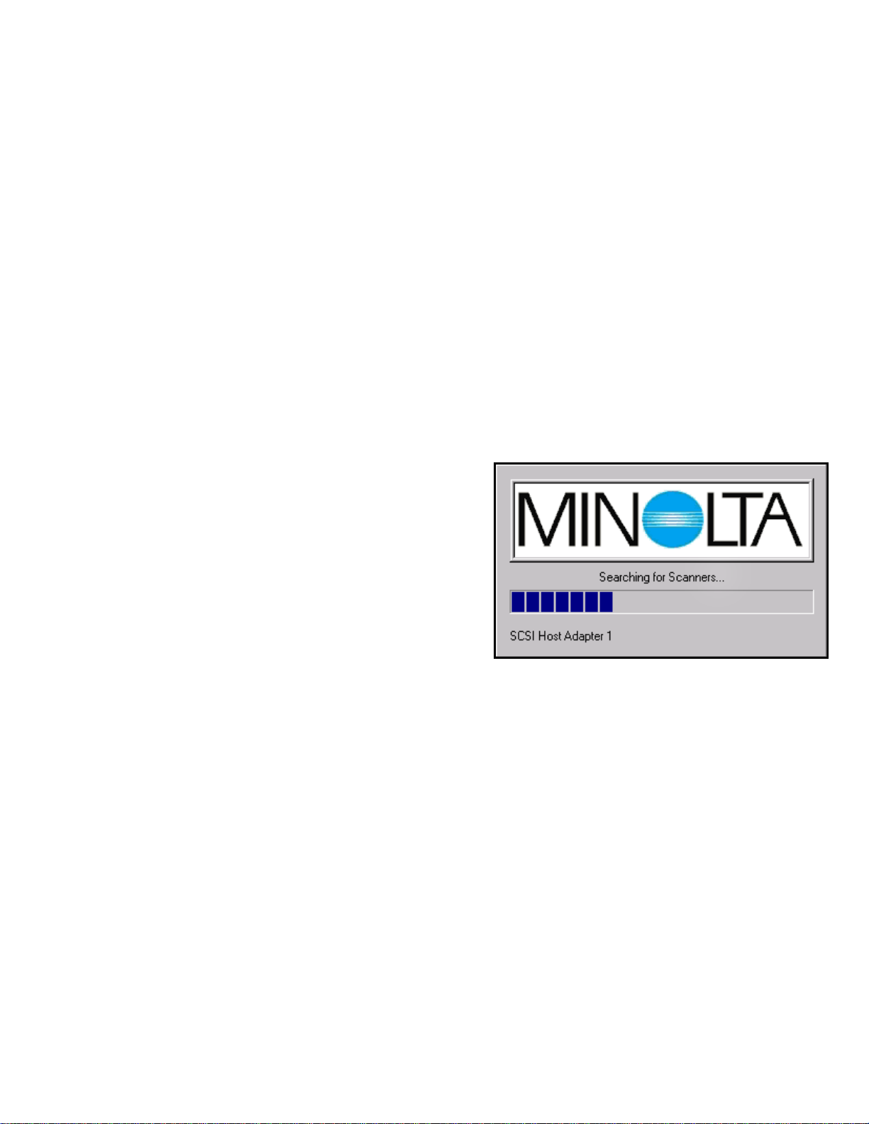
When installing the TWAIN Data source the installation procedure will automatically
launch the KMBS TWAIN configuration
utility.
This utility will scan your SCSI buses and
automatically detect any of the supported
Minolta scanners attached to your system. It
will then install the needed drivers (data
sources) associated with those scanners. Once
the configuration utility has completed its scan
and installs, it will launch a status window
showing all the connected Minolta hardware
and all installed drivers/data sources (see Section 5 for more details).
Make any necessary settings in the Status Window and close it out. You are now ready to
begin scanning. Since software packages vary, please check your application software for
instructions on how to acquire a scanned image using a TWAIN driver.
A new feature of the updated driver is allowing you to choose to not install the software
memory manager. Although this is still required for non Enhanced SCSI, it can be skipped
on current models thereby preventing possible memory conflicts and admin-right issues.
Overlay Manager: Install the Overlay Manager when using the MS 6000 or MS 7000 in
combination with the MSP 3000 laser printer. The Overlay software allows you to create and
add a bitmap to any prints made from the MSP 3000 laser printer and the MS 6000 or 7000. In
order to utilize overlays with the MS 6000 or MS 7000 scanner you must ensure that the
latest version of firmware (25G003 or higher) is installed in your scanner. If you are
unsure of your firmware version or need to upgrade please contact your authorized Minolta
dealer.
Section 2 –Software In
The Konica Minolta Business So
compatible with Microsoft Window
both of these applications simply lau

The TWAIN Driver User Interfaces
When developing the TWAIN drivers for Minolta’s scanners we tried to keep a consistent l
and feel across all models. Since each scanner has unique functions and features the drivers do
vary from model to model. In the following sections we walk through the MS 6000 and MS
00
ook
0 TWAIN drivers and explain what their various features and functions are as well as how
work with th ile working with a driver, you want a quick definition
of a given feature you can always left-click the mouse while holding the pointer over the
feature in que ll window with information on that feature’s
functionality. Users of the MS 2000 and MS 3000 will find that nearly all the features of the
scanner’s TWA
7000 User’s G
Nearly all sele ers are “sticky” and settings will remain unchanged if
e ed. Driver settings always take precedence over the scanner’s
er case “c”. Once the
®
, Photoshop
®
, etc.) are
nstructed to a w. This is
your User Inte o configure
the MS 6000 f the controls
anel of the scanner and can be
nel is also used for direct printing, some of
e nomenclature used between the driver and front panel may differ. Please see the
7
to em. Remember that if, wh
stion. This will launch a sma
IN drivers are covered in the enclosed MS 6000 and MS 7000, PS 3000 and PS
uides as well.
ctions in the TWAIN driv
the driver is closed and reop n
front panel settings.
Section 3 - The MS 6000 TWAIN Driver User’s Guide
The MS 6000 is KMBS’ low-to-mid volume Microform scanner. It is very similar to its
predecessor, the MS 2000, however it offers many new features. In order to scan-to-file with
e MS 6000 the user must ensure that the optional PC interface kit is installed and the th
front panel of the MS 6000 is set to operate in PC mode. The scanner can be configured for
PC mode by pressing the clear/Shift key and the multiple print/PC keys at the same time.
These two keys are adjacent to each other and are located just above the Start button on the
front panel.
When in PC mode the scanner will display a capital “P” and a low
TWAIN driver is launched the small “c” on the scanner’s LED will change to a capital “C” to
indicate that proper communication exists between the scanner and driver.
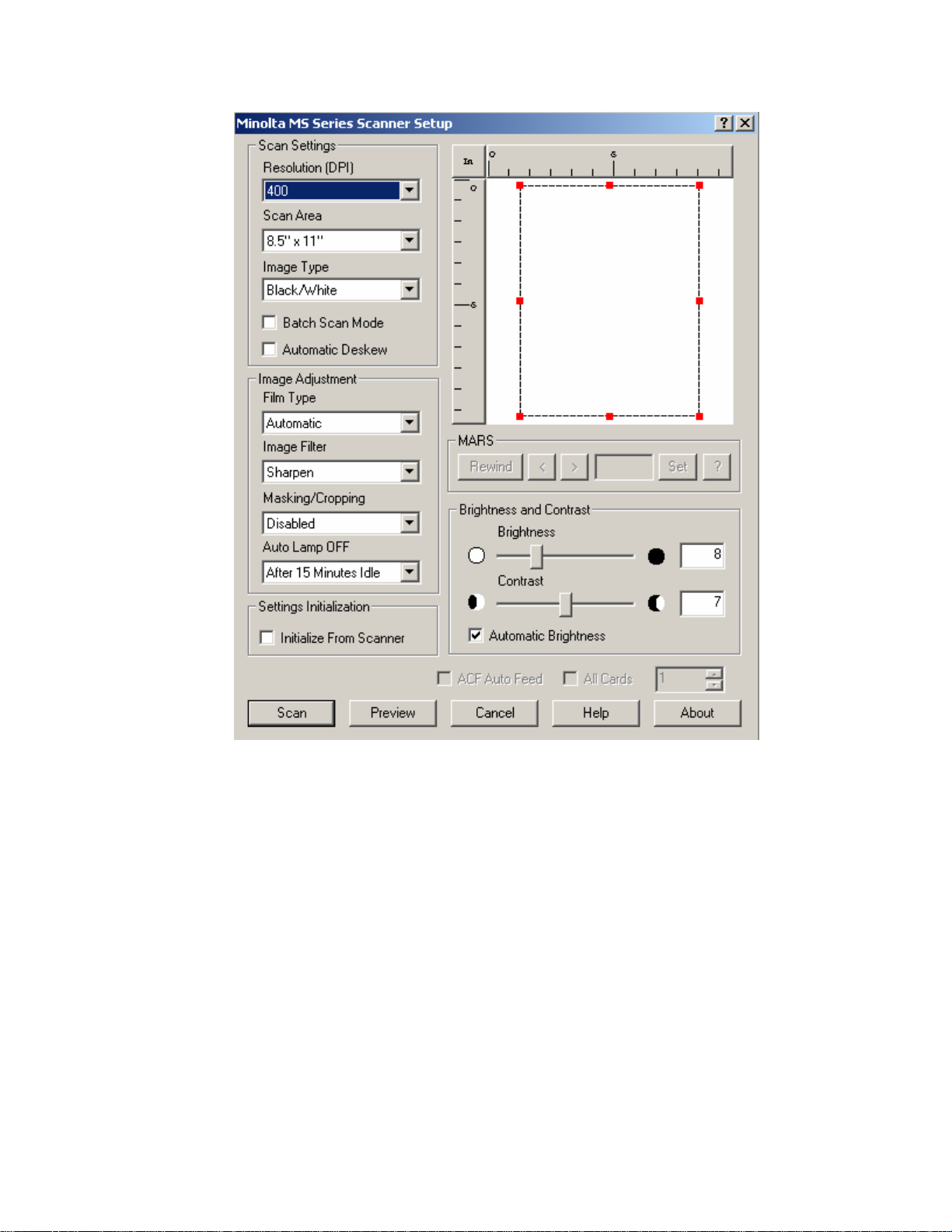
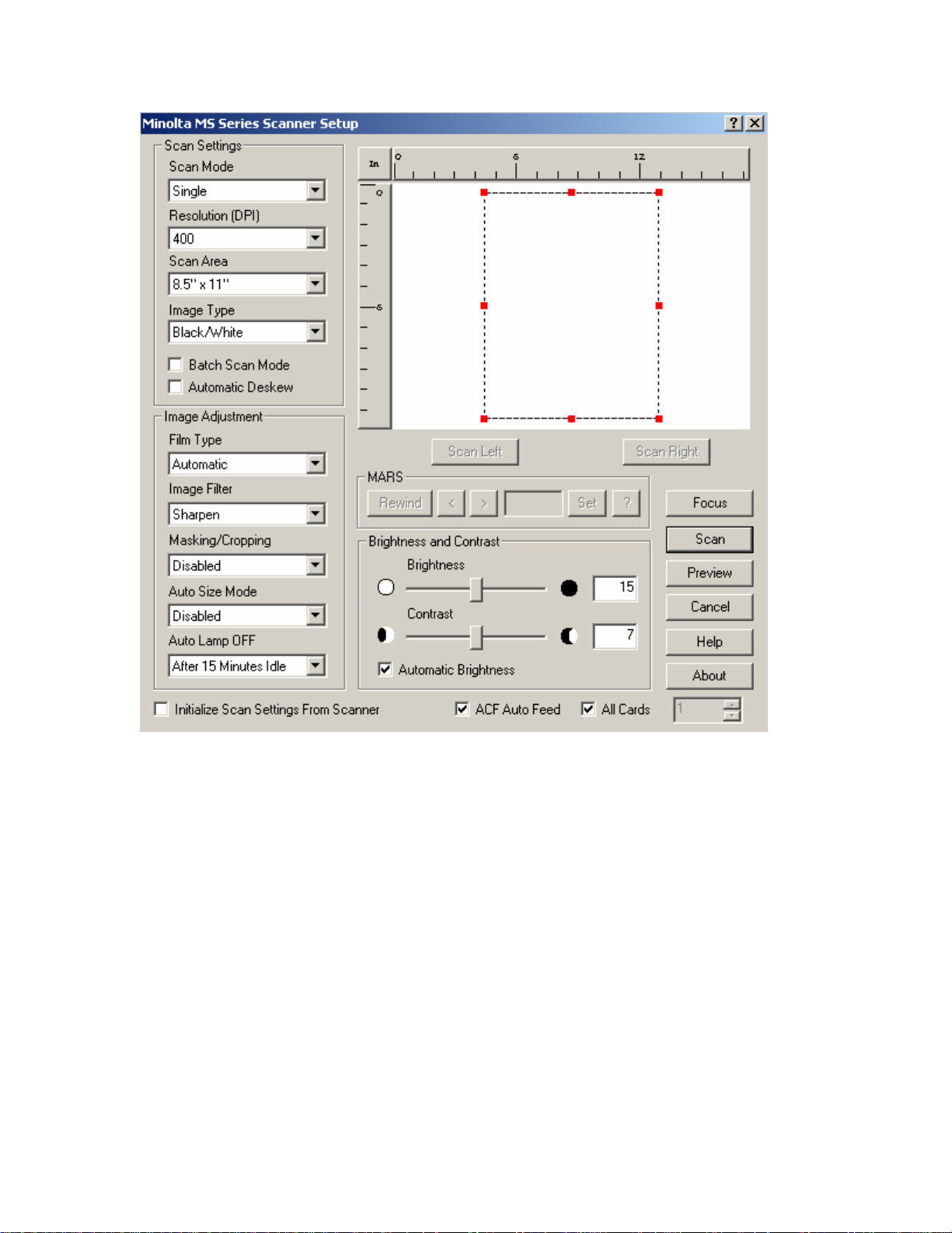
The MS 6000 Scanner Setup User Interface
hen most off-the-shelf software applications (such as Adobe AcrobatW
i cquire an image they will launch the MS 6000 Scanner Setup Windo
rface (UI) for communicating to the TWAIN driver. It allows you t
as necessary prior to scanning. Please keep in mind that many o
he front pfound in the driver’s UI are also duplicated on t
controlled from the scanner itself. Since the front pa
th
appropriate sections below to determine if UI settings are duplicated on the front panel and to
determine which buttons duplicate those commands.
Preview
Window
en changing settings via the scanner’s front panel, the driver UI will update in real-time (aWh s
long as the driver is currently launched). While the scanner is busy executing a scan the front
Resolution (DPI) – This drop-down box allows you to select the resolution at which the
ing software. The resolution is measured in dots
panel LED display will show a flashing “PC” and the front panel will be locked. When the
display stops flashing, the scanner’s control panel is once again active.
Scan Settings
The Scan Settings section allows you to define three key elements of the scanner’s settings.
They are:
scanner will deliver data to the scann
per inch or DPI. Available settings for the MS 6000 are 200, 300, 400, 600 and 800
DPI. Higher DPI settings will result in better quality scans but will result in longer
scanning and data transfer times as well as larger file sizes. If using the front panel of
the MS 6000, the resolution can be selected by pressing the Clear/Shift key and the
Print Mode/Resolution keys at the same time. Each subsequent press will cycle the
resolution setting between 8H, 6H, 4H, 3H and 2H.
Note: The optical resolution of the scanner is 400 DPI. All other
resolutions are derived from on-board interpolation or reduction
algorithms.
Paper Size – This drop-down box allows you to select the actual Scan Area captured by
the MS 6000.
The driver supports a wide range of standard U.S. and European sizes.
The scan area selected will be reflected in the Preview Window through the use of a
unique
selected
via the front panel of the MS 6000; however, the optional Manual Masking Kit
es:
dashed box. If desired, you can also select the custom setting and define any
scan area within the 12” x 12” window. Pre-configured paper sizes cannot be
provides functionality for defining a custom scan area. (See the Preview Window
section for more information).
Image Type – This drop-down box lets you define the bit-depth of the image. If the
optional grayscale kit is not installed, you will only have the option of selecting
Black/White. If the optional grayscale kit is installed then you have the following two
choic
Black/White – This will cause all
images delivered to the PC to have a
depth of 1-bit. As a result all pixels
will be either black or white. The
scanner will threshold the image and
perform a dithering algorithm
(see the Halftone setting for more information on setting dithers and halftones).
Grayscale – This setting will cause
all images to be delivered to the PC
to have a bit-depth of 8. This will
result in images with 256 possible
shades of gray.
Note: In order to utilize grayscale with the MS 6000 it will be
necessary to purchase and install the optional grayscale kit.
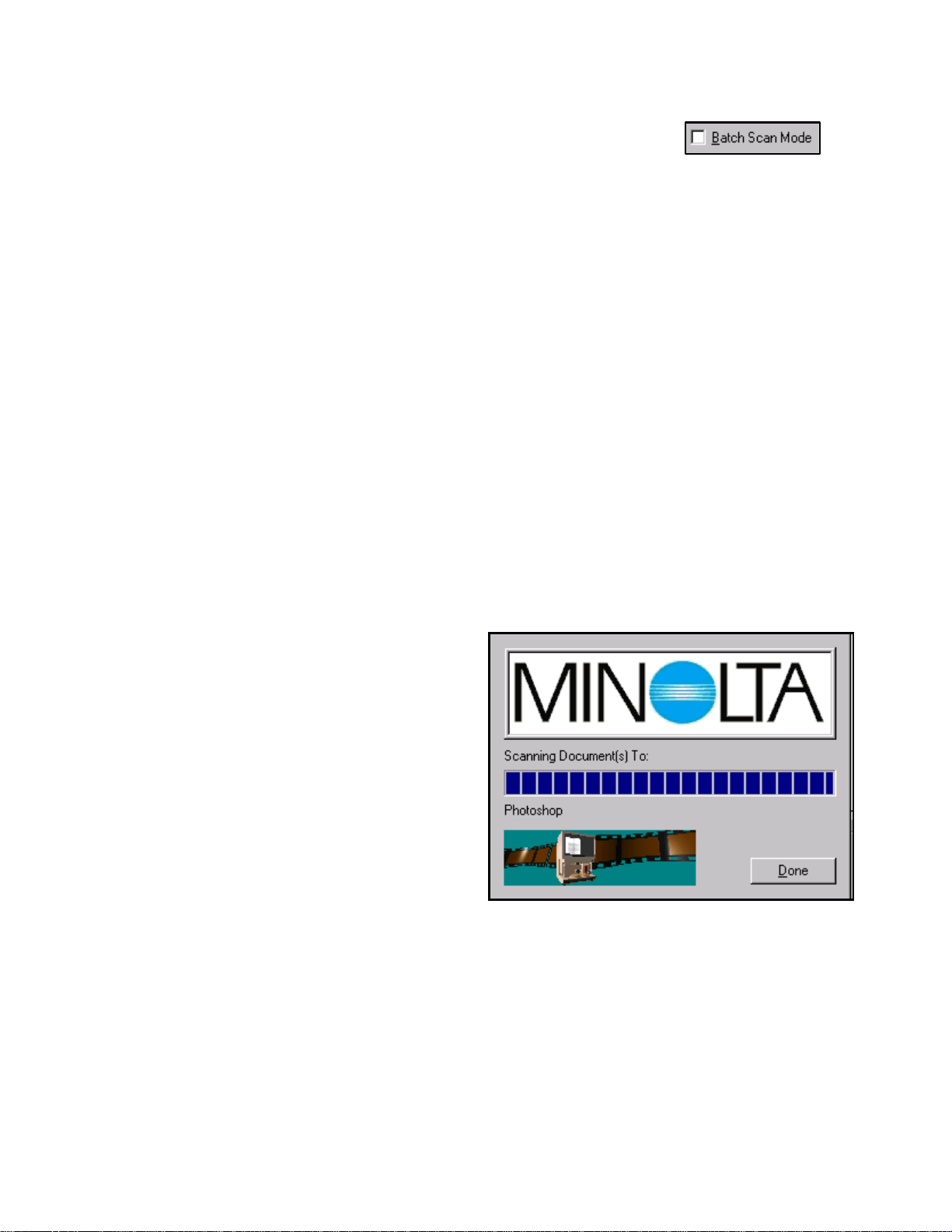
Batch Scan Mode
The Batch Scan Mode might arguably be the most useful feature of
the Minolta TWAIN driver. With most application software, the TWAIN driver UI is launched
when an Import or Scan command is given. Typically the driver will then close after a scan is
completed. When the Batch Scan Mode selection box is checked it will cause the driver to
remain open and will place a Done button in the File Transfer Status Window.
While the File Transfer Status Window is displayed you can continue to initiate scans and
make setting changes from the front panel of the MS 6000. Each scan will be delivered to the
application and stored in the computer’s available memory. While performing a batch scan,
you may not be able to view completed scanned images – this is normal. When the Done
button is pressed, the Status Window and Driver UI will close and all image data will be
displayed in the scanning application.
Note: Images scanned via the Batch Scanning Mode are not permanently stored but rather kept
in temporary memory by the application software. Therefore the number of scans that can be
stored will be dependent on image file sizes, the application itself as well as available system
memory.
Batch Scanning in Ariel 3.0
Ariel 3.0 adds support for TWAIN scanning. Because Ariel is designed for Automatic
Document Feeders (ADFs) batch scanning with the Minolta Scanners can be tricky. In order
to perform batch scanning with the MS
7000 make sure to:
1) Have Document/Scan
selected in the Ariel software
scanning window.
d now be able to scan multiple images from the front panel of the scanner. Click the
one b
Aut
to 3
then all deskewing will be done digitally. If there isn’t enough internal memory (typically
2) Click the More button in the
Ariel scanning window and then
make sure to have batch
scanning selected in the Minolta
TWAIN driver.
3) Click Ignore for any ADF
undetected errors you see.
You shoul
D utton in the File Transfer Status Window when finished.
omatic Deskew – Checking this box will cause the scanner to remove any skewing of up
0 degrees from scanned images. If enough internal memory is present on the scanner
whe
pris a the MS 6000’s front panel. If the
Automatic Image Rotation Kit is not installed, disabled or malfunctioning then this check
box will be
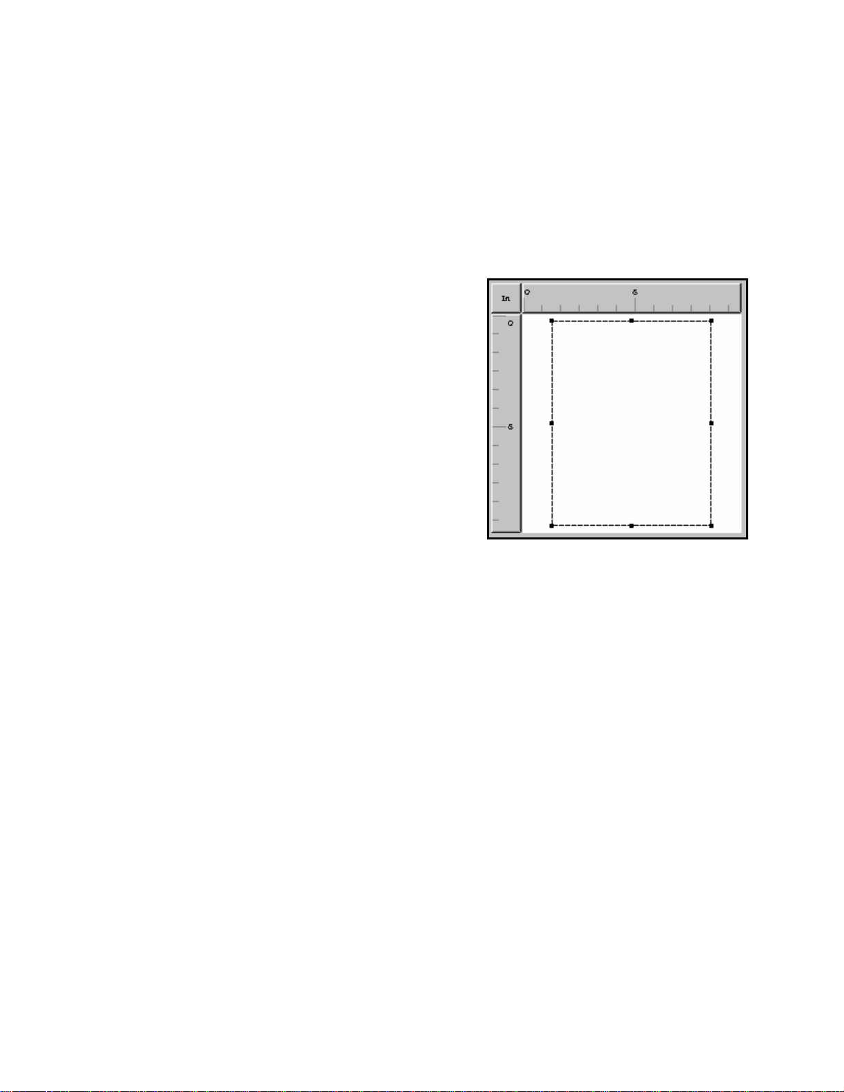
The Preview W
The preview window can be a very useful tool and provides a range of functionality that makes
workin
compon
Rul
the
left
ind
cen
Left clicking on this box of
mea
The
represents the entire 12” x 12” scan area of the
MS 6000. Within the preview window will be
an utlined
the actual area that the scanner is currently set to
capture. This outline can be changed and
manipulate d most common way is to select a preset
paper size Once a paper size is selected it will be
represented have more control over the scan area
can either resize the box or click and-drag a new rectangle. To resize the box first hover the
mouse over an edge or corner until the m
down the l r corner to the desired location. An even
easier way x and drag-and-drop the mouse to create
the desired ght click on the inside of the box and drag
the entire scan area anywhere in the 12” x 12” window.
When the masking kit is installed on your MS 6000, the LED buttons
along the edge will light to match the defined scan area in the preview window – even if
you drag and drop the preview area to another location! In addition, the lighted buttons can
be selected m of 4”
per side). T d displayed in the
preview window.
ARS Controller Buttons
hese series of buttons allow users to interface with a connected MARS 4 or MARS Mini-2
ontroller to control the movement and searching of blipped film. The controls within the
WAIN driver only offer minimal support for film movement and searching. There is no
pport in the TWAIN driver for automated batch-scanning of blipped film.
n no grayscale option is installed) then all deskewing will be done mechanically via the
m lens. Automatic deskewing can also be selected vi
grayed out.
indow
g with the MS 6000 easier and faster. The preview window is comprised of two key
ents:
ers – A horizontal ruler runs along the top of
window while a vertical ruler runs along the
edge. The box in the upper left corner
icates which form of measurement (inches or
timeters) is currently being used for the ruler.
will switch the form
surement between inches and centimeters.
Window – The preview window itself
o rectangle. This outline represents
d in a variety of ways. The easiest an
from the paper size drop-down box.
in the preview window. Users wishing to
ouse pointer changes to a resize tool then hold
eft mouse button and drag that edge o
is to simply right click outside the bo
size scan area. At any time you can ri
ptional manualo
manually from the front panel to define any custom scan area (minimu
he resultant defined area will be transferred to the driver an
M
T
c
T
su

Rewind – This button will cause the currently loaded roll of film to be completely rewound
and ejected.
This number will match the one shown on the MARS
unit’s LCD. In addition, users can enter a desired frame number in this window and hit the
set key. The MARS controller will then move the blipped film to the entered frame
? – Clicking this button will open a message window showing the current status of the
age Adjustment Controls
low you to make decisions that will alter the appearance of a
n down into the standard controls and the advanced
age Type mode set, this setting will cause the
> – This button will cause the currently loaded film to be advanced by one blip mark.
< – This button will cause the currently loaded film to be rewound by one blip mark.
Frame Number Box – The frame number box will display the current frame number as
reported by the MARS controller.
number.
Set – pressing the set key will move the blipped film to the entered frame number.
MARS controller.
When no MARS controller is connected to the PC these buttons will be grayed out and inactive
(as shown above).
Im
The Image Adjustment controls al
scanned image. These controls are broke
controls.
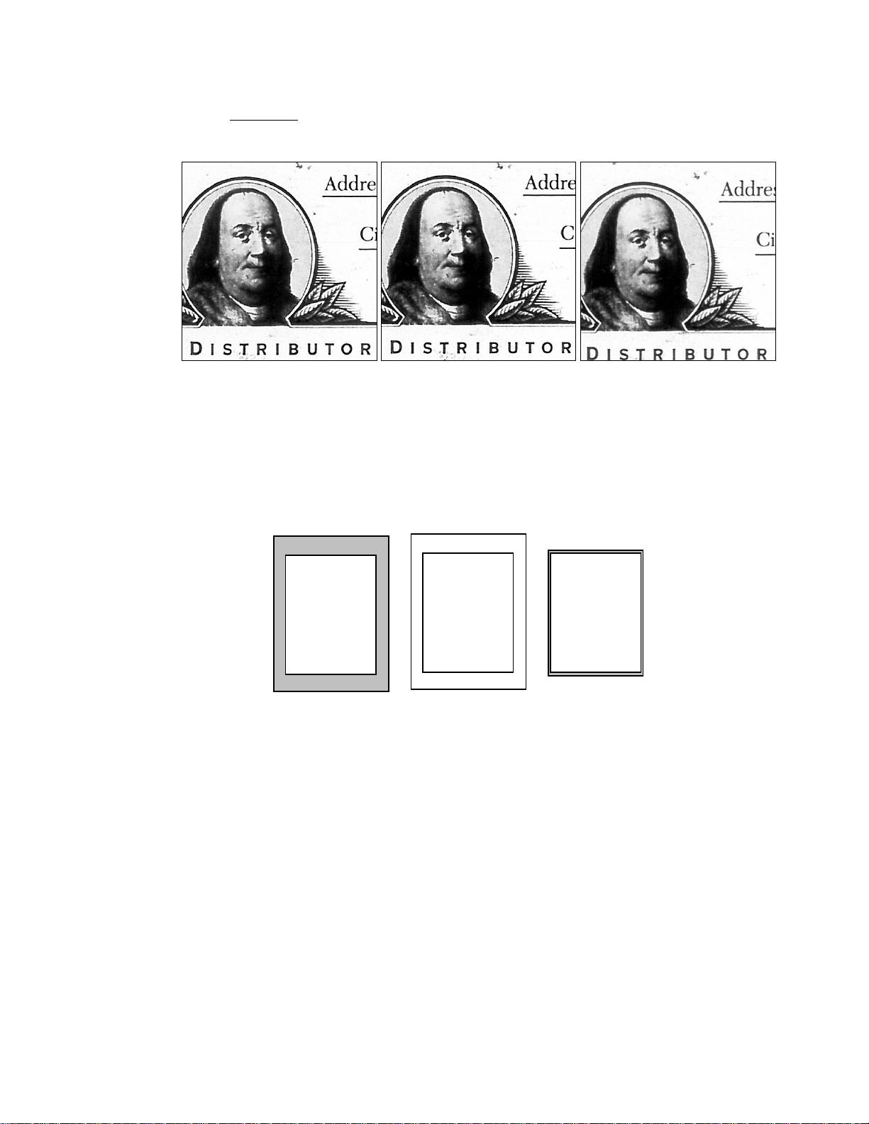
Original is Photo – Depending on the Im
scanned images to be affected as follows:
Black & White– Will tend to lighten the final image through a wider dithering process.
of the original but will typically over-lighten
This helps enhance the tonal quality
black/text areas.
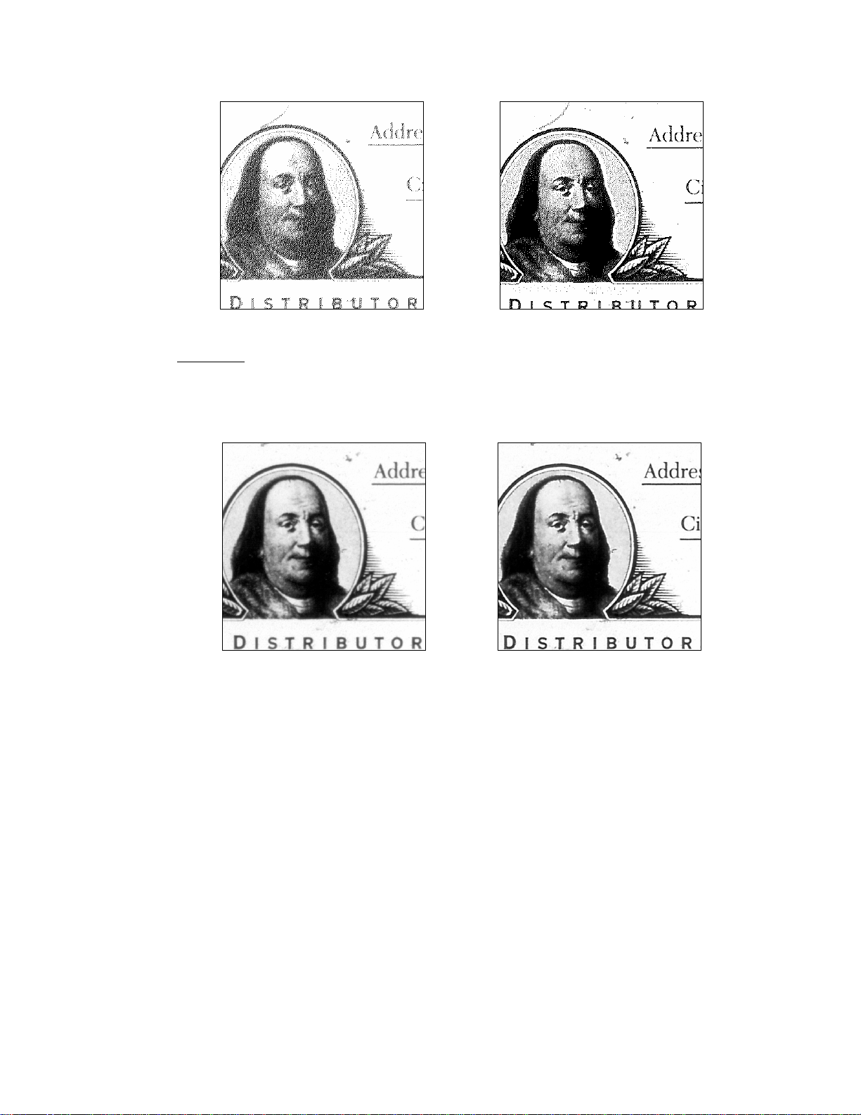
Original is Photo selected Original is photo unselected
Grayscale – Will apply a slight smoothing alg
to smooth rough edges and enhance photograp
images. This setting can be more useful
resolutions.
orithm to blur transitions. This will tend
hic areas, but will typically blur textual
when scanning tonal images at lower
Original is Photo selected Original is photo unselected
Film Type – Use this drop-down box to define the polarity of the film to be scanned.
Selecting positive will cause all images to be displayed as viewed on the front panel of the
MS 6000. Selecting negative will cause each pixel to be converted to its converse shade
.e. black to white, light gray to dark gray, etc.). Selecting auto will cause the scanner to (i
compare light areas to dark areas and make an intelligent guess based on image
composition as to which polarity film is loaded. Using the Film Type button on the front
panel of the MS 6000 can also change this setting.
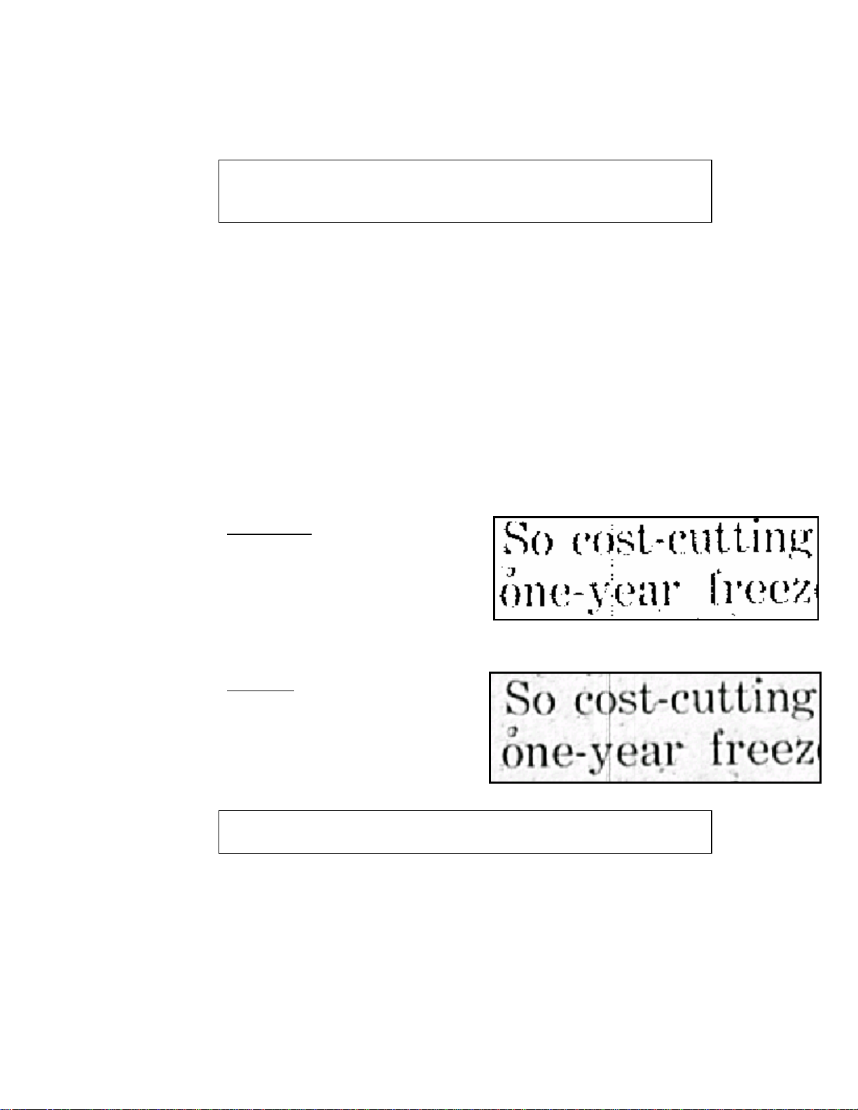
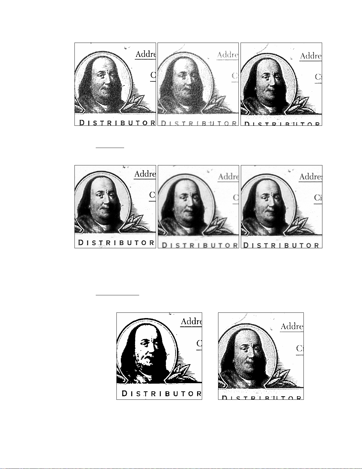
Image Filter – offers advanced algorithms for processing scanned images. Depending on
the image type selected the image filter has the following options.
None – An 8 bit grayscale image to be delivered as scanned. Black and white images
will lighten the final image through a wider dithering process; lighting is visually less than
the smooth mode.

Without
AFE
With
AFE
Sharpen – An 8-bit grayscale image, a strong sharpen algorithm for black and white
images will apply a straight threshold and standard dither.
Sharpen more – Only 8 bit grayscale images. The image goes through a sharpening
process that is slightly less pronounced than as sharpen
Enhanced dithering process that will result in better representation of tonal
ith
rop off the unnecessary border. Checking this
aller
sely related to Photo Mode and offers more advanced algorithms
ne – The “None” setting will cause an 8-bit grayscale image to be delivered as
ine Mode 1 – Depending on the Image Type mode set, this setting will cause the scanned
a
hite
Smooth –
areas within the image.
Line art – Only for black and white images. The resulting image will be displayed w
straight threshold and no dithering. This is an ideal setting for enhancing text or line art a
legibility.
Auto Frame Elimination – When scanning an area
larger than that needed for the current image, you may
ish to cw
box will cause the scanner to try and determine if there
any unnecessary border space and then remove the is
pixels associated with this unnecessary border.
Automatically removing the border will result in lesser
numbers of pixels being returned and hence, sm
file sizes. See the Automatic Masking Mode section below for more information on Frame
Elimination versus Automatic Masking.
Halftone – Halftone is clo
for processing a scanned image. Please note if Photo Mode is selected then the Halftone
drop-down box will be disabled. The Halftone box offers the following three selections:
No
captured and with black and white images will apply a straight threshold and standard
dither.
F
im ges to be affected as follows:
Black & W – Will lighten the final image through a wider dithering process.
This lightening is visually less than the Photo mode and can be thought of as a
mid-point setting between None and the “Original is photo” setting.
Mo elected i lected O ed Fine de 1 s Or riginal is photo not s
ginal is photo se elect
Grayscale – Will apply a sharpening algorithm. This will tend to make tonal
areas appear grainy while text will become crisper and better defined.
Fine Mode 1 selected Original is photo selected Original is photo not selected
Fine Mode 2 - Selecting this setting will cause the scanned images to be affected as
llows:
fo
Black & White
– Will cause the image to be displayed with a straight threshold
and no dithering. This is an ideal setting for enhancing text or line-art legibility.
Fine Mode 2 None
Grayscale – Will cause the image to undergo a sharpening process that is
slightly less pronounced than as with Fine Mode 1.
Fine Mode 2 Fine Mode 1 None
to m mage’s background.
mination (AFE) except that border
f removed. The number of pixels
AFE will crop borders and thus
Aut shut-off feature. This drop down
box all
before the scanner will turn the lamp off.
Init
beg stead of loading the settings saved from the previous
TWAIN sessio
Auto card feed
All Cards – This enabled option and AFC option to scan all cards in a single scan session.
Number of cards edit box – When AFC is enabled and all card option is disabled, use this area
to enter a number of cards that will be feed in a single scanning session.
Masking/Cropping – This setting will try to auto-detect black (or darkly shaded) areas
around the border of an image and convert these pixels
Please note that this feature is similar to Auto Frame Eli
pixels are converted to match the background instead o
captured will remain constant with this feature whereas
return smaller images.
o Lamp OFF – The MS 7000 supports an automatic lamp
atch the i
ows you to activate this feature as well as define the time interval of non-usage needed
No
Masking or
Frame
Elimination
Auto Masking
Auto Frame
Elimination
ialize scan settings from scanner – Retrieve the current scan settings from scanner at the
inning of a new TWAIN session in
n.
er – Automatically feed cards (AFC) during a scanning session

Brightness & Contrast Controls
This set of controls allows users to change the composition of the scanned image as detailed
below. Please note that when using the slider bars you may notice some slight lag or resistance
-- this is normal and is due to the bi-directional communication between the driver and
scanner.
Automatic Brightness – Check this box if you wish to have the scanner perform a prescan
and apply an appropriate brightness setting based on the detected original. Automatic
brightness will assume an original of normal exposure.
darker. When automatic brightness is selected this function will work as a small
adjustment
and 30. W ased on a
setting between 0 and 90.
In grayscale a lower brightness setting will result in each pixel being given a value closer
to white while a higher setting will cause each pixel to be given a value closer to black.
When scanning with Image Type set for black and white, a low brightness setting will
cause the thresholding process to result in more pixels being set to white while a higher
brightness will result in more pixels being set to black. Please note that all Brightness and
Contrast controls are applied prior to any Halftone or Photo settings. Brightness settings
can be adjusted using the front panel Auto, Darker and Lighter buttons.
Brightness – Changing these settings will cause the scanned image to appear lighter or
to the brightness applied by the AB function and the slider can be set between 0
hen AB is not selected this slider will apply an absolute brightness b
G/S Auto Brightness of 7 G/S Auto Brightness of 15 G/S Auto Brightness of 22
Contrast – The contrast settings extend from 0 to 14. Changing these settings will cause
the scanned image to either increase or decrease the range between dark and light areas. A
low contrast setting will result in each pixel being set to a value closer to the median (gray)
while a high contrast setting will result in each pixel being set to a value closer to its
absolute. In other words, light pixels get lighter and dark pixels get darker. A high contrast
can be desirable when trying to enhance dark objects on a less-than-white background or
when trying to enhance textual data in a grayscale image. Contrast cannot be adjusted from
the front panel.
G/S Contrast of 2 G/S Contrast of 7 G/S Contrast of 12
The Action Buttons
The Action buttons allow you to interact with the Driver User Interface to accomplish
important tasks or launch support windows. Here is a detailed description of what these
butt ns
o do:
Scan – Clicking the Scan button will cause the MS 6000 to initiate a scan using the
currently selected configuration. Scans can also be initiated by pressing the Start button on
the MS 6000’s front pa
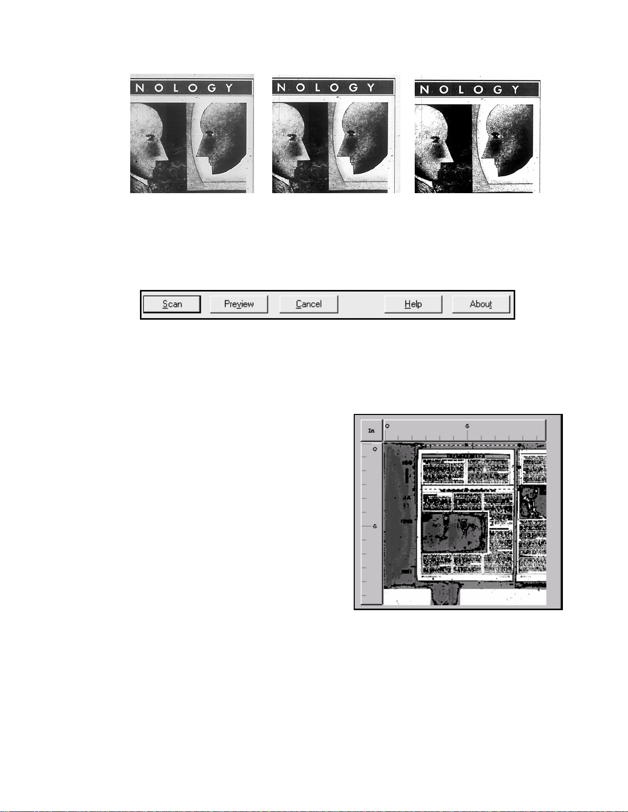
Preview – Clicking the Preview button will
cause the MS 6000 t a low-re
scan that will be displayed in the preview
window. This scanned data is not transferred to
the application. The preview function is very
useful for confirming scan settings and for
ed in the
e right the custom scan area has
file. This file contains
detailed information on working with the driver. Much of the information contained in this
guide can be found within the Help file.
nel. When operating the MS 6000 in Batch Scan Mode (see below)
this button will be disabled and all scans must be initialized via the front panel.
defining custom scans. To use previewing to
define a custom area, first click the Preview
utton; once an image has been plac
o perform solution
b
preview window just drag and drop or resize
the dashed lines to match the given portion of
the preview image you wish to capture. In the
example to th
been set to capture just the top article of the
page.
Cancel – Use the Cancel button to close out the driver window without initiating any scans.
Help – Clicking the Help button will launch the TWAIN driver help

About – Clicking this button will launch the About Dialog Box. This box contains
n 4 -The MS 7000 TWAIN Driver User’s Guide
The
pre
MS e MS 7000 is set to operate in PC
mo
Mu
loca
Wh
is l e scanners LED will change to a capital “C” to indicate that
pro
Th
Wh
acq
Inte
700 ntrols found in the
Driver’s UI are also duplicated on the front panel of the scanner and can be controlled from the
scanner itself. Since the front panel is mainly used for direct printing, some of the
nomenclature used between the driver and front panel may differ. Please see the appropriate
sections below to determine if UI settings are duplicated on the front panel and to determine
which buttons duplicate those commands.
important information including the current driver version number. This is the most
reliable means for determining which version of the driver you are running.
Sectio
MS 7000 is Minolta’s newest large-format Microform Scanner. It is very similar to its
decessor, the MS 3000, however it offers many new features. In order to scan with the
7000 the user must ensure that the front panel of th
de. The scanner can be configured for PC mode by pressing the Clear/Shift key and the
ltiple Print/PC keys at the same time. These two keys are adjacent to each other and are
ted just above the Start button on the front panel.
en in PC mode the scanner will display a capital “P” and a lower case “c”. Once the driver
unched the small “c” on tha
per communication exists between the scanner and driver.
e MS 7000 Scanner Setup User Interface
en a software application (such as Adobe Acrobat
®
, Photoshop
®
, etc.) is instructed to
uire an image, it will launch the MS 7000 Scanner Setup Window. This is your User
rface (UI) for communicating to the TWAIN driver. It allows you to configure the MS
0 as you like prior to scanning. Please keep in mind that many of the co
Wh e (as
lon scanner is busy executing a scan the front
pan he front panel will be locked. When the
display stops flashing, the scanner’s control panel is once again active.
Sca
The Scan Settings section allows you to define four key elements of the scanner’s settings.
The
Scan Mode – Because the MS 7000 has a large 12” x 17” scan area, it is capable of
Sin 000 driver will deliver one image as defined by
the scan area marker in the preview window (see below).
Preview
Window
en changing settings via the scanner’s front panel, the driver UI will update in real-tim
g as the driver is currently launched). While the
el LED display will show a flashing “PC” and t
n Settings
y are as follows:
actually capturing two 8 ½” x 11” side-by-side images with one scan. The Scan Mode
setting allows users to choose whether to have the MS 7000 deliver either one image or
a series of two images – one each for the left and rights sides. Your choices in the Scan
Mode drop-down box are:
gle – When in single scan mode, the MS 7
Loading...