


 Loading...
SERVICE MANUAL
Models
PZ-108/PZ-109
JANUARY 2004
CSM-PZ108/109
KONICA MINOLTA BUSINESS SOLUTIONS U.S.A., INC.

PZ-108/PZ-109 SERVICE MANUAL
JANUARY 2004
Used on Konica Models 7075/7085/7155/7165/7255/7272 FORCE 65/FORCE 75/FORCE 85

IMPORTANT NOTICE
Because of the possible hazards to an inexperienced person servicing this equipment, as well as the risk of damage to the equipment, Konica Minolta Business Solutions U.S.A., Inc. strongly recommends that all servicingbeperformedbyKonica-trainedservicetech- nicians only.
Changes may have been made to this equipment to improve its performance after this service manual was printed. Accordingly, Konica Minolta Business Solutions U.S.A., Inc., makes no representations or warranties, either expressed or implied, that the information contained in this service manual is complete or accurate. It is understood that the user of this manual must assume all risks or personal injury and/or damagetotheequipmentwhileservicingtheequipmentfor which this service manual is intended.
Corporate Publishing Department
© 2004, KONICA MINOLTA BUSINESS SOLUTIONS U.S.A., INC. All rights reserved.
Printed in U.S.A.

CONTENTS
CONTENTS
SAFETY AND IMPORTANT WARNING ITEMS
Refer to the 7155/7165/7255/7272 Service Manual
1.OUTLINE
PZ-108/PZ-109 PRODUCT SPECIFICATIONS ...... |
1-1 |
|
[1] |
Type ............................................................ |
1-1 |
[2] |
Functions .................................................... |
1-1 |
[3] |
Applicable Paper ......................................... |
1-2 |
[4] |
Panch/Z-folding Prohibition Paper .............. |
1-2 |
[5] |
Particulars of Machine ................................ |
1-2 |
[6] |
Maintenance and Life .................................. |
1-2 |
[7] |
Operating Environment ............................... |
1-2 |
CENTER CROSS-SECTIONAL VIEW .................... |
1-3 |
|
DRIVE SYSTEM DIAGRAM .................................... |
1-4 |
|
[1] |
Conveyance Drive Section .......................... |
1-4 |
[2] |
Punch Section ............................................. |
1-5 |
[3] Punch Scraps Conveyance Section ............ |
1-6 |
|
[4] 1st Folding Stopper Section ........................ |
1-7 |
|
[5] 2nd Folding Stopper Section ....................... |
1-7 |
|
PUNCHING PROCESS ........................................... |
1-8 |
|
[1] Number of punch holes switching |
|
|
|
(PZ-109 only) ............................................. |
1-9 |
[2] Switching Mechanism of Gate/L ............... |
1-10 |
|
[3] Standby Position of Punch Unit ................ |
1-11 |
|
[4] Formation of a Registration Loop .............. |
1-11 |
|
[5] |
Conveyance .............................................. |
1-12 |
[6] Adjustment of Punching Position .............. |
1-12 |
|
[7] |
Punch ........................................................ |
1-13 |
Z-FOLDING PROCESS ........................................ |
1-14 |
|
[1] Switching Mechanism of Gate/L and Gate/U ... |
1-15 |
|
[2] Positioning of 1st and 2nd Folding Stoppers .. |
1-15 |
|
[3] |
1st Folding ................................................ |
1-17 |
[4] |
2nd Folding ............................................... |
1-18 |
2. UNIT EXPLANATION
EXTERNAL SECTION ............................................ |
2-1 |
|
[1] |
Composition ................................................ |
2-1 |
[2] |
Mechanisms ................................................ |
2-1 |
[3] |
Interlock Control .......................................... |
2-3 |
CONVEYANCE SECTION ...................................... |
2-4 |
|
[1] |
Composition ................................................ |
2-4 |
[2] |
Mechanisms ................................................ |
2-4 |
[3] |
Conveyance Control ................................... |
2-5 |
PUNCH SECTION ................................................... |
2-7 |
|
[1] |
Composition ................................................ |
2-7 |
[2] |
Mechanisms ................................................ |
2-7 |
[3] |
Punch Control ............................................. |
2-8 |
[4] Number of punch holes switching |
|
|
|
control (PZ-109 only) .................................. |
2-9 |
PUNCH SCRAPS CONVEYANCE SECTION ....... |
2-10 |
|
[1] |
Composition .............................................. |
2-10 |
[2] |
Mechanisms .............................................. |
2-10 |
[3] Punch Scraps Conveyance Control .......... |
2-11 |
|
Z-FOLDING SECTION .......................................... |
2-12 |
|
[1] |
Composition .............................................. |
2-12 |
[2] |
Mechanisms .............................................. |
2-12 |
[3] 1st Folding Position Setting Control .......... |
2-13 |
|
[4] 2nd Folding Position Setting Control ......... |
2-13 |
|

CONTENTS
3. DISASSEMBLY/ASSEMBLY
EXTERNAL SECTION ............................................ |
3-1 |
[1] Removing the PZ (Z-folding and Puncher) .. |
3-1 |
PUNCH SECTION ................................................... |
3-2 |
[1] Replacing the Punch unit ............................ |
3-2 |
[2] Replacing the Punch Clutch (MC1) ............. |
3-3 |
PUNCH SCRAPS CONVEYANCE SECTION ......... |
3-5 |
[1] Replacing the Punch Scraps Conveyance |
|
Motor (M7) .................................................. |
3-5 |
Z-FOLDING SECTION ............................................ |
3-6 |
[1] Removing and Iinstalling the Z-folding/Convey- |
|
ance Unit ..................................................... |
3-6 |

SAFETY WARNINGS
[1] Modifications Not Authorized by Konica Minolta
Konica Minolta equipment is renowned for their high reliability. This reliability is achieved through high-quality design and a solid service network.
Unauthorized modifications involve a high risk of degradingperformanceandsafety.Suchmodificationsaretherefore strictly prohibited. The points listed below are not exhaustive, but they illustrate the reasoning behind this policy.
 PROHIBITED ACTIONS :
(1)Using extension cables or a different power cord than specified by Konica Minolta.
(2)Using other fuses than specified by Konica Minolta. Safety will not be assured, leading to a risk of fire and injury.
(3)Disabling fuses or bridging fuse terminals with wire, metal clips, solder or similar. (This applies also to thermal fuses.)
(4)Removing air filters (except for replacement).
(5)Disabling relay functions (such as wedging paper between relay contacts, etc.).
(6)Disabling safety functions (interlocks, safety circuits, etc.). Safety will not be assured, leading to a risk of fire and injury.
(7)Performing actions to equipment not described in the instruction manual or the service handbook.
(8)Using parts other than specified by Konica Minolta.
[2] Checkpoints When Performing Onsite Service
Konica Minolta equipment is extensively tested before shipping, to ensure that all applicable safety standards are met, in order to protect the customer and customer engineer from the risk of injury. However, in daily use, any electrical equipment may be subject to parts wear and eventual failure. In order to maintain safety and reliability, thecustomerengineermustperformregularsafetychecks.
1. Advance Preparation for Safety Checks
 CAUTION:
(1)Wear clothing that facilitates work and is designed for safety.
(2)Carry out all procedures carefully to prevent injury.
(3)Be sure to disconnect the power cord of the equipment from the AC outlet.
Simply turning off the power switch is not sufficient, because paper feed units or other electrical equipment may be powered also when the power switch is turned off.
(4)Proceed with special care when performing operation checks or adjustment while the unit is powered. When carrying out operation checks or adjustment while external covers are removed, the risk of electrical shock exists when touching partswhichcarryhighvoltageorelectricalcharge. The risk of injury exists when touching moving parts such as gears or chains.
2. Safety Checkpoints
The following list is not exhaustive, but it includes actions which must be carried out at every on-site service.
 CAUTION:
(1)Check external covers and the frame for sharp edges, burrs, or nicks.
(2)Check external covers and hinges for loosening or damage.
(3)Check wiring for squeezing or damage.
(4)Check power cord for insulation problems (conductor must not be exposed).
(5)Check power cord and cable ties etc. for loosening from frame.
 WARNING:
(1)Verify that the equipment is properly grounded. If a problem is detected, establish a proper ground connection.
(2)Connecting the ground lead to an improper point such as listed below results in a risk of explosion and electric shock.
Unsuitable ground points:
-Gas pipe
-Lightning rod
-Telephone line ground
-Plastic water pipe or water pipe or faucet that has not been approved by authorities for grounding use
3. Description of Safety Checks
 CAUTION:
(1)Before performing safety check work, read all relevantdocumentation(servicehandbook,technical notices, etc.) and proceed according to the prescribed procedure, using only the prescribed tools. Do not carry out any adjustments not described in the documentation.

(2)If the power cord is damaged, replace it only with the specified power cord. If the power cord insulation has been damaged and there are exposed sections, shortcircuits and overheating may occur, leading to a serious fire risk.
(3)Do not route the power cord so that it can be stepped on or pinched. Otherwise overheating may occur, leading to a serious fire risk.
(4)When disconnecting any cables, always grasp the connector and not the cable (especially in the case of AC and high-voltage leads).
(5)Carefully remove all toner remnants from electrical parts, electrodes, etc.
(6)Make sure that wiring cannot come into contact with sharp edges, burrs, or other pointed parts.
(7)Double-check to make sure that all screws, components, wiring, connectors, etc. that were removed for safety check maintenance have been reinstalled in the original location. (Pay special attentiontoforgottenconnectors,pinchedcables, forgotten screws, etc.)
(8)When installation and preventive maintenance, verify that the power cord has been securely plugged into the AC outlet. Contact problems may lead to increased resistance, overheating, and the risk of fire.
 WARNING:
Before disassembling or adjusting the equipment, make sure that the power cord has been disconnected.
[3] Handling of Materials for Servicing
 CAUTION: Alcohol-based and acetonebased cleaners are highly flammable and must be handled with care. When using these materials for cleaning parts, observe the following precautions.
(1)Disconnect the power cord from the AC outlet.
(2)Use only a small amount of cleaner at a time and take care not to spill any liquid. If this happens, immediately wipe it off.
(3)Perform cleaning only in an environment where sufficient ventilation is assured. Breathing large quantities of organic solvents can lead to discomfort.
(4)Do not replace the cover orturn the unit on before any solvent remnants on the cleaned parts have fully evaporated.
[4] Measures to Take in Case of an Accident
(1)If an accident has occurred, the distributor who has been notified first must immediately take emergency measures to provide relief to affected persons and to prevent further damage.
(2)If a report of a serious accident has been received from a customer, an on-site evaluation must be carried out quickly and Konica Minolta must be notified.
(3)To determine the cause of the accident, conditions and materials must be recorded through direct onsite checks, in accordance with instructions issued by Konica Minolta.
(4)For reports and measures concerning accidents, consult your superior, and follow the regulations set in "Standards for the Control Program for Measures Against Electrical Equipment Accidents".
[5] Conclusion
(1)Safety of users and customer engineers depends highly on accurate maintenance and administration. Therefore, safety can be maintained by the appropriate by the proper daily service work conducted by the customer engineer.
(2)When performing service, equipment on the site must be tested for safety. The customer engineer must verify the safety of parts and ensure appropriate management of the equipment.

1
OUTLINE
Blank page
PZ-108/PZ-109
PZ-108/PZ-109 PRODUCT SPECIFICATIONS
[1] Type
Type:
Z-folding and punch machine
[2] Functions
Punching method:
Reciprocating-type punching
Number of holes: PZ-108
Any of the punch units shown below is selectively installed corresponding to the shipping destination. (However, punch units for other destinations *2 are also available.) Metric-type 2 holes
Inch-type 2 holes *1
3holes
4holes
Swedish-type 4holes
*1 Punch unit for Inch-type 2 holes is not available in models other than 7075.
*2 Available as spare parts
PZ-109
|
A |
A |
|
|
|
Longitudinal |
|
|
B |
positions |
|
B |
|
of holes: |
|
|
B |
Paper center |
|
|
|
(adjustable) |
|
|
2 holes |
3 holes |
|
|
A |
A |
|
B |
C |
Longitudinal |
|
positions |
|||
|
|
||
B |
B |
of holes: |
|
B |
C |
Paper center |
|
(adjustable) |
|||
|
|
||
|
4 holes |
4 holes (SW) |
Folding method:
Buckle folding by roller pair
Folding length:
Any of the punch units shown below is |
|
a |
|
|
|
selectively installed corresponding to the |
|
|
|
|
|
shipping destination. (However, punch units |
|
|
|
|
|
for other destinations *2 are also available.) |
|
L |
|
|
|
Metric-type 2 holes and 4 holes (switched |
|
|
|
||
|
|
|
|
||
automatically) |
|
|
|
|
|
Inch-type 2 holes and 3 holes (switched |
Paper size |
L (mm) |
a (mm) |
||
automatically) |
A3 |
209 or less |
|
|
|
*1 PZ-109 is not available in model 7075. |
B4 |
181 or less |
|
|
|
*2 Available as spare parts |
3.5 |
1.5 |
|||
11 x 17 |
215 or less |
||||
Hole diameter: |
|
|
|||
|
|
|
|
||
6.5 mm (Metric area) |
8.5 x 14 |
261.6 or less |
|
|
|
8.0 mm (Inch area) |
|
|
|
|
|
Hole positions and pitches: |
|
|
|
|
|
Number of holes |
A (mm) |
B (mm) |
C (mm) |
|
Adjustable |
Not |
Not |
|
*2 |
adjustable |
adjustable |
|
|
|
|
Inch-type 2 holes |
9.5 |
70 |
|
|
|
|
|
Metric-type 2 holes |
10.5 |
80 |
|
|
|
|
|
3 holes |
9.5 |
108 |
|
|
|
|
|
4 holes |
10.5 |
80 |
|
|
|
|
|
Swedish-type 4 holes |
10.5 |
70 |
21 |
*2 : Range within ± 5mm
Folding precision
a: 2mm or less |
|
a |
a |
|
|
1st folding |
2nd folding |
1 - 1
PZ-108/PZ-109
Capasity of main tray (21lb.):
The numbers of sheets/sets stackable on the main tray are shown below.
•Z-folding
30 sheets max.
•Z-folding and stapling
Number of sheets per a set |
Maximum number of |
|
|
|
|
Folded |
Non-folded |
sets on main tray (set) |
|
|
|
1 |
1 to 40 sheet |
20 |
|
|
|
2 |
0 to 30 sheet |
10 |
|
|
|
3 |
0 to 20 sheet |
4 |
|
|
|
4 |
0 to 10 sheet |
3 |
|
|
|
5 |
0 Sheet |
2 |
|
|
|
6 and more |
Disable to staple |
|
|
|
|
[4] Punch/Z-folding Prohibition Paper
OHP film, Label paper, Blueprint masters, Holed paper, Tabs
[5] Particulars of Machine
Power source:
100 to 240 VAC (switched automatically) 5VDC (supplied from the main body)
Maximum power consumption:
70 W
Machine dimensions:
6.7(W) x 26(D) x 36.6(H) inch
Weight:
Approximately 84lb.
[3] Applicable Paper
Non-Punch mode:
Same as main body.
Punch mode:
A3, B4, A4, A4R, B5, B5R, A5, A5R (Metric area)
11x7, 8.5x14, 8.5x11, 8.5x11R, 5.5x8.5, 5.5x8.5R (Inch area)
High quality paper of 16lb. to 24lb.
This mode cannot be used together with the folding mode or the stapling and folding mode.
Z-folding:
A3,B4 (Metric area) 11x17, 8.5x14 (Inch area)
High quality paper of 60g/m2 to 90g/m2 The z-folding mode can be used with only one of the two modes, stapling-and- folding or folding, at the same time. When B4 paper is used (including mixed paper loading), the z-folding mode cannot be used with the staple mode.
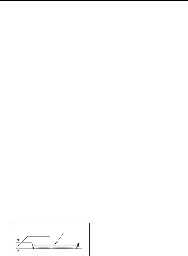
Amount of paper curl:
Max. 10 mm
[6] Maintenance and Life
Maintenance:
Same as the main body
[7] Operating Environment
Temperature:
10 to 30 °C (50 to 86 °F)
Humidity:
10 to 80%RH
Note: The information herein may subject to change for improvement without notice.
Copied paper (5 sheets) |
Amount of curl |
1 - 2
PZ-108/PZ-109
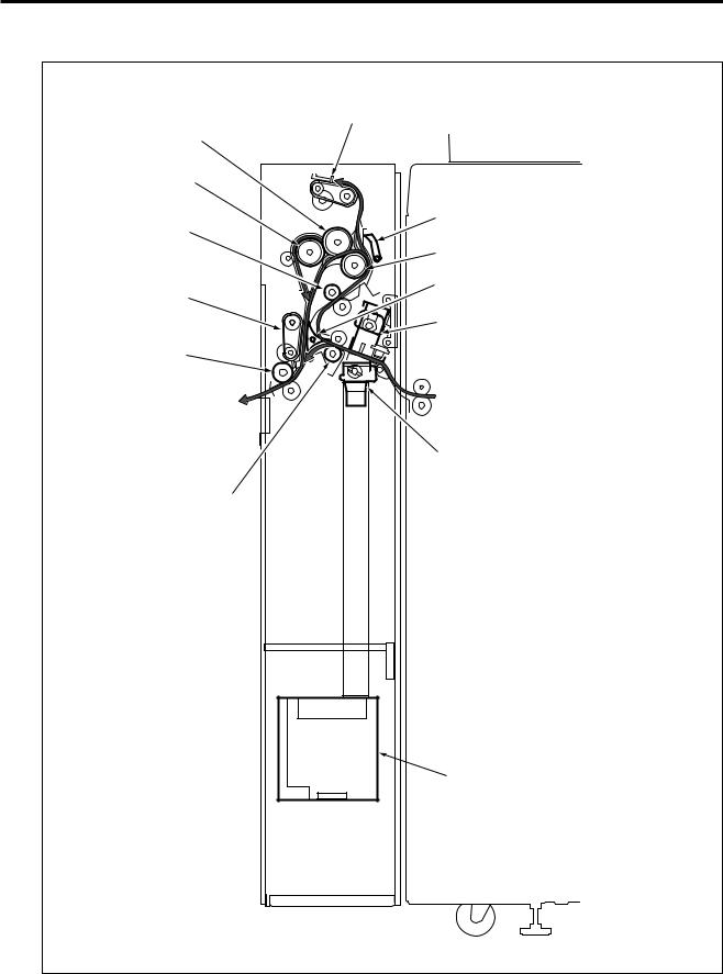
CENTER CROSS-SECTIONAL VIEW
1st folding stopper section
1st folding roller
2nd folding roller
Conveyance roller |
Gate/U switching section |
|
|
|
Conveyance drive roller |
2nd folding stopper |
Gate/L switching section |
|
|
section |
Punch section |
|
|
Exit conveyance roller |
|
(Main body)
Punch scraps conveyance section
Registration section
 Punch scraps box
1 - 3

PZ-108/PZ-109
DRIVE SYSTEM DIAGRAM
[1] Conveyance Drive Section
Conveyance motor (M6) |
2nd folding roller |
1st folding roller |
Gate/U (paper path |
switching for z-folding) |
Conveyance drive roller |
Conveyance roller |
Exit conveyance roller |
Registration roller |
(Main body) |
Registration motor (M1) |
Gate/L (paper path switching) |
FRONT VIEW |
1 - 4

PZ-108/PZ-109
[2] Punch Section
PZ-108 |
Punch motor (M4) |
|
|
|
|
|
|
Punch clutch |
|
|
(MC1) |
|
REAR VIEW |
|
Eccentric cam |
Eccentric cam |
Punch motor (M4) |
|
||
|
Rack |
|
FRONT |
Punch clutch (MC1) |
|
Punch edges |
Timing belt |
|
RIGHT SIDE VIEW |
|
Punch shift motor (M5) |
|
|
PZ-109 |
|
|
|
|
Eccentric cam cover |
|
|
|
|
|
|
|
Punch motor (M4) |
|
Punch switching motor (M8) |
|
|
Punch clutch |
|
|
|
(MC1) |
||
Punch switching cam |
|
|
|
|
TOP VIEW |
|
REAR VIEW |
|
|
|
|
|
||
|
Eccentric cam (Inch area: 5 pcs. / |
Punch motor (M4) |
||
Eccentric cam cover |
Metric area: 4 pcs.) |
|
||
|
|
|
||
Punch switching |
|
|
|
|
motor (M8) |
Punch edges |
|
Rack |
|
FRONT |
(Inch area: 5 pcs. / |
Punch clutch (MC1) |
|
|
|
Metric area: 4 pcs.) |
|
||
RIGHT SIDE VIEW |
|
|
||
|
|
Timing belt |
Punch shift motor (M5) |
|
|
|
1 - 5 |
|
|
PZ-108/PZ-109
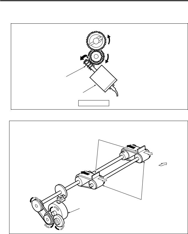
[3] Punch Scraps Conveyance Section
Punch scrap conveyance gear (punch scraps conveyance screw) 
Idler gear 
Worm gear
Punch scraps conveyance motor (M7)
FRONT VIEW
[4] 1st Folding Stopper Section
Paper stopper
FRONT
1st folding stopper
1st stopper motor (M2)
1 - 6
PZ-108/PZ-109
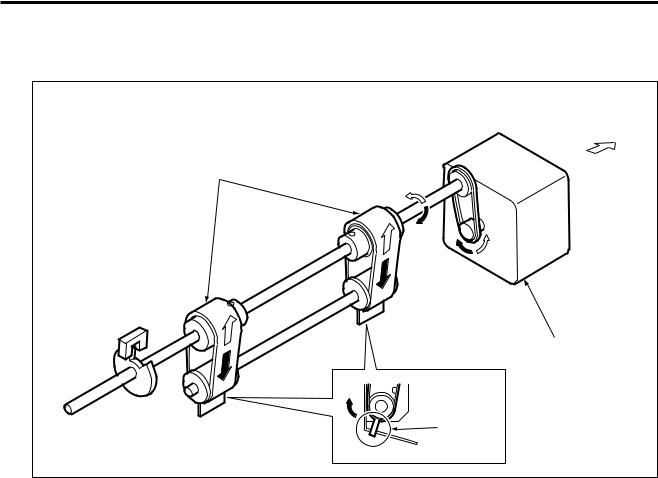
[5] 2nd Folding Stopper Section
FRONT |
2nd folding stopper |
2nd stopper motor (M3) |
Paper |
stopper |
1 - 7
Loading...