


5 ISW
3 DIS./ASSEMBLY5 ISW

5 ISW

ISW
WHAT'S ISW?
ISW (In-System Writer) is a process of updating the control programs stored in flash ROM mounted on various control boards in a Minolta digital copier without isolating the boards from the copier. Running ISW enables you to upgrade control programs without replacing the boards and maintain the boards during their replacement.
Tool available for running ISW include ISW Trns (PC software), which connects a personal computer (PC) to the digital copier.
This tool can be plugged into the ISW connector of the digital copier to directly update the control programs in flash ROM assembled in the machine.
This chapter focuses on instructions to set up this machine to run ISW.
Note: Only ISW Trans is enabled with ISW for this machine.
3 DIS./ASSEMBLY5 ISW
5-1
3 DIS./ASSEMBLY5 ISW
ISW
SETUP
[1] ISW-compatible boards
This machine allows ROM data residing on the following boards to be updated via ISW Tool:
•Image control board
•Printer control board
•Operation board
•RADF control board
•Video I/F board
The ROMs of other boards than the above need to be replaced.
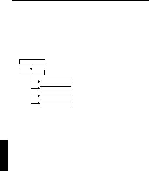
[2] Data flow
PC/ISW Tool
Image control
(2)HELP + CHECK mode
Turning ON the copier with HELP and CHECK puts it into the HELP + CHECK mode. If the copier has the image control program installed, but not the operation control program, the 25 mode would not launch. This mode is specifically maintained to enable ISW in this situation.
2.25 mode
The 25 mode works only where the copier has both the image control and operation control programs installed.
(Some part of HELP+CHECK mode is used to update the operation control program in 25 mode.)
Operation board
Printer control
RADF control board
Video I/F board
Important Note:
The availability of the Graphics control board is prerequisite to updating ROM data on other boards.
[3]Prepare the copier to start an ISW transfer
1.Transfer modes
The copier supports three transfer modes as described below.
(1)Power-on mode
If the copier does not have the image control program installed, its writing to the copier is enabled when the main switch is turned on. Because the image control board controls the power supply to the operation board, nothing will appear on the operation LCD and timer LED will blink even though the operation control program has been installed on the copier.
5-2

|
|
|
|
|
|
ISW |
3. Instances of ISW transfer |
|
|
||||
(1) Writing ROM data newly (Ex. after replacing boards) |
|
|||||
|
|
|
|
|
|
|
|
|
|
|
Normal startup display |
Writing method |
Condition |
|
|
|
|
|
|
|
|
|
Image |
Flashing timer LED |
Writing is enabled with power |
The copier does not have the |
|
|
|
control |
No display on the opera- |
turned ON. |
image control program |
|
|
|
|
|
tion LCD |
|
installed. |
|
|
|
|
|
|
|
|
|
Operation |
Error code display |
Writing is enabled by launch- |
The copier has the image con- |
|
|
|
control |
|
ing the HELP + CHECK mode |
trol program installed. |
|
|
|
|
|
|
|
|
|
|
Others |
Error code display |
25 mode or |
The copier has the image con- |
|
|
|
|
|
|
HELP + CHECK mode |
trol program installed. |
|
|
|
|
|
|
|
(2) Upgrading |
|
|
|
|||
|
|
|
|
|
|
|
|
|
|
|
Normal startup display |
Writing method |
Condition |
|
|
|
|
|
|
|
|
|
Image |
|
Normal |
25 mode or |
The copier has all the programs |
|
|
control |
|
|
HELP + CHECK mode |
installed. |
|
|
|
|
|
|
|
|
|
Operation |
|
Normal |
|
|
|
|
control |
|
|
|
|
|
|
|
|
|
|
|
|
|
Others |
|
Normal |
|
|
|
|
|
|
|
|
|
3 DIS./ASSEMBLY5 ISW
5-3

3 DIS./ASSEMBLY5 ISW
ISW
[4] HELP + CHECK mode operation flow
Power ON (HELP + CHECK) |
|
From the 25 mode menu |
|
|
|
Some parts of this mode is used to update the operation control program from 25 mode.
PC
ISW : Choose a board.
Choose “PC.”
Chose one from followings.
1.GRAPHIC CONTROL (Image control)
2.PRINTER CONTROL (Printer control)
3.OPERATION CONTROL (Operation control)
4.ADF (RADF control)
5.VIF (Video I/F)
ISW : Choose an item. |
Choose from among I1, C1 to C4 (batch or individual), O1 to O5 |
|||||
(batch or individual), F1, and V1. |
||||||
|
|
|||||
PC |
|
|
|
|
|
|
|
|
|
|
|
||
Start ISW : Confirmation window |
|
|
|
|||
|
|
|
|
|
|
|
|
|
|
|
|
|
|
Start ISW |
|
Data |
||||
|
|
|
||||
|
|
|
|
Main Body |
|
|
|
|
|
|
|
|
|
Finish ISW
Exit window
 Normal end : *** NORMAL END ***
 Abnormal end : *** ABNORMAL END ***
DATA ERROR
Changes by the error situation
5-4

ISW
[5]HELP + CHECK mode operating procedure
1.Prerequisite
Turn the main SW ON while pressing “HELP” and “CHECK” button.
2.ISW write mode select menu
Function: This window lets you select a mode in
which to update ISW.
ISW WRITE MODE SELECT MENU
1. PC
PLEASE PUSH TEN-KEY |
9. EXIT |
a.Operating instructions
(1)Choose ISW WRITE MODE
Choose “PC” for both using personal computer and ISW Tool.
(2)To exit writing
Press 9 (EXIT) to open the power-off window.
3.ISW device select menu
Function: This window lets you select the control
board on which to update ROM data. You can choose from among graphics control, printer control, operation control, ADF, and VIF.
ISW WRITE MODE SELECT MENU |
[MODE:PC] |
|
1. |
GRAPHIC CONTROL |
|
2. |
PRINTER CONTROL |
|
3. |
OPERATION CONTROL |
|
4. |
ADF |
|
5. |
VIF |
|
PLEASE PUSH TEN-KEY |
0. PREVIOUS 9. EXIT |
|
|
|
|
a.Operating instructions
(1)Select the control board on which to update ROM data. Choose from among 1 to 5. When you select a number, the associated item select menu appears.
(2)To return to the previous window
Press 0 (PREVIOUS) to return to the ISW write mode select menu.
(3)To exit writing
Press 9 (EXIT) to open the power-off window.
3 DIS./ASSEMBLY5 ISW
5-5

3 DIS./ASSEMBLY5 ISW
ISW
4. Item select menu |
|
|
5. Start confirmation window |
|
||
Function: This window lets you select write |
|
Function: This window prompts you to confirm |
||||
|
items. |
|
|
whether to start running ISW or not. |
||
|
|
|
|
|
||
OPERATION CONTROL - ITEM SELECT MENU [MODE:PC] |
|
OPERATION CONTROL - 01 |
|
[MODE:PC] |
||
1. |
01 |
|
|
|
|
|
2. |
02 |
|
|
|
|
|
3. |
03 |
|
|
ISW START OK? |
|
|
4. |
04 |
|
|
|
|
|
5. |
05 |
|
|
|
|
|
6. |
ALL |
|
|
|
|
|
PLEASE PUSH TEN-KEY |
0. PREVIOUS 9. EXIT |
|
PLEASE PUSH TEN-KEY |
1. YES |
2. NO |
|
|
|
|
|
|
|
|
a.Operating instructions
(1)Individual write
Choose from among 1 to 5. When you select a number, the start confirmation window opens.
(2)Batch write
To write all items in a batch, select “ALL.” When you select “ALL,” the start confirmation window opens.
(3)To return to the previous window
Press 0 (PREVIOUS) to return to the ISW device select menu.
(4)To exit writing
Press 9 (EXIT) to open the power-off window.
a.Operating instructions
(1)Choose YES to start running ISW.
(2)Choose NO to cancel.
When you cancel, the item select menu appears again.
6.Executing window
Function: This window displays the status of
execution in progress.
EXECUTING
a.Operating instructions
(1)The executing indicator flashes. When the execution ends, the ending result window opens.
5-6

ISW
7. Ending result window |
8. Power-off window |
Function: This window displays the status of ISW
ending. |
|
|
|
|
|
|
|
|
|
*** PLEASE TURN OFF A POWER SUPPLY *** |
|
|
|
|
|
|
|
|
|
|
|
|
|
*** NORMAL END *** |
|
|
|
|
|
PLEASE PUSH TEN-KEY |
0. PREVIOUS |
9. EXIT |
|
|
|
|
a. |
Operating instructions |
|||
|
|
|
|
||
Abnormal end |
|
|
|||
|
(1) |
Individual write |
|||
|
|
|
|
|
Choose from among 1 to 5. When you select a |
|
|
|
|
|
|
|
|
|
|
|
number, the start confirmation window opens. |
*** ABNORMAL END *** |
|
|
|
|
|
INPUT DEVICE ERROR |
|
|
|
|
|
(ERROR CODE : xx) |
|
|
|
|
|
PLEASE PUSH TEN-KEY |
0. PREVIOUS |
9. EXIT |
|
|
|
|
|
|
|
|
|
a.Operating instructions
(1)Choose 0 (CONTINUE) to return to the item select menu.
(2)To exit writing
Press 9 (EXIT) to open the power-off window.
3 DIS./ASSEMBLY5 ISW
5-7
 Loading...