


FLASH METER VI
Instruction Manual
Manuel d’instructions
The essentials of imaging L’essentiel de l’image
E
F
Instruction Manual
FLASH METER VI
Thank you for purchasing the MINOLTA FLASH METER VI.
The Minolta Flash Meter VI has the following features:
●The integrated exposure meter combines incident light measurement and spot (reflected light) measurement in a single unit.
●For spot measurement, the Flash Meter VI uses a parallax-free optical system. This eliminates the displacement of the measurement area that varies with the distance from the subject.
●With the latitude display function, the Flash Meter VI can simultaneously display the results of both incident light measurement and spot light measurement. It provides a clear and simple graphical decision process for determining the exposure suited to the nature of the photograph.
●With the analyze scale, you can determine the proportion of flash light and ambient light in a single flash light measurement.
●The Flash Meter VI provides a memory function capable of storing up to 10 measured values; an averaging function that calculates an average exposure from stored measurement data; and a brightness difference function that displays deviation from the standard exposure.
●For spot measurement, both shadow-based and highlight-based exposure calculation functions are provided.
●The Flash Meter VI provides a "custom setting (Alt) mode" that allows you to customize the meter according to your preference. This feature includes an exposure correction value setting function and a shutter speed increment-setting function.
●Measurement results are shown on both the analog and digital displays on the meter’s data panel. The clear and legible display eliminates reading errors.
●The results of spot measurements are shown on the digital display in the viewfinder and on the external data panel. The viewfinder features a dioptric adjustment mechanism.
●In addition to displaying a conventional 10-level intermediate f-number display, the Flash Meter VI provides an f-number direct reading display. This enables the measured value to be applied to any camera with an f- number direct reading display, eliminating the need for f-number conversion.
Safety-related Icons
The following icons are used in this manual to alert you to important information for preventing accidents due to improper handling of equipment.
This denotes a safety-related caution. Read the caution carefully to ensure safe use of the product.
This denotes actions to be strictly avoided.
Make sure to avoid these actions.
This denotes actions to be avoided.
Do not attempt to disassemble the product.
Safety Warnings and Cautions
To ensure proper use of the instrument, take special care to observe the following handling instructions when using this instrument. Read this instruction manual carefully and keep it securely in a place where you can refer to it readily.
indicates a danger that improper use of the WARNING instrument will lead to the death or serious
injury of the user.
Do not use the instrument in a place where inflammable or combustible vapors (e.g. gasoline) are present. Otherwise there is a risk of causing a fire.
Do not throw batteries into fire. Do not recharge (nonrechargeable batteries), short circuit, heat or disassemble batteries. Otherwise, there is a risk of causing fire or injury due to an explosion or fluid leakage.
Never attempt to disassemble or modify the instrument yourself. Otherwise there is a risk of causing fire or electric shock.

Never attempt to look directly at the sun through the viewfinder of the meter. Doing so will damage your eyesight.
The instrument should not be operated if it is damaged, or smoke or odd smells occur. Doing so may result in a fire. In such situations turn off the power immediately, disconnect the AC adapter, and contact the nearest authorized service facility.
indicates a danger that improper use of the CAUTION instrument will lead to injury to the user or to
property damage.
Do not use any batteries other than those designated for use with the instrument. When fitting batteries, make sure to align them according to the polarity shown on the instrument (plus "+" and minus "-"). Otherwise there is a risk that the batteries may leak or become damaged, leading to fire, injury or pollution of the surrounding environment.
Do not walk around while looking into the viewfinder. Doing so may result in a fall or other accident.
STATEMENT OF FCC COMPLIANCE
This equipment has been tested and found to comply with the limits for a Class B digital device, pursuant to Part 15 of the FCC Rules. These limits are designed to provide reasonable protection against harmful interference in a residential installation. This equipment generates, uses and can radiate radio frequency energy and, if not installed and used in accordance with the instructions, may cause harmful interference to radio communications. However, there is no guarantee that interference will not occur in a particular installation. If this equipment does cause harmful interference to radio or television reception, which can be determined by turning the equipment off and on, the user is encouraged to try to correct the interference by one or more of the following measures:
-Reorient or relocate the receiving antenna.
-Increase the separation between the equipment and receiver.
-Connect the equipment into an outlet on a circuit different from that to which the receiver is connected.
-Consult the dealer or an experienced radio/TV technician for help.
This Class B digital apparatus complies with Canadian ICES-003.
Table of Contents
Names of Parts and Displays 2
●Data panel displays 4
●Viewfinder display 8
Preparations 9
●Battery 9
1.Preparing 9
2.Inserting 9
3.Checking 10
●Setting film speed 12
● Setting instant film speed for test shooting 13 ● Selecting a measuring method suitable for the light-receiving method 14
1.Incident light measurement 14
2.Spot measurement 15
*Difference between incident-light and Spot (reflected-light) readings 16
Basic Operation 19
●Select a measuring method 19
●Measuring ambient light 20
1.With a still camera 20
2.With a cine camera 24
●Measuring flash light 27
1.With a sync cord 27
2.Without a sync cord (Incident light measurement) 32 * Light Ratio Analyze function 36
Special Functions 38 ● Latitude display function 38 * Combining incident light measurement and spot measurement 40
●Memory function 42
●S/A/H (Shadow/Average/Highlight) calculations 45
●Brightness difference function 52
* Measuring lighting ratio using the Flat Diffuser 58
* |
Using the Flash Meter VI as a simplified illuminance meter 63 |
* |
Using the Flash Meter VI as a simplified luminance meter 63 |
● Custom settings mode (Alt mode) 66
Accessories 74
Care and Storage 75
1.Care 75
2.Storage 75
Handling Instructions 76 ● After Service 77
Specifications 78
E1

Names of Parts and Displays
Names of Parts and Displays
Incident light receptor |
|
|
Spot measurement |
POWER button |
Dioptric |
adjustment |
||
viewfinder |
|
dial |
Spot measuring |
Incident light |
|
button |
measuring button |
|
|
|
Up/down |
Data panel |
|
dial |
|
|
|
ISO button |
|
|
|
LATITUDE button |
|
|
MODE button |
|
|
MEMORY button |
Battery chamber cover |
|
S/A/H button |
|
|
|
|
|
Sync terminal |
Strap eyelet |
|
|
|
|
CLR (Clear) button |
|
|
Instant film ISO button |
|
E2 |
E3 |

Names of Parts and Displays
Data panel displays
1.Analog scale status indicator
4.Measurement data status indicator
5. S/A/H indicator |
|
6. |
indicator |
Pointers |
|
3.Analog scale R
2.Analog scale L
For the purpose of explanation, the diagram above shows all indicators that light up on the LCD.
Names of Parts and Displays
1.Analog scale status indicator
The left (L) and right (R) analog scales are used for incident light measurement and spot measurement, respectively.
2.Analog scale L
The display of the pointers corresponds to measurement data and memory data for incident light measurement. It also corresponds to the
standard exposure or latitude for incident light measurement or spot measurement.
The small digit to the right of the two-digit reading (f-number) on the digital readout indicates a fractional value between stops. The value shown on the analog display is rounded down or up to the nearest 0.5 stops. (Values of 0.2 or lower are rounded down to 0; those of 0.3 to 0.7 are rounded to 0.5; and those of 0.8 or greater are rounded up to 1.)
When a latitude range is indicated, all dots between the upper and lower limits are lit.
3.Analog scale R
The display of the pointers corresponds to measurement data and memory data for spot measurement.
The small digit to the right of the two-digit reading (f-number) on the digital readout indicates a fractional value between stops. The value shown on the analog display is rounded down or up to the nearest 0.5 stops. (Values of 0.2 or lower are rounded down to 0; those of 0.3 to 0.7 are rounded to 0.5; and those of 0.8 or greater are rounded up to 1.)
4.Measurement data status indicator
When a value measured with incident light measurement is displayed,
the  indicator appears. When a value measured with spot measurement is displayed, the
  indicator appears.
5.S/A/H indicator
Holding down the S/A/H button while a measured value is displayed
lights the S, A or H indicator corresponding to the currently selected


 mode.
mode.
6. indicator
This indicator turns on when the LATITUDE button is pressed.
E4 |
E5 |

Names of Parts and Displays
7. Digital readout |
8. Shutter speed/framing- |
rate display |
9. Analyze scale |
10.Flash light measuring |
indicator |
11.Film speed display |
12.Measuring mode |
display |
For the purpose of explanation, the diagram above shows all indicators that light up on the LCD.
Names of Parts and Displays
7.Digital readout
When the measurement data display unit is set to "FNo." or "FNo. direct reading," the f-number (FNo.) is displayed. When the display unit is set to "EV," the exposure value (EV) is displayed in 0.1-stop increments. For flash light measurement, only the FNo. display mode is available. Holding down the incident light measuring button or spot measuring button (which activates the brightness difference function) in latitude display mode causes ∆EV (deviation from the standard exposure) to be displayed. When the measuring button is released, the standard exposure is displayed.
8.Shutter speed/framing-rate display
Displays the shutter speed or frame rate specified with the Up/down dial. When shutter speed is between 0.6 to 50 sec, s is displayed; between 1
min. and 30 min., m is displayed.
Setting range: Shutter speed: 30 min. to 1/16000 sec. (1, 1/2, 1/3 stops)
Framing-rate: 8, 12, 16, 18, 24, 25, 30, 32, 64,128 f/s
9.Analyze scale
Displays the proportion of flash light in the total exposure value obtained from flash light measurement. For more information on the Light Ratio Analyze function, see p. 36.
10.Flash light measuring indicator
This indicator appears together with the analyze scale in CORD and NON CORD mode.
11.Film speed display
Displays the film speed setting.
Holding down the  instant film ISO button displays the
  indicator. Setting range: ISO 3 to ISO 8000
12.Measuring mode display
Displays one of the three measurement modes (AMBI, CORD or NON CORD) according to the setting of the MODE button.
Repeatedly pressing the MODE button cycles the measurement modes in the following sequence:
AMBI CORD NON CORD AMBI
E6 |
E7 |

Names of Parts and Displays
Viewfinder display
15.Measuring index circle
14.Viewfinder FNo./EV display
13.Viewfinder  indicator
For the purpose of explanation, the above figure shows all available indicators on the display.
13.Viewfinder  indicator
Same as the  indicator on the external data panel.
14.Viewfinder FNo./EV display
Displays an f-number (FNo.) or exposure value (EV) during spot measurement.
15.Measuring index circle
The circle’s internal area indicates the measuring area for spot measurement.
Preparations
Battery
 WARNING
Do not throw batteries into fire. Do not recharge (nonrechargeable batteries), short circuit, heat or disassemble batteries. Otherwise, there is a risk of causing fire or injury due to an explosion or fluid leakage.
 CAUTION
Do not use any batteries other than those designated for use with the instrument. When fitting batteries, make sure to align them according to the polarity shown on the instrument (plus "+" and minus "-"). Otherwise there is a risk that the batteries may leak or become damaged, leading to fire, injury or pollution of the surrounding environment.
1. Preparing
The instrument uses a single alkaline dry cell (LR-6/1.5 V).
2. Inserting
1 Remove the battery chamber cover by sliding it lightly in the direction of the arrow.
2 Insert the battery with the plus (+) and minus (-) ends oriented according to the diagram in the battery chamber.
The meter will not work if the battery is inserted in the
wrong direction. |
E9 |
E8

Preparations |
Preparations |
3 Replace the battery chamber cover.
3. Checking
The instrument automatically checks the battery when power is on.
After a new battery is installed, the display appears as shown below after the power is turned on.
If you turn on the meter when the battery power is running low, "b.c." will appear on the display for approx. 0.5 sec. before the normal display appears.
If you turn the power on when there is not enough battery power to take measurements, or if the battery runs low during measurement, a blinking "b.o." will display for approx. 1 min. and then the display will switch off. If this happens, replace the battery with a new one.
When disposing of used batteries, observe local waste disposal regulations.
●The Flash Meter VI can be operated continuously for about 30 hours with a fresh alkaline dry cell.
●The Flash Meter VI has a power-saving function that automatically turns off the power after about 10 minutes of inactivity.
To restart measuring operation after the display has been turned off, press the POWER button. (Pressing the POWER button restores the meter to the condition it was in before the power was turned off. The settings for film speed, shutter speed, measuring mode and display unit, as well as the existing measurement data and memory data, are all retained in memory.)
E10 |
E11 |
Preparations
Setting film speed
Specify a film speed with the Up/down dial while holding down the ISO button.
● Turning the control upward increases the film speed in increments of 1/3-stop. The maximum film speed is ISO 8000.
● Turning the control downward lowers the film speed in decrements of 1/3-stop. The
minimum film speed is ISO 3.
● Be sure to set film speed to the
correct setting, since all
measurement results are based on the set value.
● If you change the film speed after you take a measurement, the reading will be recalculated and displayed accordingly.
Preparations
Setting instant film speed for test shooting
If the film speed setting used for the final shooting is different from the instant film speed setting used for test shooting, the instant film speed can be registered in the meter in advance. Once an instant film speed is registered for test shooting, the meter converts the measurement result into a value based on this setting when the  instant film ISO button is pressed after measurement.
Specify an instant film speed with the up/down dial while holding down the
 instant film ISO button.
● Turning the control upward increases the film speed in increments of 1/3-stop. The maximum film speed is ISO 8000.
● Turning the control downward lowers the film speed in decrements of 1/3-stop. The
minimum film speed is ISO 3. ● If you change the instant film
speed after you take a measurement, the reading will be recalculated and displayed accordingly.
E12 |
E13 |

Preparations
Selecting a measuring method suitable for the light-receiving method
Select a measuring method, either incident light measurement or spot measurement, appropriate to the shooting conditions and nature of the photograph. The Flash Meter VI can measure exposure in either way. For incident light measurement, select either the Spherical Diffuser or optional Flat Diffuser.
1. Incident light measurement
When performing incident light measurements, use the Spherical Diffuser for three-dimensional subjects such as portraits, and architectural or landscape photographs. Use the Flat Diffuser when you photograph flat surfaces such as documents or paintings, or when you want to measure lighting ratio (See page 58.).
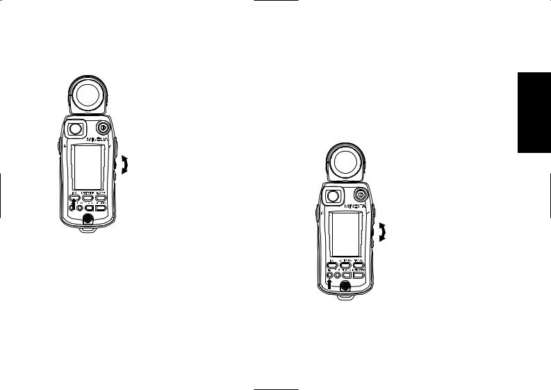
Attaching the Spherical Diffuser
Align the index mark (white circle) of the Spherical Diffuser with the index of the receptor head. Secure the diffuser by turning it in the direction indicated by the arrow until it stops.
Removing the Spherical Diffuser
Rotate the diffuser anticlockwise until it stops, and pull the diffuser to detach it.
To take an incident light measurement, position the meter near the subject and aim the Spherical Diffuser directly at the camera.
●The receptor can rotate through a range of 270 degrees, so that you can use the meter in an almost any photographic configuration.
|
Preparations |
WARNING |
Never attempt to look directly at the sun through |
|
the viewfinder of the meter. Doing so will |
|
damage your eyesight. |
CAUTION |
Do not walk around while looking into the |
|
viewfinder. Doing so may result in a fall or other |
|
accident. |
2. Spot measurement
To measure a specific area of a photographic image, select the spot measurement method (with a light-receiving angle of 1 degree).
To take a spot measurement,
• position the meter near the camera,
•look into the viewfinder at the front of the meter (data panel side),
•locate the measuring index (circle) at the center of the viewfinder within the desired measuring point of the subject, and
•press the spot measuring button.
The allowable measuring distance from the subject is 1.3 m to infinity (∞).
To stabilize your shooting posture and avoid shaking the meter, turn the receptor head toward the subject and hold the meter by placing your hand over it as shown above.
Dioptric adjustment
While looking into the viewfinder for a spot measurement, adjust the dioptric by turning the dioptric adjustment dial until the measuring index circle can be clearly seen.
E14 |
E15 |
Preparations
Difference between incident-light and Spot (reflected-light) readings
Exposure can be measured in two basic ways. One way is to measure the light incident on the subject, i.e. the brightness of light illuminating the subject (illuminance) (see Fig. 1); the other is to measure the light Spot reflected by the subject, i.e. the intensity of the light reflected from the subject in the direction of the camera (luminance) (see Fig. 2).
Fig. 1 Incident-light method |
Fig. 2 Spot (Reflected-light) method |
Light source
Incidentlight
Camera
Light source
Reflected-  Camera
light
Before selecting the most suitable measuring method, you need to fully understand the different sources of light you are working with, as well as the influence of the positions and direction of receptors during measurement.
Incident-light readings
In general photography, light from the illuminating light source reflects off the subject and passes through the lens to form an image on the film, and to expose the film.
To accurately calculate exposure in incident-light readings, you need to know how much of the illuminating light is actually reflected from the object to the camera. To do this, you need to know how light or how dark the subject is, i.e. the reflectance of the subject.
Since a typical value of reflectance for many scenes is 18%*, this value is used to calculate the light intensity reflected from the subject towards the camera. The exposure reading (f-number and shutter speed) are then calculated to reproduce the metered area as a midtone with 18% reflectance.
Preparations
Thus, incident-light readings are based on this standard value of 18% reflectance. This means that areas of subjects having a reflectance higher than 18% will turn out brighter (e.g. white), while areas of reflectance lower than 18% will turn out darker (e.g. black). This will produce a clear contrast in the picture of the subject. From this, we can see that this measuring method provides for natural tonal range over the entire composition.
*The value of “18%” has been determined to be a typical reflectance value for many different subjects.
Fig. 3
(a)(b)
Threedimensional subjects
Flat subjects
To make effective incident-light exposure readings, you must use the Spherical Diffuser and Flat Diffuser creatively.
When photographing three-dimensional objects such as people, the highlights and shadow areas of a composition depend on the direction of the main illuminating light source. Exposure is also influenced by any light reflected towards the camera from the sides or rear of the subject (Fig. 3 (a)). In these situations, the Spherical Diffuser captures the illuminating light coming from different directions at the position of the subject, so that the exposure reading takes into account the contribution of this light on illuminating the subject. On the other hand, with flat subjects such as pictures and documents, light from the sides or rear of the subject generally make little or no contribution to illuminating the subject (Fig. 3(b)). So, for these situations, accurate exposure readings are made using a Flat Diffuser to capture only the illuminating light from the front of the subject.
E16 |
E17 |
Preparations
Spot (reflected-light) readings
Spot (reflected-light) exposure readings directly measure the amount of light (luminance) reflected from the subject to the camera. Unlike the case of incident-light readings, this method does not rely on the assumption of a standard subject reflectance of 18%. Based on the measured amount of light falling on the subject, the meter calculates the appropriate exposure value for reproducing the subject on film at a suitable medium density (midtone). This means that in Spot (reflected-light) readings, all subjects, regardless of their reflectance, i.e. regardless of whether they are bright or dark (white or black), will be reproduced at the same tonal density (midtone). For this reason, when making Spot (reflected-light) exposure readings, it is important to decide which area of the subject to measure, since the reflectance will generally vary quite widely over the composition under different conditions.
There are various advanced Spot (reflected-light) readings, such as the highlight standard exposure method, where an exposure reading is taken of a bright (white) part of the composition; the shadow standard exposure method, where a dark (black) part of the composition is measured; and a method for determining exposure by evaluating the contrast of the subject and then forecasting how it will come out on film. To make full use of Spot (reflected-light) readings, refer to specialist books and photo magazines. You will find that selective metering can give you very precise control over exposure.
E18
Basic Operation
Here we explain the basics of using the MINOLTA FLASH METER VI to take exposure readings.
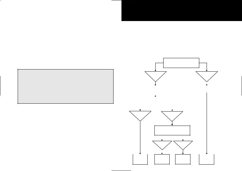
Select a measuring method
●Flash light refers to artificial momentary lighting from light sources such as electronic flashes, strobe flashes, and speed lights.
●Ambient light refers to continuous lighting from sources such as natural light (sunlight) and electric lights (including fluorescent lights).
●In either case, both incident-light exposure readings and spot-light exposure readings can be made.
Are you using a still camera?
Are you using a cine camera?
|
|
|
|
With a still |
|
|
|
|
|
|
With a cine |
|
|||||
|
|
|
|
camera |
|
|
|
|
|
|
camera |
|
|||||
|
Alt mode |
|
|
|
|
|
|
|
|
|
|
|
|
|
|||
|
|
|
|
|
|
|
|
|
Alt mode |
|
|
|
|
||||
|
|
|
|
|
|
|
|
|
|
|
|
|
|||||
|
|
Select TIME (P.72) |
|
|
|
|
|
Select CINE (P.72) |
|
|
|||||||
|
|
|
|
|
|
|
|
|
|
|
|
|
|
|
|
|
|
|
|
|
|
|
|
|
|
|
|
|
|
|
|
|
|
|
|
|
|
|
|
|
|
|
|
|
|
|
|
|
|
|
|
|
|
|
|
Type of light source to |
|
|
|
|
|
|
|
|
|
|
|
||||
|
|
|
|
measure |
|
|
|
|
|
|
|
|
|
|
|
||
|
|
|
|
|
|
|
|
|
|
|
|
|
|
|
|||
|
|
|
|
|
|
|
|
|
|
|
|
|
|
|
|
||
Ambient light |
|
|
Flash light |
|
|
|
|
|
|
||||||||
|
|
|
|
|
|
|
(mixed |
|
|
|
|
|
|
||||
|
|
|
|
|
|
|
light) |
|
|
|
|
|
|
||||
|
|
|
|
|
Are you using a sync cord? |
|
|
|
|
|
|
||||||
|
|
|
|
|
|
|
|
|
|
|
|
|
|
|
|
|
|
|
|
|
|
|
|
|
|
|
|
|
|
|
|
|
|
|
|
|
|
|
|
|
With a sync |
|
|
Without a |
|
|
|
|
|
|
|||
|
|
|
|
|
cord |
|
|
sync |
|
|
|
|
|
|
|||
|
|
|
|
|
|
|
cord |
|
|
|
|
|
|
||||
|
|
|
|
|
|
|
|
|
|
|
|
|
|
|
|||
|
|
|
|
|
|
|
|
|
|
|
|
|
|
|
|
|
|
|
|
|
|
|
|
|
|
|
|
|
|
|
|
|
|
|
|
|
|
|
|
CORD |
|
|
|
|
|
|
|
|
|
|
|||
AMBI |
|
|
|
NON CORD |
|
AMBI |
|
||||||||||
mode |
|
mode |
|
|
mode |
|
mode |
|
|||||||||
(p. 20) |
|
(p. 27) |
|
|
(p. 32) |
|
(p. 24) |
|
|||||||||
E19
Basic Operation
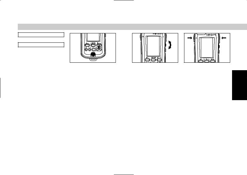
Measuring ambient light
1. With a still camera
Insert a battery (p. 9)
↓
Set film speed (p. 12)
1 Prepare the meter to start |
2 Press the MODE button to |
taking readings. |
switch the mode display to |
|
AMBI. |
|
● Changing the measuring mode |
|
retains the memory data but |
|
clears previous measurement |
|
data. |
E20
Basic Operation
3 Specify the desired shutter speed with the up/down dial.
●Shutter speed can be set within the range of 30 min. to 1/16000 sec.
●Turning the up/down dial upward increases the shutter speed. Turning it downward lowers the shutter speed.
●The shutter speed can also be changed after meter readings.
Spot measuring |
button |
Incident light |
measuring button |
4 Press the measuring button to take readings.
●The meter takes measurements continuously as you hold down the incident light measuring button. The digital display on the data panel displays the measurement data. At the same time, the measurement data are also displayed on the dot indicator of the analog scale L. When the measuring button is released, the meter stops taking measurements and displays only the latest measurement result.
●The meter takes measurements continuously as you hold down the spot measuring button. The digital display in the viewfinder displays the measurement data. At the same time, the measurement data are also displayed on the dot indicator of the analog scale R. When the measuring button is released, the meter stops taking measurements. The latest measurement result appears on the digital display of the external data panel and on the dot indicator of the analog scale R display.
●Pressing the CLR button
clears the measurement data. E21
 Loading...