


EP1085

FrameMaker Ver.5.5E(PC) COVER [FIELD SERVICE] FOR EP1054/EP1085/EP2030
98.09.11
FrameMaker Ver.5.5E(PC) COVER [FIELD SERVICE] FOR EP1054/EP1085/EP2030
98.09.11
Copyright
1998 MINOLTA CO., Ltd.
Printed in Japan
Use of this manual should
be strictly supervised to
avoid disclosure of
confidential information.
MINOLTA CO., LTD.
1174-7991-11 98114400
EP1054/EP1085/EP2030
SERVICE MANUAL
EP1054/EP1085/EP2030 SERVICE MANUAL
[
FIELD SERVICE
]
[
FIELD SERVICE
]
FrameMaker Ver.5.5E(PC) PL Standard Document Ver.01
98.10.02
P-1
Safety Precautions for Inspection and Service
When performing inspection and service procedures, observe the following precautions to
prevent accidents and ensure utmost safety.
✽
Depending on the model, some of the precautions given in the following do not apply.
Different markings are used to denote specific meanings as detailed below.
Indicates a potentially hazardous situation which, if not avoided,
could result in death or serious injury.
Indicates a potentially hazardous situation which, if not avoided,
may result in minor or moderate injury. It may also be used to
alert against unsafe practices.
The following graphic symbols are used to give instructions that need to be observed.
Used to call the service engineer attention to what is graphically represented
inside the marking (including a warning).
Used to prohibit the service engineer from doing what is graphically represented
inside the marking.
Used to instruct the service engineer to do what is graphically represented inside
the marking.
1. Always observe precautions.
2. Before starting the procedures, be sure to unplug the power cord.
3. Use the specified parts.
WARNING
CAUTION
WARNING
•
Parts requiring special attention in this product will include a label containing the
mark shown on the left plus precautionary notes. Be sure to observe the pre-
cautions.
•
Be sure to observe the “Safety Information” given in Operator’s Manual.
•
This product contains a high-voltage unit and a circuit with a large current
capacity that may cause an electric shock or burn.
•
The product also contains parts that can jerk suddenly and cause injure.
•
If this product uses a laser, laser beam leakage may cause eye damage or
blindness.
•
For replacement parts, always use the genuine parts specified in the manufac-
turer’s Parts Manual. Installing a wrong or unauthorized part could cause
dielectric breakdown, overload, or undermine safety devices resulting in possi-
ble electric shock or fire.
•
Replace a blown electrical fuse or thermal fuse with its corresponding genuine
part specified in the manufacturer’s P arts Manual. Installing a f use of a different
make or rating could lead to a possible fire. If a thermal fuse blows frequently,
the temperature control system is probably of a problem and action must be
taken to eliminate the cause of the problem.

FrameMaker Ver.5.5E(PC) PL Standard Document Ver.01
98.10.02
P-2
4. Handle the power cord with care and never use a multiple socket.
5. Be careful about the high-voltage parts.
6. Do not keep your hands wet when performing the procedures.
7. Do not touch a high-temperature part.
8. Make a ground connection at all times (This item may not be effected in USA).
9. Do not remodel the product.
10. Restore all parts and harnesses to their original positions.
•
Do not brake, crush or otherwise damage the power cord. Placing a heavy
object on the power cord, or pulling or bending it may damage it, resulting in a
possible fire or electric shock.
•
Do not use a multiple outlet to which any other appliances or machines is con-
nected.
•
Be sure the power outlet meets or exceeds the specified capacity.
•
A part marked with the symbol shown on the left carries a high voltage. Touch-
ing it could result in an electric shock or burn. Be sure to unplug the power cord
before servicing this part or the parts near it.
•
Do not unplug or plug in the power cord, or perform any kind of service or
inspection with wet hands. Doing so could result in an electric shock.
•
A part marked with the symbol shown on the left and other parts such as the
exposure lamp and fusing roller can be very hot while the machine is energized.
Touching them may result in a burn.
•
Wait until these parts have cooled down before replacing them or any surround-
ing parts.
•
Be sure to connect a ground wire to the ground terminal even when performing
an inspection or repair. Without proper grounding, electrical leakage could
result in an electric shock or fire.
•
Never connect the ground wire to a gas pipe, water pipe, telephone ground wire,
or a lightning conductor.
•
Modifying this product in a manner not authorized by the manufacturer may
result in a fire or electric shock. If this product uses a laser, laser beam leakage
may cause eye damage or blindness.
•
To promote safety and prevent product damage, make sure the harnesses are
returned to their original positions and properly secured in their clamps and sad-
dles in order to avoid hot parts, high-voltage parts, and sharp edges, or being
crushed.
•
To promote safety, make sure that all tubing and other insulating materials are
returned to their original positions. Make sure that floating components mounted
on the circuit boards are at their correct distance and position off the boards.
FrameMaker Ver.5.5E(PC) PL Standard Document Ver.01
98.10.02
P-3
1. Precautions for Service Jobs
2. Precautions for Servicing with Covers and Parts Removed
3. Precautions for Working Environment
4. Precautions for Handling Batteries (Lithium, Nickel-Cadmium, etc.)
CAUTION
•
A toothed washer and spring washer, if used originally, must be reinstalled.
Omitting them may result in contact failure which could cause an electric shock
or fire.
•
When reassembling parts, make sure that the correct screws (size, type) are
used in the correct places. Using the wrong screw could lead to stripped
threads, poorly secured parts, poor insulating or grounding, and result in a mal-
function, electric shock or injury.
•
Take great care to avoid personal injury from possible burrs and sharp edges on
the parts, frames and chassis of the product.
•
When moving the product or removing an option, use care not to injure your
back or allow your hands to be caught in mechanisms.
•
Wherever feasible, keep all parts and covers mounted when energizing the
product.
•
If energizing the product with a cover removed is absolutely unavoidable, do not
touch any exposed live parts and use care not to allow your clothing to be
caught in the moving parts. Never leave a product in this condition unattended.
•
Never place disassembled parts or a container of liquid on the product parts fall-
ing into, or the liquid spilling inside, the mechanism could result in an electric
shock or fire.
•
Never use a flammable spray near the product. This could result in a fire.
•
Make sure the power cord is unplugged before removing or installing circuit
boards or plugging in or unplugging connectors.
•
Always use the interlock switch actuating jig to actuate an interlock switch when
a cover is opened or removed. The use of folded paper or some other object
may damage the interlock switch mechanism, possibly resulting in an electric
shock, injury or blindness.
•
The product must be placed on a flat, level surface that is stable and secure.
•
Never place this product or its parts on an unsteady or tilting workbench when
servicing.
•
Provide good ventilation at regular intervals if a service job must be done in a
confined space for a long period time.
•
Avoid dusty locations and places exposed to oil mist or steam.
•
Avoid working positions that may block the ventilation port of the product.
•
Replace a rundown battery with the same type as specified in the manufac-
turer’s parts manual.
•
Before installing a new battery, make sure of the correct polarity of the installa-
tion or the battery could burst.
•
Dispose of used batteries according to the local regulations. Nev er dispose of
them at the user’s premises or attempt to try to discharge one.
FrameMaker Ver.5.5E(PC) PL Standard Document Ver.01
98.10.02
P-4
5. Precautions for Laser Beam (Products Employing Laser Only)
.
•
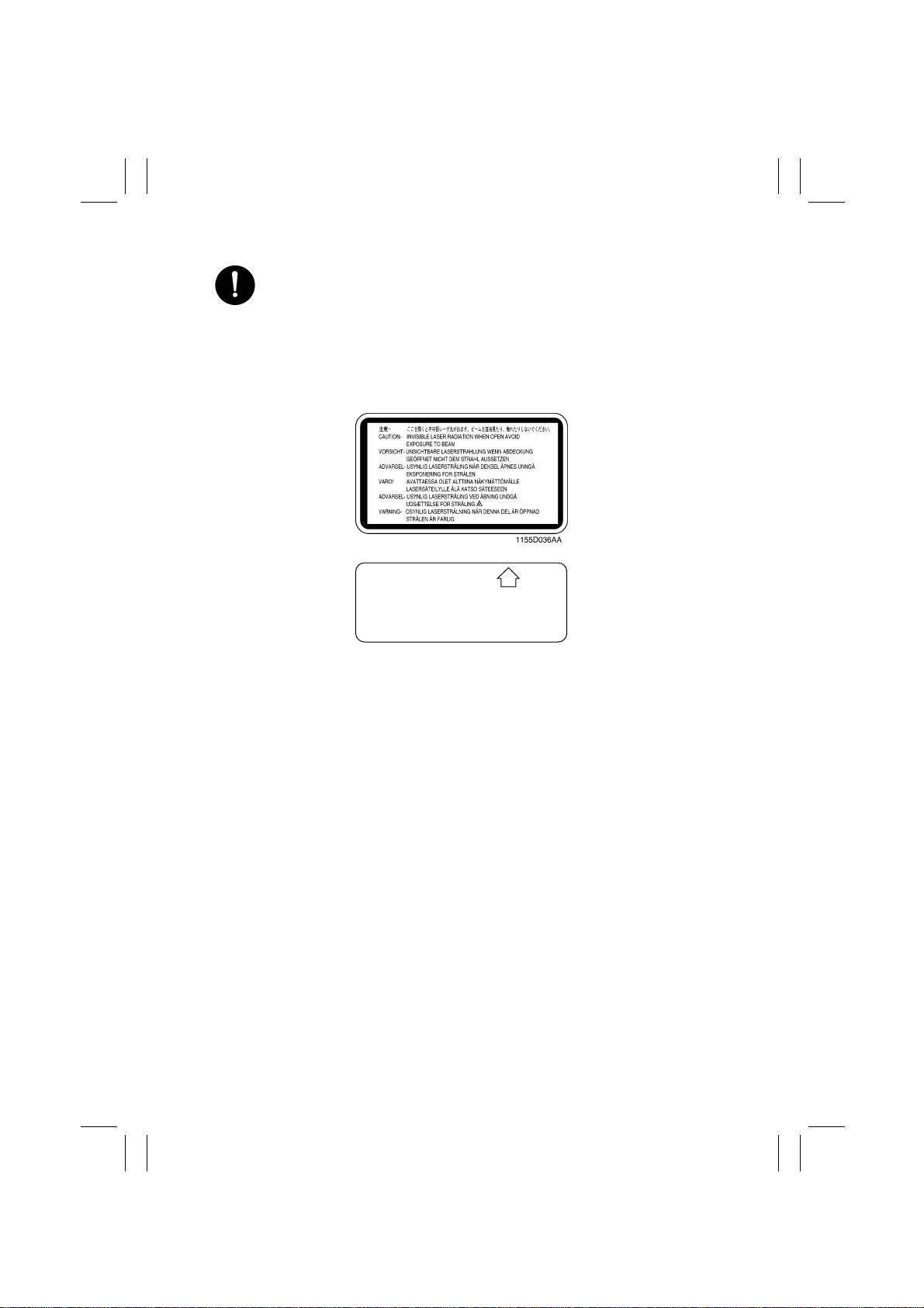
Removing the cover marked with the follo wing caution label could lead to possi-
ble exposure to the laser beam, resulting in eye damage or blindness. Be sure
to unplug the power cord before removing this cover.
•
If removing this cover while the power is ON is una voidable, be sure to wear pro-
tective laser goggles that meet specifications.
•
Make sure that no one enters the room when the machine is in this condition.
•
When handling the laser unit, observe the “Precautions for Handling Laser
Equipment.”
DANGER
Invisible laser radiation when open.
AVOID DIRECT EXPOSURE
TO BEAM
0947-7127-01
1144D270AA

FrameMaker Ver.5.5E(PC) PL Standard Document Ver.01
98.10.02
P-5
•
To reassemble the product, reverse the order of disassembly unless otherwise specified.
•
While the product is energized, do not unplug or plug connectors into the circuit boards
or harnesses.
•
The magnet roller generates a strong magnetic field. Do not bring it near a watch, floppy
disk, magnetic card, or CRT tube.
•
An air gun and vacuum cleaner generates a strong electrostatic charge that can destroy
the ATDC sensor and other sensors. Before cleaning a component with one of these
devices, be sure to remove all the sensors. Otherwise, use a blower brush and cloth
when cleaning parts.
•
When handling circuit boards with MOS ICs, observe the “INSTRUCTIONS FOR HAN-
DLING THE PWBs WITH MOS ICs” (applicable only to the products using MOS ICs).
•
The PC Drum is a very delicate component. Observe the precautions given in “HAN-
DLING OF THE PC DRUM” because mishandling may result in serious image problems.
•
Note that replacement of a circuit board may call for readjustments or resetting of partic-
ular items, or software installation.
•
After completing a service job, perform a safety check. Make sure that all parts, wiring
and screws are returned to their original positions.
•
Check the area surrounding the service site for any signs of damage, wear or need of
repair.
•
Do not pull out the toner hopper while the toner bottle is turning. This could result in a
damaged hopper motor or locking mechanism.
•
If the product is to be run with the front door open, make sure that the toner hopper is in
the locked position.
Other Precautions

FrameMaker Ver.5.5E(PC) PL Standard Document Ver.01
98.10.02
P-6
(ALL Areas)
CAUTION
Danger of explosion if battery is incorrectly replaced.
Replace only with the same or equivalent type recommended by the manufacturer.
Dispose of used batteries according to the manufacturer’s instructions.
(Germany only)
VORSICHT!
Explosinsgefahr bei unsachgemäßen austausch der batterie.
Ersatz nur durch denselben oder einen vom hersteller empfohlenen ähnlichen typ.
Entsorgung gebrauchter batterien nach angaben des herstellers.
(France)
ATTENTION
Ily a danger d’explosion s’ily a remplacement incorrec de la batterie.
Remplacer uniquement avec une batterie du meme type ou d’un type équivalent recom-
mande par le constructueur.
Mettre au rebut les batteries usageés conformément aux instructions du fabricant.
(Denmark only)
ADVA RSEL!
Lithiumbatteri - Eksplosionsfare ved fejlagtig håndtering Udskiftning må kun ske med bat-
teri af samme fabrikat og type.
Levér det brugte batteri tilbage til leverandøren.
(Norway only)
ADVARSEL
Eksplosjonsfare ved feilaktig skifte av batteri.
Benytt samme batteritype eller en tilsvarende type anbefalt av apparatfabrikanten.
Brukte batterier kasseres i henhold til fabrikantens instruksjoner.
(Sweden only)
VARNING
Explosionsfara vid felaktigt batteribyte.
Använd samma batterityp eller en ekvivalent typ som rekommenderas av apparat-
tillverkaren.
Kassera använt batteri enligt fabrikantens instruktion.
(Finland only)
VAROlTUS
Paristo voi räjähtää, los se on virheellisesti asennettu.
Vaihda paristo ainoastaan laitevalmistajan suosittelemaan tyyppiin. Hävitä Käytetty paristo
valmistajan ohjeiden mukaisesti.
Used Batteries Precautions

FrameMaker Ver.5.5(PC) EP1054/EP1085/EP2030
98.10.07
INDEX (FIELD SERVICE)
DIS/REASSEMBLY,
ADJUSTMENT
SWITCHES ON PWBs,
TECH. REP. SETTINGS
TROUBLESHOOTING

FrameMaker Ver.5.5(PC) EP1054/EP1085/EP2030 DIS/REASSEMBLY, ADJUSTMENT
98.04.13
EP1054/EP1085/EP2030
DIS/REASSEMBLY,
ADJUSTMENT
18605

FrameMaker Ver.5.5(PC) EP1054/EP1085/EP2030 DIS/REASSEMBLY, ADJUSTMENT
98.04.13
i
CONTENTS
1. SERVICE INSTRUCTIONS .............................................................................D-1
1-1. INSTRUCTIONS FOR HANDLING THE PWBs WITH MOS ICs .............D-1
1-2. HANDLING OF THE PC DRUM ......... ...................................... ...............D-1
1-3. PARTS WHICH MUST NOT BE TOUCHED ...........................................D-4
(1) Screws .............................................................................................D-4
(2) Variable Resistors on Board .......................................... ..................D-4
(3) Other Screws ...................................................................................D-4
2. DISASSEMBLY/REASSEMBLY ...................................................................... D-5
2-1. DOORS, COVERS, AND EXTERIOR PARTS: IDENTIFICATION AND
REMOVAL PROCEDURES .....................................................................D-5
2-2. REMOVAL OF PWBs ..............................................................................D-8
2-3. BELT INSTALLATIONS ...........................................................................D-10
2-4. PAPER TAKE-UP/TRANSPORT SECTIONS .........................................D-11
(1) Removal of the Paper Take-Up Unit .............. ..................... .............D-11
(2) Removal of the Paper Take-Up Rolls ............................ ..................D-12
(3) Cleaning of the Paper Take-Up Rolls ........................................... ...D-12
(4) Removal of the Suction Unit ............................................................D-12
(5) Disassembly of the Suction Unit ......................................................D-13
(6) Replacement of the Paper Lifting Springs (2nd Drawer):
23 cpm copier only ................... ................... .................. ..................D-14
(7) Disassembly of the Multi Bypass Table
(15/18 cpm copier: OPTION) ...........................................................D-15
2-5. OPTICAL SECTION ......................................... .......................................D-20
(1) Removal of the Lens Drive Cable ....................................................D-20
(2) Winding of the Lens Drive Cable .....................................................D-21
(3) Removal of the Scanner Drive Cable ..............................................D-22
(4) Winding of the Scanner Drive Cable ...............................................D-25
(5) Removal of the Scanner ..................................................................D-29
(6) Cleaning of the Exposure Lamp ......................................................D-29
(7) Cleaning of the 1st/2nd/3rd Mirrors ............................. ....................D-30
(8) Cleaning of the Lens and 4th Mirror .................. ..............................D-30
(9) Cleaning of the Optical Section Cooling Fan Filter
(15/18 cpm copier only) ...................... ...................................... .......D-30
2-6. IMAGING UNIT ........................................................................................D-31
(1) Disassembly, Cleaning, Replacement and Starter Changing of
the Imaging Unit ..............................................................................D-31
(2) Cleaning of the Main Erase Lamp .................................... ...............D-35
(3) Cleaning of the Image Erase Lamp ........................... ..................... .D-35
2-7. PC DRUM CHARGE CORONA/IMAGE TRANSFER CORONA UNIT ....D-37
(1) Cleaning of the PC Drum Charge Corona Housing .........................D-37
(2) Cleaning of the PC Drum Charge Corona Grid Mesh .....................D-38
(3) Cleaning of the Comb Electrode .......................... ............................D-38
(4) Cleaning of the Image Transfer/Paper Separator Coronas Wires ...D-38
(5) Cleaning of the Image Transfer/Paper Separator Coronas
Housing ...........................................................................................D-39
(6) Cleaning of the Lower Pre-Image Transfer Guide Plate ..................D-39

FrameMaker Ver.5.5(PC) EP1054/EP1085/EP2030 DIS/REASSEMBLY, ADJUSTMENT
98.04.13
ii
(7) Replacement of the Ozone Filter ..................................................... D-39
2-8. FUSING UNIT ..........................................................................................D-40
(1) Removal of the Fusing Unit .............................................................D-40
(2) Cleaning of the Pre-Fusing Guide Plate ..........................................D-41
(3) Removal of the Upper Fusing Roller ...............................................D-41
(4) Cleaning of the Upper Fusing Roller ..................... ..................... .....D-43
(5) Cleaning of the Upper Paper Separator Fingers .............................D-43
(6) Cleaning of the Fusing Thermistor ........................ ..........................D-43
(7) Removal of the Lower Fusing Roller ...............................................D-43
(8) Cleaning of the Lower Fusing Roller ..................... ..................... .....D-44
(9) Cleaning of the Lower Paper Separator Fingers .............................D-44
(10) Disassembly of the Exit/Duplex Switching Unit (Option) .................D-45
3. ADJUSTMENT ................................................................................................. D-49
3-1. JIGS AND TOOLS USED ............... .........................................................D-49
3-2. ADJUSTMENT REQUIREMENTS LIST ..................................................D-50
3-3. ADJUSTMENT OF SWITCHES ...............................................................D-51
(1) Adjustment of Front Door Interlock Switch S21 .............................. .D-51
3-4. ELECTRICAL/IMAGE ADJUST MENTS ..................................................D-52
(1) Adjustment of the Maximum Exposure Lamp Voltage for
the Manual Mode .............................................................................D-52
(2) Adjustment of the Optimum Exposure Setting in the Manual Mode D-55
(3) Adjustment of the Optimum Exposure Setting in the Auto Mode ....D-56
(4) Adjustment of the ATDC Sensor ......................... ............................D-57
(5) Adjustment of the Aperture Blades ............................................. .....D-58
(6) Adjustment of the Multi Bypass Table Reference Position ..............D-59
(7) Adjustment of the 1st/2nd (23 cpm copier only)
Drawer Reference Position ..............................................................D-60
(8) Adjustment of the Paper Lifting Plate Springs (2nd Drawer):
23 cpm copier only ................... ................... .................. ..................D-61
(9) Adjustment of the Leading Edge Registration .................................D-62
(10) Adjustment of the Image Leading Edge Erase Width ......................D-66
(11) Adjustment of the Image Erase Lamp Position ...............................D-68
3-5. OTHER ADJUSTMENTS .........................................................................D-69
(1) Adjustment of the Scanner/Mirrors Carriage Position .....................D-69
(2) Adjustment of the Gap Between the Doctor Blade and
Sleeve Roller ...................................................................................D-70
(3) Adjustment of the Original Size Detecting Board ............................D-71
4. MISCELLANEOUS ..........................................................................................D-72
4-1. INSTALLATION OF THE PLUG-IN COUNTER MOUNTING BRACKET
(OPTION) .................................................................................................D-72

FrameMaker Ver.5.5(PC) EP1054/EP1085/EP2030 DIS/REASSEMBLY, ADJUSTMENT
98.04.13
D-1
The following precautions must be observed when handling P.W. Boards with MOS
(Metal Oxide Semiconductor) ICs.
During Transportation/Storage:
•
During transportation or when in storage, new P.W. Boards must not be indiscriminately
removed from their protective conductive bags.
•
Do not store or place P.W. Boards in a location exposed to direct sunlight.
•
When it becomes absolutely necessary to remove a Board from its conductive bag or
case, always place it on its conductive mat in an area as free as possible from static elec-
tricity.
•
Do not touch the pins of the ICs with your bare hands.
During Replacement:
•
Before unplugging connectors from the P.W. Boards, make sure that the power cord has
been unplugged from the outlet.
•
When removing a Board from its conductive bag or conductive case, do not touch the
pins of the ICs or the printed pattern. Place it in position by holding only the edges of the
Board.
•
Before plugging connectors into the Board, make sure that the power cord has been
unplugged from the power outlet.
During Inspection:
•
Avoid checking the IC directly with a multimeter; use connectors on the Board.
•
Never create a closed circuit across IC pins with a metal tool.
•
When it is absolutely necessary to touch the ICs and other electrical components on the
Board, be sure to ground your body.
During Transportation/Storage:
•
Use the specified carton whenever moving or storing the PC Drum.
•
The storage temperature is in the range between –20°C and +40°C.
•
In summer, avoid leaving the PC Drum in a car for a long time.
Handling:
•
Ensure that the correct PC Drum is used.
•
Whenever the PC Drum has been removed from the copier, store it in its container or pro-
tect it with a Drum Cloth.
•
The PC Drum exhibits greatest light fatigue after being exposed to strong light over an
extended period of time. Never, therefore, expose it to direct sunlight.
•
Use care not to contaminate the surface of the PC Drum with oil-base solvent, finger-
prints, and other foreign matter.
•
Do not scratch the surface of the PC Drum.
•
Do not apply chemicals to the surface of the PC Drum.
•
Do not attempt to wipe clean the surface of the PC Drum.
1 SERVICE INSTRUCTIONS
1-1. INSTRUCTIONS FOR HANDLING THE PWBs WITH MOS ICs
1-2. HANDLING OF THE PC DRUM
FrameMaker Ver.5.5(PC) EP1054/EP1085/EP2030 DIS/REASSEMBLY, ADJUSTMENT
98.04.13
D-2
If, however, the surface is contaminated with fingerprints, clean it using the following proce-
dure.
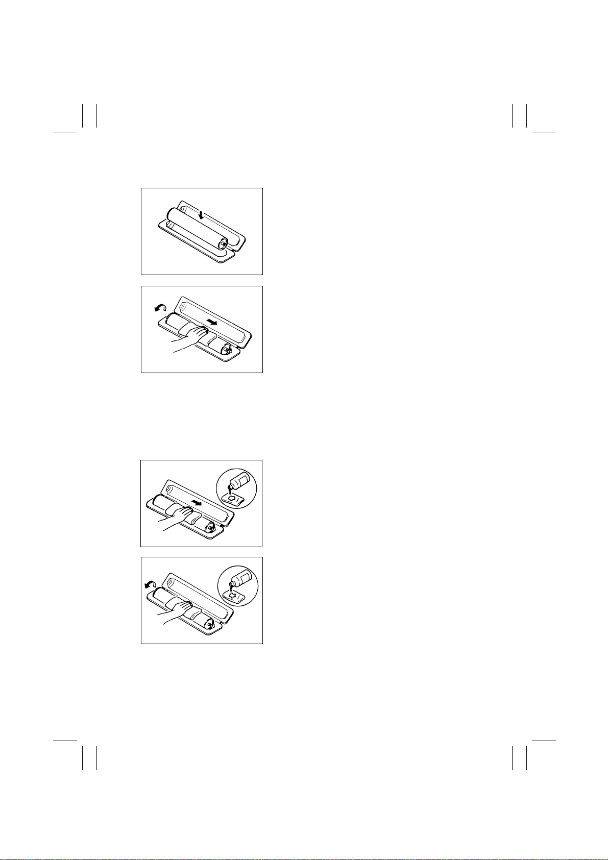
1. Place the PC Drum into one half of its container.
1076D001
2. Gently wipe the residual toner off the surface of the
PC Drum with a dry, Dust-Free Cotton Pad.
A. Rotate the PC Drum so that the area of its surface
on which the line of toner left by the Cleaning
Blade is present is facing straight up. Wipe the sur-
face in one continuous movement from the rear
edge of the PC Drum to the front edge and off the
surface of the PC Drum.
B. Rotate the PC Drum slightly and wipe the newly
exposed surface area with a CLEAN face of the
Dust-Free Cotton Pad. Repeat this procedure until
the entire surface of the PC Drum has been thor-
oughly cleaned.
✽
At this time, always use a CLEAN face of the dry
Dust-Free Cotton P ad until no toner is e vident on the
face of the Pad after wiping.
1076D002
3. Soak a small amount of either ethyl alcohol or iso-
propyl alcohol into a clean, unused Dust-Free Cot-
ton Pad which has been folded over into quarters.
Now, wipe the surface of the PC Drum in one con-
tinuous movement from its rear edge to its front
edge and off its surface one to two times.
✽
Never move the Pad back and forth.
1076D003
4. Using the SAME face of the Pad, repeat the proce-
dure explained in the latter half of step 3 until the
entire surface of the PC Drum has been wiped.
Always OVERLAP the areas when wiping. Two
complete turns of the PC Drum would be appropri-
ate for cleaning.
1076D004
FrameMaker Ver.5.5(PC) EP1054/EP1085/EP2030 DIS/REASSEMBLY, ADJUSTMENT
98.04.13
D-3
NOTES
•
The Organic Photoconductor Drum is softer than CdS and Selenium Drums and is there-
fore susceptible to scratches.
•
Even when the PC Drum is only locally dirtied, wipe the entire surface.
•
Do not expose the PC Drum to direct sunlight. Clean it as quickly as possible even under
interior illumination.
•
If dirt remains after cleaning, repeat the entire procedure from the beginning one more
time.
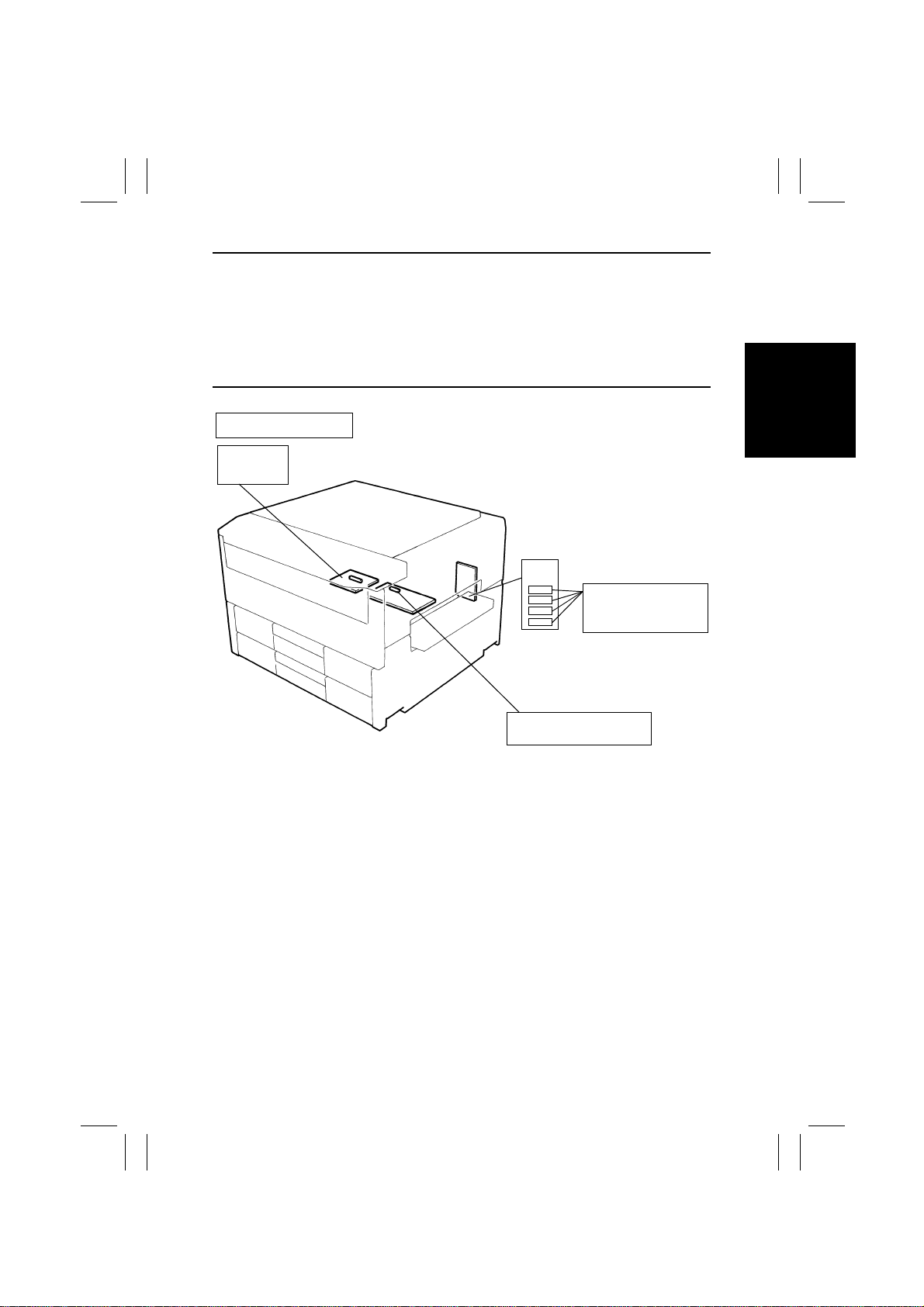
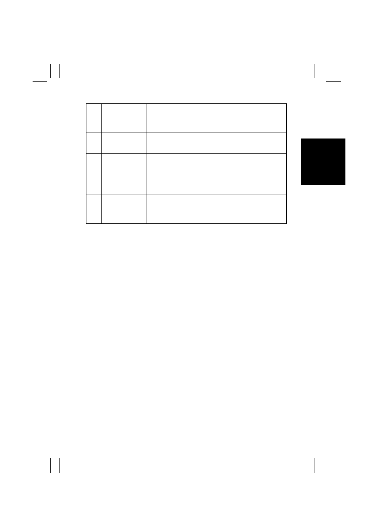
Identification of Fuses
PWB-D
250V 15A
Power Supply Board
PWB-C
250V 3A
Power Supply Unit PU2
125V 10A
1171D001AA
FrameMaker Ver.5.5(PC) EP1054/EP1085/EP2030 DIS/REASSEMBLY, ADJUSTMENT
98.04.13
D-4
Purpose of Application of Red Paint
Red paint is applied to the screws which cannot be readjusted, set, or reinstalled in he field.
The basic rule is not to remove or loosen the screws to which red paint is applied. In addi-
tion, be advised that, if two or more screws are designated as those which must not be
touched on a single part, only one representative screw may be marked with red paint.
Do not turn the variable resistors on boards for which no adjusting instructions are given in
“ADJUSTMENT.”
1-3. PARTS WHICH MUST NOT BE TOUCHED
(1) S crews
(2) Variable Resistors on Board
(3) Other Screws
Lower Pre-Image Transfer
Guide Plate (2 screws)
1139D078AA
Lens Rail height
setting screws (2)
1151D042AA
FrameMaker Ver.5.5(PC) EP1054/EP1085/EP2030 DIS/REASSEMBLY, ADJUSTMENT
98.04.13
D-5
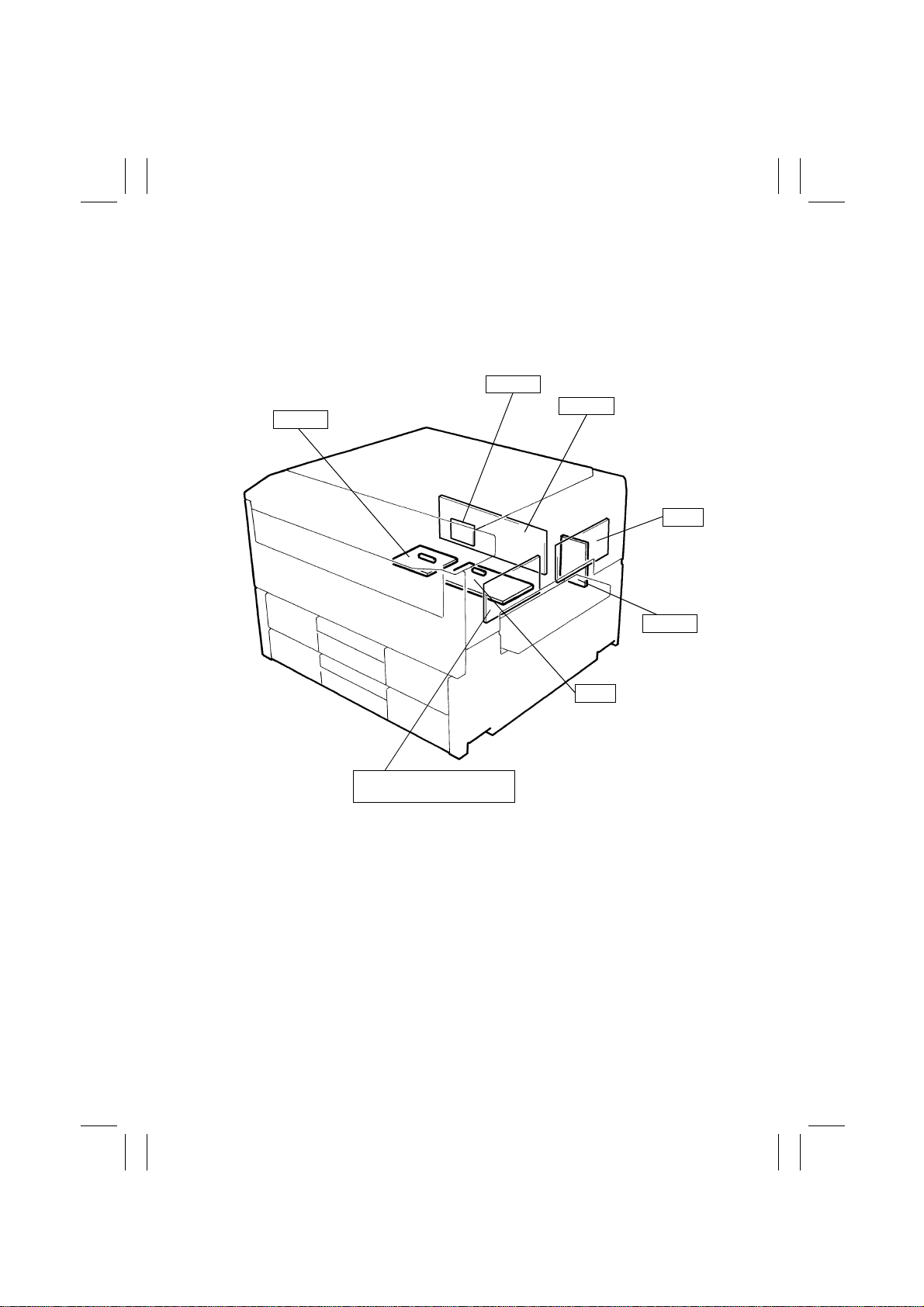
2 DISASSEMBLY/REASSEMBLY
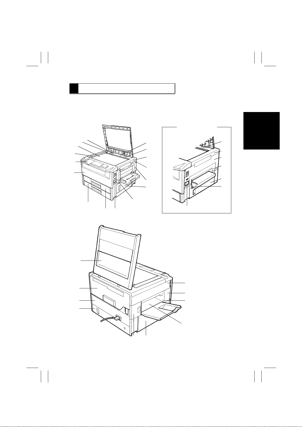
2-1. DOORS, COVERS, AND EXTERIOR PARTS: IDENTIFICA TION
AND REMOVAL PROCEDURES
2
1151D028AA
1151D001AA
1
16 (
✽
1)
14
13
12
11 (
✽
1)
9
8
7
6
5
3
18
19
20
21
22
23
24
15
<23 cpm copier>
4
10
<15/18 cpm copier>
8
9
10
11
12
13
14
1151D027AA
(
✽
1: 23 cpm copier only)
17
2526
FrameMaker Ver.5.5(PC) EP1054/EP1085/EP2030 DIS/REASSEMBLY, ADJUSTMENT
98.04.13
D-6
Remove the Original Cover by pulling it up.
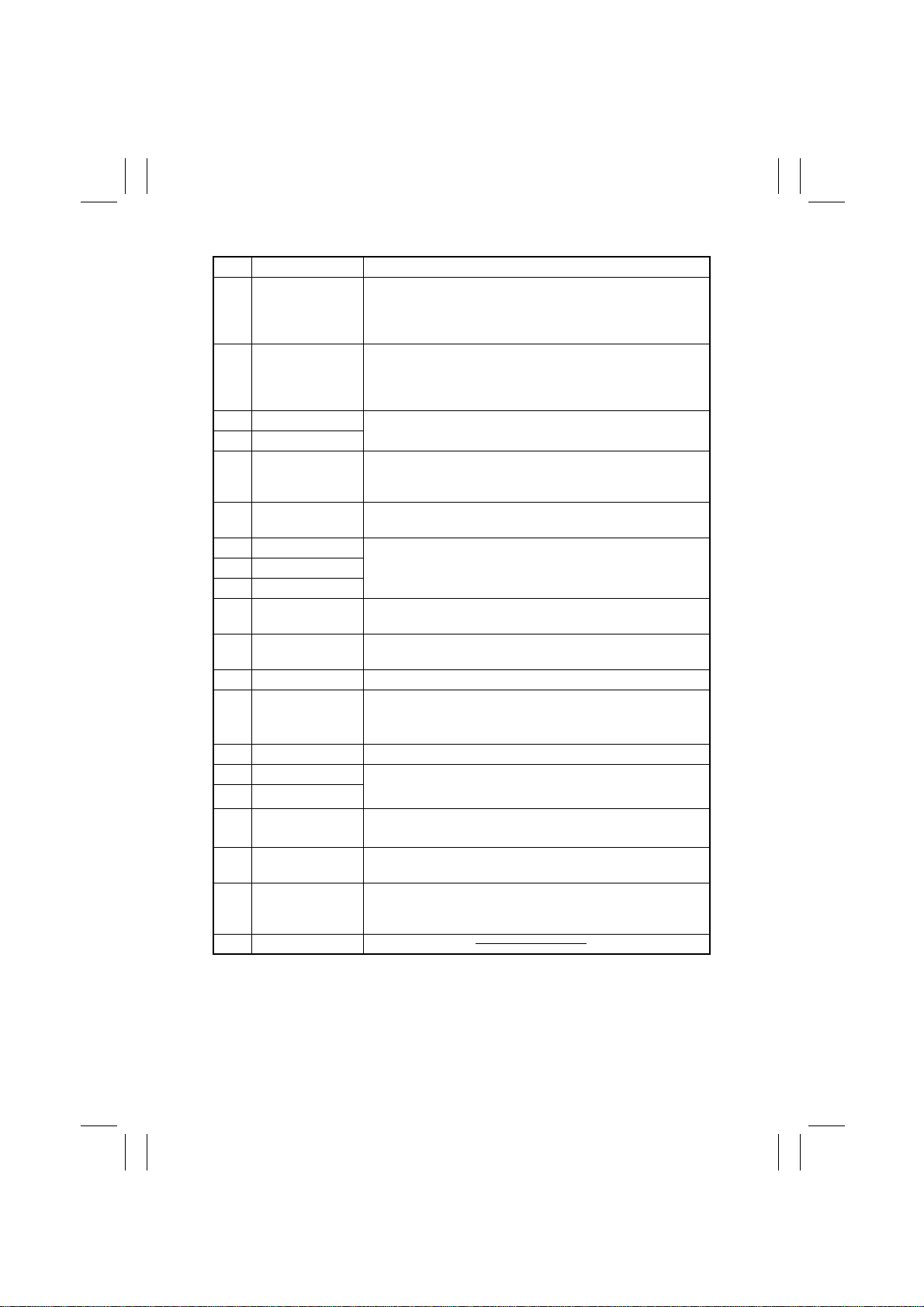
No. Part Name Removal Procedure
1 Front Door Swing down No.1.
→
Remove one screw that secures the Belt.
→
Remove two screws that secure the Front Door (only on
one side).
→
Slide the Door to the side from which the screws
have been removed.
2 Control Panel Swing down No.1.
→
Remove No.9.
→
Release and swing up
the Upper Half of the copier.
→
Remove No.21.
→
Remove
two screws that secure the control panel and loosen another
five screws that secure the control panel.
3 Original Scales Remove two screws that secure the Scales.
4 Original Glass
5 Rear Upper Cover
(Small)
Remove the Original Cover.
→
Release and swing up the
Upper Half of the copier .
→
Remove the Screw Co v er and one
mounting screw of No.5.
6 Left Hinge Cover Remove the Original Cover.
→
Remove one screw that
secures the Left Hinge Cover.
7 Rear Upper Cover Remove the Original Cover.
→
Remove No.6, 8 and 9.
→
Remove one screw that secures No.7.
8 Right Hinge Cover
9 Upper Right Cover
10 Right Cover Remove No.11.
→
Remove No. 9.
→
Remove two screws that
secure No.10.
11 Middle Right Cover Remove screws that secure No.11. (23 cpm copier: three/
15/18 cpm copier: four).
12 Right Door Open No.12 and remove it by lifting it up.
13 Multi Bypass Table
Mounting Bracket
✽
1
Remove two screws that secure the Multi Bypass Table
Mounting Bracket.
14 Counter Cover Remove No.14 by snapping if off.
15 1st Drawer Slide out the Drawer and remove one screw that secures the
Stopper at the rear left corner.
16
2nd Drawer
✽
2
17 Lower Rear Cover
✽
2
Remove two screws that secure the Lower Rear Cover.
18 Rear Cover Swing down No.1.
→
Release and swing up the Upper Half of
the copier.
→
Remove two screws that secure the Rear Cover.
19 Upper Rear Cover Swing down No.1.
→
Release and swing up the Upper Half of
the copier.
→
Remove three screws that secure the Upper
Rear Cover.
20 Original Cover
FrameMaker Ver.5.5(PC) EP1054/EP1085/EP2030 DIS/REASSEMBLY, ADJUSTMENT
98.04.13
D-7
✽
1: Multi Bypass Section: 15/18 cpm copier option
✽
2: 18/23 cpm copier only
No. Part Name Removal Procedure
21 Upper Left Cover Swing down No.1.
→
Release and swing up the Upper Half of
the copier.
→
Remove four screws that secure the Upper Left
Cover.
22 Middle Front Left
Cover
Swing down No.1.
→
Release and swing up the Upper Half of
the copier.
→
Remove one screw that secures the Middle
Front Left Cover.
23 Front Exit Cover Swing down No.1.
→
Release and swing up the Upper Half of
the copier.
→
Remove No.22.
→
Remove one screw that
secures the Front Exit Cover.
24 Rear Exit Cover Swing down No.1.
→
Release and swing up the Upper Half of
the copier.
→
Remove No.26.
→
Remove one screw that
secures the Rear Exit Cover.
25 Lower Left Cover Remove four screws that secure the Lower Left Cover.
26 Middle Rear Left
Cover
Swing down No.1.
→
Release and swing up the Upper Half of
the copier.
→
Remove one screw that secures the Middle Rear
Left Cover.
FrameMaker Ver.5.5(PC) EP1054/EP1085/EP2030 DIS/REASSEMBLY, ADJUSTMENT
98.04.13
D-8
•
When removing a PWB, first go over “PRECAUTIONS FOR HANDLING THE PWBs”
contained in SWITCHES ON PWBs and use the removal procedures given on the next
page.
•
Replacement of a PWB may call for readjustments or resetting of particular items.
•
The removal procedures given on the ne xt page omit the steps to unplug connectors and
remove the PWB from the PWB support.
2-2. REMOVAL OF PWBs
PWB-D
1174D001AA
PWB-Y
PWB-A
PU1
PU2
PWB-C
PWB-E (15/18 cpm copier)
PWB-F (23 cpm copier)

FrameMaker Ver.5.5(PC) EP1054/EP1085/EP2030 DIS/REASSEMBLY, ADJUSTMENT
98.04.13
D-9
✽
Details of Readjustments/Resetting Involved In Replacement of PWB-Y, UN2 and UN3.
•
When PWB-Y is replaced:
Carry out Memory Clear and then make the Tech. Rep. Program, User's Choice, and
Adjust settings again.
•
When UN2 is replaced: (18/23 cpm copier only)
Adjust the Original Size Detecting Board.
•
When UN3 is replaced:
Discard the developer which had been used until UN3 was replaced, charge the Devel-
oping Unit with fresh starter, and adjust ATDC.
Symbol Part Name Removal Procedure
PWB-A Master Board Open 1.
→
Release and swing up the Upper Half of
the copier.
→
Remove 19.
PWB-C Power Supply Board Open 1.
→
Release and swing up the Upper Half of
the copier.
→
Remove 17 (18/23 cpm copier only), 18,
and 19.
→
Remove four screws that secure the Power
Supply Unit Cover.
PWB-D Noise Filter Board
PWB-E
(15/18 cpm
copier)
Motor Drive Board Open 1 and 12.
→
Remove 9, 10, and 11.
PWB-F
(23 cpm
copier)
Motor Drive Board Open 1.
→
Remove 11.
→
Remove 9 and 10.
→
Remove the Multi Bypass Unit.
PWB-H AE Sensor Board Remove 3 and 4.
→
Remove the optical cover.
PWB-P Control Panel Open 1.
→
Remove 9.
→
Release and swing up the
Upper Half of the copier.
→
Remove 21.
→
Remove
seven screws that secure Control Panel.
PWB-Y RAM Board Open 1.
→
Release and swing up the Upper Half of
the copier.
→
Remove 19.
PU1 Power Supply Unit <18/23 cpm copier>
Open 1.
→
Remove 11.
→
Remove 9 and 10.
→
Remove the Multi Bypass Unit.
<15 cpm copier>
Open 1 and 12.
→
Remove 9, 10, and 11.
PU2 DC Power Supply
Unit
Open 1.
→
Release and swing up the Upper Half of
the copier.
→
Remove 17 (18/23 cpm copier only) and
18.
HV1 High Voltage Unit Open 1.
→
Release and swing up the Upper Half of
the copier.
→
Remove 19.
→
Remove PWB-A.
UN2
(18/23 cpm
copier only)
Original Size Detect-
ing Board
Remove 3 and 4.
→
Remove the optical cover.
UN3 ATDC Sensor Open 1.
→
Release and swing up the Upper Half of
the copier.
→
Take out the I/U.
→
Remove two screws
that secure the Synchronizing Roller Guide Unit.
FrameMaker Ver.5.5(PC) EP1054/EP1085/EP2030 DIS/REASSEMBLY, ADJUSTMENT
98.04.13
D-10
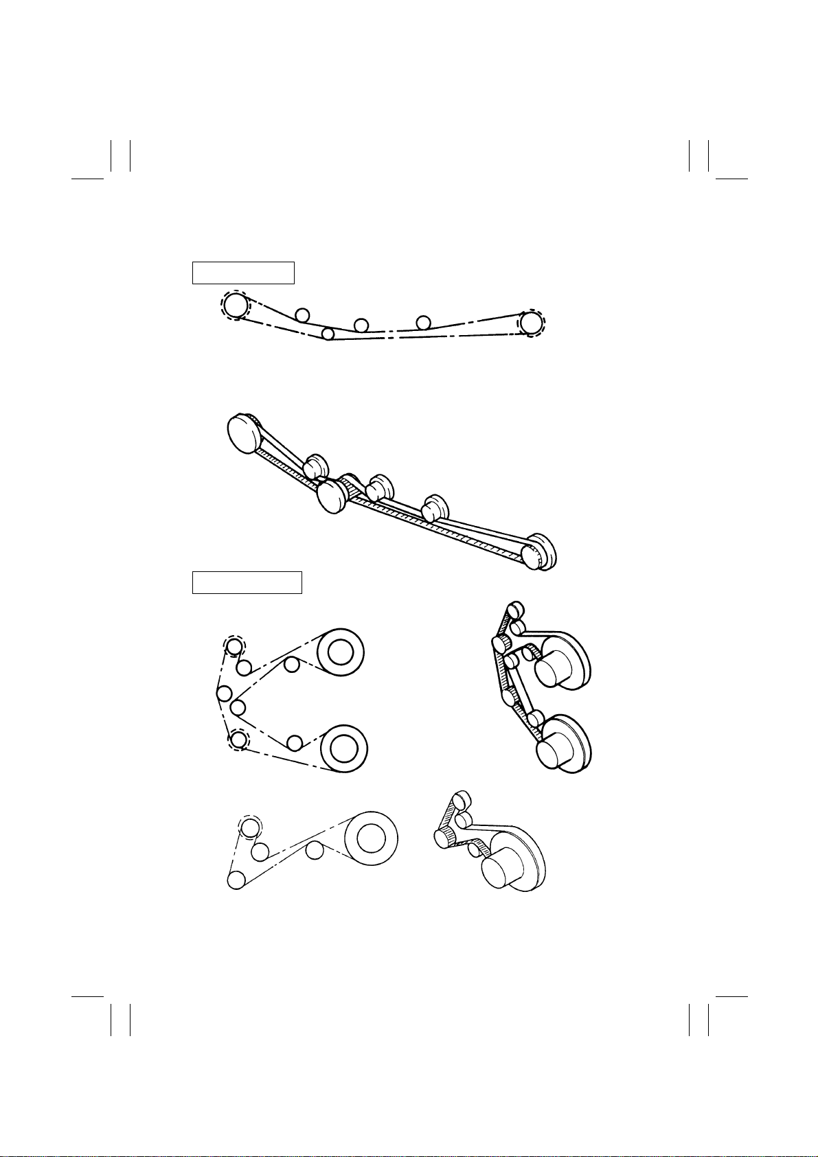
•
Rear View
2-3. BELT INSTALLATIONS
1151D052AB
1151D050AA
1142D005AA
<18/23 cpm copier>
<15 cpm copier>
Drive/Suction Unit
Paper Take-Up Unit
FrameMaker Ver.5.5(PC) EP1054/EP1085/EP2030 DIS/REASSEMBLY, ADJUSTMENT
98.04.13
D-11
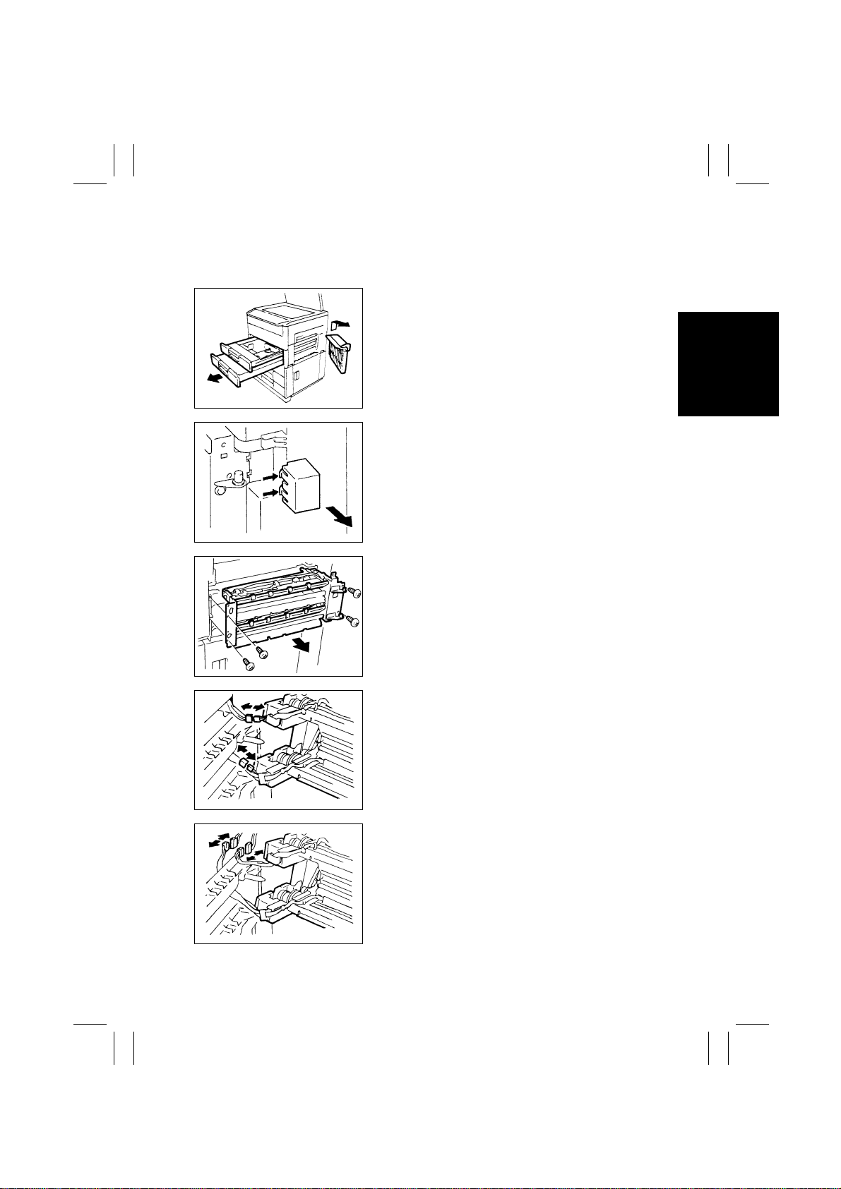
2-4. PAPER TAKE-UP/TRANSPORT SECTIONS
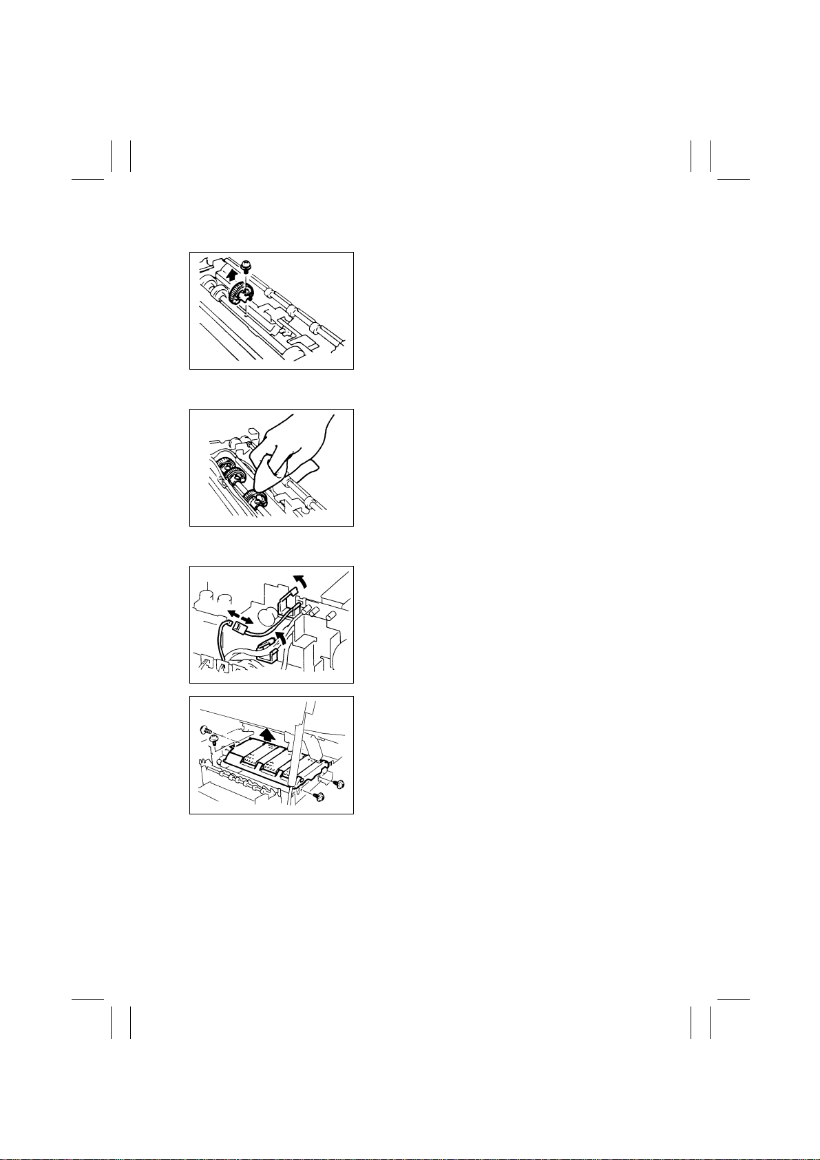
(1) Removal of the Paper Take-Up Unit
1. Remove the Multi Bypass Table. (15/18 cpm
copier: OPTION) See p. D-15. (NO 1 ~ 7)
2. Slide out the 1st and 2nd (23 cpm copier only)
Drawers.
1139D084AA
3. Press the tabs at the two places indicated by the
arrow and, at the same time, remove the cover.
(15/18 cpm copier only)
1142D007AA
4. Remove screws and the Paper Take-Up Unit. (23
cpm copier: four screws/15/18 cpm copier: five
screws)
1151D020AA
1139D086AA
5. Unplug the connectors from the solenoids on the
Paper Take-Up Unit. (23 cpm copier: two connec-
tors/15/18 cpm copier: one connector)
1139D238AA
6. Remove the Rear and Rear Upper covers.
7. Remove the DC Power Supply Unit.
8. Remove the harness from the wiring saddle.
9. Unplug the connectors (23 cpm copier: two con-
nectors/15/18 cpm copier: one connector).
FrameMaker Ver.5.5(PC) EP1054/EP1085/EP2030 DIS/REASSEMBLY, ADJUSTMENT
98.04.13
D-12
(2) Removal of the Paper Take-Up Rolls
(3) Cleaning of the Paper Take-Up Rolls
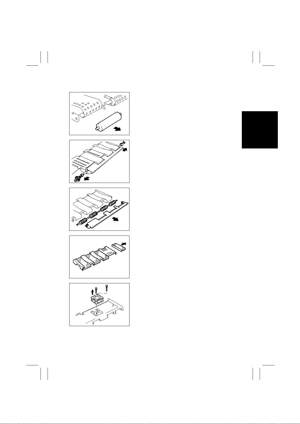
(4) Rem oval of the Suction Unit
1. Remove one screw to remove the Paper Take-Up
Roll.
1139D088AA
1. Remove the Paper Take-Up Unit from the copier.
2. Using a soft cloth dampened with alcohol, wipe
clean the Paper Take-Up Rolls.
1139D089AA
1. Remove the Fusing Unit. (See p. D-40.)
2. Unplug the Suction Fan connector and remove the
wire from the clamp.
1151D029AA
3. Remove four screws to remove the Suction Unit.
1151D030AA
FrameMaker Ver.5.5(PC) EP1054/EP1085/EP2030 DIS/REASSEMBLY, ADJUSTMENT
98.04.13
D-13
(5) Disassembly of the Suction Unit
1. Remove the four Suction Drive Rolls and six bush-
ings by pulling them in the direction of the arrow.
1151D004AA
2. Snap off the three E-rings from the Suction Drive
Unit.
3. Remove the gear and bushings.
1139D094AA
4. Remove the Pre-Fusing Guide Plate.
5. Remove the Suction Drive Unit.
1151D005AA
6. Remove the four belts.
1151D006AA
7. Remove the Suction Fan.
1151D009AA
FrameMaker Ver.5.5(PC) EP1054/EP1085/EP2030 DIS/REASSEMBLY, ADJUSTMENT
98.04.13
D-14
Remark
•
The replacement springs are installed on the underside of the 2nd Drawer.
(6) Replacement of the Paper Lifting Springs (2nd Drawer): 23 cpm copier only
1139U044AA
1. Remove the Stoppers of the 2nd Drawer and the
2nd Drawer.
1136P243AA
2. Remove one screw and the Edge Guide Unit.
1151D043AA
3. Remove the F ront Separator Finger by remo ving its
pin.
1139U045AA
4. Raise the Paper Lifting Plate Unit and replace the
Paper Lifting Springs. See p. D-61.
1139U047AA

FrameMaker Ver.5.5(PC) EP1054/EP1085/EP2030 DIS/REASSEMBLY, ADJUSTMENT
98.04.13
D-15
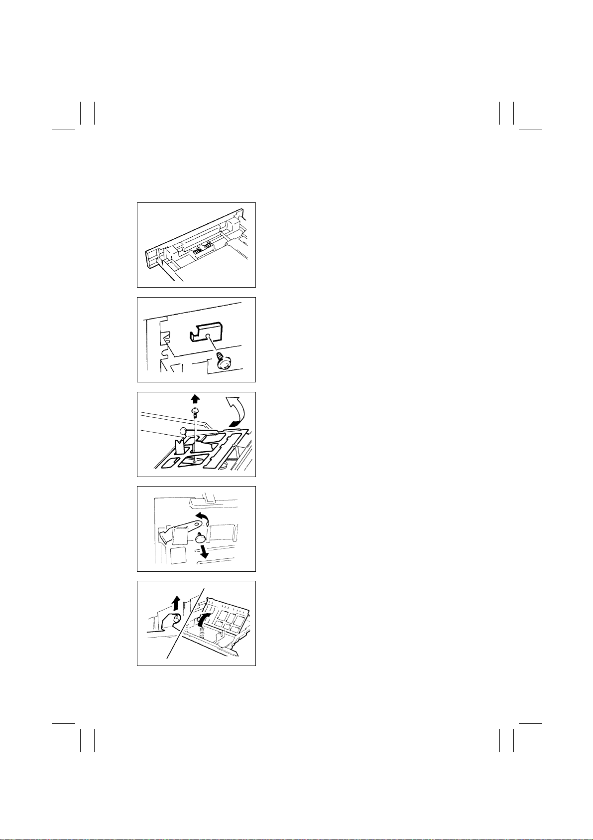
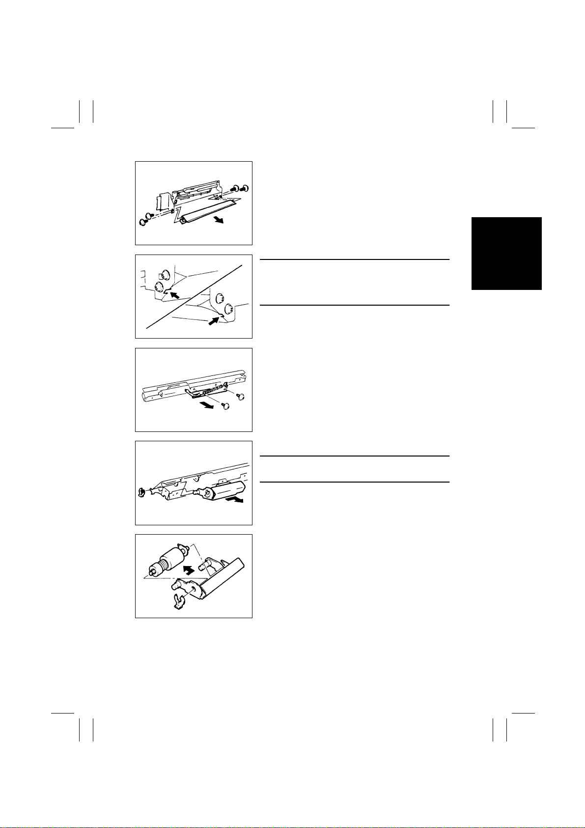
(7) Disassembly of the Multi Bypass Table (15/18 cpm copier: OPTION)
1139D099AA
1. Remove the Right Door.
2. Remove three screws and the Large Cover.
4425U408AA
3. Remove one screw and the Small Cover.
1139D227AA
4. Remove three screws and the Guide Lever Unit.
1139D222AA
1139D223AA
FrameMaker Ver.5.5(PC) EP1054/EP1085/EP2030 DIS/REASSEMBLY, ADJUSTMENT
98.04.13
D-16
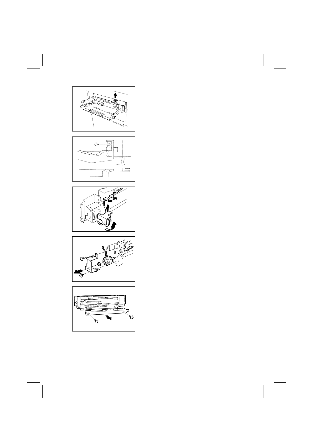
5. Remove four screws and the Multi Bypass Table.
6. Unplug the Multi Bypass Table connector.
1139D240AA
7. Remove one screw and the Multi Bypass Table.
1139D225AA
8. Unplug one connector.
9. Remove the Tension Unit.
1151D018AA
10. Remove two screws and the Clutch Mounting
Bracket.
1139D101AA
1139D102AA
11. Remove two screws and the Lower Guide.
FrameMaker Ver.5.5(PC) EP1054/EP1085/EP2030 DIS/REASSEMBLY, ADJUSTMENT
98.04.13
D-17
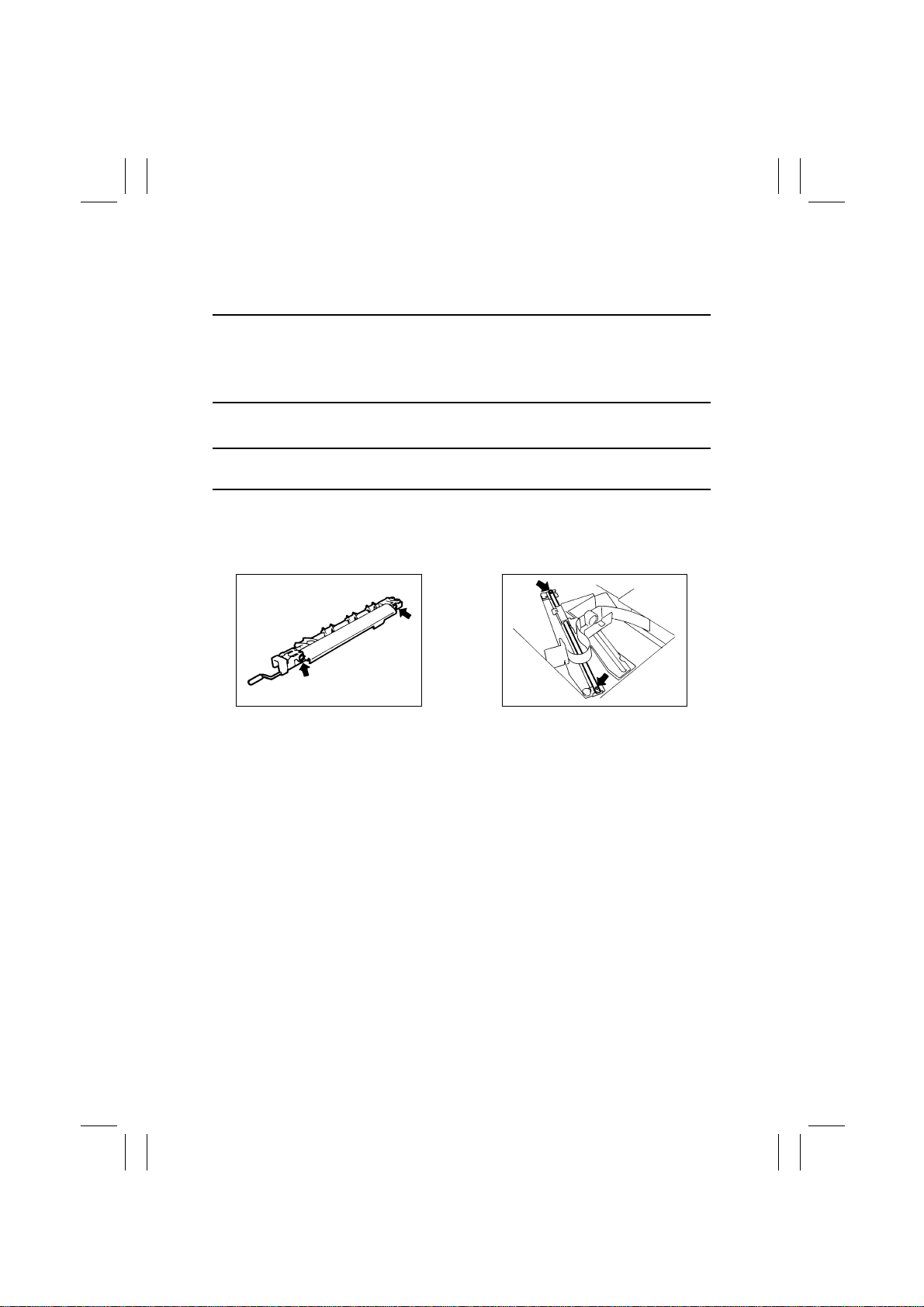
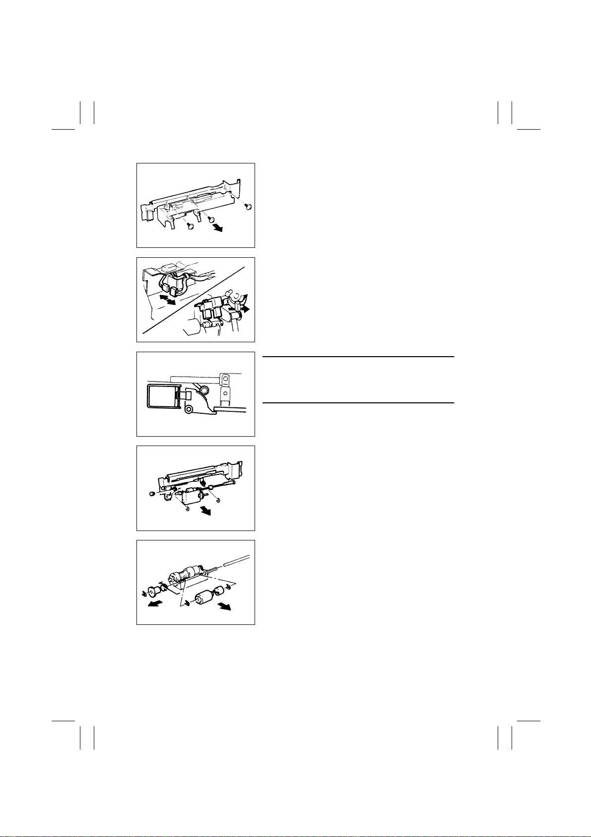
12. Remove four screws and the Separator Guide
Plate Unit.
1139D103AA
1139D104AA
NOTE
When reinstalling the Separator Guide Plate Unit,
press the parts shown on the left up against the copier
frame (both at front and rear).
13. Remove two screws and the Lev er.
1139D105AA
14. Snap off one C-clip and remove the Separator Unit.
NOTE
•
Please use tweezers when reinstalling the C-clip.
1139D106AA
1139D107AA
15. Snap off one C-clip and remove the Separator Roll
Assy .
FrameMaker Ver.5.5(PC) EP1054/EP1085/EP2030 DIS/REASSEMBLY, ADJUSTMENT
98.04.13
D-18
16. Remove three screws and the Solenoid Mounting
Bracket.
1139D108AA
1139D109AA
17. Unplug one solenoid connector.
18. Unplug one photosensor connector and remove
the harness from the clamp.
1139D110AA
NOTE
When reinstalling the Solenoid Mounting Bracket,
make sure that the Solenoid is in the deenergized
position.
19. Snap off the two C-clips to remove the Paper Take-
Up Roll Unit.
1139D111AA
1139D112AA
20. Snap off the three C-clips to remove the Paper
Feed Roll.

FrameMaker Ver.5.5(PC) EP1054/EP1085/EP2030 DIS/REASSEMBLY, ADJUSTMENT
98.04.13
D-19
21. Snap off one C-clip and remove the Paper Take-Up
Roll.
1139D113AA
 Loading...