


 Loading...
3121299 |
660SJ/600S |
3 |
|
TABLE OF CONTENTS |
|
SECTION 1 - FRAME........................................................................................................................................................................... |
|
7 |
FIGURE 1-1. AXLE INSTALLATION ................................................................................................................................................ |
|
8 |
FIGURE 1-2. STEERING INSTALLATION WITHOUT TOW PACKAGE ........................................................................................ |
10 |
|
FIGURE 1-3. STEERING INSTALLATION WITH TOW PACKAGE................................................................................................ |
14 |
|
FIGURE 1-4. TIRE AND WHEEL DRIVE INSTALLATIONS |
........................................................................................................... |
18 |
FIGURE 1-5. DRIVE HUB ASSEMBLY .......................................................................................................................................... |
|
22 |
FIGURE 1-6. DRIVE MOTOR ASSEMBLY .................................................................................................................................... |
|
26 |
FIGURE 1-7. DRIVE VALVES AND SHIELDS INSTALLATION (FRAME MOUNTED) .................................................................. |
28 |
|
FIGURE 1-8. TOW PACKAGE INSTALLATION (OPTIONAL) ....................................................................................................... |
32 |
|
SECTION 2 - TURNTABLE................................................................................................................................................................ |
|
35 |
FIGURE 2-1. CONTROL VALVES INSTALLATIONS..................................................................................................................... |
|
36 |
FIGURE 2-2. CONTROL VALVES INSTALLATIONS..................................................................................................................... |
|
40 |
FIGURE 2-3. MAIN CONTROL VALVE ASSEMBLY...................................................................................................................... |
|
42 |
FIGURE 2-4. MAIN CONTROL VALVE ASSEMBLY...................................................................................................................... |
|
46 |
FIGURE 2-5. ACCESSORY VALVE ASSEMBLY........................................................................................................................... |
|
50 |
FIGURE 2-6. SWING DRIVE, TURNTABLE BEARING AND LOCK INSTALLATIONS.................................................................. |
52 |
|
FIGURE 2-7. SWING MOTOR/HUB ASSEMBLY........................................................................................................................... |
|
54 |
FIGURE 2-8. DEUTZ D2011 ENGINE INSTALLATION ................................................................................................................. |
|
58 |
FIGURE 2-9. DEUTZ TD2.9L4 ENGINE INSTALLATION .............................................................................................................. |
|
68 |
FIGURE 2-10. GM ENGINE INSTALLATION ................................................................................................................................. |
|
80 |
FIGURE 2-11. PISTON PUMP ASSEMBLY ................................................................................................................................... |
|
86 |
FIGURE 2-12. GEAR PUMP ASSEMBLY ...................................................................................................................................... |
|
92 |
FIGURE 2-13. TANK INSTALLATIONS.......................................................................................................................................... |
|
94 |
FIGURE 2-14. ROTARY COUPLING INSTALLATION ................................................................................................................... |
|
98 |
FIGURE 2-15. GROUND CONTROL BOX ASSEMBLY (FIBERGLASS BOX) ............................................................................ |
102 |
|
FIGURE 2-16. GROUND CONTROL BOX ASSEMBLY (STEEL BOX)........................................................................................ |
106 |
|
FIGURE 2-17. ELECTRICAL OPTIONS INSTALLATION (TURNTABLE MOUNTED)................................................................. |
110 |
|
FIGURE 2-18. ENGINE TRAY JACK INSTALLATION (OPTIONAL)............................................................................................ |
114 |
|
FIGURE 2-19. HOODS (ABS) AND LIFTING PLATE INSTALLATIONS ...................................................................................... |
116 |
|
FIGURE 2-20. HOODS (STEEL) AND LIFTING PLATE INSTALLATIONS (DEUTZ D2011 AND GM ENGINES)....................... |
122 |
|
FIGURE 2-21. HOODS (STEEL) AND LIFTING PLATE INSTALLATIONS (DEUTZ TD2.9L4 ENGINES) ................................... |
128 |
|
FIGURE 2-22. 7500W SKYPOWER GENERATOR INSTALLATION - DEUTZ ENGINE (OPTIONAL)........................................ |
134 |
|
FIGURE 2-23. 7500W SKYPOWER GENERATOR INSTALLATION - GM ENGINE (OPTIONAL) .............................................. |
140 |
|
SECTION 3 - BOOM ........................................................................................................................................................................ |
|
145 |
FIGURE 3-1. BOOM INSTALLATION - 600S ............................................................................................................................... |
|
146 |
FIGURE 3-2. BOOM INSTALLATION - 660SJ ............................................................................................................................. |
|
150 |
FIGURE 3-3. MAIN BOOM ASSEMBLIES ................................................................................................................................... |
|
156 |
FIGURE 3-4. ROTATOR ASSEMBLIES....................................................................................................................................... |
|
160 |
FIGURE 3-5. CONTROL VALVE INSTALLATION (BOOM) |
......................................................................................................... |
162 |
FIGURE 3-6. POWER TRACK INSTALLATIONS......................................................................................................................... |
|
166 |
SECTION 4 - PLATFORM................................................................................................................................................................ |
|
169 |
FIGURE 4-1. PLATFORM COMPONENTS INSTALLATION ....................................................................................................... |
170 |
|
FIGURE 4-2. PLATFORM COMPONENTS INSTALLATION (FALL ARREST PLATFORM)........................................................ |
174 |
|
FIGURE 4-3. PLATFORM CONSOLE ASSEMBLY...................................................................................................................... |
|
176 |
FIGURE 4-4. CONTROLLER ASSEMBLY (LIFT AND SWING) ................................................................................................... |
180 |
|
FIGURE 4-5. CONTROLLER ASSEMBLY (DRIVE AND STEER)................................................................................................ |
182 |
|
FIGURE 4-6. SOFT TOUCH SYSTEM INSTALLATION (OPTIONAL) ......................................................................................... |
184 |
|
SECTION 5 - CYLINDER ................................................................................................................................................................. |
|
187 |
FIGURE 5-1. AXLE LOCKOUT CYLINDER ASSEMBLY ............................................................................................................. |
|
188 |
FIGURE 5-2. PLATFORM LEVEL SLAVE CYLINDER ASSEMBLY............................................................................................. |
190 |
|
FIGURE 5-3. MAIN LIFT CYLINDER ASSEMBLY ....................................................................................................................... |
|
194 |
FIGURE 5-4. JIB LIFT CYLINDER ASSEMBLY - 660SJ.............................................................................................................. |
|
196 |
FIGURE 5-5. MASTER CYLINDER ASSEMBLY.......................................................................................................................... |
|
198 |
FIGURE 5-6. STEER CYLINDER ASSEMBLY............................................................................................................................. |
|
200 |
FIGURE 5-7. TELESCOPE CYLINDER ASSEMBLY ................................................................................................................... |
|
202 |
SECTION 6 - HYDRAULIC .............................................................................................................................................................. |
|
205 |
3121299 |
660SJ/600S |
5 |
TABLE OF CONTENTS |
|
FIGURE 6-1. HYDRAULIC DIAGRAM - AXLE LOCKOUT............................................................................................................ |
206 |
FIGURE 6-2. HYDRAULIC DIAGRAM - DRIVE AND STEER (2WD/2WS)................................................................................... |
208 |
FIGURE 6-3. HYDRAULIC DIAGRAM - DRIVE AND STEER (4WD/2WS)................................................................................... |
210 |
FIGURE 6-4. HYDRAULIC DIAGRAM - STANDARD ................................................................................................................... |
212 |
FIGURE 6-5. HYDRAULIC DIAGRAM - STANDARD ................................................................................................................... |
216 |
FIGURE 6-6. HYDRAULIC DIAGRAM LIST.................................................................................................................................. |
220 |
SECTION 7 - ELECTRICAL.............................................................................................................................................................. |
221 |
FIGURE 7-1. ELECTRICAL DIAGRAM LIST ................................................................................................................................ |
222 |
FIGURE 7-2. HARNESS COMPONENTS INSTALLATION .......................................................................................................... |
224 |
FIGURE 7-3. HARNESS COMPONENTS INSTALLATION .......................................................................................................... |
242 |
SECTION 8 - DECALS ..................................................................................................................................................................... |
261 |
FIGURE 8-1. DECAL INSTALLATION (ANSI SPEC).................................................................................................................... |
262 |
FIGURE 8-2. DECAL INSTALLATION (COUNTRY SPEC) .......................................................................................................... |
266 |
FIGURE 8-3. DECAL INSTALLATION (AUSTRALIAN AND CE SPEC) ....................................................................................... |
272 |
SECTION 9 - RECOMMENDED SERVICE PARTS STOCK ............................................................................................................ |
275 |
FIGURE 9-1. MODEL 600SJ/660SJ STANDARD PARTS ............................................................................................................ |
276 |
FIGURE 9-2. MODEL 600SJ/660SJ VARIABLE PARTS .............................................................................................................. |
278 |
SECTION 10 - SPECIAL OPTIONS ................................................................................................................................................. |
279 |
FIGURE 10-1. SPECIAL OPTIONS .............................................................................................................................................. |
280 |
PART NUMBER INDEX.................................................................................................................................................................... |
287 |
6 |
660SJ/600S |
3121299 |
SECTION 1 - FRAME
SECTION 1 - FRAME
3121299 |
660SJ/600S |
7 |
SECTION 1 - FRAME
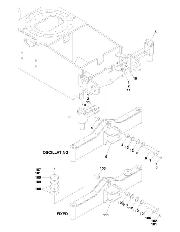
FIGURE 1-1. AXLE INSTALLATION
8 |
660SJ/600S |
3121299 |
|
|
|
|
SECTION 1 - FRAME |
||
|
|
FIGURE 1-1. AXLE INSTALLATION |
|
|
|
|
|
|
|
|
|
|
|
ITEM |
PART NUMBER |
QTY |
DESCRIPTION |
|
REV |
|
|
|
|
|
|
|
|
|
|
Ref |
AXLE INSTALLATIONS - OSCILLATING |
|
|
|
|
1001148168 |
Ref |
Axle without Tow Package |
|
C |
|
|
1001148170 |
Ref |
Axle with Tow Package |
|
C |
|
1 |
0100011 |
AR |
Compound, Locking |
|
|
|
2 |
0641814 |
8 |
Bolt 1/2in-13NC x 1-3/4in |
|
|
|
3 |
0642012 |
1 |
Bolt 5/8in-11NC x 1-1/2in |
|
|
|
4 |
0961950 |
2 |
Bearing |
|
|
|
5 |
1684465 |
2 |
Lockout Cylinder Assembly (See CYLINDER SECTION for |
|
|
|
|
|
|
Breakdown) |
|
|
|
6 |
3423184 |
1 |
Pin |
|
|
|
7 |
3841258 |
1 |
Keeper, Pin |
|
|
|
8 |
4740158 |
AR |
Thrustwasher (1/4in Thick) |
|
|
|
9 |
|
Ref |
Axle Weldment Options: |
|
|
|
9 |
1001148171 |
1 |
Axle without Tow Package |
|
|
|
9 |
1001148172 |
1 |
Axle with Tow Package (Not Shown) |
|
|
|
10 |
4891800 |
8 |
Flatwasher 1/2in Hardened |
|
|
|
11 |
0100038 |
AR |
Primer, Locking |
|
|
|
12 |
4740229 |
AR |
Thrustwasher (1/8in Thick) |
|
|
|
13 |
4071101 |
AR |
Shim (18Ga) |
|
|
|
|
1001148169 |
Ref |
AXLE INSTALLATIONS - FIXED |
|
C |
|
101 |
0100011 |
AR |
Compound, Locking |
|
|
|
102 |
0642012 |
1 |
Bolt 5/8in-11NC x 1-1/2in |
|
|
|
103 |
0961950 |
2 |
Bearing |
|
|
|
104 |
3423184 |
1 |
Pin, Pivot |
|
|
|
105 |
3539877 |
2 |
Plate, Stop |
|
|
|
106 |
3841258 |
1 |
Keeper, Pin |
|
|
|
107 |
3931840 |
2 |
Screw 1/2in-13NC x 2-1/2in |
|
|
|
108 |
4070944 |
6 |
Shim (.06) |
|
|
|
109 |
4070945 |
2 |
Shim (.25) |
|
|
|
110 |
4740158 |
AR |
Thrustwasher |
|
|
|
111 |
1001148171 |
1 |
Axle Weldment |
|
|
|
112 |
4071101 |
AR |
Shim (18Ga) |
|
|
|
113 |
4740229 |
AR |
Thrustwasher (1/8in Thick) |
|
|
|
3121299 |
660SJ/600S |
9 |

SECTION 1 - FRAME
FIGURE 1-2. STEERING INSTALLATION WITHOUT TOW PACKAGE
10 |
660SJ/600S |
3121299 |
SECTION 1 - FRAME
FIGURE 1-2. STEERING INSTALLATION WITHOUT TOW PACKAGE
|
ITEM |
PART NUMBER |
QTY |
DESCRIPTION |
REV |
|
|
|
|
|
|
|
|
|
|
|
Ref |
4WD STEERING INSTALLATION |
|
|
|
|
1001148162 |
Ref |
4WD/2WS |
C |
|
|
|
1001148163 |
Ref |
4WD/4WS (Note: Double qty for 4WD/4WS Machines) |
B |
|
|
1 |
0100011 |
AR |
Compound, Locking |
|
|
|
2 |
0641608 |
6 |
Bolt 3/8in-16NC x 1in |
|
|
|
3 |
1001097242 |
2 |
Steer Cylinder Assembly (See CYLINDER SECTION for |
|
|
|
|
|
|
Breakdown) |
|
|
|
4 |
0642012 |
2 |
Bolt 5/8in-11NC x 1-1/2in |
|
|
|
5 |
0962356 |
2 |
Bushing |
|
|
|
6 |
0962131 |
4 |
Bushing |
|
|
|
8 |
3422326 |
2 |
Pin |
|
|
|
9 |
3422900 |
2 |
Kingpin |
|
|
|
10 |
3422902 |
2 |
Pin |
|
|
|
11 |
3422903 |
2 |
Pin |
|
|
|
12 |
3841143 |
6 |
Keeper, Pin |
|
|
|
13 |
3841258 |
2 |
Keeper, Pin |
|
|
|
14 |
1001155574 |
1 |
Tie-Rod |
|
|
|
15 |
1001099387 |
1 |
Spindle - Left Side |
|
|
|
16 |
1001099196 |
1 |
Spindle - Right Side |
|
|
|
17 |
4740111 |
6 |
Thrustwasher |
|
|
|
18 |
4740256 |
2 |
Thrustwasher |
|
|
|
19 |
4740463 |
2 |
Thrustwasher |
|
|
|
|
1001148161 |
Ref |
2WD STEERING INSTALLATION |
C |
|
|
101 |
0100011 |
AR |
Compound, Locking |
|
|
|
104 |
0641608 |
6 |
Bolt 3/8in-16NC x 1in |
|
|
|
106 |
0642012 |
2 |
Bolt 5/8in-11NC x 1-1/2in |
|
|
|
108 |
0962356 |
2 |
Bushing |
|
|
|
109 |
0962131 |
4 |
Bushing |
|
|
|
111 |
1001097242 |
2 |
Steer Cylinder Assembly (See CYLINDER SECTION for |
|
|
|
|
|
|
Breakdown) |
|
|
|
112 |
4130410 |
2 |
Hub Assembly (See Items 201-212 for Breakdown) |
|
|
|
114 |
3422326 |
2 |
Pin |
|
|
|
115 |
3422900 |
2 |
Kingpin |
|
|
|
116 |
3422902 |
2 |
Pin |
|
|
|
117 |
3422903 |
2 |
Pin |
|
|
|
118 |
3841143 |
6 |
Keeper, Pin |
|
|
|
119 |
3841258 |
2 |
Keeper, Pin |
|
|
|
120 |
1001155574 |
1 |
Tie-Rod |
|
|
|
122 |
1001099387 |
1 |
Spindle - Left Side |
|
|
|
123 |
1001099196 |
1 |
Spindle - Right Side |
|
|
|
124 |
4740111 |
6 |
Thrustwasher |
|
|
|
125 |
4740256 |
2 |
Thrustwasher |
|
|
|
127 |
4740463 |
2 |
Thrustwasher |
|
|
|
130 |
0682020 |
12 |
Bolt 5/8in-11NC x 2-1/2in (Grade 8) |
|
|
|
131 |
3272001 |
12 |
Nut 5/8in-11NC (Grade 8) |
|
|
|
132 |
4892000 |
24 |
Flatwasher 5/8in Hardened |
|
|
|
|
4130409 |
Ref |
HUB ASSEMBLY |
C |
|
|
201 |
0440170 |
2 |
Cone, Bearing |
|
|
|
202 |
0440171 |
2 |
Cup, Bearing |
|
|
|
203 |
0721003 |
3 |
Bolt #10-24NC x 3/8in |
|
|
3121299 |
|
|
660SJ/600S |
11 |
||
SECTION 1 - FRAME
ITEM |
PART NUMBER |
QTY |
DESCRIPTION |
REV |
|
|
|
|
|
204 |
1120304 |
1 |
Cap, Hub |
|
205 |
2780271 |
1 |
Hub |
|
205A |
0630490 |
9 |
Stud, Wheel |
|
206 |
3323403 |
1 |
Nut, Slotted 1-1/2in -12NF |
|
207 |
3451010 |
1 |
Pin, Cotter 5/8in x 2-1/2in |
|
208 |
3960343 |
1 |
Seal, Grease |
|
209 |
4130409 |
1 |
Adapter, Spindle |
|
210 |
4740283 |
1 |
Flatwasher, Hardened |
|
211 |
4761000 |
3 |
Lockwasher #10 |
|
212 |
3020017 |
AR |
Grease, Bearing |
|
12 |
660SJ/600S |
3121299 |
SECTION 1 - FRAME
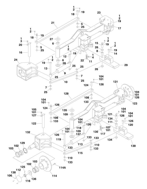
FIGURE 1-3. STEERING INSTALLATION WITH TOW PACKAGE
14 |
660SJ/600S |
3121299 |
|
|
|
|
SECTION 1 - FRAME |
||
|
|
FIGURE 1-3. STEERING INSTALLATION WITH TOW PACKAGE |
|
|
||
|
|
|
|
|
|
|
|
ITEM |
PART NUMBER |
QTY |
DESCRIPTION |
REV |
|
|
|
|
|
|
|
|
|
|
|
Ref |
4WD STEERING INSTALLATION |
|
|
|
|
|
Ref |
USA Built Machines: |
|
|
|
|
1001148164 |
Ref |
4WD/2WS |
C |
|
|
|
1001148166 |
Ref |
4WD/4WS (Note: Double qty for 4WD/4WS Machines) |
C |
|
|
|
|
Ref |
China Built Machines: |
|
|
|
|
1001148164 |
Ref |
4WD/2WS |
C |
|
|
1 |
0100011 |
AR |
Compound, Locking |
|
|
|
2 |
0641608 |
8 |
Bolt 3/8in-16NC x 1in |
|
|
|
3 |
0642012 |
2 |
Bolt 5/8in-11NC x 1-1/2in |
|
|
|
4 |
0741607 |
4 |
Screw 3/8in-16NC x 7/8in |
|
|
|
5 |
0962356 |
2 |
Bushing |
|
|
|
6 |
0962131 |
4 |
Bushing |
|
|
|
7 |
0962292 |
2 |
Bushing |
|
|
|
8 |
0962348 |
1 |
Bushing |
|
|
|
9 |
1001097242 |
2 |
Steer Cylinder Assembly (See CYLINDER SECTION for |
|
|
|
|
|
|
Breakdown) |
|
|
|
10 |
1001148178 |
1 |
Link |
|
|
|
11 |
3340966 |
2 |
Pad |
|
|
|
12 |
3422326 |
2 |
Pin |
|
|
|
13 |
3422567 |
1 |
Pin |
|
|
|
14 |
3422813 |
1 |
Pin |
|
|
|
15 |
3422848 |
1 |
Pin |
|
|
|
16 |
3422900 |
2 |
Pin |
|
|
|
17 |
3422902 |
1 |
Pin |
|
|
|
18 |
3422903 |
2 |
Pin |
|
|
|
19 |
3841143 |
8 |
Keeper, Pin |
|
|
|
20 |
3841258 |
2 |
Keeper, Pin |
|
|
|
21 |
1001155574 |
1 |
Tie-Rod |
|
|
|
22 |
4071059 |
2 |
Shim |
|
|
|
23 |
1001099387 |
1 |
Spindle - Left Side |
|
|
|
24 |
4130399 |
1 |
Spindle - Right Side |
|
|
|
25 |
4740111 |
9 |
Thrustwasher |
|
|
|
26 |
4740155 |
2 |
Thrustwasher |
|
|
|
27 |
4740256 |
2 |
Thrustwasher |
|
|
|
28 |
4740463 |
2 |
Thrustwasher |
|
|
|
29 |
4846935 |
1 |
Pivot |
|
|
|
|
1001148165 |
Ref |
2WD STEERING INSTALLATION |
C |
|
|
|
|
Ref |
Note: Only Available on USA Built Machines |
|
|
|
101 |
0100011 |
AR |
Compound, Locking |
|
|
|
102 |
0440170 |
4 |
Cone, Bearing |
|
|
|
103 |
0440171 |
4 |
Cup, Bearing |
|
|
|
104 |
0641608 |
8 |
Bolt 3/8in-16NC x 1in |
|
|
|
105 |
0642012 |
2 |
Bolt 5/8in-11NC x 1-1/2in |
|
|
|
106 |
0721003 |
6 |
Bolt #10-24NC x 3/8in |
|
|
|
107 |
0741607 |
4 |
Screw 3/8in-16NC x 7/8in |
|
|
|
108 |
0962356 |
2 |
Bushing |
|
|
|
109 |
0962131 |
4 |
Bushing |
|
|
|
110 |
0962292 |
2 |
Bushing |
|
|
|
111 |
0962348 |
1 |
Bushing |
|
|
|
112 |
1120304 |
2 |
Cap, Hub |
|
|
3121299 |
|
|
660SJ/600S |
15 |
||
SECTION 1 - FRAME
ITEM |
PART NUMBER |
QTY |
DESCRIPTION |
REV |
|
|
|
|
|
113 |
1001097242 |
2 |
Steer Cylinder Assembly (See CYLINDER SECTION for |
|
|
|
|
Breakdown) |
|
114 |
2780271 |
2 |
Hub |
|
114A |
0630490 |
18 |
Stud, Wheel (9 Per Hub) |
|
115 |
1001148178 |
1 |
Link |
|
116 |
3323403 |
2 |
Nut, Slotted 1-1/2in -12NF |
|
117 |
3340966 |
2 |
Pad |
|
118 |
3422326 |
2 |
Pin |
|
119 |
3422567 |
1 |
Pin |
|
120 |
3422813 |
1 |
Pin |
|
121 |
3422848 |
1 |
Pin |
|
122 |
3422900 |
2 |
Pin |
|
123 |
3422902 |
1 |
Pin |
|
124 |
3422903 |
2 |
Pin |
|
125 |
3451010 |
1 |
Pin, Cotter 5/8in x 2-1/2in |
|
126 |
3841143 |
8 |
Keeper, Pin |
|
127 |
3841258 |
2 |
Keeper, Pin |
|
128 |
1001155574 |
1 |
Tie-Rod |
|
129 |
3960343 |
2 |
Seal, Grease |
|
130 |
4071059 |
2 |
Shim |
|
131 |
4130396 |
1 |
Spindle - Left Side |
|
132 |
4130400 |
1 |
Spindle - Right Side |
|
133 |
4740111 |
9 |
Thrustwasher |
|
134 |
4740155 |
2 |
Thrustwasher |
|
135 |
4740256 |
2 |
Thrustwasher |
|
136 |
4740283 |
2 |
Flatwasher, Hardened |
|
137 |
4740463 |
2 |
Thrustwasher |
|
138 |
4761000 |
6 |
Lockwasher #10 |
|
139 |
4846935 |
1 |
Pivot |
|
16 |
660SJ/600S |
3121299 |

SECTION 1 - FRAME
FIGURE 1-4. TIRE AND WHEEL DRIVE INSTALLATIONS
18 |
660SJ/600S |
3121299 |
|
|
|
|
SECTION 1 - FRAME |
||
|
|
FIGURE 1-4. TIRE AND WHEEL DRIVE INSTALLATIONS |
|
|
||
|
|
|
|
|
|
|
|
ITEM |
PART NUMBER |
QTY |
DESCRIPTION |
REV |
|
|
|
|
|
|
|
|
|
|
|
Ref |
WHEEL DRIVE INSTALLATIONS |
|
|
|
|
1001149287 |
Ref |
2WD |
A |
|
|
|
1001149288 |
Ref |
4WD/2WS |
A |
|
|
|
1001149289 |
Ref |
4WD/4WS |
A |
|
|
|
|
Ref |
Note: 2WD Qty Shown. For 4WD, Double Qty Shown. |
|
|
|
1 |
0100011 |
AR |
Compound, Locking |
|
|
|
3 |
0681810 |
4 |
Bolt 1/2in-13NC x 1-1/4in (Grade 8) |
|
|
|
4 |
0682016 |
12 |
Bolt 5/8in-11NC x 2in (Grade 8) |
|
|
|
5 |
2780269 |
2 |
Drive Hub Assembly (See DRIVE HUB ASSEMBLY for |
|
|
|
|
|
|
Breakdown) |
|
|
|
6 |
|
Ref |
Drive Motor Assembly (See DRIVE MOTOR ASSEMBLY for |
|
|
|
|
|
|
Breakdown) |
|
|
|
6 |
3160349 |
2 |
2WD |
|
|
|
6 |
3160350 |
2 |
4WD |
|
|
|
7 |
3300106 |
18 |
Nut, Wheel |
|
|
|
9 |
3960526 |
1 |
Gasket |
|
|
|
12 |
4891800 |
4 |
Flatwasher 1/2in Hardened |
|
|
|
13 |
4740393 |
12 |
Flatwasher 5/8in Hardened |
|
|
|
|
|
Ref |
TIRE AND WHEEL INSTALLATIONS OPTIONS |
|
|
|
|
|
Ref |
USA Built Machines: |
|
|
|
|
1001101800 |
Ref |
Pneumatic - OTR Tires (Available on All Specs except |
D |
|
|
|
|
|
Australian and CE Specs) |
|
|
|
|
1001101802 |
Ref |
Pneumatic W/Sealant - OTR Tires (Available on ANSI and |
C |
|
|
|
|
|
ANSI Export Specs Only) |
|
|
|
|
0275860 |
Ref |
Pneumatic Turf/Sand - Galaxy Tires (Available on ANSI |
1 |
|
|
|
|
|
Specs Only) |
|
|
|
|
1001101801 |
Ref |
Foam-Filled - OTR Tires (Available on All Specs) |
C |
|
|
|
0274152 |
Ref |
Foam-Filled - OTR Tires (Non-Marking) (Available on All |
1 |
|
|
|
|
|
Specs) |
|
|
|
|
|
Ref |
China Built Machines: |
|
|
|
|
1001101800 |
Ref |
Pneumatic - OTR Tires (Available on ANSI Export and |
D |
|
|
|
|
|
Japanese Specs) |
|
|
|
|
1001101801 |
Ref |
Foam-Filled - OTR Tires (Available on All Specs) |
C |
|
|
|
|
Ref |
Tire and Wheel Assembly Options: |
|
|
|
|
1001097358 |
2 |
Pneumatic - OTR Tire (Right Side) |
D |
|
|
|
1001097357 |
2 |
Pneumatic - OTR Tire (Left Side) |
D |
|
|
|
1001097388 |
2 |
Pneumatic W/Sealant - OTR Tire (Right Side) |
D |
|
|
|
1001097387 |
2 |
Pneumatic W/Sealant - OTR Tire (Left Side) |
D |
|
|
|
4520674 |
4 |
Pneumatic Turf/Sand - Galaxy Tire (Not Shown) |
A |
|
|
|
1001097374 |
2 |
Foam-Filled - OTR Tire (Right Side) |
F |
|
|
|
1001097373 |
2 |
Foam-Filled - OTR Tire (Left Side) |
F |
|
|
|
4520340 |
2 |
Foam-Filled - OTR Tire (Non-Marking) (Right Side) |
B |
|
|
|
4520339 |
2 |
Foam-Filled - OTR Tire (Non-Marking) (Left Side) |
B |
|
|
|
|
Ref |
Note: Assemblies may require ballast/foam filling to |
|
|
|
|
|
|
manufacturer's specifications prior to installing on a |
|
|
|
|
|
|
machine. Refer to Operation and Safety or Service and |
|
|
|
|
|
|
Maintenance Manuals. Purchase individual tire and/or rim |
|
|
|
|
|
|
only if able to foam fill tire and wheel assembly, |
|
|
|
|
|
|
otherwise, purchase complete assembly. |
|
|
|
|
|
Ref |
Note: Turf/Sand Tires required additional chassis |
|
|
|
|
|
|
counterweight. See SPECIAL OPTIONS SECTION before |
|
|
|
|
|
|
installing this option. |
|
|
|
101 |
|
Ref |
Tire (1 Per Assembly) Options: |
|
|
3121299 |
|
|
660SJ/600S |
19 |
||
SECTION 1 - FRAME
ITEM |
PART NUMBER |
QTY |
DESCRIPTION |
REV |
|
|
|
|
|
101 |
1001097351 |
4 |
Tire 39 x 15-22.5 |
|
101 |
4520256 |
4 |
Tire 41/18LL x 22.5 - Turf/Sand (1 Per Assembly) |
|
102 |
|
Ref |
Rim, Wheel (1 Per Assembly) Options: |
|
102 |
1001097348 |
4 |
Rim, Wheel - 39 x 15-22.5 Tire (1 Per Assembly) |
|
102 |
4520672 |
4 |
Rim, Wheel - Turf/Sand 22.5 x 14 (1 Per Assembly) |
|
103 |
4640113 |
4 |
Valve, Air (1 Per Assembly) |
|
104 |
|
Ref |
Decal PSI Options: |
|
104 |
1702701 |
4 |
Decal - 95 PSI |
|
104 |
1701643 |
4 |
Decal - 70 PSI (Turf/Sand Tires 41/18LL x 22.5 Only) |
|
105 |
1705364 |
AR |
Decal - Tire Sealant (W/Sealant Only) |
|
106 |
1300019 |
AR |
Chemical, Tire Sealant (Green) (W/Sealant Only) |
|
107 |
1120552 |
AR |
Cap, Valve Stem (Green) (W/Sealant Only) |
|
20 |
660SJ/600S |
3121299 |

SECTION 1 - FRAME
FIGURE 1-5. DRIVE HUB ASSEMBLY
22 |
660SJ/600S |
3121299 |
|
|
|
|
SECTION 1 - FRAME |
||
|
|
|
FIGURE 1-5. DRIVE HUB ASSEMBLY |
|
|
|
|
|
|
|
|
|
|
|
ITEM |
PART NUMBER |
QTY |
DESCRIPTION |
REV |
|
|
|
|
|
|
|
|
|
|
2780269 |
Ref |
DRIVE HUB/BRAKE ASSEMBLY |
C |
|
|
1 |
See Note |
1 |
Spindle/Housing Assembly (Note: Not Available - Purchase p/n |
|
|
|
|
|
|
2780269 Complete Replacement. See 1A-1M for Available |
|
|
|
|
|
|
Components.) |
|
|
|
1A |
7024729 |
1 |
Spindle |
|
|
|
1B |
70001119 |
1 |
Seal |
|
|
|
1C |
7024735 |
2 |
Bearing (Includes Cup and Cone) |
|
|
|
1D |
2780269 |
1 |
Housing (Note: Not Available for Purchase.) |
|
|
|
1E |
7024730 |
1 |
Ring, Gear |
|
|
|
1F |
7024744 |
1 |
Nut, Bearing |
|
|
|
1G |
See Note |
2 |
Setscrew 1/4in-28NF x 1/2in (Note: Use Item 100A,100B,101A or |
|
|
|
|
|
|
101B) |
|
|
|
1H |
7024732 |
9 |
Stud, Wheel |
|
|
|
1K |
7024125 |
1 |
Ring, Retaining |
|
|
|
1L |
7024124 |
1 |
Spring |
|
|
|
1M |
7024129 |
1 |
Thrustwasher |
|
|
|
2 |
7024741 |
1 |
Thrustwasher |
|
|
|
3 |
See Note |
1 |
Carrier Assembly (Note: Not Available for Purchase. See 3A-3F for |
|
|
|
|
|
|
Available Components.) |
|
|
|
3A |
7024725 |
1 |
Carrier |
|
|
|
3B |
7024127 |
6 |
Thrustwasher |
|
|
|
3C |
7024733 |
42 |
Bearing, Needle |
|
|
|
3E |
7024724 |
3 |
Shaft, Planet |
|
|
|
3F |
7024727 |
3 |
Gear, Planet |
|
|
|
4 |
See Note |
1 |
Planet Gear Sub-Assembly (Note: Not Available for Purchase. See |
|
|
|
|
|
|
4A-4H for Available Components.) |
|
|
|
4B |
7024740 |
12 |
Thrustwasher |
|
|
|
4C |
7024734 |
84 |
Bearing, Needle |
|
|
|
4D |
7024736 |
3 |
Spacer, Thrust |
|
|
|
4E |
7024726 |
3 |
Shaft, Planet |
|
|
|
4F |
7024728 |
3 |
Gear, Planet |
|
|
|
4G |
7001913 |
6 |
Rollpin |
|
|
|
4H |
7024742 |
1 |
Thrustwasher |
|
|
|
5 |
7017027 |
1 |
Ring, Retaining |
|
|
|
6 |
See Note |
1 |
Cover Assembly (Note: Not Available for Purchase. See 6A-6G for |
|
|
|
|
|
|
Available Components.) |
|
|
|
6A |
7024731 |
1 |
Plate, Cover |
|
|
|
6B |
7017093 |
1 |
Cap, Disengage |
|
|
|
6C |
7000216 |
2 |
Bolt 1/2in-20NC x 1/2in |
|
|
|
6D |
7024739 |
1 |
Pin, Dowel |
|
|
|
6E |
7017095 |
1 |
O-Ring |
|
|
|
6F |
7017072 |
2 |
Plug, Pipe |
|
|
|
6G |
7024738 |
1 |
Ring, Retaining |
|
|
|
7 |
7024722 |
1 |
Coupling |
|
|
|
8 |
See Note |
1 |
Brake, Input (Note: Not Available for Purchase. See 8A-8L for |
|
|
|
|
|
|
Available Components.) |
|
|
|
8A |
70000782 |
1 |
Piston, Brake |
|
|
|
8B |
7024743 |
1 |
Plate, Pressure |
|
|
|
8C |
See Note |
1 |
Ring, Retaining (Note: Use Item 101A or 101B) |
|
|
|
8D |
See Note |
1 |
O-Ring (Note: Use Item 100B or 101A) |
|
|
|
8E |
See Note |
1 |
Ring, Back-up (Note: Use Item 100B or 101A) |
|
|
3121299 |
|
|
660SJ/600S |
23 |
||
SECTION 1 - FRAME
ITEM |
PART NUMBER |
QTY |
DESCRIPTION |
REV |
|
|
|
|
|
8F |
See Note |
1 |
O-Ring (Note: Use Item 100B or 101A) |
|
8H |
See Note |
1 |
Ring, Back-up (Note: Use Item 100B or 101A) |
|
8J |
7024764 |
8 |
Rotor, Brake |
|
8K |
7024764 |
9 |
Stator, Brake |
|
8L |
7024766 |
AR |
Spring, Brake |
|
9 |
7024721 |
1 |
Shaft, Input |
|
11 |
7024723 |
1 |
Gear, Sun |
|
12 |
See Note |
1 |
Plug (Note: Not Available - Purchase Locally.) |
|
15 |
See Note |
1 |
Plate, ID (Not Shown) (Note: Not Available for Purchase.) |
|
16 |
7000281 |
4 |
Screw, Drive |
|
17 |
7024134 |
1 |
O-Ring |
|
18 |
7024744 |
1 |
O-RIng |
|
19 |
7017022 |
3 |
Screw, Countersunk 3/8in-16NC |
|
20 |
7024737 |
1 |
Ring, Retaining |
|
21 |
See Note |
1 |
Plug (Note: Not Available - Purchase Locally.) |
|
100 |
|
Ref |
Seal Kit Options: |
|
100A |
7024744 |
1 |
Hub Seal Kit (Includes Items 1B, 1F, 1G, 17, 18 & 19) |
|
100B |
7024765 |
1 |
Brake Seal Kit (Includes Items 1G, 8C, 8D, 8E, 8F & 8H) |
|
101 |
|
Ref |
Repair Kit Options: |
|
101A |
7024764 |
1 |
Brake Lining Kit (Includes Items 1G, 8C, 8D, 8F, 8E, 8H, 8J & |
|
|
|
|
8K) |
|
101B |
7024766 |
1 |
Brake Spring Kit (Includes Items 1G, 8C & 8L) |
|
24 |
660SJ/600S |
3121299 |

SECTION 1 - FRAME
FIGURE 1-6. DRIVE MOTOR ASSEMBLY
26 |
660SJ/600S |
3121299 |
|
|
|
SECTION 1 - FRAME |
||
|
|
FIGURE 1-6. DRIVE MOTOR ASSEMBLY |
|
|
|
|
|
|
|
|
|
ITEM |
PART NUMBER |
QTY |
DESCRIPTION |
REV |
|
|
|
|
|
|
|
|
|
Ref |
DRIVE MOTOR ASSEMBLY |
|
|
|
3160349 |
Ref |
2WD |
B |
|
|
3160350 |
Ref |
4WD |
B |
|
1 |
7022302 |
2 |
Bearing, Journal |
|
|
2 |
7007446 |
1 |
Pin |
|
|
3 |
7007438 |
2 |
Ring, Retaining |
|
|
4 |
70000794 |
1 |
Swashplate |
|
|
5 |
See Note |
2 |
Pin (Note: Not Available for Purchase.) |
|
|
6 |
7022328 |
1 |
Gasket |
|
|
7 |
7027740 |
1 |
Cylinder Block Kit (Includes Items 9-17) |
|
|
8 |
7024862 |
1 |
Plate, Valve |
|
|
9 |
7027740 |
1 |
Block, Cylinder |
|
|
10 |
7027740 |
1 |
Guide, Slipper Retainer |
|
|
11 |
7021275 |
3 |
Pin, Slipper Hold Down |
|
|
12 |
7024865 |
9 |
Piston Assembly |
|
|
13 |
7027740 |
1 |
Retainer, Slipper |
|
|
14 |
7022311 |
1 |
Ring, Retaining |
|
|
15 |
7024867 |
1 |
Spring |
|
|
16 |
7022313 |
1 |
Washer |
|
|
17 |
7022314 |
1 |
Retainer, Spring |
|
|
18 |
7023910 |
1 |
Shaft |
|
|
19 |
7007439 |
1 |
Ring, Retaining |
|
|
20 |
70000795 |
1 |
Cap, End - Axial |
|
|
21 |
7022368 |
5 |
Screw |
|
|
22 |
7021249 |
1 |
Bearing, Needle |
|
|
23 |
2220886 |
1 |
Plug (Includes Item 24) |
|
|
24 |
7022328 |
1 |
O-Ring |
|
|
25 |
2220883 |
1 |
Plug (Includes Item 26) |
|
|
26 |
7022328 |
1 |
O-Ring |
|
|
27 |
7027419 |
2 |
Plug (Includes Item 28) |
|
|
28 |
7022328 |
2 |
O-Ring |
|
|
29 |
|
Ref |
Seat, Spring Options: |
|
|
29 |
7024853 |
1 |
2WD/2WS |
|
|
29 |
7022372 |
1 |
2WD/4WS, 4WD/2WS & 4WD/4WS |
|
|
30 |
See Note |
1 |
Housing (Note: Not Available - Purchase Complete Drive Motor |
|
|
|
|
|
Assembly.) |
|
|
31 |
2220883 |
2 |
Plug (Items Item 32) |
|
|
32 |
7022328 |
2 |
O-Ring |
|
|
33 |
2220886 |
1 |
Plug (Items Item 34) |
|
|
34 |
7022328 |
1 |
O-Ring |
|
|
35 |
7022328 |
1 |
O-Ring |
|
|
36 |
7022328 |
1 |
Ring, Seal |
|
|
37 |
7024871 |
1 |
Piston, Servo |
|
|
38 |
7007437 |
1 |
Bearing |
|
|
39 |
7022326 |
1 |
Spring |
|
|
40 |
7022328 |
1 |
Seal, Lip |
|
|
41 |
7022371 |
1 |
Washer, Support |
|
|
100 |
7022328 |
1 |
Seal Kit (Includes Items 6, 24, 26, 28, 32, 34, 35, 36 & 40) |
|
|
3121299 |
660SJ/600S |
27 |

SECTION 1 - FRAME
FIGURE 1-7. DRIVE VALVES AND SHIELDS INSTALLATION (FRAME MOUNTED)
28 |
660SJ/600S |
3121299 |
|
|
|
|
|
|
SECTION 1 - FRAME |
||
|
|
FIGURE 1-7. DRIVE VALVES AND SHIELDS INSTALLATION (FRAME MOUNTED) |
||||||
|
|
|
|
|
|
|
|
|
|
ITEM |
|
PART NUMBER |
QTY |
DESCRIPTION |
|
REV |
|
|
|
|
|
|
|
|
|
|
|
|
|
|
Ref |
DRIVE VALVES INSTALLATION OPTIONS: |
|
|
|
|
|
|
1001149287 |
Ref |
2WD |
|
A |
|
|
|
|
1001149288 |
Ref |
4WD/2WS |
|
A |
|
|
|
|
1001149289 |
Ref |
4WD/4WS |
|
A |
|
|
2 |
|
|
Ref |
Bolt 5/16in-18NC Options: |
|
|
|
|
2 |
|
0641530 |
2 |
3-3/4inin Length (2WD) |
|
|
|
|
2 |
|
0641552 |
3 |
6-1/2in Length (4WD) |
|
|
|
|
8 |
|
3311505 |
AR |
Locknut 5/16in-18NC |
|
|
|
|
10 |
|
|
Ref |
Flow Divider Valve Assembly Options: |
|
|
|
|
10A |
|
1001100120 |
1 |
2WD (See Items 101-107 for Breakdown) |
|
|
|
|
10B |
|
1001098503 |
1 |
4WD (See Items 201-207 for Breakdown) |
|
|
|
|
11 |
|
4711500 |
AR |
Flatwasher 5/16in Thin |
|
|
|
|
14 |
|
|
Ref |
Bar, Clamping |
|
|
|
|
14 |
|
Not Required |
0 |
2WD |
|
|
|
|
14 |
|
0363012 |
2 |
4WD |
|
|
|
|
15 |
|
0641618 |
4 |
Bolt 3/8in-16NC x 2-1/4in |
|
|
|
|
16 |
|
3340911 |
4 |
Rubber, Clamp |
|
|
|
|
17 |
|
4751600 |
4 |
Flatwasher 3/8in Regular |
|
|
|
|
|
|
1001100120 |
Ref |
FLOW DIVIDER ASSEMBLIES (2WD) |
|
A |
|
|
101 |
|
7023933 |
1 |
Valve, Cartridge (Flow Divider) |
|
|
|
|
101 |
|
7021625 |
1 |
Seal Kit - Flow Divider Cartridge |
|
|
|
|
102 |
|
7024892 |
1 |
Valve, Cartridge (Check) |
|
|
|
|
102 |
|
7023936 |
1 |
Seal Kit - Check Cartridge |
|
|
|
|
103 |
|
7022397 |
2 |
Valve, Cartridge (Check) |
|
|
|
|
103 |
|
7022399 |
2 |
Seal Kit - Check Cartridge |
|
|
|
|
104 |
|
7023935 |
1 |
Valve, Cartridge (Check) |
|
|
|
|
104 |
|
7023936 |
1 |
Seal Kit - Check Cartridge |
|
|
|
|
105 |
|
70002063 |
1 |
Orifice |
|
|
|
|
106 |
|
7017406 |
4 |
Plug |
|
|
|
|
107 |
|
70000781 |
1 |
Lock Down Kit |
|
|
|
|
|
|
1001098503 |
Ref |
FLOW DIVIDER ASSEMBLIES (4WD) |
|
A |
|
|
201 |
|
7023933 |
1 |
Valve, Cartridge (Flow Divider) |
|
|
|
|
201 |
|
7021625 |
1 |
Seal Kit - Flow Divider Cartridge |
|
|
|
|
202 |
|
70003408 |
6 |
Valve, Cartridge (Check) |
|
|
|
|
202 |
|
7022399 |
6 |
Seal Kit - Check Cartridge |
|
|
|
|
203 |
|
7023935 |
1 |
Valve, Cartridge (Check) |
|
|
|
|
203 |
|
7023936 |
1 |
Seal Kit - Check Cartridge |
|
|
|
|
204 |
|
7024892 |
1 |
Valve, Cartridge (Check) |
|
|
|
|
204 |
|
7023936 |
1 |
Seal Kit - Check Cartridge |
|
|
|
|
205 |
|
7023917 |
2 |
Valve, Cartridge (Flow Divider) |
|
|
|
|
205 |
|
7021625 |
2 |
Seal Kit - Flow Divider Cartridge |
|
|
|
|
206 |
|
70002063 |
1 |
Plug, Orifice |
|
|
|
|
207 |
|
70002064 |
2 |
Plug, Orifice |
|
|
|
|
|
|
|
Ref |
FRAME SHIELDS INSTALLATION |
|
|
|
|
|
|
1001150994 |
Ref |
2WS |
|
A |
|
|
|
|
1001150995 |
Ref |
4WS |
|
A |
|
|
301 |
|
0100011 |
AR |
Compound, Locking |
|
|
|
|
302 |
|
0641607 |
AR |
Bolt 3/8in - 16NC x 7/8in |
|
|
|
|
303 |
|
1001150845 |
1 |
Cover (Front) |
|
|
|
|
304 |
|
4891600 |
AR |
Flatwasher, 3/8in Hardened |
|
|
|
3121299 |
|
|
|
660SJ/600S |
29 |
|||
SECTION 1 - FRAME
ITEM |
PART NUMBER |
QTY |
DESCRIPTION |
REV |
|
|
|
|
|
305 |
4280296 |
AR |
Trim |
|
306 |
1001150845 |
1 |
Cover (Rear) (4WS Only) |
|
307 |
83683307 |
2 |
Nut, Tinnerman (4WS Only) |
|
308 |
0641610 |
1 |
Bolt 3/8in - 16NC x 1-1/4in (4WS Only) |
|
30 |
660SJ/600S |
3121299 |
Loading...