


510AJ
Table of contents
 Loading...

3121182 510AJ 3
4 510AJ 3121182
3121182 510AJ 5
6 510AJ 3121182

TABLE OF CONTENTS
3121182 510AJ 7
SECTION 1 - FRAME ........................................................................................................................................................................... 9
FIGURE 1-1. AXLE AND STEERING INSTALLATION ................................................................................................................... 10
FIGURE 1-2. TIRE AND WHEEL DRIVE INSTALLATIONS ........................................................................................................... 14
FIGURE 1-3. DRIVE HUB/BRAKE ASSEMBLY (REAR) ................................................................................................ ................ 18
FIGURE 1-4. DRIVE HUB/BRAKE ASSEMBLY (REAR) ................................................................................................ ................ 22
FIGURE 1-5. DRIVE HUB ASSEMBLY (FRONT)........................................................................................................................... 26
FIGURE 1-6. DRIVE HUB ASSEMBLY (FRONT)........................................................................................................................... 30
FIGURE 1-7. DRIVE MOTOR ASSEMBLY (BELGIUM BUILT MACHINES) (Prior to SN 1300002249) ........................................ 34
FIGURE 1-8. DRIVE MOTOR ASSEMBLY (BELGIUM BUILT MACHINES AND ROMANIAN BUILT MACHINES) (SN
1300002249 to Present, SN E300000100 through E300001114) ................................................................................................... 36
FIGURE 1-9. DRIVE VALVES INSTALLATIONS ........................................................................................................................... 38
SECTION 2 - TURNTABLE ................................................................................................................................................................ 41
FIGURE 2-1. CONTROL VALVE INSTALLATION.......................................................................................................................... 42
FIGURE 2-2. MAIN CONTROL VALVE ASSEMBLY ...................................................................................................................... 44
FIGURE 2-3. TURNTABLE AND SWING DRIVE INSTALLATIONS .............................................................................................. 46
FIGURE 2-4. SWING MOTOR ASSEMBLY (ORIGINAL EQUIPMENT FOR BELGIUM BUILT MACHINES) (Prior to SN
1300006701) .................................................................................................................................................................................. 50
FIGURE 2-5. SWING MOTOR ASSEMBLY (SERVICE REPLACEMENT FOR BELGIUM BUILT MACHINES AND ORIGINAL
EQUIPMENT FOR BELGIUM BUILT MACHINES AND ROMANIAN BUILT MACHINES) (Prior to SN 1300006701, SN
1300006701 to Present, SN E300000100 through E300001114) ................................................................................................... 52
FIGURE 2-6. SWING BEARING AND ROTATION BOX ASSEMBLY ............................................................................................ 54
FIGURE 2-7. CATERPILLAR ENGINE INSTALLATION (WITH UGM) ........................................................................................... 58
FIGURE 2-8. 2500W GENERATOR INSTALLATION - CATERPILLAR MACHINES (WITH UGM) (OPTIONAL) .......................... 66
FIGURE 2-9. DEUTZ ENGINE INSTALLATION (BELGIUM BUILT MACHINES) (Prior to SN 1300000981) ................................. 70
FIGURE 2-10. DEUTZ ENGINE INSTALLATION (BELGIUM BUILT MACHINES AND ROMANIAN BUILT MACHINES) (SN
1300000981 to Present, SN E300000100 through E300001114) ................................................................................................... 76
FIGURE 2-11. 2500W GENERATOR INSTALLATION - DEUTZ MACHINES (OPTIONAL) .......................................................... 84
FIGURE 2-12. PERKINS ENGINE INSTALLATION (WITH ELECTRICAL DRIVEN COOLING FAN) (WITHOUT UGM) .............. 88
FIGURE 2-13. PERKINS ENGINE INSTALLATION (WITH ENGINE DRIVEN COOLING FAN) (WITHOUT UGM) ...................... 96
FIGURE 2-14. PERKINS ENGINE INSTALLATION (WITH UGM) ............................................................................................... 104
FIGURE 2-15. 2500W GENERATOR INSTALLATION - PERKINS MACHINES (OPTIONAL) .................................................... 112
FIGURE 2-16. PISTON PUMP ASSEMBLY ................................................................................................................................. 116
FIGURE 2-17. AUXILIARY PUMP ASSEMBLY ............................................................................................................................ 120
FIGURE 2-18. TANK INSTALLATIONS ........................................................................................................................................ 124
FIGURE 2-19. GROUND CONTROL BOX ASSEMBLY (WITHOUT UGM) ................................................................................. 128
FIGURE 2-20. GROUND CONTROL BOX ASSEMBLY (WITH UGM) ......................................................................................... 132
FIGURE 2-21. ELECTRICAL OPTIONS INSTALLATION (TURNTABLE MOUNTED) ................................................................. 136
FIGURE 2-22. HOODS INSTALLATION (BELGIUM BUILT MACHINES) (Prior to SN 1300006659) .......................................... 140
FIGURE 2-23. HOODS INSTALLATION (BELGIUM BUILT MACHINES AND ROMANIAN BUILT MACHINES) (SN 1300006659
to Present, SN E300000100 through E300001114)...................................................................................................................... 144
SECTION 3 - BOOM ........................................................................................................................................................................ 149
FIGURE 3-1. TOWER/MID BOOMS AND CYLINDERS INSTALLATION .................................................................................... 150
FIGURE 3-2. MAIN BOOM INSTALLATION ................................................................................................................................. 154
FIGURE 3-3. MAIN BOOM ASSEMBLY ....................................................................................................................................... 158
FIGURE 3-4. ROTATOR ASSEMBLY .......................................................................................................................................... 162
FIGURE 3-5. PLATFORM SUPPORT AND CONTROL VALVES INSTALLATIONS.................................................................... 164
SECTION 4 - PLATFORM ................................................................................................................................................................ 167
FIGURE 4-1. PLATFORM INSTALLATION .................................................................................................................................. 168
FIGURE 4-2. PLATFORM CONSOLE ASSEMBLY ...................................................................................................................... 172
FIGURE 4-3. CONTROLLER ASSEMBLY (LIFT AND SWING) ................................................................................................... 178
FIGURE 4-4. CONTROLLER ASSEMBLY (DRIVE AND STEER)................................................................................................ 182
FIGURE 4-5. SOFT TOUCH SYSTEM INSTALLATION (OPTIONAL) ......................................................................................... 186
SECTION 5 - CYLINDER ................................................................................................................................................................. 189
FIGURE 5-1. AXLE LOCKOUT CYLINDER ASSEMBLY (BELGIUM BUILT MACHINES) (Prior to SN 1300003223) ................. 190
FIGURE 5-2. AXLE LOCKOUT CYLINDER ASSEMBLY (BELGIUM BUILT MACHINES AND ROMANIAN BUILT MACHINES)
(SN 1300003223 to Present, SN E300000100 through E300001114) ......................................................................................... 192
FIGURE 5-3. LEVEL (PLATFORM) CYLINDER ASSEMBLY ....................................................................................................... 194

TABLE OF CONTENTS
8 510AJ 3121182
FIGURE 5-4. LIFT (JIB) CYLINDER ASSEMBLY ......................................................................................................................... 196
FIGURE 5-5. LIFT (MAIN BOOM) CYLINDER ASSEMBLY .......................................................................................................... 198
FIGURE 5-6. LIFT (TOWER BOOM) CYLINDER ASSEMBLY ..................................................................................................... 200
FIGURE 5-7. MASTER CYLINDER ASSEMBLY .......................................................................................................................... 202
FIGURE 5-8. STEER CYLINDER ASSEMBLY ............................................................................................................................. 204
FIGURE 5-9. TELESCOPE CYLINDER ASSEMBLY .................................................................................................................... 206
SECTION 6 - HYDRAULIC ............................................................................................................................................................... 209
FIGURE 6-1. AXLE LOCKOUT HYDRAULIC DIAGRAM (BELGIUM BUILT MACHINES) (Prior to SN 1300000353) .................. 210
FIGURE 6-2. AXLE LOCKOUT HYDRAULIC DIAGRAM (BELGIUM BUILT MACHINES) (SN 1300000353 through 1300003222)
................................................................................................................................................................................................ ...... 212
FIGURE 6-3. AXLE LOCKOUT HYDRAULIC DIAGRAM (BELGIUM BUILT MACHINES AND ROMANIAN BUILT MACHINES)
(SN 1300003223 to Present, SN E300000100 through E300001114) ................................................................ .......................... 214
FIGURE 6-4. DRIVE HYDRAULIC DIAGRAM (BELGIUM BUILT MACHINES) (Prior to SN 1300003476) .................................. 216
FIGURE 6-5. DRIVE HYDRAULIC DIAGRAM (BELGIUM BUILT MACHINES AND ROMANIAN BUILT MACHINES) (SN
1300003476 to Present, SN E300000100 through E300001114) ................................................................................................. 220
FIGURE 6-6. STANDARD HYDRAULIC DIAGRAM...................................................................................................................... 222
FIGURE 6-7. HYDRAULIC DIAGRAM LIST .................................................................................................................................. 226
SECTION 7 - ELECTRICAL .............................................................................................................................................................. 227
FIGURE 7-1. ELECTRICAL DIAGRAM LIST ................................................................................................................................ 228
FIGURE 7-2. HARNESS COMPONENTS INSTALLATION (WITHOUT UGM) ............................................................................. 230
FIGURE 7-3. HARNESS COMPONENTS INSTALLATION (WITH UGM) .................................................................................... 244
SECTION 8 - DECALS ..................................................................................................................................................................... 257
FIGURE 8-1. DECALS INSTALLATION - ANSI SPEC .................................................................................................................. 258
FIGURE 8-2. DECALS INSTALLATION - ANSI EXPORT SPECS................................................................................................ 262
FIGURE 8-3. DECALS INSTALLATION - CE AND AUSTRALIAN SPECS ................................................................................... 268
SECTION 9 - RECOMMENDED SERVICE PARTS STOCK ............................................................................................................ 273
FIGURE 9-1. MODEL 510AJ STANDARD PARTS ....................................................................................................................... 274
FIGURE 9-2. MODEL 510AJ VARIABLE PARTS ......................................................................................................................... 276
SECTION 10 - SPECIAL OPTIONS ................................................................................................................................................. 277
FIGURE 10-1. SPECIAL OPTIONS .............................................................................................................................................. 278
PART NUMBER INDEX .................................................................................................................................................................... 283

SECTION 1 - FRAME
3121182 510AJ 9
SECTION 1 - FRAME
SECTION 1 - FRAME
10 510AJ 3121182
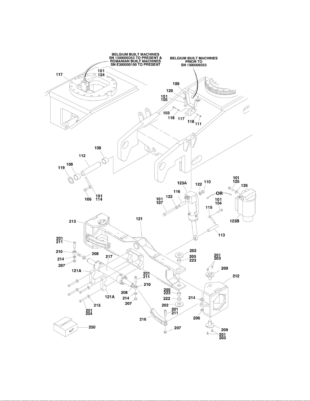
FIGURE 1-1. AXLE AND STEERING INSTALLATION

SECTION 1 - FRAME
3121182 510AJ 11
FIGURE 1-1. AXLE AND STEERING INSTALLATION
ITEM
PART NUMBER
QTY
DESCRIPTION
REV
Ref
OSCILLATING AXLE INSTALLATIONS
0272424
Ref
Belgium Built Machines (Prior to SN 1300000353)
E
0273497
Ref
Belgium Built Machines (SN 1300000353 through 1300003222)
C
0274753
Ref
Belgium Built Machines (SN 1300003223 to Present)
A
0274753
Ref
Romanian Built Machines (SN E300000100 through
E300001114)
A
101
0100011
AR
Compound, Locking
101
0100019
AR
Compound, Locking
102
0100038
AR
Primer, Locking #7471
103
0641416
4
Bolt 1/4in-20NC x 2in (Belgium Built Machines) (Prior to SN
1300000353)
104
0641607
2
Bolt 3/8in-16NC x 3/4in (Belgium Built Machines) (Prior to SN
1300003223)
105
0641810
2
Bolt 1/2in-13NC x 1-1/4in (Belgium Built Machines) (Prior to SN
1300000353)
106
0642012
1
Bolt 5/8in-11NC x 1-1/2in
107
0682248
2
Bolt 3/4in-10NC x 6in (Belgium Built Machines) (Prior to SN
1300003223)
108
0961950
2
Bushing
109
1100134
1
Cam, Lockout (Belgium Built Machines) (Prior to SN
1300000353)
110
3272201
2
Nut 3/4in-10NC (Belgium Built Machines) (Prior to SN
1300003223)
111
3311405
4
Locknut 1/4in-20NC (Belgium Built Machines) (Prior to SN
1300000353)
112
3422592
1
Pin, Axle Pivot
113
3422520
2
Pin (Belgium Built Machines) (Prior to SN 1300003223)
114
3841258
1
Keeper, Pin
115
3841520
2
Keeper, Pin (Belgium Built Machines) (Prior to SN 1300003223)
116
4567462
2
Tube, Mounting (Belgium Built Machines) (Prior to SN
1300003223)
117
Ref
Lockout Valve Assembly Options:
117
4640871
1
Valve used on Belgium Built Machines (Prior to SN
1300000353)
117
7012693
1
Seal Kit - 4640871 Valve
117
7002840
1
Anti-Rotation Pin Removal Tool
117
4641265
1
Valve used on Belgium Built Machines (SN 1300000353 to
Present)
117
4641265
1
Valve used on Romanian Built Machines (SN E300000100
through E300001114)
118
4711400
4
Flatwasher 1/4in Thin (Belgium Built Machines) (Prior to SN
1300000353)
119
4740158
1
Thrustwasher
120
4752000
4
Flatwasher 5/8in Regular (Belgium Built Machines) (Prior to SN
1300000353)
121
Ref
Axle Weldment Options:
Ref
Note: If kingpin holes in the axle measure 1.503in diameter
or larger in any direction, axle weldment must be replaced.
Ref
Note: See Kit Item 250 and additional notes at end of parts
list before ordering parts.
121
4846660
1
Belgium Built Machines (Prior to SN 1300003223)
121
0280203
1
Belgium Built Machines (SN 1300003223 to Present)
121
0280203
1
Romanian Built Machines (SN E300000100 through

SECTION 1 - FRAME
12 510AJ 3121182
ITEM
PART NUMBER
QTY
DESCRIPTION
REV
E300001114)
121A
0561511
2
Steer Cylinder Mounting Block Assembly
122
4892200
4
Flatwasher 3/4in Hardened (Belgium Built Machines) (Prior to
SN 1300003223)
123
Ref
Lockout Cylinder Assembly Options (See CYLINDER SECTION
for Breakdown):
123A
1684243
2
Belgium Built Machines (Prior to SN 1300003223)
123B
1684465
2
Belgium Built Machines (SN 1300003223 to Present)
123B
1684465
2
Romanian Built Machines (SN E300000100 through
E300001114)
124
0791506
4
Screw 5/16in-18NC x 3/4in (Belgium Built Machines) (SN
1300000353 to Present)
125
0641814
8
Bolt 1/2in-13NC x 1-3/4in (Belgium Built Machines) (SN
1300003223 to Present)
126
4891800
8
Flatwasher 1/2in Hardened (Belgium Built Machines) (SN
1300003223 to Present)
126
4891800
8
Flatwasher 1/2in Hardened (Romanian Built Machines) (SN
E300000100 through E300001114)
0272428
Ref
STEERING INSTALLATION
F
201
0100011
AR
Compound, Locking
202
Ref
Thrustwasher Options:
202
0440161
AR
Belgium Built Machines (Top and Bottom Kingpin Location)
(Note: See Kit Item 250 and additional notes at end of parts list
before ordering parts) (Prior to SN 1300000441)
202
4740537
AR
Belgium Built Machines (.0625) (Top Kingpin Location) (SN
1300000441 to Present)
202
4740537
AR
Romanian Built Machines (.0625) (Top Kingpin Location) (SN
E300000100 through E300001114)
202
4740538
AR
Belgium Built Machines (.125) (Top Kingpin Location) (SN
1300000441 to Present)
202
4740538
AR
Romanian Built Machines (.125) (Top Kingpin Location) (SN
E300000100 through E300001114)
202
4740539
AR
Belgium Built Machines (.188) (Top Kingpin Location) (SN
1300000441 to Present)
202
4740539
AR
Romanian Built Machines(.188) (Top Kingpin Location) (SN
E300000100 through E300001114)
202
4740540
AR
Belgium Built Machines (.250) (Top Kingpin Location) (SN
1300000441 to Present)
202
4740540
AR
Romanian Built Machines (.250) (Top Kingpin Location) (SN
E300000100 through E300001114)
202
0440271
AR
Belgium Built Machines (Bottom Kingpin Location) (SN
1300000441 to Present)
202
0440271
AR
Romanian Built Machines (Bottom Kingpin Location) (SN
E300000100 through E300001114)
203
0641606
16
Bolt 3/8in-16NC x 3/4in
204
0641824
4
Bolt 1/2in-13NC x 3in
205
Ref
Bushing / Bearing Options:
205
0961951
2
Belgium Built Machines (Top and Bottom Kingpin Location)
(Note: See Kit Item 250 and additional notes at end of parts list
before ordering parts) (Prior to SN 1300000441)
205
0961951
2
Belgium Built Machines (SN 1300000441 to Present)
205
0961951
2
Romanian Built Machines Options: (SN E300000100 through
E300001114)
205
0440291
2
Bushing / Bearing (Top Kingpin Location)
205
0440274
2
Bushing / Bearing (Bottom Kingpin Location)
206
0962140
2
Bearing, Garmax
SECTION 1 - FRAME
3121182 510AJ 13
ITEM
PART NUMBER
QTY
DESCRIPTION
REV
207
3312008
4
Nut 5/8in-11NC
208
3322201
2
Nut 3/4in-16NC
209
Ref
Kingpin Options:
209
3422716
4
Belgium Built Machines (2 Bolt Mounting) (Note: See Kit Item 250
and additional notes at end of parts (Prior to SN 1300000441)
209
3423081
4
Belgium Built Machines (4 Bolt Mounting) (SN 1300000441 to
Present)
209
3423081
4
Romanian Built Machines (SN E300000100 through
E300001114)
210
Ref
Rod-End with Grease Fitting
210
3841367
2
Belgium Built Machines (Prior to SN 130005313)
210
3841517
2
Belgium Built Machines (SN 130005313 to Present)
210
3841517
2
Romanian Built Machines (SN E300000100 through
E300001114)
211
3900109
4
Screw, Shoulder
212
Ref
Spindle (Left Side) Options:
212
4130391
1
Belgium Built Machines (Prior to SN 1300000441)
212
4130408
1
Belgium Built Machines (SN 1300000441 to Present)
212
4130408
1
Romanian Built Machines (SN E300000100 through
E300001114)
213
Ref
Spindle (Right Side) Options:
213
4130392
1
Belgium Built Machines (Prior to SN 1300000441)
213
4130407
1
Belgium Built Machines (SN 1300000441 to Present)
213
4130407
1
Romanian Built Machines (SN E300000100 through
E300001114)
214
4740086
4
Thrustwasher
215
4751800
4
Flatwasher 1/2in Regular
216
4846666
2
Tie-Rod
217
1684246
1
Steer Cylinder Assembly (See CYLINDER SECTION for
Breakdown)
222
3780182
2
O-Ring (Belgium Built Machines) (SN 1300003223 to Present)
222
3780182
2
O-Ring (Romanian Built Machines) (SN E300000100 through
E300001114)
223
3020029
AR
Grease, Bearing
250
2902400
1
Kingpin & Bushings Update Kit for Belgium Built Machines Built
Prior to SN 1300000441 (Includes Newer “Belgium Built Machines
SN 1300000441 to Present” Design Items 202, 205, 210 & 222).
Refer to Field Service Bulletin AWP-04-11.
Ref
Note: Newer bushings will fit in "Belgium Built Machines Prior
to SN 1300000441" axles however if kingpin holes measure
1.503in diameter or larger in any direction, axle weldment
must be replaced before installation of kit.
Ref
Note: Spindles require drilling and tapping for 8 additional
kingpin mtg bolts. Newer design kingpins require 4 mtg bolts
each.
Ref
Note: All Romanian Built Machines have the newer design
axle.
SECTION 1 - FRAME
14 510AJ 3121182
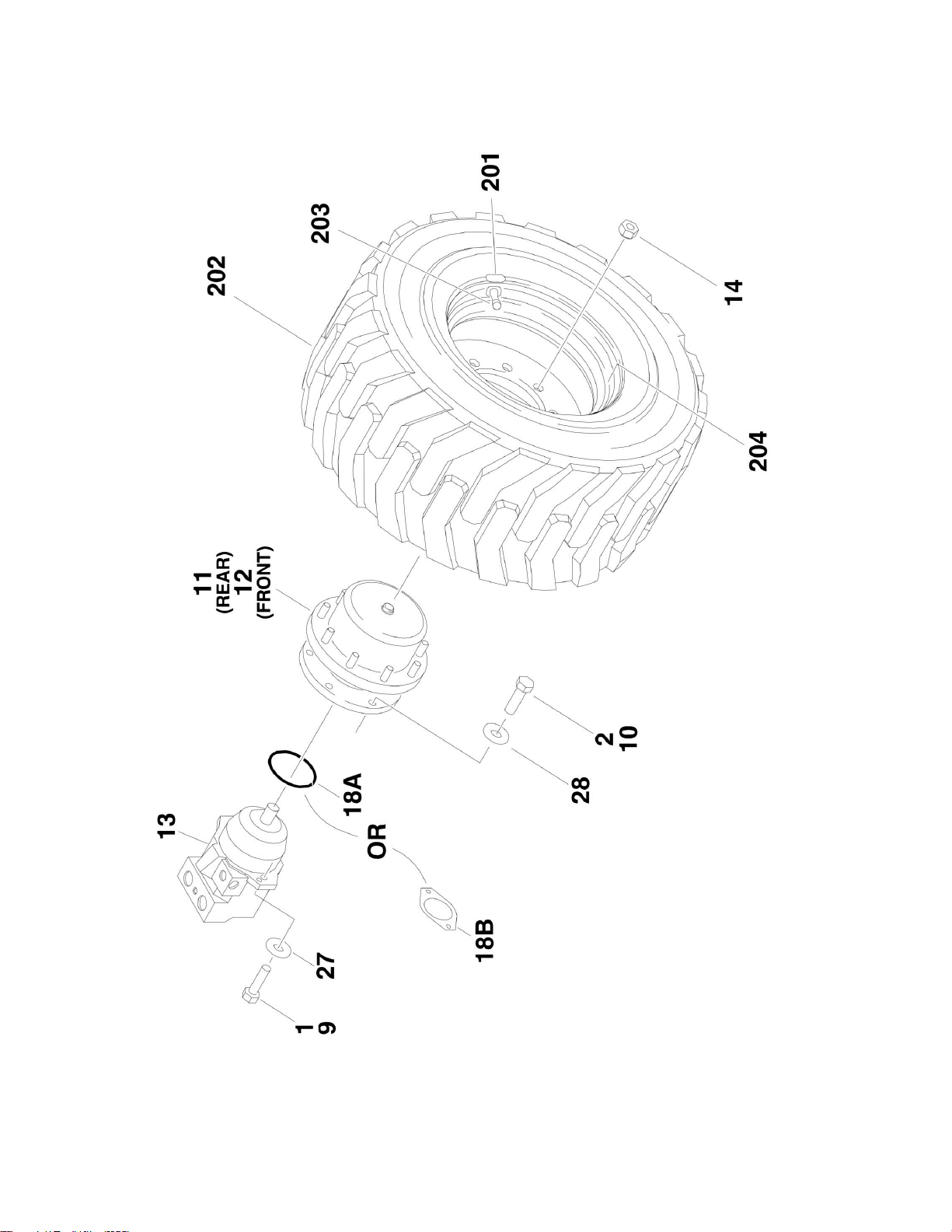
FIGURE 1-2. TIRE AND WHEEL DRIVE INSTALLATIONS

SECTION 1 - FRAME
3121182 510AJ 15
FIGURE 1-2. TIRE AND WHEEL DRIVE INSTALLATIONS
ITEM
PART NUMBER
QTY
DESCRIPTION
REV
Ref
WHEEL DRIVE INSTALLATIONS
0272320
Ref
Wheel Drive Installations (Prior to SN 1300000159)
C
0272895
Ref
Wheel Drive Installations (SN 1300000159 through
1300003222)
G
0275854
Ref
Wheel Drive Installations (SN 1300003223 through
E300001114)
C
1
0100011
AR
Compound, Locking
2
0100019
AR
Compound, Locking
9
Ref
Hardware Options:
9
0681810
8
Bolt 1/2in-13NC x 1-1/4in (Grade 8) (Both Front and Rear Axle)
(Belgium Built Machines) (Prior to SN 1300000162)
9
0681810
4
Bolt 1/2in-13NC x 1-1/4in (Grade 8) (Front Axle) (Belgium Built
Machines) (SN 1300000162 to Present)
9
0681810
4
Bolt 1/2in-13NC x 1-1/4in (Grade 8) (Front Axle) (Romanian
Built Machines) (SN E300000100 through E300001114)
9
3311801
4
Nut 1/2in-13NC (Not Shown) (Rear Axle) (Belgium Built
Machines) (SN 1300000162 to Present)
9
3311801
4
Nut 1/2in-13NC (Not Shown) (Rear Axle) (Romanian Built
Machines) (SN E300000100 through E300001114)
10
0682014
24
Bolt 5/8in-11NC x 1-3/4in (Grade 8)
11
Ref
Drive Hub/Brake Assembly (Rear) Options:
11
2780256
2
Belgium Built Machines (See DRIVE HUB/BRAKE ASSEMBLY
(REAR) for Breakdown) (Prior to SN 1300000159)
11
2780267
2
Belgium Built Machines (See DRIVE HUB/BRAKE ASSEMBLY
(REAR) for Breakdown) (SN 1300000159 to Present)
11
2780267
2
Romanian Built Machines (See DRIVE HUB/BRAKE
ASSEMBLY (REAR) for Breakdown) (SN E300000100 through
E300001114)
12
Ref
Drive Hub Assembly (Front) Options:
12
2780257
2
Belgium Built Machines (See DRIVE HUB ASSEMBLY
(FRONT) for Breakdown) (Prior to SN 1300000159)
12
2780268
2
Belgium Built Machines (See DRIVE HUB ASSEMBLY
(FRONT) for Breakdown) (SN 1300000159 to Present)
12
2780268
2
Romanian Built Machines (See DRIVE HUB ASSEMBLY
(FRONT) for Breakdown) (SN E300000100 through
E300001114)
13
Ref
Drive Motor Assembly Options:
13
3160266
4
Belgium Built Machines (Use p/n 3160348 - See DRIVE
MOTOR ASSEMBLY for Breakdown) (For 3160348 Motor - See
DRIVE MOTOR ASSEMBLY for Breakdown) (Prior to SN
1300002249)
13
3160348
4
Belgium Built Machines (See DRIVE MOTOR ASSEMBLY for
Breakdown) (SN 1300002249 to Present)
13
3160348
4
Romanian Built Machines (See DRIVE MOTOR ASSEMBLY for
Breakdown) (SN E300000100 through E300001114)
14
3300106
36
Lugnut
18
Ref
Seal Options:
18A
3790045
2
O-Ring Belgium Built Machines (Prior to SN 1300002638)
18B
3960526
4
Gasket Belgium Built Machines (SN 1300002638 to Present)
18B
3960526
4
Gasket Romanian Built Machines (SN E300000100 through
E300001114)
27
4891800
8
Flatwasher 1/2in Hardened
28
4892000
24
Flatwasher 5/8in Hardened
31
2300016
AR
Fluid, Hydraulic (Not Shown)
SECTION 1 - FRAME
16 510AJ 3121182
ITEM
PART NUMBER
QTY
DESCRIPTION
REV
32
3020008
AR
Lubricant, Mobilube HD 80W - 90 (Not Shown)
Ref
TIRE AND WHEEL INSTALLATION OPTIONS
0258028
Ref
12 x 16.5 Pneumatic (ANSI/ANSI Export/CSA/Japanese Specs
Only. Not Available on CE/Australian Specs)
A
0258030
Ref
12 x 16.5 Foam-Filled (Available on all Specs)
A
0270674
Ref
12 x 16.5 Foam-Filled, Non-Marking (Available on all Specs)
B
0258031
Ref
33/1550 x 16.5 Foam-Filled
B
0258831
Ref
33/16LL x 16.1 Pneumatic (ANSI/ANSI Export/CSA/Japanese
Specs Only. Not Available on CE/Australian Specs) (Requires
special counterweighting)
A
0257740
2
12 x 16.5 Pneumatic Right Side (Not Available on CE/Australian
Specs)
C
0257746
2
12 x 16.5 Pneumatic Left Side (Not Available on CE/Australian
Specs)
C
0258009
2
12 x 16.5 Foam-Filled Right Side
C
0258010
2
12 x 16.5 Foam-Filled Left Side
C
0270675
2
12 x 16.5 Foam-Filled Non-Marking Right Side
A
0270676
2
12 x 16.5 Foam-Filled Non-Marking Left Side
A
0258011
2
33/1550 x 16.5 Foam-Filled Right Side
D
0258012
2
33/1550 x 16.5 Foam-Filled Left Side
D
0258830
4
33/16LL x 16.1 Pneumatic (Not Available on CE/Australian
Specs) (Requires special counterweighting)
Ref
Note: Assemblies may require ballast/foam filling to
manufacture's specifications prior to installing on a
machine. Refer to Operation and Safety or Service and
Maintenance Manuals. Purchase individual tire and/or rim
only if able to foam fill tire and wheel assembly, otherwise,
purchase complete assembly.
201
Ref
Decal Options (Pneumatic Only):
201
1702740
1
Decal - 90PSI
201
1703067
1
Decal - 40PSI
202
Ref
Tire Options:
202
4520216
1
12 x 16.5 NHS (OTR Brand)
202
4520240
1
12 x 16.5 Non-Marking (OTR Brand)
202
4520217
1
33/1550 x 16.5 NHS (OTR Brand)
202
4520212
1
33/16LL x 16.1 (Galaxy Brand)
203
Ref
Valve Stem Options:, Air (Pneumatic Only)
203
4640113
1
All except 33/1550 x 16.5 Foam-Filled Tire and Wheel Assy
203
8786514
1
33/1550 x 16.5 Foam-Filled Tire and Wheel Assy Only
204
Ref
Rim, Wheel Options:
204
4860178
1
16.5 x 12 (Use with 12 x 16.5 Tires)
204
4860179
1
16.5 x 12 (Use with 33/1550 x 16.5 Tires)
204
4860193
1
16.1 x 14 (Use with 33/16LL x 16.1 Tires)


SECTION 1 - FRAME
18 510AJ 3121182
FIGURE 1-3. DRIVE HUB/BRAKE ASSEMBLY (REAR)

SECTION 1 - FRAME
3121182 510AJ 19
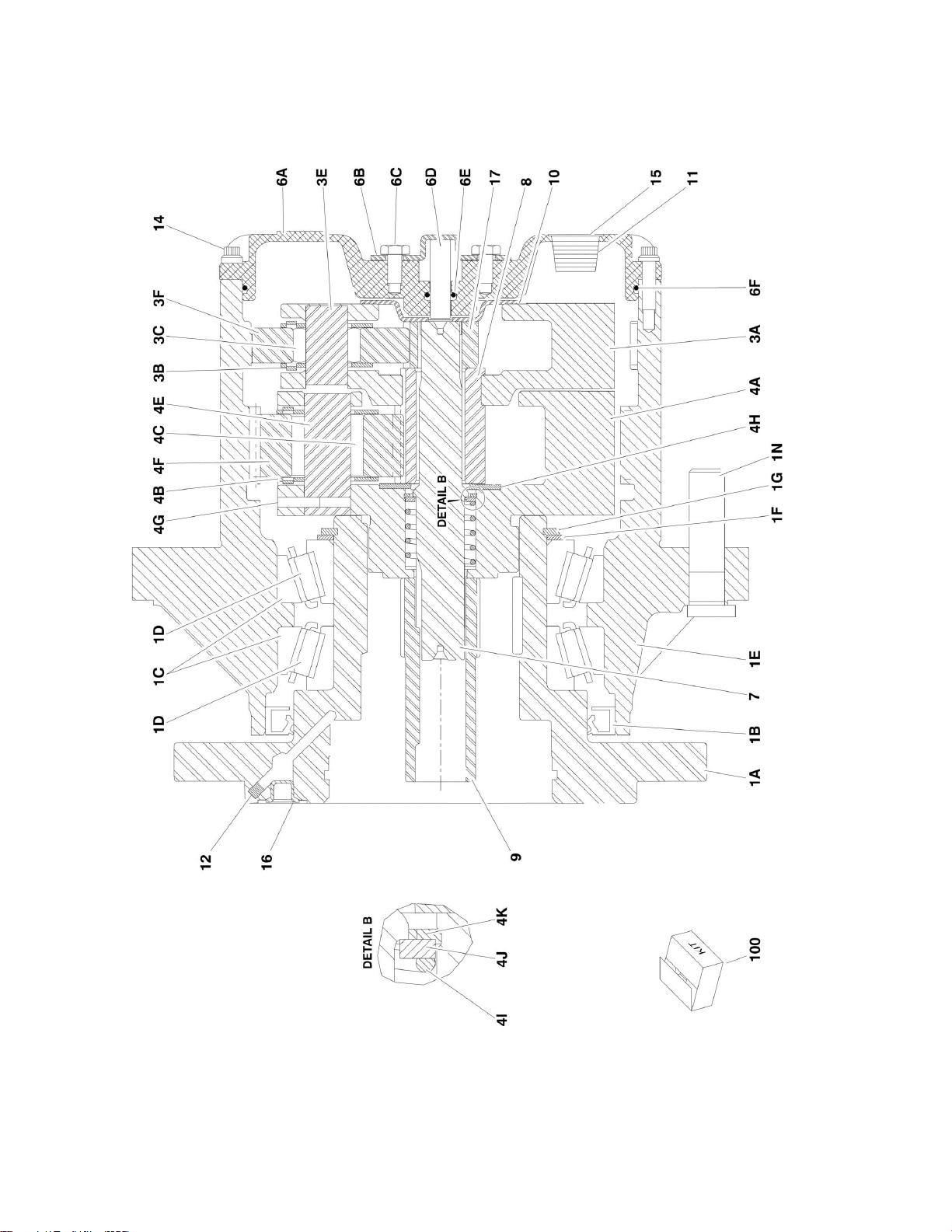
FIGURE 1-3. DRIVE HUB/BRAKE ASSEMBLY (REAR)
ITEM
PART NUMBER
QTY
DESCRIPTION
REV
Ref
USAGE: USED BELGIUM BUILT MACHINES (Prior to SN
1300000159)
Ref
NOTE: Hub may have been replaced with Service Kit p/n
1001178138. Kit uses hub p/n 2780267. See next figure for
service parts.
2780256
Ref
DRIVE HUB/BRAKE ASSEMBLY
G
1
See Note
1
Spindle/Housing Assembly (Note: Not Available - Purchase
Individual Components)
1A
7024105
1
Spindle
1B
7024113
1
Seal
1C
7007006
2
Cone, Bearing
1D
7024112
2
Cup, Bearing
1E
7024110
1
Housing/Ring Gear
1F
7024109
1
Thrustwasher
1G
7024107
1
Ring, Retaining
1N
7024111
9
Stud, Wheel
2
7024106
1
Brake, Input
2A
7024710
1
Kit, Brake Lining (Includes Qty 8 Outer Plates and Qty 7 Inner
Plates)
2B
7024709
1
Kit, Brake O-Ring (Includes Qty 2 O-Rings and Back-up Rings)
2C
7024711
1
Kit, Brake Spring (Includes Qty 12 Springs)
2D
7024719
1
Kit, Brake Hardware (Includes End Plate, Spacer and Qty 2 E-
Clips)
3
See Note
1
Carrier Assembly (Note: Not Available - Purchase Individual
Components)
3A
7024116
1
Carrier
3B
7024127
6
Thrustwasher
3C
7024123
42
Bearing, Needle
3E
7024120
3
Shaft, Planet
3F
7024118
3
Gear, Planet
4
See Note
1
Carrier Assembly (Note: Not Available - Purchase Individual
Components)
4A
7024117
1
Carrier
4B
7024126
6
Thrustwasher
4C
7024122
45
Bearing, Needle
4E
7024121
3
Shaft, Planet
4F
7024119
3
Gear, Planet
4G
7001913
3
Rollpin
4H
7024128
1
Thrustwasher
4I
7024124
1
Spring
4J
7024129
1
Thrustwasher
4K
7024125
1
Thrustwasher
6
See Note
1
Cover Assembly (Note: Not Available - Purchase Individual
Components)
6A
7024132
1
Plate, Cover
6B
7017093
1
Cap, Disengage
6C
0641404
2
Bolt 1/2in-20NC x 1/2in
6D
7017092
1
Pin, Dowel
6E
7017095
1
O-Ring
6F
7024134
1
O-Ring
7
7024130
1
Shaft, Input
8
7024115
1
Gear, Sun
SECTION 1 - FRAME
20 510AJ 3121182
ITEM
PART NUMBER
QTY
DESCRIPTION
REV
9
7024131
1
Coupling
10
7017097
1
Spacer, Thrust
11
7017094
2
Plug, Pipe
12
7024108
1
Plug, Pressure
14
7024133
12
Bolt 1/4in-20NC x 7/8in (Grade 8)
15
See Note
1
Plate, ID (Not Shown) (Note: Not Available for Purchase)
16
7017082
1
Plug, O-Ring
17
7024114
1
Gear, Sun
100
7024198
1
Seal Kit (Includes Items 1B, 1G & 6F)


SECTION 1 - FRAME
22 510AJ 3121182
FIGURE 1-4. DRIVE HUB/BRAKE ASSEMBLY (REAR)

SECTION 1 - FRAME
3121182 510AJ 23
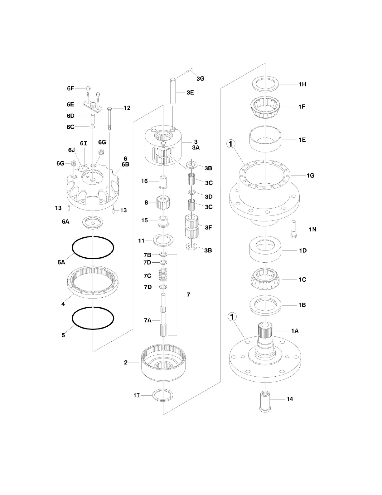
FIGURE 1-4. DRIVE HUB/BRAKE ASSEMBLY (REAR)
ITEM
PART NUMBER
QTY
DESCRIPTION
REV
Ref
USAGE: USED BELGIUM BUILT MACHINES (SN 1300000159 to
Present)
Ref
USAGE: USED ROMANIAN BUILT MACHINES (SN E300000100
through E300001114)
2780267
Ref
DRIVE HUB/BRAKE ASSEMBLY
D
1
See Note
1
Spindle/Housing Assembly (Note: Not Available - Purchase
Individual Components)
1A
7017059
1
Spindle
1B
7001998
1
Seal
1C
7010429
1
Cone, Bearing (Includes Item 1D)
1D
7010429
1
Cup, Bearing (Includes Item 1C)
1E
7000257
1
Cup, Bearing
1F
7000258
1
Cone, Bearing
1G
7007601
1
Housing/Ring Gear
1H
7000232
1
Thrustwasher
1I
7000229
1
Ring, Retaining
1N
7007640
9
Stud, Wheel
2
7000246
1
Gear, Internal
3
7024712
1
Carrier Assembly
3A
7024712
1
Carrier
3B
7024712
6
Ring, Retaining
3C
7024712
AR
Bearing, Needle
3D
7024712
3
Thrustwasher
3E
7024712
3
Shaft, Planet
3F
7024712
3
Gear, Planet
3G
7024712
3
Rollpin
4
7000248
1
Ring Gear
5
7000230
1
O-Ring
5A
7017070
1
O-Ring
6
70001349
1
Cover Assembly (was p/n 7017090)
6A
70001349
1
Spacer, Thrust (was p/n 7017097)
6B
70001349
1
Plate, Cover (was p/n 7017091)
6C
70001349
1
O-Ring (was p/n 7017095)
6D
70001349
1
Rod, Disconnect (was p/n 7017092)
6E
70001349
1
Cap, Disengage (was p/n 7017093)
6F
70001349
2
Bolt (was p/n 0641404)
6G
7017094
1
Plug, Pipe
6I
See Note
4
Rivet (Note: Not Available - Purchase Locally)
6J
See Note
1
Plate, ID (Note: Not Available for Purchase)
7
Ref
Input Shaft Assembly
7A
7024714
1
Shaft
7B
7000261
1
Ring, Retaining
7C
7000262
1
Spring
7D
7000263
2
Spacer, Thrust
8
7024713
1
Gear, Sun
11
7000253
1
Thrustwasher
12
7017067
12
Bolt
13
7017080
4
Pin, Dowell
14
7000206
1
Coupling
15
7024715
1
Spacer, Input

SECTION 1 - FRAME
24 510AJ 3121182
ITEM
PART NUMBER
QTY
DESCRIPTION
REV
16
7024716
1
Spacer, Input
17
7024182
1
Brake Assembly (See Items 101-123 for Breakdown)
27
7024705
1
O-Ring
28
7024717
2
Rod, Threaded
29
7024718
2
Nut 1/2in-13NC
30
7000731
1
Gasket
7024182
Ref
BRAKE ASSEMBLY
101
7024189
1
Shaft
102
7024182
1
Housing
103
I7024193
2
Plate, Friction
104
7024193
1
Plate, Pressure
105
7000731
1
Gasket
106
7024193
2
Plate, Outer
107
See Note
1
Gasket (Note: Use Item 150, 153 or 154.)
108
7024191
1
Cylinder
109
7024192
1
Piston
110
7024197
1
Bearing, Ball
111
7024197
1
Ring, Retaining
112
7024197
1
Seal, Shaft
113
See Note
6
Capscrew (Note: Not Available - Purchase Locally)
114
See Note
6
Lockwasher (Note: Not Available - Purchase Locally)
115
7024194
1
O-Ring
116
7024194
1
Ring, Back-up
117
7024194
1
O-Ring
118
7024194
1
Ring, Back-up
119
7024190
2
Pin, Dowel
120
See Note
1
Plug (Note: Not Available - Purchase Locally)
121
See Note
2
Plug (Note: Not Available - Purchase Locally)
122
7024196
10
Spring Kit (Natural)
123
7024196
2
Spring Kit (Blue)
150
7024194
1
Seal Kit, Brake (Includes Items 105, 107 & 115-118)
151
7024196
1
Spring Kit, Brake (Includes 12 Natural Colored Springs Item 122)
(was p/n 7024195)
152
7024196
1
Spring Kit, Brake (Includes 12 Natural Colored Springs Item 122 &
2 Blue Springs Colored Springs Item 123)
153
7024193
1
Friction Disc Kit, Brake (Includes Items 103, 104, 106 & 107)
154
7024197
1
Bearing Kit, Brake (Includes Items 107 & 110-112)

SECTION 1 - FRAME
26 510AJ 3121182
FIGURE 1-5. DRIVE HUB ASSEMBLY (FRONT)

SECTION 1 - FRAME
3121182 510AJ 27
FIGURE 1-5. DRIVE HUB ASSEMBLY (FRONT)
ITEM
PART NUMBER
QTY
DESCRIPTION
REV
Ref
USAGE: BELGIUM BUILT MACHINES USED (Prior to SN
1300000064)
Ref
NOTE: Hub may have been replaced with Service Kit p/n
1001178136. Kit uses hub p/n 2780268. See next figure for
service parts.
2780257
Ref
DRIVE HUB ASSEMBLY
F
1
See Note
1
Spindle/Housing Assembly (Note: Not Available - Purchase
Individual Components)
1A
7024105
1
Spindle
1B
7024113
1
Seal
1C
7007006
2
Cone, Bearing
1D
7024112
2
Cup, Bearing
1E
7024110
1
Housing/Ring Gear
1F
7024109
1
Thrustwasher
1G
7024107
1
Ring, Retaining
1N
7024111
9
Stud, Wheel
3
See Note
1
Carrier Assembly (Note: Not Available - Purchase Individual
Components)
3A
7024116
1
Carrier
3B
7024127
6
Thrustwasher
3C
7024123
42
Bearing, Needle
3E
7024120
3
Shaft, Planet
3F
7024118
3
Gear, Planet
4
See Note
1
Carrier Assembly (Note: Not Available - Purchase Individual
Components)
4A
7024117
1
Carrier
4B
7024126
6
Thrustwasher
4C
7024122
45
Bearing, Needle
4E
7024121
3
Shaft, Planet
4F
7024119
3
Gear, Planet
4G
7001913
3
Rollpin
4H
7024128
1
Thrustwasher
4I
7024124
1
Spring
4J
7024129
1
Thrustwasher
4K
7024125
1
Thrustwasher
6
See Note
1
Cover Assembly (Note: Not Available - Purchase Individual
Components)
6A
7024132
1
Plate, Cover
6B
7017093
1
Cap, Disengage
6C
0641404
2
Bolt 1/2in-20NC x 1/2in
6D
7017092
1
Pin, Dowel
6E
7017095
1
O-Ring
6F
7024134
1
O-Ring
7
7024130
1
Shaft, Input
8
7024115
1
Gear, Sun
9
7024131
1
Coupling
10
7017097
1
Spacer, Thrust
11
7017094
2
Plug, Pipe
12
7024108
1
Plug, Pressure
14
7024133
12
Bolt 1/4in-20NC x 7/8in (Grade 8)
15
See Note
1
Plate, ID (Not Shown) (Note: Not Available For Purchase)

SECTION 1 - FRAME
28 510AJ 3121182
ITEM
PART NUMBER
QTY
DESCRIPTION
REV
16
7017082
1
Plug, O-Ring
17
7024114
1
Gear, Sun
100
7024198
1
Seal Kit (Includes Items 1B, 1G & 6F)

SECTION 1 - FRAME
30 510AJ 3121182
FIGURE 1-6. DRIVE HUB ASSEMBLY (FRONT)
Loading...