


Operation & Safety
An Oshkosh Corporation Company
Manual
Original Instructions
Keep this manual with machine at all times.
Telehandler
Personnel Work
Platform
31200160
Revised
June 15, 2012

CALIFORNIA PROPOSITION 65
BATTERY WARNING
Battery posts,
terminals and related
accessories contain
lead and lead compounds,
chemical known to the
State of California
to cause cancer and
reproductive harm.
WASH HANDS
AFTER HANDLING!
CALIFORNIA PROPOSITION 65
EXHAUST WARNING
Diesel Engine exhaust and
some of its constituents
are known to the State of
California to cause cancer,
birth defects and other
reproductive harm.

Revision Log
Revision Log
January 2, 2007 - A - Original Issue of Manual
March 22, 2007 - B - Revised pages 3-1, 4-4 and 6-1.
February 14, 2008 - C - Revised pages 1-1, 1-2, 2-1, 2-4, 4-2, 4-3 and 4-4.
December 10, 2008 - D - Revised covers and pages c & 5-1.
June 15, 2012 - E - Revised covers and pages 1-5, 1-11, 2-1, 2-4, 3-4, 4-2 & 5-1.
REVISION LOG
a31200160

Read This First
Read This First
This manual is a very important tool! Keep it with the machine at all times.
The purpose of this manual is to provide owners, users, operators, lessors, and
lessees with the precautions and operating procedures essential for the safe and
proper machine operation for its intended purpose.
Due to continuous product improvements, JLG Industries, Inc. reserves the right to
make specification changes without prior notification. Contact JLG Industries, Inc.
for updated information.
Telehandler Operator and Platform Occupant Qualifications
The telehandler operator and platform occupants must read and understand this
manual.
The telehandler operator must read and understand the telehandler Operation &
Safety Manual and any optional equipment instructions prior to operation.
The operator must also read, understand and comply with all applicable Employer,
Industry and Governmental rules, standards and regulations.
Modifications
Any modification to the platform must be approved by the platform
manufacturer.
b 31200160

Read This First
This product must comply with all safety related bulletins. Contact JLG Industries,
Inc. or the local authorized JLG representative for information regarding safetyrelated bulletins which may have been issued for this product.
JLG Industries, Inc. sends safety related bulletins to the owner of record of this
machine. Contact JLG Industries, Inc. to ensure that the current owner records are
updated and accurate.
JLG Industries, Inc. must be notified immediately in all instances where JLG
products have been involved in an accident involving bodily injury or death of
personnel or when damage has occurred to personal property or the JLG product.
FOR:
• Accident Reporting and Product Safety Publications
• Current Owner Updates
• Questions Regarding Product Applications and Safety
• Standards and Regulations Compliance Information
• Questions Regarding Product Modifications
CONTACT:
Product Safety and Reliability Department
JLG Industries, Inc.
13224 Fountainhead Plaza
Hagerstown, MD 21742
USA
or Your Local JLG Office
(Addresses on back cover)
In USA:
Toll Free: 1-877-JLG-SAFE (1-877-554-7233)
Outside USA:
Phone: +1-717-485-6591
E-mail: ProductSafety@JLG.com
c31200160

Read This First
This Page Intentionally Left Blank
d 31200160

Table of Contents
TABLE OF CONTENTS
Revision Log
Read This First
Telehandler Operator and Platform
Occupant Qualifications ..................................................... b
Modifications ...................................................................... b
Table of Contents
Section 1 - General Safety Practices
1.1 Hazard Classification System ..............................................1-1
Safety Alert System and Safety Signal Words................1-1
1.2 General Precautions ............................................................1-2
1.3 Operation Safety ..................................................................1-3
Electrical Hazards ...........................................................1-3
Tip Over Hazard..............................................................1-4
Load Falling Hazard ........................................................1-6
Pinch Points and Crush Hazards ....................................1-7
Fall Hazard......................................................................1-9
Chemical Hazards.........................................................1-11
Section 2 - Pre-Operation and Inspection
2.1 Pre-Operation Check and Inspection...................................2-1
2.2 Safety Decals - JLG Supplied Personnel Work Platform.....2-2
Quick Switch Mounted .................................................... 2-2
Fork Mounted..................................................................2-4
2.3 Walk-Around Inspection.......................................................2-5
2.4 Warm-Up and Operational Checks ......................................2-6
Warm-Up Check ............................................................. 2-6
Operational Check .......................................................... 2-6
Table of Contents
Section 3 - Operation
3.1 Platform Operation...............................................................3-1
Lifting/Lowering Personnel..............................................3-1
3.2 Use of the Capacity Chart ....................................................3-2
Example ..........................................................................3-2
3.3 Loading and Securing for Transport .................................... 3-4
i31200160

Table of Contents
Section 4 - Types of Personnel Work Platforms
4.1 Approved Personnel Work Platforms .................................. 4-1
Quick Switch Mounted - JLG Supplied ........................... 4-1
Fork Mounted ................................................................. 4-1
4.2 Unapproved Personnel Work Platforms .............................. 4-2
4.3 Platform Installation ............................................................. 4-3
Quick Switch Mounted - JLG Supplied ........................... 4-3
Fork Mounted ................................................................. 4-4
Section 5 - Emergency Procedures
5.1 Emergency Lowering of Boom ............................................ 5-1
5.2 Incident Notification ............................................................. 5-1
Section 6 - Specifications
6.1 Product Specifications - JLG Supplied Personnel
Work Platform...................................................................... 6-1
Performance ................................................................... 6-1
Dimensions of Platform .................................................. 6-1
Index
Inspection, Maintenance and Repair Log
ii 31200160

Section 1 - General Safety Practices
DANGER
OW0010
WARNING
OW0021
CAUTION
OW0031
SECTION 1 - GENERAL SAFETY PRACTICES
1.1 HAZARD CLASSIFICATION SYSTEM
Safety Alert System and Safety Signal Words
DANGER indicates an imminently hazardous situation which, if not avoided, will
result in death or serious injury.
WARNIN G indicates a potentially hazardous situation which, if not avoided, could
result in death or serious injury.
CAUTION indicates a potentiality hazardous situation which, if not avoided, may
result in minor or moderate injury.
1-131200160
Section 1 - General Safety Practices
OAB0050
1.2 GENERAL PRECAUTIONS
WARNING
Before operation, read & understand this manual. Failure to comply with the
safety precautions listed in this manual could result in machine damage, property
damage, personal injury or death.
• DO NOT use the telehandler with platform attached for any purpose other than
positioning personnel, their tools and equipment.
• DO NOT place boom or platform against any structure to steady the platform or
to support the structure.
• Operator must remain in cab and keep platform occupants in direct line of sight.
• Prior to lifting personnel, platform occupants and telehandler operator must
establish means of communication.
1-2 31200160

1.3 OPERATION SAFETY
OAB0010
Electrical Hazards
• This machine is not insulated and does not provide protection from contact or
proximity to electrical current.
Voltage Range
(Phase to Phase)
0 to 50 KV 10 ft (3 m)
Over 50 KV to 200 KV 15 ft (5 m)
Over 200 KV to 350 KV 20 ft (6 m)
Over 350 KV to 500 KV 25 ft (8 m)
Over 500 KV to 750 KV 35 ft (11 m)
Over 750 KV to 1000 KV 45 ft (14 m)
Note: This requirement shall apply except where employer, local or
governmental regulations are more stringent.
• Maintain safe distance from electrical lines, apparatus or any energized
(exposed or insulated) parts according to the Minimum Safe Approach Distance
(MSAD).
• Allow for machine movement and electrical line swaying.
• Maintain a clearance of at least 10 ft (3 m) between any part of the machine and
its occupants, their tools and equipment from any electrical line or apparatus
carrying up to 50,000 volts. One foot additional clearance is required for every
additional 30,000 volts or less.
• The minimum safe approach distance may be reduced if insulating barriers are
installed to prevent contact and the barriers are rated for the voltage of the line
being guarded. These barriers shall not be part of (or attached to) the machine.
The minimum safe approach distance shall be reduced to a distance within the
designed working dimensions of the insulating barrier. This determination shall
be made by a qualified person in accordance with the employer, local or
governmental requirements for work practices near energized equipment.
MINIMUM SAFE APPROACH
DISTANCE (MSAD)
1-331200160
Section 1 - General Safety Practices
OAB0020
OAB0030
OAB0040
OH2291
Tip Over Hazard
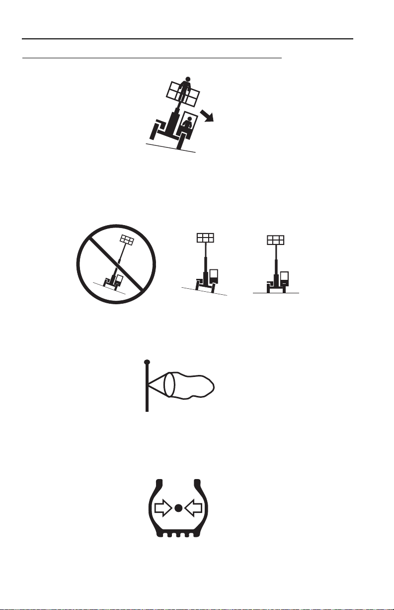
• DO NOT exceed rated lift capacity. Distribute loads evenly on platform floor.
• Be sure that the ground conditions are able to support the machine.
• DO NOT raise boom unless frame is level (0 degrees).
• DO NOT lift personnel during thunderstorms, strong winds or other inclement
weather.
• MAINTAIN proper tire pressure at all times. If proper tire pressures are not
maintained, this machine could tip over.
1-4 31200160
Section 1 - General Safety Practices
OW0170
OW01
90
OAB0070
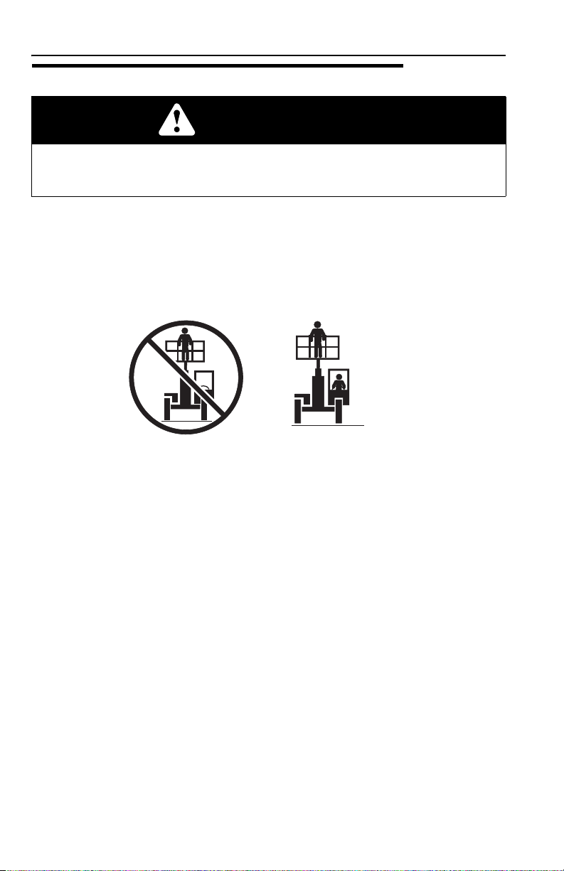
• USE ONLY an approved personnel work platform.
• DO NOT drive machine from cab when personnel are in platform.
• Never level the machine when the platform is occupied.
1-531200160

Section 1 - General Safety Practices
OZ1350
Load Falling Hazard
• Never suspend load from platform or supports.
• DO NOT carry materials directly on platform railing unless approved by the
platform manufacturer.
• Always ensure that power tools are properly stowed and never left hanging by
their cord from the platform work area.
1-6 31200160

Section 1 - General Safety Practices
OW0210
OW0220
OW0230
OW0240
Pinch Points and Crush Hazards
Stay clear of pinch points and rotating parts on the telehandler.
• Stay clear of moving parts while engine is running.
• Keep clear of tires and platform or other objects.
• Keep clear from under boom.
• Keep clear of boom holes.
1-731200160

Section 1 - General Safety Practices
OW0250
O
AB0170
O
AB0060
OZ1310
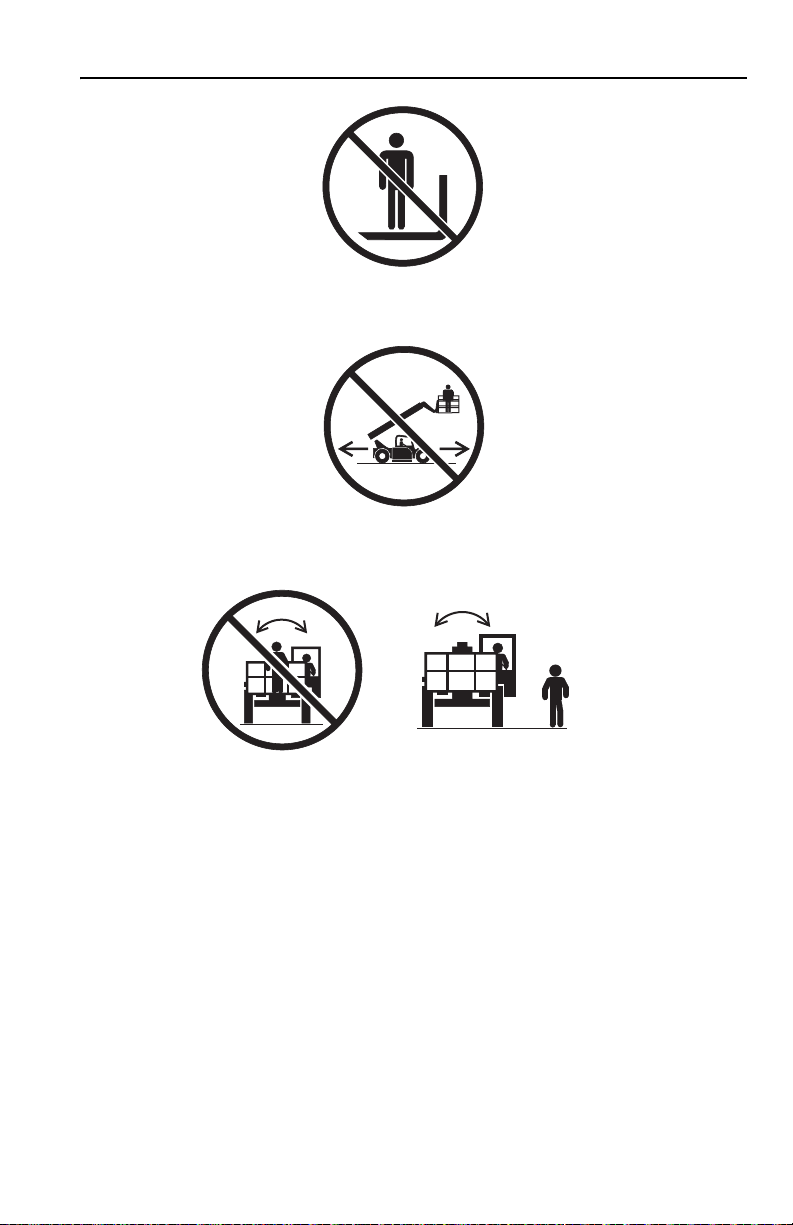
• Keep arms and hands clear of attachment tilt cylinder.
• During operation, keep all body parts inside platform railing.
• Keep others away while operating.
• Approved head gear must be worn by all platform personnel.
• Check work area for clearances overhead, on sides and bottom of platform when
lifting or lowering platform. Always look in direction of movement.
• Be sure that operators of other overhead and floor level machines are aware of
the machine’s presence. Disconnect power to overhead cranes.
1-8 31200160

Section 1 - General Safety Practices
OZ1290
OZ1300
Fall Hazard
• During operation, occupants in the platform must wear a full body harness with a
lanyard attached to an authorized lanyard anchorage point. Attach only one
lanyard per lanyard anchorage point.
• DO NOT use damaged harnesses, deceleration devices or lanyards.
• Before operating the machine, make sure all gates are closed and fastened in
their proper position.
• Keep both feet firmly positioned on the platform floor at all times. Never use
ladders, boxes, steps, planks or similar items on platform to provide additional
reach.
• Use hand rails, if equipped, to maintain balance while platform is in motion.
• Never use the boom assembly to enter or leave the platform.
• Use extreme caution when entering or leaving platform. Be sure that the boom is
fully lowered. Face the machine, maintain three point contact with the machine,
using two hands and one foot or two feet and one hand during entry and exit.
• Platform-to-structure transfers at elevated positions are discouraged. Where
transfer is necessary, enter/exit through the gate only with the platform within 1 ft
(0,3 m) of a safe and secure structure. 100% tie-off is also required in this
situation utilizing two lanyards. One lanyard must be attached to the platform
with the second lanyard attached to the structure. The lanyard connected to the
platform must not be disconnected until such time as the transfer to the structure
is safe and complete.
• Avoid accumulation of debris on platform floor. Keep mud, oil, grease and other
slippery substances from footwear and platform deck.
1-931200160

Section 1 - General Safety Practices
OAB0160
• Never tilt the platform when the platform is occupied.
1-10 31200160

Section 1 - General Safety Practices
OW0300
OW0950
Chemical Hazards
Exhaust Fumes
• DO NOT operate machine in an enclosed area without proper ventilation.
• DO NOT operate the machine in hazardous environments unless approved for
that purpose by JLG and site owner. Sparks from the electrical system and the
engine exhaust can cause an explosion.
Flammable Fuel
• DO NOT fill the fuel tank or service the fuel system near an open flame, sparks
or smoking materials. Engine fuel is flammable and can cause a fire and/or
explosion.
Hydraulic Fluid
• DO NOT attempt to repair or tighten any hydraulic hoses or fittings while the
engine is running or when the hydraulic system is under pressure.
• Stop engine and relieve trapped pressure. Fluid in the hydraulic system is under
enough pressure that it can penetrate the skin.
• DO NOT use your hand to check for leaks. Use a piece of cardboard or paper to
search for leaks. Wear gloves to protect hands from spraying fluid.
Welding
• DO NOT use machine as a ground for welding.
• When performing welding or metal cutting operations, precautions must be taken
to protect the chassis from direct exposure to weld and metal cutting spatter.
1-1131200160

Section 1 - General Safety Practices
This Page Intentionally Left Blank
1-12 31200160

Section 2 - Pre-Operation and Inspection
SECTION 2 - PRE-OPERATION AND INSPECTION
2.1 PRE-OPERATION CHECK AND INSPECTION
Note: Complete all required maintenance before operating unit.
WARNING
FALL HAZARD. Use extreme caution when checking items beyond your normal
reach. Use an approved ladder.
A pre-operation check & inspection of the telehandler is to be completed first. Refer
to the Operation & Safety Manual supplied with telehandler.
The pre-operation check & inspection, performed at beginning of each work shift or
at each change of operator, should include the following:
1. Cleanliness - Check all surfaces for foreign objects.
2. Structure - Inspect the platform structure for dents, damage, weld or parent
metal cracks or other discrepancies.
3. Safety Decals - Ensure all safety decals are legible and in place. Clean or
replace as required. See page 2-2 for details.
4. Operation & Safety Manual - Operation & Safety manual located in platform
manual holder.
5. Walk-Around Inspection - See page 2-5 for details.
6. Operational Check - Once the walk-around inspection is complete, perform a
warm-up and operational check (see page 2-6) in an area free of overhead and
ground level obstructions.
WARNING
If the telehandler does not operate properly, immediately bring machine to a stop,
lower boom and platform to ground and stop engine. Determine cause and
correct before continued use.
2-131200160

Section 2 - Pre-Operation and Inspection
OAB0120
1704277 B
1704277
90553032
ATTACH LANYARD HERE
9055-3032
90553026
90553031
90553033
406 MILL AVE. S.W. NEW PHILADELPHIA, OHIO MADE IN U. S. A.
DO NOT USE PERSONNEL WORK PLATFORM WITHOUT THE
PROPER GRADALL MATERIAL HANDLER/PERSONNEL WORK
PLATFORM CAPACITY CHART DISPLAYED IN CAB.
9055-3033
ATTACHMENT
SERIAL NUMBER
WEIGHT
CAPACITY
HYD. PRESSURE
9055-3026 REV. A
READ AND UNDERSTAND THE FOLLOWING PRIOR TO LIFTING PERSONNEL.
WHEN LIFTING PERSONNEL USE ONLY A GRADALL MANUFACTURED
PERSONNEL WORK PLATFORM.
ALL PERSONNEL IN PLATFORM MUST WEAR A FULL BODY HARNESS WITH
LANYARD ATTACHED TO A DESIGNATED ANCHORAGE POINT.
READ AND UNDERSTAND PERSONNEL WORK PLATFORM USER'S MANUAL
BEFORE OCCUPYING PERSONNEL WORK PLATFORM.
FAILURE TO COMPLY COULD RESULT IN SERIOUS INJURY OR DEATH.
4
-
R
IG
H
T
4
-
R
IG
H
T
9055-3031 REV. A
MAXIMUM OCCUPANCY THREE (3) PEOPLE.
DO NOT USE PERSONNEL WORK PLATFORM
WITHOUT THE PROPER GRADALL MATERIAL
HANDLER/PERSONNEL WORK PLATFORM
CAPACITY CHART DISPLAYED IN CAB.
FAILURE TO COMPLY COULD RESULT IN
SERIOUS INJURY OR DEATH.
VIEW OF LANYARD
ANCHORAGE POINT
BEFORE S/N 2005108-01
SIDE VIEW
OF PLATFORM
S/N 2005108-01 & AFTER
2.2 SAFETY DECALS - JLG SUPPLIED PERSONNEL WORK PLATFORM
Ensure all DANGER, WARNING, CAUTION and instructional decals and proper
capacity charts are legible and in place. Clean and replace as required.
Quick Switch Mounted
Before S/N 2006058-01
2-2 31200160

S/N 2006058-01 & After
OAB0090
1701509
1701509
1704277 B
1704277
1706892
1706892A
All occupants must wear full body
harness with lanyard attached to
designated anchorage point.
Fallingfrom
platform
couldresult
indeath or
serious
injury.
1706893
1706893A
Operator and occupants
must read and understand
personnel work platform
operator and safety manual
prior to lifting personnel.
TIP OVER
HAZARD
Death or
serious
injury could
result from
tip over.
= +
MAX Capacity
2000 lbs
MAX 3
90553033
406 MILL AVE. S.W. NEW PHILADELPHIA, OHIO MADE IN U. S. A.
DO NOT USE PERSONNEL WORK PLATFORM WITHOUT THE
PROPER GRADALL MATERIAL HANDLER/PERSONNEL WORK
PLATFORM CAPACITY CHART DISPLAYED IN CAB.
9055-3033
ATTACHMENT
SERIAL NUMBER
WEIGHT
CAPACITY
HYD. PRESSURE
4
-R
IG
H
T
4
-R
IG
H
T
VIEW OF LANYARD
ANCHORAGE POINT
Section 2 - Pre-Operation and Inspection
2-331200160

Section 2 - Pre-Operation and Inspection
OAB0192
1704277 B
1704277
1707063
1701509
1701509
1001092482A
Operator and occupants
must read and understand
personnel work platform
operatorand safety manual
priorto lifting personnel.
TIPOVER
HAZARD
Deathor
serious
injurycould
resultfrom
tipover.
=+
MAXCapacity
1000lbs
MAX 2
1001092482 - ENGLISH
1001096020 - FRENCH
1001096023 - ISO
1001092481A
PlatformFalling
offmachine
couldresult
indeath or
serious
injury.
Alwaysensure
platformretaining pins are
properlyinstalled behind
heelof forks.
1001092481 - ENGLISH
1001096019 - FRENCH
1001096021 - ISO
1706892 - ENGLISH
1001096024 - FRENCH
1001096025 - ISO
1706892A
All occupants must wear full body
harness with lanyard attached to
designated anchorage point.
Fallingfrom
platform
couldresult
indeath or
serious
injury.
Fork Mounted
2-4 31200160

Section 2 - Pre-Operation and Inspection
23
4
-
R
I
G
H
T
4
-
R
I
G
H
T
1
OAB0080
2.3 WALK-AROUND INSPECTION
Begin your platform walk-around inspection at item 1, as noted below. Continue
checking each item in sequence.
INSPECTION NOTE: On all components, make sure there are no loose or missing
parts, that they are securely fastened and no visible leaks or excessive wear exists
in addition to any other criteria mentioned. Inspect all structural members including
attachment and railing for cracks, excessive corrosion and other damage.
1. Platform
• Properly installed, see “Platform Installation” on page 4-3.
• Rail connections properly secure, undamaged and no missing hardware.
• Applicable Operation & Safety Manual located in manual holder.
2. Platform Gate - Clean, undamaged and closes properly.
-
3. Platform Support
Inspection Note.
(Quick Switch Mounted Personnel Work Platform) - See
2-531200160

Section 2 - Pre-Operation and Inspection
2.4 WARM-UP AND OPERATIONAL CHECKS
Warm-Up Check
Warm-up and operational checks of the telehandler are to be completed before
entering the platform. Refer to the Operation & Safety Manual supplied with
telehandler.
Operational Check
After engine warms, perform an operational check:
1. Horn must be audible from platform with engine running.
2-6 31200160

Section 3 - Operation
SECTION 3 - OPERATION
3.1 PLATFORM OPERATION
• JLG recommends the user comply with local, provincial and federal regulations
as they pertain to telehandler mounted personnel work platforms.
• Capacities and range limits for the telehandler change depending on the platform
in use.
• Separate attachment instructions must be kept in manual holder in cab with this
Operation & Safety Manual. An additional copy must be kept with the attachment
if it is equipped with a manual holder.
• For fork mounted platforms, the combined weight of the platform, load and
personnel shall not exceed one-third of the capacity at the related load center
position as indicated on the capacity chart for the attachment on which the
personnel work platform is being used.
Lifting/Lowering Personnel
• Secure work area.
• Without personnel in the platform, perform a simulated lift with designated signal
person on ground as spotter to assure adequate telehandler range and
attachment clearances.
• With the park brake applied, lift/lower personnel only at their request and in
accordance with the requirements set forth in Section 1 - General Safety
Practices and Section 4 - Types of Personnel Work Platforms. The operator shall
always sound horn to alert personnel prior to lifting/lowering the platform and
operate the joystick slowly and cautiously.
3-131200160

Section 3 - Operation
3.2 USE OF THE CAPACITY CHART
Example
A contractor owns a model xxxxx telehandler with a 48" Carriage. He knows his fork
mounted platform may be used with his model/attachment since it follows the
requirements set forth in “Approved Personnel Work Platforms” on page 4-1.
The contractor knows the platform’s capacity of 1,000 lb (454 kg) can handle the
occupant’s weight of 450 lb (204 kg) and the load also being lifted of 150 lb (68 kg).
The contractor also knows the platform weighs 400 lb (181 kg).
The following are examples with various conditions the contractor may encounter
and whether or not the platform may be lifted.
Load Weight (including
platform, load & personnel)
1 1000 lb (454 kg) 20 ft (6,1 m) 10 ft (3,0 m) Yes
2 1000 lb (454 kg) 28 ft (8,5 m) 16 ft (4,9 m) NO
3 1000 lb (454 kg) 22 ft (6,7 m) 24 ft (7,3 m) NO
4 1000 lb (454 kg) 8 ft (2,4 m) 30 ft (9,1 m) Yes
Distance Height OK to Lift
3-2 31200160

Section 3 - Operation
XXXXXXXX
48" & 72"
CARRIAGES
MODEL
XXXXX
USE WITH:
1234-5678 48" CARRIAGE
8765-4321 72" CARRIAGE
RATED CAPACITY @ 2 FT. LOAD CENTER
48'
44'
40'
36'
32'
28'
24'
20'
16'
12'
8'
4'
0'
-4'
-8'
1
2
3
4
5
6
69°
60°
50°
40°
30°
20°
10°
0°
-6°
9000 LBS
7000 LBS
6000 LBS
5000 LBS
4000 LBS
3000 LBS
2000 LBS
1100 LBS
DEDUCT 350 LBS
FROM ALL CAPACITIES
WHEN MACHINE IS
EQUIPPED WITH WINCH
36'
0'4'8'
12'16'20'24'28'32'
OABO180
Example 1
Example 4
Example 2
Example 3
Note: This is a sample capacity chart only! DO NOT use this chart, use the one
located in your operator cab.
3-331200160

Section 3 - Operation
4
-
R
I
G
H
T
4
-
R
I
G
H
T
OAB0130
3.3 LOADING AND SECURING FOR TRANSPORT
1. If attached to telehandler, refer to the Operation & Safety Manual supplied with
telehandler for securing telehandler.
2. Secure platform with strap as shown in figure.
Note: The user assumes all responsibility for choosing the proper method of
transportation and tie-down devices, making sure the equipment used is capable of
supporting the weight of the attachment/machine being transported and that all
manufacturer’s instructions and warnings, regulations and safety rules of their
employer, the Department of Transportation and/or any other local, state or federal/
provincial laws are followed.
3-4 31200160

Section 4 - Types of Personnel Work Platforms
SECTION 4 - TYPES OF PERSONNEL WORK
PLATFORMS
4.1 APPROVED PERSONNEL WORK PLATFORMS
Quick Switch Mounted - JLG Supplied
To determine if a quick switch personnel work platform is approved for use on the
specific telehandler you are using, perform the following prior to installation.
• The attachment model/option number on the attachment identification plate must
match the attachment number on a capacity chart located in the operator cab.
• The model on the capacity chart must match the model telehandler being used.
If any of the above conditions are not met, do not use the platform. The telehandler
may not be equipped with the proper capacity chart or the platform may not be
approved for the model telehandler being used. Contact JLG or the local distributor
for further information.
Fork Mounted
Fork mounted personnel work platforms must comply with the design requirements
of platforms for elevating personnel as outlined in the current revision of ITSDF
B56.6 Safety Standard for Rough Terrain Forklift Trucks.
Note: Compliance to OSHA regulations does not necessarily indicate compliance to
ITSDF B56.6.
If the platform does not meet the design requirements of the B56.6 Standard, do not
use the platform.
Contact JLG Product Safety Department at 1-877-554-7233 or the local distributor
for additional information.
4-131200160

Section 4 - Types of Personnel Work Platforms
4.2 UNAPPROVED PERSONNEL WORK PLATFORMS
Do not attach any type of personnel work platform that is not manufactured by JLG
to the Quick Switch.
Do not use fork mounted personnel work platforms that do not meet the design
requirements. See “Fork Mounted” on page 4-1.
Do not use unapproved platforms for the following reasons:
• Range and capacity limitations for “will fit,” homemade, altered, or other
non-approved platforms cannot be established.
• An overextended or overloaded telehandler can tip over with little or no warning
and cause serious injury or death to the operator and/or those working nearby.
• The ability of a non-approved platform to perform its intended function safely
cannot be assured.
WARNING
Use only approved personnel work platforms. Platforms which have not been
approved for use with your telehandler could cause machine damage or an
accident.
4-2 31200160

Section 4 - Types of Personnel Work Platforms
OAB0140
4-
R
IG
H
T
4-
R
IG
H
T
1
2
3
4
5
6
4
6
5
GRADALL & JLG
G-SERIES
GRADALL
C-SERIES &
D-SERIES
4.3 PLATFORM INSTALLATION
Quick Switch Mounted - JLG Supplied
Verify the personnel work platform is properly installed. Refer to the Operation &
Safety Manual supplied with telehandler for complete installation instructions.
1. Personnel Work Platform
2. Pivot Pin Recess
3. Saddle
4. Quick Switch
5. Lock Pin
6. Retaining Pin
WARNING
CRUSH HAZARD. Always be certain that personnel work platform is properly
positioned on boom and is secured by lock pin and retaining pin. Failure to
ensure proper installation could permit platform/load to disengage causing death
or serious injury.
4-331200160

Section 4 - Types of Personnel Work Platforms
OAB0150
G-SERIES
C-SERIES &
D-SERIES
• Attachment pin engaged in platform pin recess. Lock pin engaged fully and
secured with retainer pin. Saddles swung down and pinned in place.
Fork Mounted
JLG fork mounted personnel work platforms must attach to the forks by installing a
pin behind the heel of each fork. Prior to use, ensure each pin is installed and
secured.
For fork mounted platforms not manufactured by JLG, follow the personnel work
platform manufacturer’s instructions for installation.
DO NOT use fork mounted personnel work platforms with attachments capable of
independent motion (i.e. side tilt, swing and mast carriages) without disabling the
independent motion feature(s).
4-4 31200160

Section 5 - Emergency Procedures
SECTION 5 - EMERGENCY PROCEDURES
5.1 EMERGENCY LOWERING OF BOOM
In the event of total loss of engine power, hydraulic pump failure or if platform or
boom becomes jammed or snagged in overhead structures or equipment with an
elevated load, the situation must be properly evaluated and dealt with on an
individual basis. Contact your local Authorized Distributor or JLG Service
Department for specific instructions.
Secure the telehandler using the following procedures:
1. Rescue platform occupants.
2. Clear the area around telehandler of all personnel.
3. Engage the parking brake. Place the transmission control lever in “NEUTRAL”.
4. Block all four wheels.
5. Section off a large area under the boom with string or tape to restrict any
personnel from entering this area.
5.2 INCIDENT NOTIFICATION
JLG Industries, Inc. must be notified immediately of any incident involving a JLG
product. Even if no injury or property damage is evident, the factory should be
contacted by telephone and provided with all necessary details.
In USA:
Toll Free: 1-877-JLG-SAFE (1-877-554-7233)
8:00am to 4:45pm EST
Outside USA:
Phone: +1-717-485-6591
E-mail:
ProductSafety@JLG.com
Failure to notify the manufacturer of an incident involving a JLG Industries product
within 48 hours of such an occurrence may void any warranty consideration on that
particular machine.
Important:
Following any accident, thoroughly inspect the machine and test all functions from
cab controls. Do not lift above 10 ft (3 m) until all damage has been repaired, if
required, and all controls are operating correctly.
5-131200160

Section 5 - Emergency Procedures
This Page Intentionally Left Blank
5-2 31200160

Section 6 - Specifications
SECTION 6 - SPECIFICATIONS
6.1 PRODUCT SPECIFICATIONS - JLG SUPPLIED PERSONNEL WORK PLATFORM
For telehandler specifications refer to the Operation & Safety Manual supplied with
telehandler.
Performance
Quick Switch Mounted
Maximum Platform Capacity........................................................ 2000 lb (907 kg)
Fork Mounted
Maximum Platform Capacity........................................................ 1000 lb (454 kg)
Required Fork Length..................................................................48 in (1219 mm)
Dimensions of Platform
Quick Switch Mounted (including quick switch)
106” Platform
Platform Overall Height.......................................................53.8 in (1367 mm)
Platform Overall Width........................................................64.3 in (1633 mm)
Platform Overall Depth ........................................................106 in (2692 mm)
96” Platform
Platform Overall Height.......................................................53.8 in (1367 mm)
Platform Overall Width........................................................64.3 in (1633 mm)
Platform Overall Depth ..........................................................96 in (2438 mm)
Fork Mounted
Platform Overall Height ...............................................................49 in (1255 mm)
Platform Overall Width............................................................53.75 in (1365 mm)
Platform Overall Depth ..............................................................101 in (2565 mm)
6-131200160

Section 6 - Specifications
This Page Intentionally Left Blank
6-2 31200160

Index
Index
C
Capacity Chart.................................. 3-2
Example...................................... 3-2
Chemical Hazards.......................... 1-11
D
Decals .............................................. 2-2
Dimensions....................................... 6-1
E
Electrical Hazards ............................ 1-3
Emergency Lower of Boom .............. 5-1
Emergency Procedures.................... 5-1
F
Fall Hazard....................................... 1-9
G
General Precautions......................... 1-2
H
Hazard Classification System........... 1-1
I
Incident Notification.......................... 5-1
P
Performance .....................................6-1
Pinch Points and Crush Hazards ......1-7
Platform
Installation ...................................4-3
Operation.....................................3-1
Pre-Operation Check and
Inspection..........................................2-1
S
Safety Decals....................................2-2
Safety Practices ................................1-1
Safety Signal Words .........................1-1
Securing For Transport .....................3-4
Specifications....................................6-1
T
Tip Over Hazard................................1-4
W
Walk-Around Inspection....................2-5
Warm-Up...........................................2-6
L
Lifting/Lowering Personnel............... 3-1
Load Falling Hazard ......................... 1-6
M
Minimum Safe Approach
Distance ........................................... 1-3
O
Operation.......................................... 3-1
Operational Check............................ 2-6
131200160

Index
2 31200160

Inspection, Maintenance and Repair Log
Inspection, Maintenance and Repair Log
Serial Number ______________________________
Date Comments

Inspection, Maintenance and Repair Log
Date Comments

Hand Signals
OY1090
O
Y1100
OY1110
O
Y1120
OY1130
O
Y1140
OY1150
OY1160
OY1170
OY1180
OY1190
EMERGENCY STOP - With both
arms extended laterally, hands
open downward, move arms back
and forth.
RAISE BOOM - With either arm
extended horizontally, fingers
closed, point thumb upward.
EXTEND BOOM - With both
hands clenched, point thumbs
outward.
STOP - With either arm extended
laterally, hand open downward,
move arm back and forth.
LOWER BOOM - With either arm
extended horizontally, fingers
closed, point thumb downward.
RETRACT BOOM - With both
hands clenched, point thumbs
inward.
STOP ENGINE - Draw thumb or
forefinger across throat.
MOVE SLOWLY - Place one hand
motionless in front of hand giving
motion signal. (Raise load slowly
shown)
THIS FAR TO GO - With hands
raised and open inward, move
hands laterally, indicating distance
to go.
TILT FORKS UP - With one arm
held at side, extend other arm
upward at about 45 degrees.
TILT FORKS DOWN - With one
arm held at side, extend other arm
downward at about 45 degrees.
Special Signals - When signals for auxiliary equipment functions or conditions not
covered are required, they shall be agreed upon in advance by the operator and
signalman.

JLG Industries, Inc.
An Oshkosh Corporation Company
31200160
1 JLG Drive
McConnellsburg PA. 17233-9533
USA
Phone: +1-717-485-5161
Customer Support Toll Free: 1-877-554-5438
Fax: +1-717-485-6417
JLG Worldwide Locations
JLG Industries (Australia)
P.O. Box 5119
11 Bolwarra Road
Port Macquarie
N.S.W. 2444
Australia
Ph o n e: +6 1 2 658 11111
Fax: +61 2 65813058
JLG France SAS
Z.I. de Baulieu
47400 Fauillet
France
Phone: +33 (0)5 53 88 31 70
Fax: +33 (0)5 53 88 31 79
JLG Industries (Italia) s.r.l.
Via Po. 22
20010 Pregnana Milanese - MI
Italy
Phone: +39 029 359 5210
Fax: +39 029 359 5845
Plataformas Elevadoras
JLG Iberica, S.L.
Trapadella, 2
P.I. Castellbisbal Sur
08755Castellbisbal, Barcelona
Spain
Phone: +34 93 772 4 700
Fax: +34 93 771 1762
JLG Latino Americana Ltda.
Rua Antonia Martins Luiz, 580
Distrito Industrial João Narezzi
13347-404 Indaiatuba - SP
Brazil
Phone: +55 19 3936 8870
Fax: +55 19 3935 2312
JLG Deutschland GmbH
Max-Planck-Str. 21
D - 27721 Ritterhude-lhlpohl
Germany
Phone: +49 (0)421 69 350 20
Fax: +49 (0)421 69 350 45
JLG Europe B.V.
Polaris Avenue 63
2132 JH Hoofddorp
The Netherlands
Phone: +31 (0)23 565 5665
Fax: +31 (0)23 557 2493
JLG Sverige AB
Enkopingsvagen 150
Box 704
SE - 176 27 Jarfalla
Sweden
Phone: +46 (0)850 659 500
Fax: +46 (0)850 659 534
www.jlg.com
JLG Industries (UK) Ltd
Bentley House
Bentley Avenue
Middleton
Greater Manchester
M24 2GP - England
Phone: +44 (0)161 654 1000
Fax: +44 (0)161 654 1001
JLG Equipment Services Ltd.
Rm 1107 Landmark North
39 Lung Sum Avenue
Sheung Shui N.T.
Hong Kong
Phone: +852 2639 5783
Fax: +852 2639 5797
JLG Polska
UI. Krolewska
00-060 Warsawa
Poland
Phone: +48 (0)914 320 245
Fax: +48 (0)914 358 200
 Loading...