


Operation and Safety Manual
Original Instructions - Keep this manual with the machine at all times.
Boom Lift Models
740AJ
S/N 0300185828 to
Present
3121654
June 10, 2014


FOREWORD
FOREWORD
This manual is a very important tool! Keep it with the machine at all times.
The purpose of this manual is to provide owners, users, operators, lessors, and lessees with the precautions and operating
procedures essential for the safe and proper machine operation for its intended purpose.
Due to continuous product improvements, JLG Industries, Inc. reserves the right to make specification changes without
prior notification. Contact JLG Industries, Inc. for updated information.
3121654 – JLG Lift – a

FOREWORD
SAFETY ALERT SYMBOLS AND SAFETY SIGNAL WORDS
This is the Safety Alert Symbol. It is used to alert you to the potential personal injury
hazards. Obey all safety messages that follow this symbol to avoid possible injury or
death
INDICATES AN IMMINENTLY HAZARDOUS SITUATION. IF NOT AVOIDED, WILL
RESULT IN SERIOUS INJURY OR DEATH. THIS DECAL WILL HAVE A RED BACKGROUND.
INDICATES A POTENTIALLY HAZARDOUS SITUATION. IF NOT AVOIDED, COULD
RESULT IN SERIOUS INJURY OR DEATH. THIS DECAL WILL HAVE AN ORANGE BACKGROUND.
INDICATES A POTENTIALLY HAZARDOUS SITUATION. IF NOT AVOIDED, MAY RESULT
IN MINOR OR MODERATE INJURY. IT MAY ALSO ALERT AGAINST UNSAFE PRACTICES.
THIS DECAL WILL HAVE A YELLOW BACKGROUND.
INDICATES INFORMATION OR A COMPANY POLICY THAT RELATES DIRECTLY OR INDIRECTLY TO THE SAFETY OF PERSONNEL OR PROTECTION OF PROPERTY.
b – JLG Lift – 3121654

THIS PRODUCT MUST COMPLY WITH ALL SAFETY RELATED BULLETINS. CONTACT JLG
INDUSTRIES, INC. OR THE LOCAL AUTHORIZED JLG REPRESENTATIVE FOR INFORMATION REGARDING SAFETY-RELATED BULLETINS WHICH MAY HAVE BEEN ISSUED FOR
THIS PRODUCT.
JLG INDUSTRIES, INC. SENDS SAFETY RELATED BULLETINS TO THE OWNER OF
RECORD OF THIS MACHINE. CONTACT JLG INDUSTRIES, INC. TO ENSURE THAT THE
CURRENT OWNER RECORDS ARE UPDATED AND ACCURATE.
JLG INDUSTRIES, INC. MUST BE NOTIFIED IMMEDIATELY IN ALL INSTANCES WHERE
JLG PRODUCTS HAVE BEEN INVOLVED IN AN ACCIDENT INVOLVING BODILY INJURY
OR DEATH OF PERSONNEL OR WHEN SUBSTANTIAL DAMAGE HAS OCCURRED TO PERSONAL PROPERTY OR THE JLG PRODUCT.
For:
• Accident Reporting
• Product Safety Publications
• Current Owner Updates
• Questions Regarding
Product Safety
Contact:
Product Safety and Reliability Department
JLG Industries, Inc.
13224 Fountainhead Plaza
Hagerstown, MD 21742
USA
or Your Local JLG Office
(See addresses on inside of manual cover)
In USA:
Toll Free: 877-JLG-SAFE (877-554-7233)
Outside USA:
Phone: 240-420-2661
Fax: 301-745-3713
E-mail: ProductSafety@JLG.com
FOREWORD
• Standards and Regulations
Compliance Information
• Questions Regarding Special
Product Applications
• Questions Regarding Product Modifications
3121654 – JLG Lift – c

FOREWORD
Original Issue - March 31, 2014
Revised - April 30, 2014
Revised - June 10, 2014
REVISION LOG
d – JLG Lift – 3121654

TABLE OF CONTENTS
SECTION - PARAGRAPH, SUBJECT PAGE SECTION - PARAGRAPH, SUBJECT PAGE
SECTION - 1 - SAFETY PRECAUTIONS
1.1 GENERAL . . . . . . . . . . . . . . . . . . . . . . . . . . . . . . . . . . . . . . . . . . . . 1-1
1.2 PRE-OPERATION . . . . . . . . . . . . . . . . . . . . . . . . . . . . . . . . . . . . . 1-1
Operator Training and Knowledge . . . . . . . . . . . . . . . . . 1-1
Workplace Inspection. . . . . . . . . . . . . . . . . . . . . . . . . . . . . . 1-2
Machine Inspection. . . . . . . . . . . . . . . . . . . . . . . . . . . . . . . . 1-3
1.3 OPERATION. . . . . . . . . . . . . . . . . . . . . . . . . . . . . . . . . . . . . . . . . . 1-3
General . . . . . . . . . . . . . . . . . . . . . . . . . . . . . . . . . . . . . . . . . . . 1-3
Trip and Fall Hazards. . . . . . . . . . . . . . . . . . . . . . . . . . . . . . . 1-4
Electrocution Hazards . . . . . . . . . . . . . . . . . . . . . . . . . . . . . 1-5
Tipping Hazards . . . . . . . . . . . . . . . . . . . . . . . . . . . . . . . . . . . 1-7
Crushing and Collision Hazards . . . . . . . . . . . . . . . . . . 1-10
1.4 TOWING, LIFTING, AND HAULING. . . . . . . . . . . . . . . . . . . . 1-11
1.5 MAINTENANCE. . . . . . . . . . . . . . . . . . . . . . . . . . . . . . . . . . . . . .1-11
Maintenance Hazards. . . . . . . . . . . . . . . . . . . . . . . . . . . . 1-11
Battery Hazards. . . . . . . . . . . . . . . . . . . . . . . . . . . . . . . . . . 1-13
SECTION - 2 - USER RESPONSIBILITIES, MACHINE PREPARATION,
AND INSPECTION
2.1 PERSONNEL TRAINING . . . . . . . . . . . . . . . . . . . . . . . . . . . . . . . 2-1
Operator Training . . . . . . . . . . . . . . . . . . . . . . . . . . . . . . . . . 2-1
Training Supervision . . . . . . . . . . . . . . . . . . . . . . . . . . . . . . . 2-1
Operator Responsibility . . . . . . . . . . . . . . . . . . . . . . . . . . . . 2-1
2.2 PREPARATION, INSPECTION, AND MAINTENANCE . . . . . 2-2
Pre-Start Inspection. . . . . . . . . . . . . . . . . . . . . . . . . . . . . . . . 2-4
General . . . . . . . . . . . . . . . . . . . . . . . . . . . . . . . . . . . . . . . . . . . 2-7
2.3 FUNCTION CHECK. . . . . . . . . . . . . . . . . . . . . . . . . . . . . . . . . . . . 2-9
From the Ground Control Station with No Load in the
Platform: . . . . . . . . . . . . . . . . . . . . . . . . . . . . . . . . . . . . . . . . 2-9
From the Platform Control Station: . . . . . . . . . . . . . . . 2-12
2.4 OSCILLATING AXLE LOCKOUT TEST (IF EQUIPPED). . . . 2-15
2.5 INSPECTION AND USE OF FALL ARREST SYSTEM. . . . . . 2-16
Prior to Use Inspection. . . . . . . . . . . . . . . . . . . . . . . . . . . 2-17
Inspecting Cable Tension and Slip Indicator . . . . . . 2-17
SECTION - 3 - MACHINE CONTROLS AND INDICATORS
3.1 GENERAL . . . . . . . . . . . . . . . . . . . . . . . . . . . . . . . . . . . . . . . . . . . . 3-1
3.2 CONTROLS AND INDICATORS . . . . . . . . . . . . . . . . . . . . . . . . 3-1
Ground Control Console . . . . . . . . . . . . . . . . . . . . . . . . . . . 3-2
Ground Control Indicator Panel . . . . . . . . . . . . . . . . . . . . 3-7
Platform Console . . . . . . . . . . . . . . . . . . . . . . . . . . . . . . . . 3-10
Platform Console Indicator Panel. . . . . . . . . . . . . . . . . 3-16
SECTION - 4 - MACHINE OPERATION
4.1 DESCRIPTION . . . . . . . . . . . . . . . . . . . . . . . . . . . . . . . . . . . . . . . . 4-1
4.2 BOOM OPERATING CHARACTERISTICS AND
LIMITATIONS . . . . . . . . . . . . . . . . . . . . . . . . . . . . . . . . . . . . . . . 4-1
Capacities . . . . . . . . . . . . . . . . . . . . . . . . . . . . . . . . . . . . . . . . . 4-1
Stability . . . . . . . . . . . . . . . . . . . . . . . . . . . . . . . . . . . . . . . . . . . 4-1
3121654 – JLG Lift – i

TABLE OF CONTENTS
SECTION - PARAGRAPH, SUBJECT PAGE SECTION - PARAGRAPH, SUBJECT PAGE
4.3 ENGINE OPERATION . . . . . . . . . . . . . . . . . . . . . . . . . . . . . . . . . 4-5
Starting Procedure . . . . . . . . . . . . . . . . . . . . . . . . . . . . . . . . 4-5
Shutdown Procedure . . . . . . . . . . . . . . . . . . . . . . . . . . . . . . 4-6
Fuel Reserve / Shut-Off System. . . . . . . . . . . . . . . . . . . . . 4-6
4.4 TRAVELING (DRIVING). . . . . . . . . . . . . . . . . . . . . . . . . . . . . . . . 4-7
Traveling Forward and Reverse . . . . . . . . . . . . . . . . . . . . 4-9
4.5 STEERING. . . . . . . . . . . . . . . . . . . . . . . . . . . . . . . . . . . . . . . . . . . 4-10
4.6 PLATFORM . . . . . . . . . . . . . . . . . . . . . . . . . . . . . . . . . . . . . . . . . 4-10
Platform Level Adjustment . . . . . . . . . . . . . . . . . . . . . . . 4-10
Platform Rotation . . . . . . . . . . . . . . . . . . . . . . . . . . . . . . . . 4-10
4.7 BOOM . . . . . . . . . . . . . . . . . . . . . . . . . . . . . . . . . . . . . . . . . . . . . . 4-11
Swinging the Boom . . . . . . . . . . . . . . . . . . . . . . . . . . . . . . 4-11
Raising and Lowering the Tower Boom. . . . . . . . . . . . 4-12
Raising and Lowering the Main Boom . . . . . . . . . . . . . 4-12
Telescoping the Main Boom . . . . . . . . . . . . . . . . . . . . . . 4-12
4.8 SHUT DOWN AND PARK. . . . . . . . . . . . . . . . . . . . . . . . . . . . . 4-12
4.9 LIFTING AND TIE DOWN. . . . . . . . . . . . . . . . . . . . . . . . . . . . . 4-13
Lifting. . . . . . . . . . . . . . . . . . . . . . . . . . . . . . . . . . . . . . . . . . . . 4-13
Tie Down. . . . . . . . . . . . . . . . . . . . . . . . . . . . . . . . . . . . . . . . . 4-13
4.10 OSCILLATING AXLE LOCKOUT TEST (IF EQUIPPED) . . . 4-15
4.11 TOWING . . . . . . . . . . . . . . . . . . . . . . . . . . . . . . . . . . . . . . . . . . . . 4-15
4.12 TOW BAR (IF EQUIPPED). . . . . . . . . . . . . . . . . . . . . . . . . . . . . 4-15
4.13 DUAL FUEL SYSTEM (GAS ENGINE ONLY) . . . . . . . . . . . . 4-17
Description . . . . . . . . . . . . . . . . . . . . . . . . . . . . . . . . . . . . . . 4-17
Changing From Gasoline to LP Gas. . . . . . . . . . . . . . . . 4-18
Changing From LP Gas to Gasoline. . . . . . . . . . . . . . . . 4-18
4.14 RE-SYNCHRONIZE UPRIGHT . . . . . . . . . . . . . . . . . . . . . . . . . 4-18
Releveling Valve. . . . . . . . . . . . . . . . . . . . . . . . . . . . . . . . . . 4-18
4.15 AIR COMPRESSOR . . . . . . . . . . . . . . . . . . . . . . . . . . . . . . . . . . 4-20
Normal Startup Procedure . . . . . . . . . . . . . . . . . . . . . . . . 4-20
Normal Shutdown Procedure . . . . . . . . . . . . . . . . . . . . . 4-20
Daily Operation . . . . . . . . . . . . . . . . . . . . . . . . . . . . . . . . . . 4-20
SECTION - 5 - EMERGENCY PROCEDURES
5.1 GENERAL . . . . . . . . . . . . . . . . . . . . . . . . . . . . . . . . . . . . . . . . . . . . 5-1
5.2 INCIDENT NOTIFICATION. . . . . . . . . . . . . . . . . . . . . . . . . . . . . 5-1
5.3 EMERGENCY OPERATION . . . . . . . . . . . . . . . . . . . . . . . . . . . . 5-1
Operator Unable to Control Machine. . . . . . . . . . . . . . . 5-1
Platform or Boom Caught Overhead . . . . . . . . . . . . . . . 5-2
Boom Movement Prevented By Boom Control
System . . . . . . . . . . . . . . . . . . . . . . . . . . . . . . . . . . . . . . . . . . 5-2
5.4 EMERGENCY TOWING PROCEDURES. . . . . . . . . . . . . . . . . . 5-2
SECTION - 6 - GENERAL SPECIFICATIONS & OPERATOR
MAINTENANCE
6.1 INTRODUCTION. . . . . . . . . . . . . . . . . . . . . . . . . . . . . . . . . . . . . . 6-1
6.2 OPERATING SPECIFICATIONS. . . . . . . . . . . . . . . . . . . . . . . . . 6-1
Dimensional Data . . . . . . . . . . . . . . . . . . . . . . . . . . . . . . . . . 6-2
Capacities . . . . . . . . . . . . . . . . . . . . . . . . . . . . . . . . . . . . . . . . 6-2
Engine Data. . . . . . . . . . . . . . . . . . . . . . . . . . . . . . . . . . . . . . . 6-3
Tires . . . . . . . . . . . . . . . . . . . . . . . . . . . . . . . . . . . . . . . . . . . . . . 6-4
ii – JLG Lift – 3121654

TABLE OF CONTENTS
SECTION - PARAGRAPH, SUBJECT PAGE SECTION - PARAGRAPH, SUBJECT PAGE
Hydraulic Oil . . . . . . . . . . . . . . . . . . . . . . . . . . . . . . . . . . . . . . 6-5
Critical Stability Weights . . . . . . . . . . . . . . . . . . . . . . . . . . . 6-8
6.3 MAINTENANCE AND LUBRICATION . . . . . . . . . . . . . . . . . . 6-14
6.4 TIRES & WHEELS. . . . . . . . . . . . . . . . . . . . . . . . . . . . . . . . . . . . .6-23
Tire Inflation. . . . . . . . . . . . . . . . . . . . . . . . . . . . . . . . . . . . . 6-23
Tire Damage. . . . . . . . . . . . . . . . . . . . . . . . . . . . . . . . . . . . . 6-23
Tire Replacement . . . . . . . . . . . . . . . . . . . . . . . . . . . . . . . . 6-23
Wheel Replacement . . . . . . . . . . . . . . . . . . . . . . . . . . . . . 6-24
Wheel Installation . . . . . . . . . . . . . . . . . . . . . . . . . . . . . . . 6-24
6.5 PROPANE FUEL FILTER REPLACEMENT . . . . . . . . . . . . . . . 6-26
Removal. . . . . . . . . . . . . . . . . . . . . . . . . . . . . . . . . . . . . . . . . 6-26
Installation . . . . . . . . . . . . . . . . . . . . . . . . . . . . . . . . . . . . . . 6-26
6.6 PROPANE FUEL SYSTEM PRESSURE RELIEF . . . . . . . . . . . 6-27
6.7 SUPPLEMENTAL INFORMATION . . . . . . . . . . . . . . . . . . . . .6-28
SECTION - 7 - INSPECTION AND REPAIR LOG
3121654 – JLG Lift – iii

TABLE OF CONTENTS
SECTION - PARAGRAPH, SUBJECT PAGE SECTION - PARAGRAPH, SUBJECT PAGE
LIST OF FIGURES
2-1. Basic Nomenclature . . . . . . . . . . . . . . . . . . . . . . . . . . . . . . . . . 2-5
2-2. Daily Walk-Around Inspection (Sheet 1 of 3) . . . . . . . . . . 2-6
2-3. Daily Walk-Around Inspection (Sheet 2 of 3) . . . . . . . . . . 2-7
2-4. Daily Walk-Around Inspection (Sheet 3 of 3) . . . . . . . . . . 2-8
2-5. Boom Upright Positioning - Correct . . . . . . . . . . . . . . . . . 2-10
2-6. Boom Upright Positioning - Incorrect. . . . . . . . . . . . . . . . 2-11
2-7. Fall Arrest System. . . . . . . . . . . . . . . . . . . . . . . . . . . . . . . . . . . 2-19
3-1. Ground Control Console . . . . . . . . . . . . . . . . . . . . . . . . . . . . . 3-3
3-2. Ground Control Indicator Panel . . . . . . . . . . . . . . . . . . . . . . 3-8
3-3. Platform Control Console . . . . . . . . . . . . . . . . . . . . . . . . . . . 3-11
3-4. Platform Console Indicator Panel. . . . . . . . . . . . . . . . . . . . 3-17
4-1. Position of Least Forward Stability. . . . . . . . . . . . . . . . . . . . 4-2
4-2. Positions of Least Backward Stability (Sheet 1 of 2). . . . 4-3
4-3. Positions of Least Backward Stability (Sheet 2 of 2). . . . 4-4
4-4. Grade and Sideslopes . . . . . . . . . . . . . . . . . . . . . . . . . . . . . . . . 4-8
4-5. Lifting Chart . . . . . . . . . . . . . . . . . . . . . . . . . . . . . . . . . . . . . . . . 4-14
4-6. Tow Bar . . . . . . . . . . . . . . . . . . . . . . . . . . . . . . . . . . . . . . . . . . . . 4-16
4-7. Releveling Valve . . . . . . . . . . . . . . . . . . . . . . . . . . . . . . . . . . . . 4-19
4-8. Decal Installation - Sheet 1 of 5. . . . . . . . . . . . . . . . . . . . . . 4-21
4-9. Decal Installation - Sheet 2 of 5. . . . . . . . . . . . . . . . . . . . . . 4-22
4-10. Decal Installation - Sheet 3 of 5. . . . . . . . . . . . . . . . . . . . . . 4-23
4-11. Decal Installation - Sheet 4 of 5. . . . . . . . . . . . . . . . . . . . . . 4-24
4-12. Decal Installation - Sheet 5 of 5. . . . . . . . . . . . . . . . . . . . . . 4-25
6-1. Engine Operating Temperature Specifications - Deutz -
Sheet 1 of 2 . . . . . . . . . . . . . . . . . . . . . . . . . . . . . . . . . . . . . . . . 6-9
6-2. Engine Operating Temperature Specifications - Deutz -
Sheet 2 of 2 . . . . . . . . . . . . . . . . . . . . . . . . . . . . . . . . . . . . . . . 6-10
6-3. Engine Operating Temperature Specifications - GM -
Sheet 1 of 2 . . . . . . . . . . . . . . . . . . . . . . . . . . . . . . . . . . . . . . . 6-11
6-4. Engine Operating Temperature Specifications - GM -
Sheet 2 of 2 . . . . . . . . . . . . . . . . . . . . . . . . . . . . . . . . . . . . . . . 6-12
6-5. Maintenance and Lubrication Diagram . . . . . . . . . . . . . . 6-13
6-6. Deutz 2011 Engine Dipstick . . . . . . . . . . . . . . . . . . . . . . . . . 6-18
6-7. Filter Lock Assembly . . . . . . . . . . . . . . . . . . . . . . . . . . . . . . . . 6-27
iv – JLG Lift – 3121654

TABLE OF CONTENTS
SECTION - PARAGRAPH, SUBJECT PAGE SECTION - PARAGRAPH, SUBJECT PAGE
LIST OF TABLES
1-1 Minimum Approach Distances (M.A.D.) . . . . . . . . . . . . . . . 1-6
1-2 Beaufort Scale (For Reference Only). . . . . . . . . . . . . . . . . . . 1-9
2-1 Inspection and Maintenance Table . . . . . . . . . . . . . . . . . . . 2-3
4-1 Decal Legend . . . . . . . . . . . . . . . . . . . . . . . . . . . . . . . . . . . . . . .4-26
6-1 Operating Specifications . . . . . . . . . . . . . . . . . . . . . . . . . . . . . 6-1
6-2 Dimensional Data . . . . . . . . . . . . . . . . . . . . . . . . . . . . . . . . . . . . 6-2
6-3 Capacities . . . . . . . . . . . . . . . . . . . . . . . . . . . . . . . . . . . . . . . . . . . 6-2
6-4 Deutz D2011L04 Specifications . . . . . . . . . . . . . . . . . . . . . . . 6-3
6-5 Deutz TD 2.9 Specifications. . . . . . . . . . . . . . . . . . . . . . . . . . . 6-3
6-6 GM 3.0L. . . . . . . . . . . . . . . . . . . . . . . . . . . . . . . . . . . . . . . . . . . . . . 6-4
6-7 Tire Specifications. . . . . . . . . . . . . . . . . . . . . . . . . . . . . . . . . . . . 6-4
6-8 Hydraulic Oil . . . . . . . . . . . . . . . . . . . . . . . . . . . . . . . . . . . . . . . . . 6-5
6-9 Mobilfluid 424 Specs . . . . . . . . . . . . . . . . . . . . . . . . . . . . . . . . .6-5
6-10 Mobil DTE 13M Specs . . . . . . . . . . . . . . . . . . . . . . . . . . . . . . . . 6-6
6-11 Mobil EAL 224H Specs. . . . . . . . . . . . . . . . . . . . . . . . . . . . . . . . 6-6
6-12 UCon Hydrolube HP-5046 . . . . . . . . . . . . . . . . . . . . . . . . . . . . 6-7
6-13 Critical Stability Weights. . . . . . . . . . . . . . . . . . . . . . . . . . . . . .6-8
6-14 Lubrication Specifications.. . . . . . . . . . . . . . . . . . . . . . . . . . .6-14
6-15 Wheel Torque Chart. . . . . . . . . . . . . . . . . . . . . . . . . . . . . . . . .6-25
7-1 Inspection and Repair Log. . . . . . . . . . . . . . . . . . . . . . . . . . . . 7-1
3121654 – JLG Lift – v

TABLE OF CONTENTS
SECTION - PARAGRAPH, SUBJECT PAGE SECTION - PARAGRAPH, SUBJECT PAGE
This page left blank intentionally.
vi – JLG Lift – 3121654

1.1 GENERAL
SECTION 1 - SAFETY PRECAUTIONS
SECTION 1. SAFETY PRECAUTIONS
This section outlines the necessary precautions for proper and
safe machine usage and maintenance. It is mandatory that a daily
routine is established based on the content of this manual to promote proper machine usage. A maintenance program, using the
information provided in this manual and the Service and Maintenance Manual, must also be established by a qualified person and
must be followed to ensure that the machine is safe to operate.
The owner/user/operator/lessor/lessee of the machine must not
accept operating responsibility until this manual has been read,
training is accomplished, and operation of the machine has been
completed under the supervision of an experienced and qualified operator.
This section contains the responsibilities of the owner, user, operator, lessor, and lessee concerning safety, training, inspection,
maintenance, application, and operation. If there are any questions with regard to safety, training, inspection, maintenance,
application, and operation, please contact JLG Industries, Inc.
(“JLG”).
FAILURE TO COMPLY WITH THE SAFETY PRECAUTIONS LISTED IN THIS MANUAL
COULD RESULT IN MACHINE DAMAGE, PROPERTY DAMAGE, PERSONAL INJURY OR
DEATH.
1.2 PRE-OPERATION
Operator Training and Knowledge
• The Operation and Safety Manual must be read and understood in its entirety before operating the machine. For clarification, questions, or additional information regarding any
portions of this manual, contact JLG Industries, Inc.
3121654 – JLG Lift – 1-1

SECTION 1 - SAFETY PRECAUTIONS
• An operator must not accept operating responsibilities until
adequate training has been given by competent and authorized persons.
• Allow only those authorized and qualified personnel to operate the machine who have demonstrated that they understand the safe and proper operation and maintenance of the
unit.
• Read, understand, and obey all DANGERS, WARNINGS, CAUTIONS, and operating instructions on the machine and in this
manual.
• Ensure that the machine is to be used in a manner which is
within the scope of its intended application as determined by
JLG.
• All operating personnel must be familiar with the emergency
controls and emergency operation of the machine as specified
in this manual.
• Read, understand, and obey all applicable employer, local, and
governmental regulations as they pertain to your utilization
and application of the machine.
Workplace Inspection
• Precautions to avoid all hazards in the work area must be
taken by the user before and during operation of the machine.
• Do not operate or raise the platform from a position on trucks,
trailers, railway cars, floating vessels, scaffolds or other equipment unless the application is approved in writing by JLG.
• Before operation, check work area for overhead hazards such
as electric lines, bridge cranes, and other potential overhead
obstructions.
• Check operating surfaces for holes, bumps, drop-offs, obstructions, debris, concealed holes, and other potential hazards.
• Check the work area for hazardous locations. Do not operate
the machine in hazardous environments unless approved for
that purpose by JLG.
• Ensure that the ground conditions are adequate to support
the maximum tire load indicated on the tire load decals
located on the chassis adjacent to each wheel. Do not travel
on unsupported surfaces.
1-2 – JLG Lift – 3121654

SECTION 1 - SAFETY PRECAUTIONS
Machine Inspection
• Do not operate this machine until the inspections and functional checks as specified in Section 2 of this manual have
been performed.
• Do not operate this machine until it has been serviced and
maintained according to the maintenance and inspection
requirements as specified in the machine’s Service and Maintenance Manual.
• Ensure all safety devices are operating properly. Modification
of these devices is a safety violation.
MODIFICATION OR ALTERATION OF AN AERIAL WORK PLATFORM SHALL BE MADE
ONLY WITH PRIOR WRITTEN PERMISSION FROM THE MANUFACTURER.
• Do not operate any machine on which the safety or instruction
placards or decals are missing or illegible.
• Check the machine for modifications to original components.
Ensure that any modifications have been approved by JLG.
• Avoid accumulation of debris on platform floor. Keep mud, oil,
grease, and other slippery substances from footwear and platform floor.
1.3 OPERATION
General
• Machine operation requires your full attention. Bring the
machine to a full stop before using any device, i.e. cell phones,
two-way radios, etc. that will distract your attention from
safely operating the machine.
• Do not use the machine for any purpose other than positioning personnel, their tools, and equipment.
• Before operation, the user must be familiar with the machine
capabilities and operating characteristics of all functions.
• Never operate a malfunctioning machine. If a malfunction
occurs, shut down the machine. Remove the unit from service
and notify the proper authorities.
• Do not remove, modify, or disable any safety devices.
• Never slam a control switch or lever through neutral to an
opposite direction. Always return switch to neutral and stop
before moving the switch to the next function. Operate controls with slow and even pressure.
• Do not allow personnel to tamper with or operate the
machine from the ground with personnel in the platform,
except in an emergency.
3121654 – JLG Lift – 1-3

SECTION 1 - SAFETY PRECAUTIONS
• Do not carry materials directly on platform railing unless
approved by JLG.
• When two or more persons are in the platform, the operator
shall be responsible for all machine operations.
• Always ensure that power tools are properly stowed and never
left hanging by their cord from the platform work area.
• Supplies or tools which extend outside the platform are prohibited unless approved by JLG.
• When driving, always position boom over rear axle in line with
the direction of travel. Remember, if boom is over the front
axle, steer and drive functions will be reversed.
• Do not assist a stuck or disabled machine by pushing or pulling except by pulling at the chassis tie-down lugs.
• Fully lower platform and shut off all power before leaving
machine.
• Remove all rings, watches, and jewelry when operating
machine. Do not wear loose fitting clothing or long hair unrestrained which may become caught or entangled in equipment.
• Persons under the influence of drugs or alcohol or who are
subject to seizures, dizziness or loss of physical control must
not operate this machine.
Trip and Fall Hazards
• During operation, occupants in the platform must wear a full
body harness with a lanyard attached to an authorized lanyard
anchorage point. Attach only one (1) lanyard per lanyard
anchorage point..
• Enter and exit only through gate area. Use extreme caution
when entering or leaving platform. Ensure that the platform
assembly is fully lowered. Face the machine when entering or
leaving the platform. Always maintain “three point contact”
with the machine, using two hands and one foot or two feet
and one hand at all times during entry and exit.
1-4 – JLG Lift – 3121654

SECTION 1 - SAFETY PRECAUTIONS
• Before operating the machine, make sure all gates are closed
and fastened in their proper position.
• Keep both feet firmly positioned on the platform floor at all
times. Never position ladders, boxes, steps, planks, or similar
items on unit to provide additional reach for any purpose.
• Keep oil, mud, and slippery substances cleaned from footwear
and the platform floor.
• Use extreme caution when entering or leaving platform.
Be sure that the boom is fully lowered. Refer to Section
2.5 for additional information on the proper use of the Fall
Arrest System. It may be necessary to telescope out to
position the platform closer to the ground for entry/exit.
Face the machine, maintain “three point contact” with the
machine, using two hands and one foot or two feet and
one hand during entry and exit.
Electrocution Hazards
• This machine is not insulated and does not provide protection
from contact or proximity to electrical current.
3121654 – JLG Lift – 1-5

SECTION 1 - SAFETY PRECAUTIONS
Table 1-1. Minimum Approach Distances (M.A.D.)
• Maintain distance from electrical lines, apparatus, or any energized (exposed or insulated) parts according to the Minimum
Approach Distance (MAD) as shown in Table 1-1.
• Allow for machine movement and electrical line swaying.
Voltage Range
(Phase to Phase)
0 to 50 KV 10 (3)
Over 50KV to 200 KV 15 (5)
Over 200 KV to 350 KV 20 (6)
Over 350 KV to 500 KV 25 (8)
Over 500 KV to 750 KV 35 (11)
Over 750 KV to 1000 KV 45 (14)
NOTE: This requirement shall apply except where
employer, local or governmental regulations are
more stringent.
• Maintain a clearance of at least 10 ft. (3m) between any part of
the machine and its occupants, their tools, and their equipment from any electrical line or apparatus carrying up to
50,000 volts. One foot additional clearance is required for
every additional 30,000 volts or less.
MINIMUM APPROACH DISTANCE
in Feet (Meters)
1-6 – JLG Lift – 3121654

SECTION 1 - SAFETY PRECAUTIONS
• The minimum approach distance may be reduced if insulating
barriers are installed to prevent contact, and the barriers are
rated for the voltage of the line being guarded. These barriers
shall not be part of (or attached to) the machine. The minimum approach distance shall be reduced to a distance within
the designed working dimensions of the insulating barrier.
This determination shall be made by a qualified person in
accordance with the employer, local, or governmental requirements for work practices near energized equipment
DO NOT MANEUVER MACHINE OR PERSONNEL INSIDE PROHIBITED ZONE (MAD).
ASSUME ALL ELECTRICAL PARTS AND WIRING ARE ENERGIZED UNLESS KNOWN OTHERWISE.
Tipping Hazards
• The user must be familiar with the surface before driving. Do
not exceed the allowable sideslope and grade while driving.
• Do not elevate platform or drive with platform elevated while
on or near a sloping, uneven, or soft surface. Ensure machine is
positioned on a firm, level and smooth surface before elevating platform or driving with the platform in the elevated position.
• Before driving on floors, bridges, trucks, and other surfaces,
check allowable capacity of the surfaces.
3121654 – JLG Lift – 1-7

SECTION 1 - SAFETY PRECAUTIONS
• Never exceed the maximum work load as specified on the
platform. Keep all loads within the confines of the platform,
unless authorized by JLG.
• Keep the chassis of the machine a minimum of 2 ft. (0.6m)
from holes, bumps, drop-offs, obstructions, debris, concealed
holes, and other potential hazards at the ground level.
• Do not push or pull any object with the boom.
• Never attempt to use the machine as a crane. Do not tie-off
machine to any adjacent structure. Never attach wire, cable, or
any similar items to platform.
• Do not operate the machine when wind conditions exceed 28
mph (12.5 m/s). Refer to Table 1-2, Beaufort Scale (For Reference Only).
• Do not increase the surface area of the platform or the load.
Increase of the area exposed to the wind will decrease stability.
• Do not increase the platform size with unauthorized deck
extensions or attachments.
• If boom assembly or platform is in a position that one or more
wheels are off the ground, all persons must be removed before
attempting to stabilize the machine. Use cranes, forklift trucks,
or other appropriate equipment to stabilize machine.
1-8 – JLG Lift – 3121654

DO NOT OPERATE THE MACHINE WHEN WIND CONDITIONS EXCEED 28 MPH (12.5 M/
S).
Table 1-2. Beaufort Scale (For Reference Only)
SECTION 1 - SAFETY PRECAUTIONS
Beaufort
Number
0 0 0-0.2 Calm Calm. Smoke rises vertically
1 1-3 0.3-1.5 Light air Wind motion visible in smoke
2 4-7 1.6-3.3 Light breeze Wind felt on exposed skin. Leaves rustle
3 8-12 3.4-5.4 Gentle breeze Leaves and smaller twigs in constant motion
4 13-18 5.5-7.9 Moderate breeze Dust and loose paper raised. Small branches begin to move.
5 19-24 8.0-10.7 Fresh breeze Smaller trees sway.
6 25-31 10.8-13.8 Strong breeze Large branches in motion. Flags waving near horizontal. Umbrella use
7 32-38 13.9-17.1 Near Gale/Moderate Gale Whole trees in motion. Effort needed to walk against the wind.
8 39-46 17.2-20.7 Fresh Gale Twigs broken fro m trees. Cars veer on road.
9 47-54 20.8-24.4 Strong Gale Light structure damage.
Wind Speed
mph m/s
Description Land Conditions
becomes difficult.
3121654 – JLG Lift – 1-9

SECTION 1 - SAFETY PRECAUTIONS
Crushing and Collision Hazards
• Approved head gear must be worn by all operating and
ground personnel.
• Check work area for clearances overhead, on sides, and bottom of platform when lifting or lowering platform, and driving.
• During operation, keep all body parts inside platform railing.
• Use the boom functions, not the drive function, to position the
platform close to obstacles.
• Always post a lookout when driving in areas where vision is
obstructed.
• Keep non-operating personnel at least 6 ft. (1.8m) away from
machine during all driving and swing operations.
• Under all travel conditions, the operator must limit travel
speed according to conditions of ground surface, congestion,
visibility, slope, location of personnel, and other factors which
may cause collision or injury to personnel.
• Be aware of stopping distances in all drive speeds. When driving in high speed, switch to low speed before stopping. Travel
grades in low speed only.
• Do not use high speed drive in restricted or close quarters or
when driving in reverse.
• Exercise extreme caution at all times to prevent obstacles from
striking or interfering with operating controls and persons in
the platform.
• Be sure that operators of other overhead and floor level
machines are aware of the aerial work platform’s presence. Disconnect power to overhead cranes.
• Warn personnel not to work, stand, or walk under a raised
boom or platform. Position barricades on floor if necessary.
1-10 – JLG Lift – 3121654

SECTION 1 - SAFETY PRECAUTIONS
1.4 TOWING, LIFTING, AND HAULING
• Never allow personnel in platform while towing, lifting, or
hauling.
• This machine should not be towed, except in the event of
emergency, malfunction, power failure, or loading/unloading.
Refer to the Emergency Procedures section of this manual for
emergency towing procedures.
• Ensure boom is in the stowed position and the turntable
locked prior to towing, lifting or hauling. The platform must be
completely empty of tools.
• When lifting machine, lift only at designated areas of the
machine. Lift the unit with equipment of adequate capacity.
• Refer to the Machine Operation section of this manual for lifting information.
1.5 MAINTENANCE
This sub-section contains general safety precautions which must
be observed during maintenance of this machine. Additional precautions to be observed during machine maintenance are
inserted at the appropriate points in this manual and in the Service and Maintenance Manual. It is of utmost importance that
maintenance personnel pay strict attention to these precautions
to avoid possible injury to personnel or damage to the machine
or property. A maintenance program must be established by a
qualified person and must be followed to ensure that the
machine is safe.
Maintenance Hazards
• Shut off power to all controls and ensure that all moving parts
are secured from inadvertent motion prior to performing any
adjustments or repairs.
• Never work under an elevated platform until it has been fully
lowered to the full down position, if possible, or otherwise
supported and restrained from movement with appropriate
safety props, blocking, or overhead supports.
• DO NOT attempt to repair or tighten any hydraulic hoses or fittings while the machine is powered on or when the hydraulic
system is under pressure.
• Always relieve hydraulic pressure from all hydraulic circuits
before loosening or removing hydraulic components.
3121654 – JLG Lift – 1-11

SECTION 1 - SAFETY PRECAUTIONS
• DO NOT use your hand to check for leaks. Use a piece of cardboard or paper to search for leaks. Wear gloves to help protect
hands from spraying fluid.
• Ensure replacement parts or components are identical or
equivalent to original parts or components.
• Never attempt to move heavy parts without the aid of a
mechanical device. Do not allow heavy objects to rest in an
unstable position. Ensure adequate support is provided when
raising components of the machine.
• Do not use machine as a ground for welding.
• When performing welding or metal cutting operations, precautions must be taken to protect the chassis from direct
exposure to weld and metal cutting spatter.
• Do not refuel the machine with the engine running.
• Use only approved non-flammable cleaning solvents.
• Do not replace items critical to stability, such as batteries or
solid tires, with items of different weight or specification. Do
not modify unit in any way to affect stability.
• Refer to the Service and Maintenance Manual for the weights
of critical stability items.
MODIFICATION OR ALTERATION OF AN AERIAL WORK PLATFORM SHALL BE MADE
ONLY WITH PRIOR WRITTEN PERMISSION FROM THE MANUFACTURER.
1-12 – JLG Lift – 3121654

Battery Hazards
SECTION 1 - SAFETY PRECAUTIONS
• Always disconnect batteries when servicing electrical components or when performing welding on the machine.
• Do not allow smoking, open flame, or sparks near battery during charging or servicing.
• Do not contact tools or other metal objects across the battery
terminals.
• Always wear hand, eye, and face protection when servicing
batteries. Ensure that battery acid does not come in contact
with skin or clothing.
BATTERY FLUID IS HIGHLY CORROSIVE. AVOID CONTACT WITH SKIN AND
CLOTHING AT ALL TIMES. IMMEDIATELY RINSE ANY CONTACTED AREA WITH
CLEAN WATER AND SEEK MEDICAL ATTENTION.
• Charge batteries only in a well ventilated area.
• Avoid overfilling the battery fluid level. Add distilled water to
batteries only after the batteries are fully charged.
3121654 – JLG Lift – 1-13

SECTION 1 - SAFETY PRECAUTIONS
NOTES:
1-14 – JLG Lift – 3121654

SECTION 2 - USER RESPONSIBILITIES, MACHINE PREPARATION, AND INSPECTION
SECTION 2. USER RESPONSIBILITIES, MACHINE PREPARATION, AND INSPECTION
2.1 PERSONNEL TRAINING
The aerial platform is a personnel handling device; so it is necessary that it be operated and maintained only by trained personnel.
Persons under the influence of drugs or alcohol or who are subject to seizures, dizziness or loss of physical control must not
operate this machine.
Operator Training
Operator training must cover:
1. Use and limitations of the controls in the platform and at the
ground, emergency controls and safety systems.
2. Control labels, instructions, and warnings on the machine.
3. Rules of the employer and government regulations.
4. Use of approved fall protection device.
5. Enough knowledge of the mechanical operation of the
machine to recognize a malfunction or potential malfunction.
6. The safest means to operate the machine where overhead
obstructions, other moving equipment, and obstacles,
depressions, holes, or drop-offs exist.
7. Means to avoid the hazards of unprotected electrical conductors.
8. Specific job requirements or machine application.
Training Supervision
Training must be done under the supervision of a qualified person in an open area free of obstructions until the trainee has
developed the ability to safely control and operate the machine.
Operator Responsibility
The operator must be instructed that he/she has the responsibility and authority to shut down the machine in case of a malfunction or other unsafe condition of either the machine or the job
site.
3121654 – JLG Lift – 2-1

SECTION 2 - USER RESPONSIBILITIES, MACHINE PREPARATION, AND INSPECTION
2.2 PREPARATION, INSPECTION, AND MAINTENANCE
The following table covers the periodic machine inspections and
maintenance required by JLG Industries, Inc. Consult local regulations for further requirements for aerial work platforms. The frequency of inspections and maintenance must be increased as
necessary when the machine is used in a harsh or hostile environment, if the machine is used with increased frequency, or if the
machine is used in a severe manner.
JLG INDUSTRIES, INC. RECOGNIZES A FACTORY-TRAINED SERVICE TECHNICIAN AS A
PERSON WHO HAS SUCCESSFULLY COMPLETED THE JLG SERVICE TRAINING SCHOOL
FOR THE SPECIFIC JLG PRODUCT MODEL.
2-2 – JLG Lift – 3121654

SECTION 2 - USER RESPONSIBILITIES, MACHINE PREPARATION, AND INSPECTION
Table 2-1. Inspection and Maintenance Table
Typ e Frequency
Pre-Start Inspection Before using each day; or
whenever there’s an Operator change.
Pre-Delivery Inspection (See
Note)
Frequent Inspection
(See Note)
Annual Machine Inspection
(See Note)
Preventative Maintenance At intervals as specified in the Service and Maintenance
NOTE: Inspection forms are available from JLG. Use the Service and Maintenance Manual to perform inspections.
Before each sale, lease, or rental delivery. Owner, Dealer, or User Qualified J LG Mechanic Service and Maintenance Manual
In service for 3 months or 150 hours, whichever comes first;
or
Out of service for a period of mo re than 3 months; or
Purchase d used.
An n ua l ly , n o la t er t ha n 13 m on t hs f ro m th e da te o f p r i or
inspection.
Manual.
Primary
Responsibility
User or Operator User or Operator Operation and Safety Manual
Owner, Dealer, or User Qu alified JLG Mechanic Service and Maintenan ce Manual
Owner, Dealer, or User Factory-Trained
Owner, Dealer, or User Qu alified JLG Mechanic Service and Maintenan ce Manual
Service
Qualification
Service Technician
(Recommended)
Reference
and applicable JLG inspection form
and applicable JLG inspection form
Service and Maintenance Manual
and applicable JLG inspection form
3121654 – JLG Lift – 2-3

SECTION 2 - USER RESPONSIBILITIES, MACHINE PREPARATION, AND INSPECTION
Parent Metal Crack Weld Crack
Pre-Start Inspection
The Pre-Start Inspection should include each of the following:
1. Cleanliness – Check all surfaces for leakage (oil, fuel, or battery fluid) or foreign objects. Report any leakage to the
proper maintenance personnel.
2. Structure - Inspect the machine structure for dents, damage, weld or parent metal cracks or other discrepancies.
3. Decals and Placards – Check all for cleanliness and legibility. Make sure none of the decals and placards are missing.
Make sure all illegible decals and placards are cleaned or
replaced.
4. Operators and Safety Manuals – Make sure a copy of the
Operator and Safety Manual, EMI Safety Manual (Domestic
only), and ANSI Manual of Responsibilities (Domestic only) is
enclosed in the weather resistant storage container.
5. “Walk-Around” Inspection – Refer to Figure 2-2. and Figure
2-3.
6. Battery – Charge as required.
7. Fuel (Combustion Engine Powered Machines) – Add the
proper fuel as necessary.
8. Engine Oil Supply - Ensure the engine oil level is at the Full
mark on the dipstick and the filler cap is secure.
9. Hydraulic Oil – Check the hydraulic oil level. Ensure hydraulic oil is added as required.
10. Function Check - Once the "Walk-Around" Inspection is
complete, perform a functional check of all systems in accordance with Section 2.3 in an area free of overhead and
ground level obstructions. Refer to Sections 3 and 4 for more
specific machine operating instructions.
IF THE MACHINE DOES NOT OPERATE PROPERLY, TURN OFF THE MACHINE IMMEDIATELY! REPORT THE PROBLEM TO THE PROPER MAINTENANCE PERSONNEL. DO NOT
OPERATE THE MACHINE UNTIL IT IS DECLARED SAFE FOR OPERATION.
2-4 – JLG Lift – 3121654

SECTION 2 - USER RESPONSIBILITIES, MACHINE PREPARATION, AND INSPECTION
2
3
4
5
6
7
8
9
10
11
12
13
14
15
16
17
18
Figure 2-1. Basic Nomenclature
1. Chassis
2. Ground Console
3. Tower Lift Cylinder
4. Upright Level Cylinder
5. Upright
6. Main Boom Lift Cylinder
7. Master Cylinder
8. Main Boom Base Section
9. Main Boom Fly Section
10. Jib
11. Rotator
12. Platform Control Console
13. Footswitch
14. Platform
15. Jib Lift Cylinder
16. Slave Cylinder
17. Tower Boom
18. Turntable
3121654 – JLG Lift – 2-5

SECTION 2 - USER RESPONSIBILITIES, MACHINE PREPARATION, AND INSPECTION
Figure 2-2. Daily Walk-Around Inspection (Sheet 1 of 3)
2-6 – JLG Lift – 3121654

SECTION 2 - USER RESPONSIBILITIES, MACHINE PREPARATION, AND INSPECTION
General
Begin the "Walk-Around Inspection" at Item 1, as noted on the
diagram. Continue checking each item in sequence for the conditions listed in the following checklist.
TO AVOID POSSIBLE INJURY BE SURE MACHINE POWER IS OFF.
INSPECTION NOTE: On all components, make sure there are no
loose or missing parts, that they are securely fastened, and no visible damage, leaks or excessive wear exists in addition to any other
criteria mentioned.
1. Platform Assembly and Gate - Footswitch works properly,
not modified, disabled or blocked. Latch and hinges in
working condition.
2. Platform & Ground Control Consoles - Switches and levers
return to neutral, decals/placards secure and legible, control markings legible.
3. Rotator -
See Inspection Note.
4. Jib - See Inspection Note.
5. Dual Capacity Limit Switch (ANSI, Australia, if equipped);
Transport Position Limit Switch (CE) - Properly secured, no
damage to the switch, arm free to move, and free from dirt
and grease.
6. Power Track -
See Inspection Note.
7. All Hydraulic Cylinders - See Inspection Note.
8. Drive Motor, Brake, and Hub - See Inspection Note.
9. Wheel/Tire Assemblies - Properly secured, no missing lug
nuts. Inspect for worn tread, cuts, tears or other discrepancies. Inspect wheels for damage and corrosion.
10. Main Control Valve - See Inspection Note.
11. Turntable Bearing - Evidence of proper lubrication. No evi-
dence of loose bolts or looseness between bearing and
structure.
12. Manual Descent -
See Inspection Note. (if equipped)
Figure 2-3. Daily Walk-Around Inspection (Sheet 2 of 3)
3121654 – JLG Lift – 2-7

SECTION 2 - USER RESPONSIBILITIES, MACHINE PREPARATION, AND INSPECTION
13. Fuel Tank - See Inspection Note.
14. Swing Drive Motor and Brake -
See Inspection Note.
15. Door and Latches - Hood door and latches in working condition, properly secured, no loose or missing parts.
16. Tie Rod and Steering Linkage -
See Inspection Note.
17. Dual Capacity and Horizontal Cutout Limit Switches if
equipped - Properly secured, no damage to the switches,
arm free to move, and free from dirt and grease.
18. Battery - Proper electrolyte levels; cables tight, no visible
damage or corrosion.
19. Hydraulic Pumps -
See Inspection Note.
20. Tower Boom - No visible damage; wear pads secure. All cylinders - rod end pins and barrel-end pins properly secured.
21. Frame -
See Inspection Note.
22. Main Boom Sections - No visible damage; wear pads
secure. All cylinders - rod end shafts and barrel-end shafts
properly secured.
23. Upright - In vertical position, relative to the chassis. Refer to
Figure 2-5. and Figure 2-6. If out of alignment, do not use
machine until the upright has been synchronized in accordance with Section 4.16.
Figure 2-4. Daily Walk-Around Inspection (Sheet 3 of 3)
2-8 – JLG Lift – 3121654

SECTION 2 - USER RESPONSIBILITIES, MACHINE PREPARATION, AND INSPECTION
2.3 FUNCTION CHECK
Perform a function check of all systems, once the walk-around
inspection is complete, in an area free of overhead and ground
level obstructions.
A MACHINE MALFUNCTION COULD CAUSE DEATH OR SERIOUS INJURY. IF ANY MALFUNCTIONS OCCUR DURING THE FUNCTION TEST, DISCONTINUE OPERATION AND
CONTACT A QUALIFIED SERVICE TECHNICIAN TO CORRECT THE MALFUNCTION BEFORE
OPERATING THE MACHINE.
From the Ground Control Station with No Load in the Platform:
1. Check that all guards protecting the function switches or
locks are in place. Ensure that all function controls and
switches return to the "off" or neutral position when
released.
DO NOT OPERATE IF GUARDS OR LOCKS ARE MISSING OR THE SWITCHES DO NOT
RETURN TO THE "OFF" OR NEUTRAL POSITION
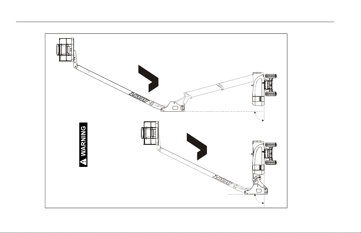
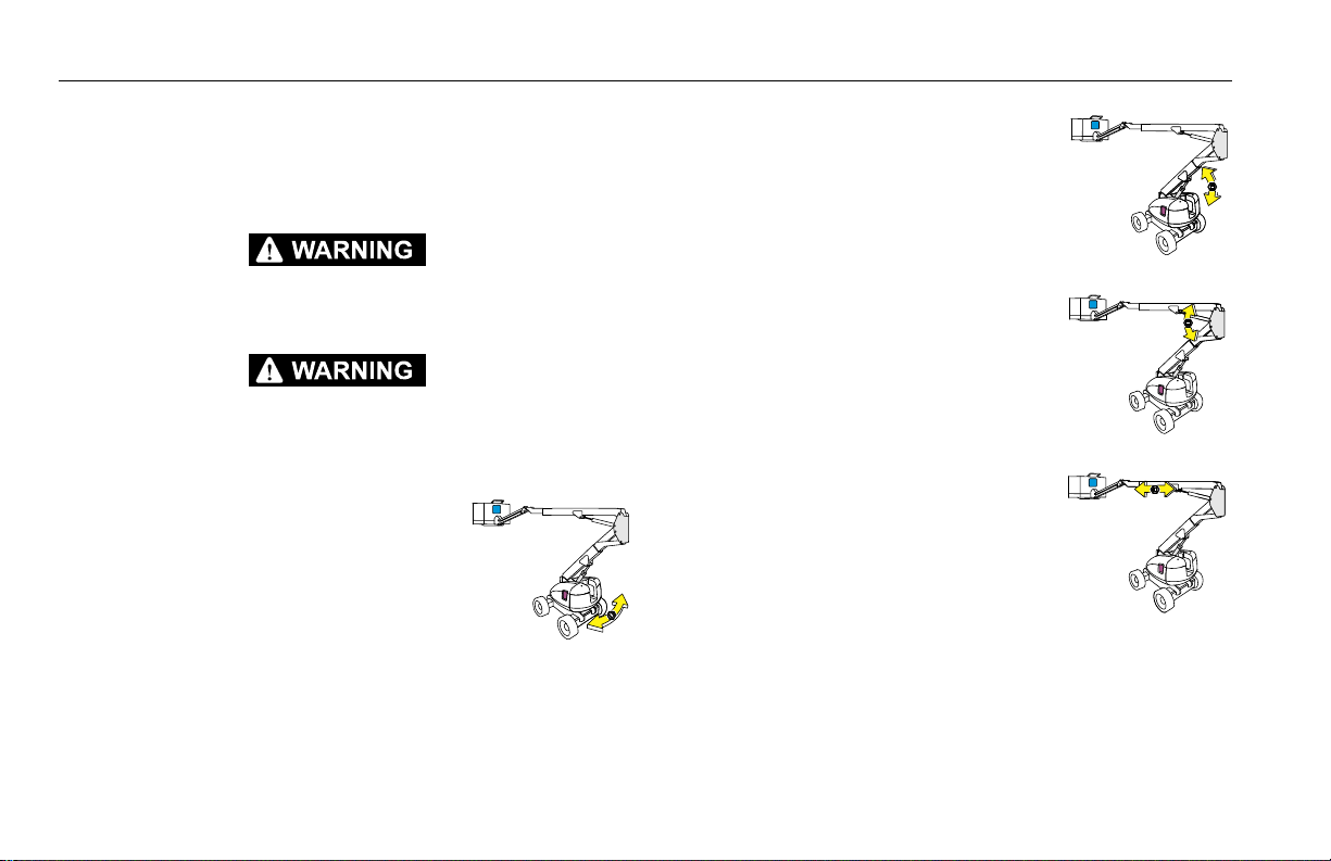
2. Raise the tower base boom to approximately 40 degrees,
then lower the tower boom back to the below horizontal
position. While raising and lowering the tower boom assembly, observe the position of the upright. Ensure that the
upright remains vertical relative to the chassis. Refer to Figure 2-5. and Figure 2-6.
3. Check that all machine functions are disabled when the
Emergency Stop Button is pushed in.
4. Check for proper operation of the auxiliary power and manual descent system (if equipped). Operate each function
control to ensure proper operation.
3121654 – JLG Lift – 2-9
SECTION 2 - USER RESPONSIBILITIES, MACHINE PREPARATION, AND INSPECTION
90°
90°
Figure 2-5. Boom Upright Positioning - Correct
UPRIGHT MUST BE 90° (VERTICAL) RELATIVE TO THE
CHASSIS.
CORRECT
CORRECT
2-10 – JLG Lift – 3121654
SECTION 2 - USER RESPONSIBILITIES, MACHINE PREPARATION, AND INSPECTION
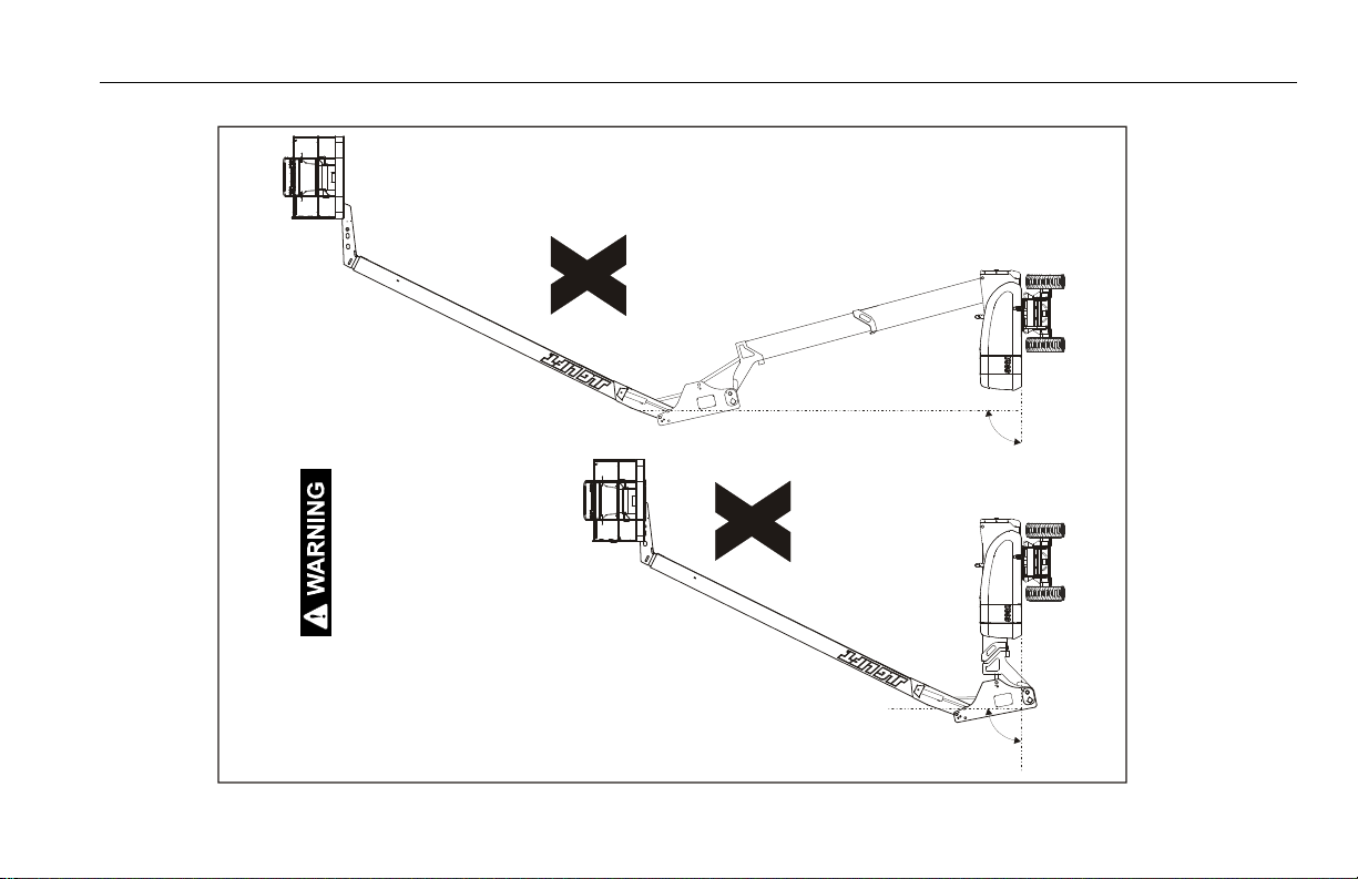
90°
90°
Figure 2-6. Boom Upright Positioning - Incorrect
TO AVOID TIPPING IF THIS OCCURS:
-LOWER PLATFORM TO GROUND USING MAIN BOOM LIFT
AND TELESCOPE FUNCTIONS. HAVE CONDITION COR-
RECTED BY A TRAINED JLG SERVICE TECHNICIAN BEFORE
CONTINUING USE OF MACHINE.
INCORRECT
INCORRECT
3121654 – JLG Lift – 2-11

SECTION 2 - USER RESPONSIBILITIES, MACHINE PREPARATION, AND INSPECTION
From the Platform Control Station:
1. Check that the control console is secure and all guards protecting the function switches or locks are in place. Ensure
that all function controls and switches return to the "off " or
neutral position when released.
DO NOT OPERATE MACHINE IF GUARDS OR LOCKS ARE MISSING OR THE SWITCHES DO
NOT RETURN TO THE "OFF" OR NEUTRAL POSITION
2. Check the footswitch adjustment and operation as follows:
a. With engine power shut down, attempt to start engine.
Engine should not attempt to start when footswitch is
activated.
b. Start engine. Activate hydraulic system by depressing
footswitch. Activate a boom function. Continue to activate the function and remove foot from footswitch. The
motion should stop.
DISCONTINUE OPERATION IF THE FOOTSWITCH DOES NOT OPERATE PROPERLY.
c. Check adjustment of footswitch. Footswitch must be
adjusted so that functions will operate when pedal is
approximately at its center of travel. If the footswitch
operates within last 1/4" of travel, top or bottom, it
should be adjusted.
NOTE: Footswitch has a 7 second delay timer. If a function is not acti-
vated within 7 seconds after depressing the footswitch, reset the
footswitch.
3. Ensure that all machine functions are disabled when the
Emergency Stop Button is activated.
4. Check auxiliary power for proper operation. Operate each
function control switch to ensure proper operation of the
auxiliary power system.
2-12 – JLG Lift – 3121654

SECTION 2 - USER RESPONSIBILITIES, MACHINE PREPARATION, AND INSPECTION
5. Drive forward and reverse; check for proper operation.
6. Steer left and right; check for proper operation.
7. Check the high-drive cutout for the tower boom assembly as
follows:
a. Place machine on level surface with booms retracted
and lowered.
b. From the platform control, position Drive Speed/Torque
Select switch to Fast (Forward Position).
c. Using extreme caution, partially position the DRIVE
control to Forward just enough to cause the machine to
move.
d. Raise the Tower Boom until the drive speed shifts from
high speed to slow or creep speed. The bottom of the
upright should NOT be above the hood level of the
machine.
8. Check the high-drive cutout for the main boom assembly as
follows:
a. Place machine on level surface with booms retracted
and lowered.
b. From the platform control, position Drive Speed/Torque
Select switch to Fast (Forward Position).
c. Raise the main boom above horizontal.
d. Using extreme caution, partially position the Drive con-
trol to Forward just enough to cause the machine to
move. The drive speed should be in slow or creep
mode.
9. Swing turntable to Left and Right a minimum of 45 degrees.
Check for smooth motion.
NOTE: Ensure the turntable lock is disengaged. To disengage lock, pull
snap pin from lock pin, lift lock pin up to unlock turntable. Return
snap pin to lock pin to hold lock pin in the disengaged position.
Reverse procedure to engage turntable lock.
3121654 – JLG Lift – 2-13

SECTION 2 - USER RESPONSIBILITIES, MACHINE PREPARATION, AND INSPECTION
10. Check the Tilt Alarm and Warning System as follows:
IF THE TILT ALARM AND WARNING SYSTEM DOES NOT OPERATE PROPERLY, DISCONTINUE OPERATION. CONTACT A QUALIFIED SERVICE TECHNICIAN TO CORRECT THE
MALFUNCTION BEFORE OPERATING THE MACHINE.
With the platform in the transport position (tower base
boom lowered, main fly boom retracted, and main base
boom below horizontal) drive up a suitable ramp of at least
5° slope. The tilt indicator light on the platform control console should illuminate.
11. Check that the platform automatically levels properly during
raising and lowering of the boom.
12. Check that the platform level override operates properly.
13. Check platform rotator for smooth operation and assure
platform will rotate 90 degrees in both directions from centerline of boom.
14. If equipped with 4-wheel steer, check rear steer left and right
for proper operation.
15. If equipped, raise and lower the articulating jib boom. Check
for smooth operation.
16. If equipped with Auxiliary Power, operate each function control switch to assure that they function in both directions
using auxiliary power instead of engine power.
17. Ground Controls - Place Ground/Platform Select switch to
Ground. Start engine. Platform controls should not operate.
2-14 – JLG Lift – 3121654

SECTION 2 - USER RESPONSIBILITIES, MACHINE PREPARATION, AND INSPECTION
2.4 OSCILLATING AXLE LOCKOUT TEST (IF EQUIPPED)
LOCKOUT SYSTEM TEST MUST BE PERFORMED QUARTERLY, ANY TIME A SYSTEM COMPONENT IS REPLACED, OR WHEN IMPROPER SYSTEM OPERATION IS SUSPECTED.
NOTE: Ensure boom is fully retracted, lowered, and centered between
drive wheels prior to beginning lockout cylinder test.
1. Place a 6 inch (15.2 cm) high block with ascension ramp in
front of left front wheel.
2. From platform control station, start engine.
3. Position Drive Speed/Torque Select switch to Slow.
4. Place Drive control lever to Forward position and carefully
drive machine up ascension ramp until left front wheel is on
top of block.
5. Carefully activate Swing control lever and position boom
over Right side of machine.
6. With boom over right side of machine, place Drive control
lever to Reverse and drive machine off of block and ramp.
7. Have an assistant check to see that left front or right rear
wheel remains elevated in position off of ground.
8. Carefully activate Swing control lever and return boom to
stowed position (centered between drive wheels). When
boom reaches center, stowed position, lockout cylinders
should release and allow wheel to rest on ground, it may be
necessary to activate Drive to release cylinders.
9. Place the 6 inch (15.2 cm) high block with ascension ramp in
front of right front wheel.
10. Place Drive control lever to Forward and carefully drive
machine up ascension ramp until right front wheel is on top
of block.
11. Carefully activate Swing control lever and position boom
over left side of machine.
12. With boom over left side of machine, place Drive control
lever to Reverse and drive machine off of block and ramp.
13. Have an assistant check to see that right front or left rear
wheel remains elevated in position off of ground.
14. Carefully activate Swing control lever and return boom to
stowed position (centered between drive wheels). When
boom reaches center, stowed position, lockout cylinders
should release and allow wheel to rest on ground, it may be
necessary to activate Drive to release cylinders.
15. If lockout cylinders do not function properly, have qualified
personnel correct the malfunction prior to any further operation.
3121654 – JLG Lift – 2-15

SECTION 2 - USER RESPONSIBILITIES, MACHINE PREPARATION, AND INSPECTION
2.5 INSPECTION AND USE OF FALL ARREST SYSTEM
The external fall arrest system is designed to provide a lanyard attach
point while allowing the operator to access areas outside the plat-
form. Exit/Enter the platform through the gate area only. The system
is designed for use by one person.
Personnel must use fall protection at all times. A full body harness
and shock absorbing lanyard, not to exceed 6 feet (1.8 m) in
length, is required when using the external fall arrest system.
DO NOT OPERATE ANY MACHINE FUNCTIONS WHILE OUTSIDE OF PLATFORM. BE
CAREFUL WHEN ENTERING/EXITING THE PLATFORM AT ELEVATION.
THE EXTERNAL FALL ARREST SYSTEM REQUIRES AN ANNUAL INSPECTION AND CERTIFICATION. THE ANNUAL INSPECTION AND CERTIFICATION MUST BE PERFORMED BY A
COMPETENT PERSON.
If inspection services are required, contact:
Latchways plc
Hopton Park
Devises
Wiltshire
SN10 2JP
United Kingdom
Tel: +44 (0)1380 732700
Fax: +44 (0)1380 732701
e-mail: info@latchways.com
Prior to accessing areas outside of the fall arrest platform, the
user(s) must complete an appropriate job plan/risk assessment
for the work to be accomplished and the environment at hand. It
is the user’s responsibility to completely and adequately complete the job plan/risk assessment - special consideration must
be given to the arresting distance of the deployed shock
absorbing lanyard compared to the proximity of lower levels, or
the ground, in the event of a fall.
2-16 – JLG Lift – 3121654

SECTION 2 - USER RESPONSIBILITIES, MACHINE PREPARATION, AND INSPECTION
Inspecting Cable Tension and Slip Indicator
IF THE FALL ARREST SYSTEM IS USED TO ARREST A FALL OR IS OTHERWISE DAMAGED,
THE ENTIRE SYSTEM MUST BE REPLACED AND THE PLATFORM FULLY INSPECTED.
REFER TO THE SERVICE MANUAL.
Prior to Use Inspection
Fall arrest systems must be inspected prior to each use. Replace if
there are any signs of wear or damage to any of the components.
Prior to use inspection should include a visual inspection of the
following items:
Cable: Proper tension, broken strands, corrosion.
Fittings: Loose fittings and fractures, damage to
hanger
Transfastener: Damage, free and proper sliding
Attaching Hardware: Loose, missing, properly
tightened
Cable tension is adjusted by using the Line Tenser. The Line
Tenser is the disc at the end of the cable (shown below). When
proper tension is achieved, the disc will spin by hand. When less
than proper tension is present the disc will not turn by hand. The
cable will stretch normally over time. In order to tension the cable
the turnbuckle can be tightened. Rotate the turnbuckle until the
proper tension is achieved.
3121654 – JLG Lift – 2-17

SECTION 2 - USER RESPONSIBILITIES, MACHINE PREPARATION, AND INSPECTION
The slip indicator is the short tube crimped beside the end connection of the cable. If the cable slips from the end connection a
gap will be present between the slip indicator and the end connection. No gap is acceptable. A cable that has slipped must be
taken out of service immediately and the system replaced.
Shown below is the slip indicator as it should appear.
Shown below is the slip indicator with a gap, signifying that the
fall arrest system should be replaced immediately.
2-18 – JLG Lift – 3121654

SECTION 2 - USER RESPONSIBILITIES, MACHINE PREPARATION, AND INSPECTION
Figure 2-7. Fall Arrest System
1. Transfastener
2. Bracket
3. Cable
4. Swage/Slip Indicator
5. Turnbuckle
6. Line Tenser
3121654 – JLG Lift – 2-19

SECTION 2 - USER RESPONSIBILITIES, MACHINE PREPARATION, AND INSPECTION
NOTES:
2-20 – JLG Lift – 3121654

SECTION 3 - MACHINE CONTROLS AND INDICATORS
SECTION 3. MACHINE CONTROLS AND INDICATORS
3.1 GENERAL
THE MANUFACTURER HAS NO DIRECT CONTROL OVER MACHINE APPLICATION AND
OPERATION. THE USER AND OPERATOR ARE RESPONSIBLE FOR CONFORMING WITH
GOOD SAFETY PRACTICES.
This section provides the necessary information needed to
understand control functions.
3.2 CONTROLS AND INDICATORS
NOTE: All machines are equipped with control panels that use symbols
to indicate control functions. On ANSI machines refer to decal
located on the control box guard in front of the control box or by
the ground controls for these symbols and the corresponding
functions.
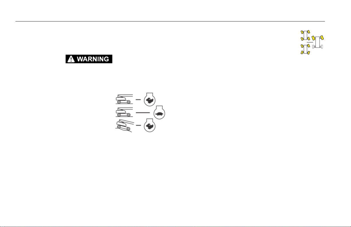
NOTE: The indicator panels use different shaped symbols to alert the
operator to different types of operational situations that could
arise. The meaning of those symbols are explained below.
Indicates a potentially hazardous situation, which if
not corrected, could result in serious injury or death.
This indicator will be red.
Indicates an abnormal operating condition, which if
not corrected, may result in machine interruption or
damage. This indicator will be yellow.
Indicates important information regarding the operating condition, i.e. procedures essential for safe operation. This indicator will be green with the exception of
the capacity indicator which will be green or yellow
depending upon platform position.
3121654 – JLG Lift – 3-1

SECTION 3 - MACHINE CONTROLS AND INDICATORS
TO AVOID SERIOUS INJURY, DO NOT OPERATE MACHINE IF ANY CONTROL LEVERS OR
TOGGLE SWITCHES CONTROLLING PLATFORM MOVEMENT DO NOT RETURN TO THE
OFF POSITION WHEN RELEASED.
Ground Control Console
(See Figure 3-1., Ground Control Console)
NOTE: If equipped, the Function Enable switch must be
held down in order to operate Main Boom Telescope, Tower Lift, Swing, Main Lift, Jib Lift, Platform Level Override, and Platform Rotate functions.
1. Platform Rotate
Provides rotation of the platform.
ONLY USE THE PLATFORM LEVELING OVERRIDE FUNCTION FOR SLIGHT LEVELING OF
THE PLATFORM. INCORRECT USE COULD CAUSE THE LOAD/OCCUPANT TO SHIFT OR
FALL. FAILURE TO DO SO COULD RESULT IN DEATH OR SERIOUS INJURY.
2. Platform Leveling Override
A three position switch allows the
operator to adjust the automatic self
leveling system. This switch is used to
adjust platform level in situations
such as ascending/descending a
grade.
3. Jib (If Equipped)
This switch provides raising and lowering of the jib.
3-2 – JLG Lift – 3121654
SECTION 3 - MACHINE CONTROLS AND INDICATORS
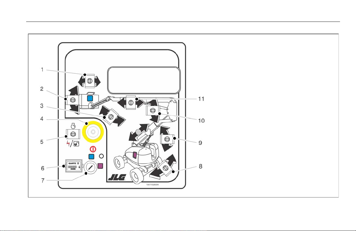
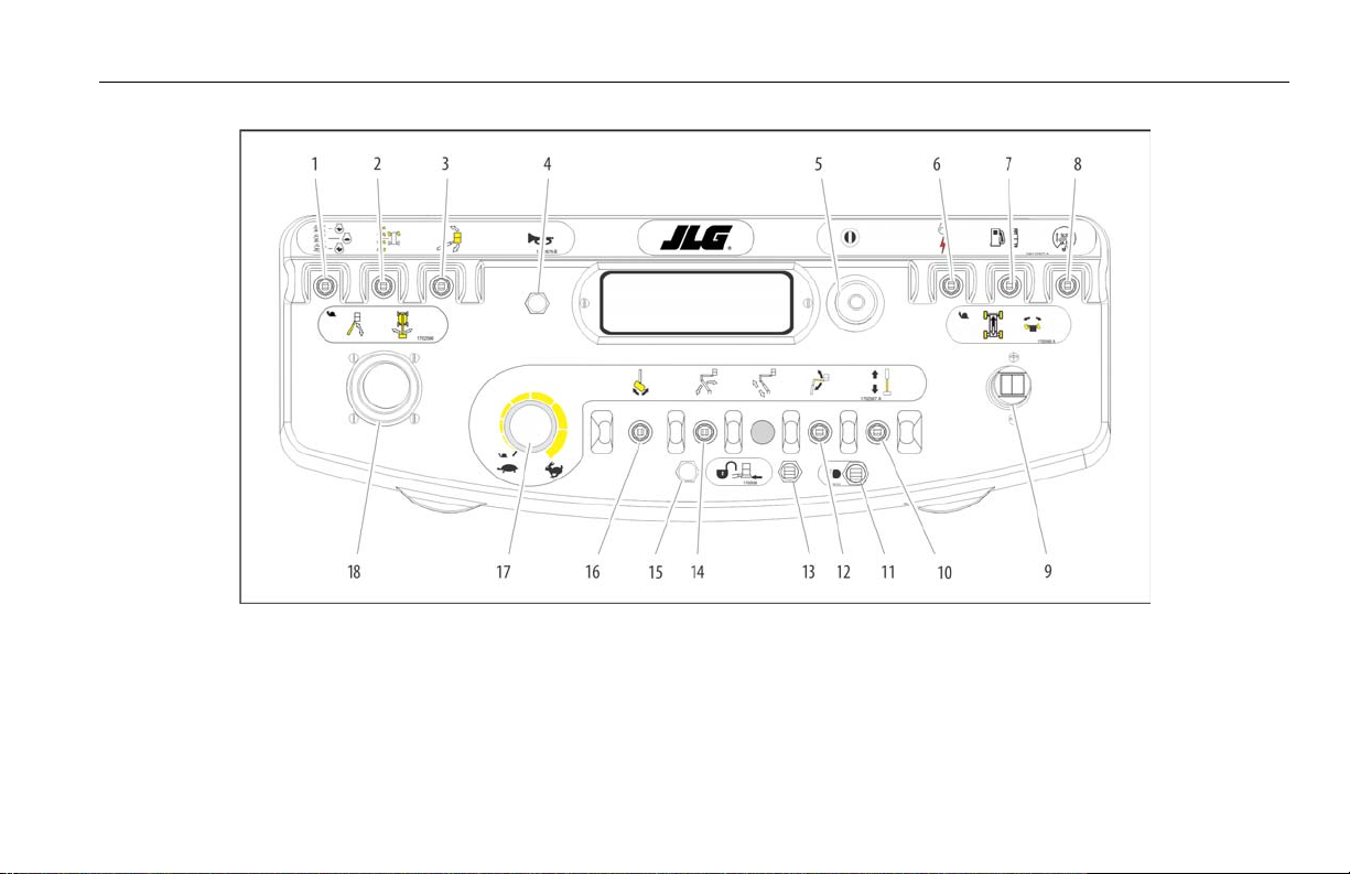
Figure 3-1. Ground Control Console
1. Platform Rotate
2. Platform Leveling Override
3. Jib
4. Power/Emergency Stop
5. Engine Start/Auxiliary Power Switch/Function Enable
6. Hourmeter
7. Platform/Ground Select
8. Swing
9. Tower Lift
10. Main Boom Lift
11. Main Boom Telescope
3121654 – JLG Lift – 3-3
SECTION 3 - MACHINE CONTROLS AND INDICATORS
NOTE: When Power/Emergency Stop switch is in the “On” position and
engine is not running, an alarm will sound, indicating Ignition is
“On”.
WHEN THE MACHINE IS SHUT DOWN THE MASTER/EMERGENCY STOP SWITCH MUST
BE POSITIONED TO THE “OFF” POSITION TO PREVENT DRAINING THE BATTERY.
NOTE: On machines with diesel engines, when Glow Plug Indicator is
lighted (Yellow), wait until light goes out before cranking engine.
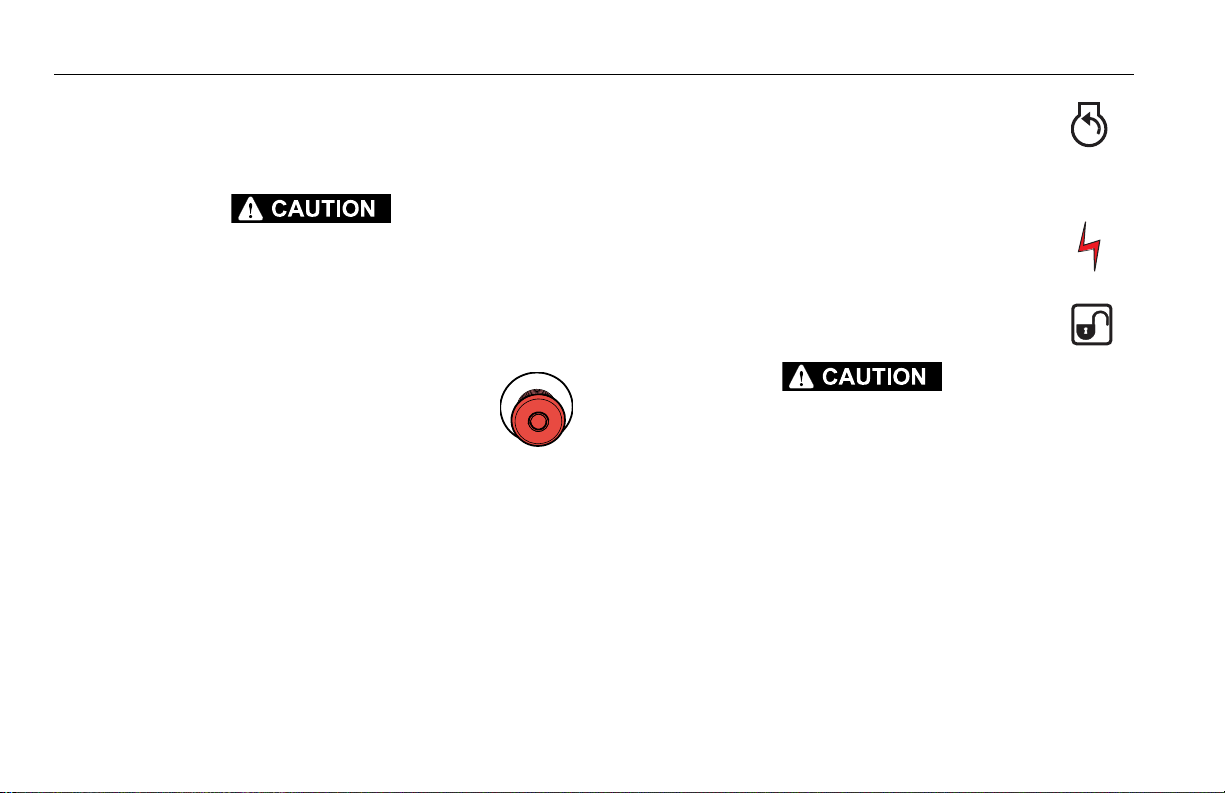
4. Power/Emergency Stop Switch
A two-position red mushroom shaped switch
supplies power to Platform/Ground Select
switch when pulled out (on). When pushed in
(off), power is shut off to the Platform/Ground Select switch.
5. Engine Start/ Auxiliary Power Switch /Function
Enable
To start the engine, the switch must be held "Up" until the
engine starts.
To use auxiliary power, the switch must be
held “Down” for duration of auxiliary pump
use.
When the engine is running, the switch must
be held "Down" to enable all boom controls.
WHEN OPERATING ON AUXILIARY POWER, DO NOT OPERATE MORE THAN ONE FUNCTION AT A TIME. (SIMULTANEOUS OPERATION CAN OVERLOAD THE AUXILIARY PUMP
MOTOR.)
3-4 – JLG Lift – 3121654
SECTION 3 - MACHINE CONTROLS AND INDICATORS
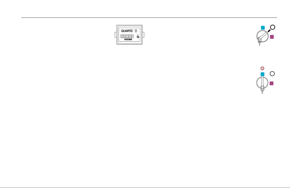
6. Hourmeter
Registers the amount of time the
machine has been in use, with engine
running. By connecting into the oil
pressure circuit of the engine, only engine run hours are
recorded. The hourmeter registers up to 9,999.9 hours and
cannot be reset.
NOTE: When the Platform/Ground Select Switch is in the
center position, power is shut off to the controls at
both operating stations. Remove the key to prevent the controls from being actuated. The key is
removable in the platform position on CE specification machines. The key must be available to
ground personnel in the event of an emergency.
7. Platform/Ground Select Switch
The three position, key operated switch supplies power to the platform control console
when positioned to Platform. With the switch
key turned to the Ground position only
ground controls are operable.
3121654 – JLG Lift – 3-5
SECTION 3 - MACHINE CONTROLS AND INDICATORS
NOTE: Main Lift, Tower Lift, Swing, Platform Level, Main Telescope,
Tower Telescope, Platform Rotate, and Auxiliary Power control
switches are spring-loaded and will automatically return to neutral (off) when released.
WHEN OPERATING THE BOOM ENSURE THERE ARE NO PERSONNEL AROUND OR
UNDER PLATFORM.
TO AVOID SERIOUS INJURY, DO NOT OPERATE MACHINE IF ANY CONTROL LEVERS OR
TOGGLE SWITCHES CONTROLLING PLATFORM MOVEMENT DO NOT RETURN TO THE
OFF POSITION WHEN RELEASED.
8. Swing Control
Provides 360 degrees continuous
turntable rotation.
9. Towe r Lif t
This switch provides raising and lowering of the tower boom. This function works only when the tower
boom is fully retracted.
10. Main Boom Lift Control
Provides raising and lowering of the
main boom.
11. Main Telescope Control
Provides extension and retraction of
the main boom.
3-6 – JLG Lift – 3121654
SECTION 3 - MACHINE CONTROLS AND INDICATORS
Ground Control Indicator Panel
(See Figure 3-2., Ground Control Indicator Panel)
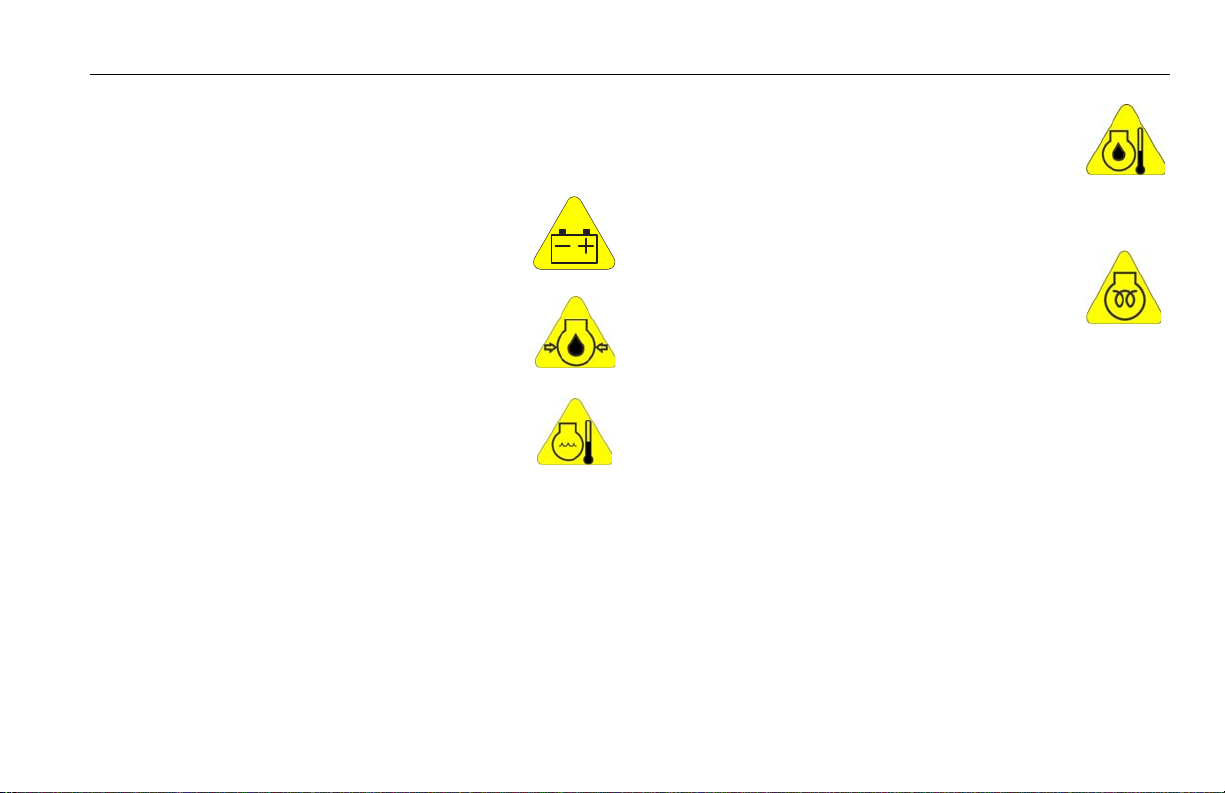
1. No Alternator Output Indicator
Indicates a problem in the charging circuit,
and service is required.
2. Engine Oil Pressure Indicator
Indicates that engine oil pressure is below normal and service is required.
3. High Engine Coolant Temperature Indicator
(Liquid Cooled Engines)
Indicates that engine coolant temperature is
abnormally high and service is required.
4. Engine Oil Temperature Indicator (Deutz, If
Equipped)
Indicates that the temperature of the engine
oil, which also serves as engine coolant, is
abnormally high and service is required.
5. Glow Plug/ Wait to Start Indicator
Indicates the glow plugs are on. The glow
plugs are automatically turned on with the
ignition circuit and remain on for approximately seven seconds. Start the engine only after the light
goes out.
3121654 – JLG Lift – 3-7
SECTION 3 - MACHINE CONTROLS AND INDICATORS
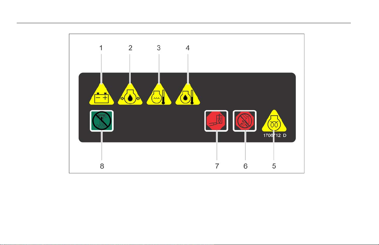
1. No Alter nator Output
2. Low Engine Oil Pressure
3. High Engine Coolant Temperature
4. High Engine O il Temperature
5. Glow Plug
6. Boom Malfunc tion
7. Platform Overload
8. Drive and Steer Disable
Figure 3-2. Ground Control Indicator Panel
3-8 – JLG Lift – 3121654

SECTION 3 - MACHINE CONTROLS AND INDICATORS
6. Boom Malfunction Indicator
If the Boom Malfunction Indicator illuminates when attempting to activate a tower
boom function, the function is being cutout
by tower boom limit switch. The function is not permitted at
the current boom configuration.
If the Boom Malfunction Indicator is flashing or on steady
without a boom function attempt, the upright is out of
al ig nm en t or th e m on it or in g s ys te m i s i n n ee d o f c al ib ra ti on .
DISCONTINUE OPERATION IF THE BOOM MALFUNCTION LIGHT IS FLASHING OR ON
STEADY.
IF THE UPRIGHT IS OUT OF ALIGNMENT WITH THE PLATFORM RAISED, LOWER THE
MAIN BOOM AND TELESCOPE OUT UNTIL THE PLATFORM REACHES THE GROUND. THE
TOWER BOOM DOWN FUNCTION IS CUT OUT IN THIS CONDITION. REPORT THE PROBLEM TO THE PROPER SERVICE PERSONNEL. DO NOT OPERATE THE MACHINE UNTIL
THE MALFUNCTION IS CORRECTED.
7. Platform Overload Indicator. (If Equipped)
Indicates the platform has been overloaded.
8. Drive and Steer Disable Indicator (If equipped)
Indicates the Drive and Steer Disable function
has been activated.
3121654 – JLG Lift – 3-9
SECTION 3 - MACHINE CONTROLS AND INDICATORS
Platform Console
(See Figure 3-3.)
TO AVOID SERIOUS INJURY, DO NOT OPERATE MACHINE IF ANY CONTROL LEVERS OR
TOGGLE SWITCHES CONTROLLING PLATFORM MOVEMENT DO NOT RETURN TO THE
OFF OR NEUTRAL POSITION WHEN RELEASED.
1. Drive Speed/Torque Select
The machine has a two position
switch - The forward position
gives maximum drive speed. The
back position gives maximum
torque for rough terrain and
climbing grades.
2. Steer Select (If Equipped)
When equipped with four wheel steering, the
action of the steering system is operator
selectable. The center switch position gives
conventional front wheel steering with the rear wheels unaffected. This is for normal driving at maximum speeds. The
forward position is for “crab” steering. When in this mode
both front and rear axles steer in the same direction, which
allows the chassis to move sideways as it goes forward. This
can be used for positioning the machine in aisle ways or
against buildings. The back switch position is for “coordinated” steering. In this mode the front and rear axles steer in
the opposite directions to produce the tightest turning circle for maneuvering in confined areas.
To re-synchronize the front and rear axles, position the rear
drive wheels to the forward drive position by selecting
either crab or compound steer, then select front steer (center switch position) to operate the normal steering function.
3-10 – JLG Lift – 3121654
SECTION 3 - MACHINE CONTROLS AND INDICATORS
1. Drive Speed / Torque Select
2. Steer Selec t
3. Platform Level Override
4. Horn
5. Power/Emergency Stop
6. Engine Start / Aux Power
7. Fuel Select
8. Drive Orientation Override
9. Drive/Steer
10. Telescope
11. Lights
12. Jib (800AJ)
13. Soft Touch Override
14. Tower Lift
15. Soft Touch Indicator
16. Platform Rotate
17. Function Speed Control
18. Main Lift / Swing
Figure 3-3. Platform Control Console
3121654 – JLG Lift – 3-11

SECTION 3 - MACHINE CONTROLS AND INDICATORS
6. Engine Start/Auxiliary Power
ONLY USE THE PLATFORM LEVELING OVERRIDE FUNCTION FOR SLIGHT LEVELING OF
THE PLATFORM. INCORRECT USE COULD CAUSE THE LOAD/OCCUPANTS TO SHIFT OR
FALL. FAILURE TO DO SO COULD RESULT IN DEATH OR SERIOUS INJURY.
3. Platform Leveling Override
A three position switch allows the operator to
adjust the automatic self leveling system. This
switch is used to adjust platform level in situations such as ascending/descending a grade.
4. Horn
A push-type Horn switch supplies electrical
power to an audible warning device when pressed.
5. Power/Emergency Stop Switch
A two-position red mushroom shaped switch
furnishes power to Platform Controls when
pulled out (on). When pushed in (off ), power is
shut off to the platform functions.
When pushed forward, the switch energizes
the starter motor to start the engine.
The Auxiliary Power control switch energizes
the electrically operated hydraulic pump.
(Switch must be held on for duration of auxiliary pump use.)
The auxiliary pump functions to provide sufficient oil flow to
operate the basic machine functions should the main pump
or engine fail. The auxiliary pump will operate tower boom
lift, tower telescope, main boom lift, main telescope and
swing.
7. Fuel Select (Dual Fuel Engine Only) (If
Equipped)
Gasoline or liquid propane fuel may be
selected by moving the switch to the appropriate position. It
is unnecessary to purge the fuel system before switching
fuels, so there is no waiting period when switching fuels
while the engine is running.
3-12 – JLG Lift – 3121654

SECTION 3 - MACHINE CONTROLS AND INDICATORS
8. Drive Orientation Override
When the boom is swung over the rear tires or
further in either direction, the Drive Orientation indicator will illuminate when the drive
function is selected. Push and release the switch, and within
3 seconds move the Drive/Steer control to activate drive or
steer. Before driving, locate the black/white orientation
arrows on both the chassis and the platform controls. Move
the drive controls in a direction matching the directional
arrows.
NOTE: Lift, Swing, and Drive control levers are spring-loaded and will
automatically return to neutral (off) position when released.
TO AVOID SERIOUS INJURY, DO NOT OPERATE MACHINE IF ANY CONTROL LEVERS OR
TOGGLE SWITCHES CONTROLLING PLATFORM MOVEMENT DO NOT RETURN TO THE
OFF OR NEUTRAL POSITION WHEN RELEASED.
NOTE: To operate the Drive joystick, pull up on the lock-
ing ring below the handle.
NOTE: The Drive joystick is spring loaded and will automatically return
to neutral (off) position when released.
9. Drive/Steer
Push forward to drive forward,
pull back to drive in reverse.
Steering is accomplished via a
thumb-activated rocker switch on
the end of the steer handle.
3121654 – JLG Lift – 3-13

SECTION 3 - MACHINE CONTROLS AND INDICATORS
10. Main Boom Telescope
Provides extension and retraction of the main
boom.
11. Lights (If Equipped)
This switch operates control console panel
lights and head lights if the machine is so
equipped. The ignition switch does not have to be on to
operate the lights, so care must be taken to avoid draining
the battery if left unattended. The master switch and / or the
ignition switch at the ground control will turn off power to
all lights.
12. Jib (If Equipped)
Push forward to lift up, pull back to lift down.
Variable lift speed is using the Function Speed
Control.
13. Soft Touch Override Switch (If equipped)
This switch enables the functions that
were cut out by the Soft Touch system to
operate again at creep speed, allowing the operator to move
the platform away from the obstacle that caused the shutdown situation.
14. Towe r Lif t
This switch provides for raising and lowering of
the tower boom when positioned to “up” or
“down”. Tower Lift must be fully elevated “up”
before operating Tower Telescope. (Tower Lift should not
function when Tower Telescope is extended).
3-14 – JLG Lift – 3121654

SECTION 3 - MACHINE CONTROLS AND INDICATORS
15. Soft Touch Indicator (If Equipped)
Indicates the Soft Touch bumper is against
an object. All controls are cut out until the
override button is pushed, at which time controls are active
in the Creep Mode.
16. Platform Rotate
Provides rotation of the platform when positioned to the right or left.
17. Function Speed Control
This control affects the speed of telescope
and platform rotate. Turning the knob all
the way counterclockwise until it clicks puts
drive, main lift and swing into creep mode.
NOTE: To operate the Main Boom Lift/Swing joystick,
pull up on the locking ring below the handle.
NOTE: The Main Boom Lift/Swing joystick is spring
loaded and will automatically return to neutral
(off) position when released.
18. Main Lift/Swing Controller
Provides main lift and swing. Push
forward to lift up, pull backward
to boom down. Move right to
swing right, move left to swing
left. Moving the joystick activates
switches to provide the functions
selected.
NOTE: Main boom lift and swing functions may be selected in combi-
nation. Maximum speed is reduced when multiple functions are
selected.
3121654 – JLG Lift – 3-15

SECTION 3 - MACHINE CONTROLS AND INDICATORS
Platform Console Indicator Panel
(See Figure 3-4., Platform Console Indicator Panel)
1. Tilt Alarm Warning Light and Alarm
This illuminator indicates that the chassis is on
a slope. An alarm will also sound when the
chassis is on a slope and the boom is above
horizontal. If lit when boom is raised or extended, retract
and lower to below horizontal then reposition machine so
that it is level before continuing operation. If the boom is
above horizontal and the machine is on a slope, the tilt
alarm warning light will illuminate and an alarm will sound
and CREEP is automatically activated.
IF TILT WARNING LIGHT IS ILLUMINATED WHEN BOOM IS RAISED OR EXTENDED,
RETRACT AND LOWER TO BELOW HORIZONTAL THEN REPOSITION MACHINE SO THAT
IT IS LEVEL BEFORE EXTENDING BOOM OR RAISING BOOM ABOVE HORIZONTAL.
NOTE: In certain markets, when the tilt sensor alarm is activated the
Drive function will be disabled if the boom is elevated above horizontal.
2. Platform Overload (If equipped)
Indicates the platform has been overloaded.
3. Boom Malfunction Indicator
When an audible alarm sounds and the Boom
Malfunction Indicator illuminates when
attempting to activate a tower boom function,
the function is being cutout by tower boom limit switch. This
function is not permitted at the current boom configuration.
When an audible alarm sounds and the Boom Malfunction
Indicator illuminates steady without a boom function
attempt, the upright is out of alignment.
DISCONTINUE OPERATION IF THE UPRIGHT IS OUT OF ALIGNMENT OR THE BOOM
MALFUNCTION LIGHT REMAINS ILLUMINATED.
IF THE UPRIGHT IS OUT OF ALIGNMENT WITH THE PLATFORM RAISED, LOWER THE
MAIN BOOM AND TELESCOPE OUT UNTIL THE PLATFORM REACHES THE GROUND. THE
TOWER BOOM DOWN FUNCTION IS CUT OUT IN THIS CONDITION. REPORT THE PROBLEM TO THE PROPER SERVICE PERSONNEL. DO NOT OPERATE THE MACHINE UNTIL
THE CONDITION IS CORRECTED.
3-16 – JLG Lift – 3121654

SECTION 3 - MACHINE CONTROLS AND INDICATORS
1. Tilt
2. Overload
3. Boom Malfunctgion
4. Capacity
5. Enable
6. Glow Plug
7. Low Fuel
8. System Distress
9. AC Generator
10. Drive Orientation
11. Creep
Figure 3-4. Platform Console Indicator Panel
3121654 – JLG Lift – 3-17

SECTION 3 - MACHINE CONTROLS AND INDICATORS
4. Capacity Indicator
Indicates the maximum platform capacity for
the current position of the platform.
Restricted capacities are permitted at
restricted platform positions (shorter boom
lengths and higher boom angles).
NOTE: Refer to the capacity decals on the machine for
restricted and unrestricted platform capacities.
5. Footswitch/Enable Indicator
To operate any function, the footswitch must
be depressed and the function selected within
seven seconds. The enable indicator shows
that the controls are enabled. If a function is not selected
within seven seconds, or if a seven second lapse between
ending one function and beginning the next function, the
enable light will go out and the footswitch must be released
and depressed again to enable the controls.
Releasing the footswitch removes power from all controls
and applies the drive brakes.
TO AVOID SERIOUS INJURY, DO NOT REMOVE, MODIFY OR DISABLE THE FOOTSWITCH
BY BLOCKING OR ANY OTHER MEANS.
FOOTSWITCH MUST BE ADJUSTED IF FUNCTIONS ACTIVATE WHEN SWITCH ONLY
OPERATES WITHIN LAST 1/4" OF TRAVEL, TOP OR BOTTOM.
3-18 – JLG Lift – 3121654
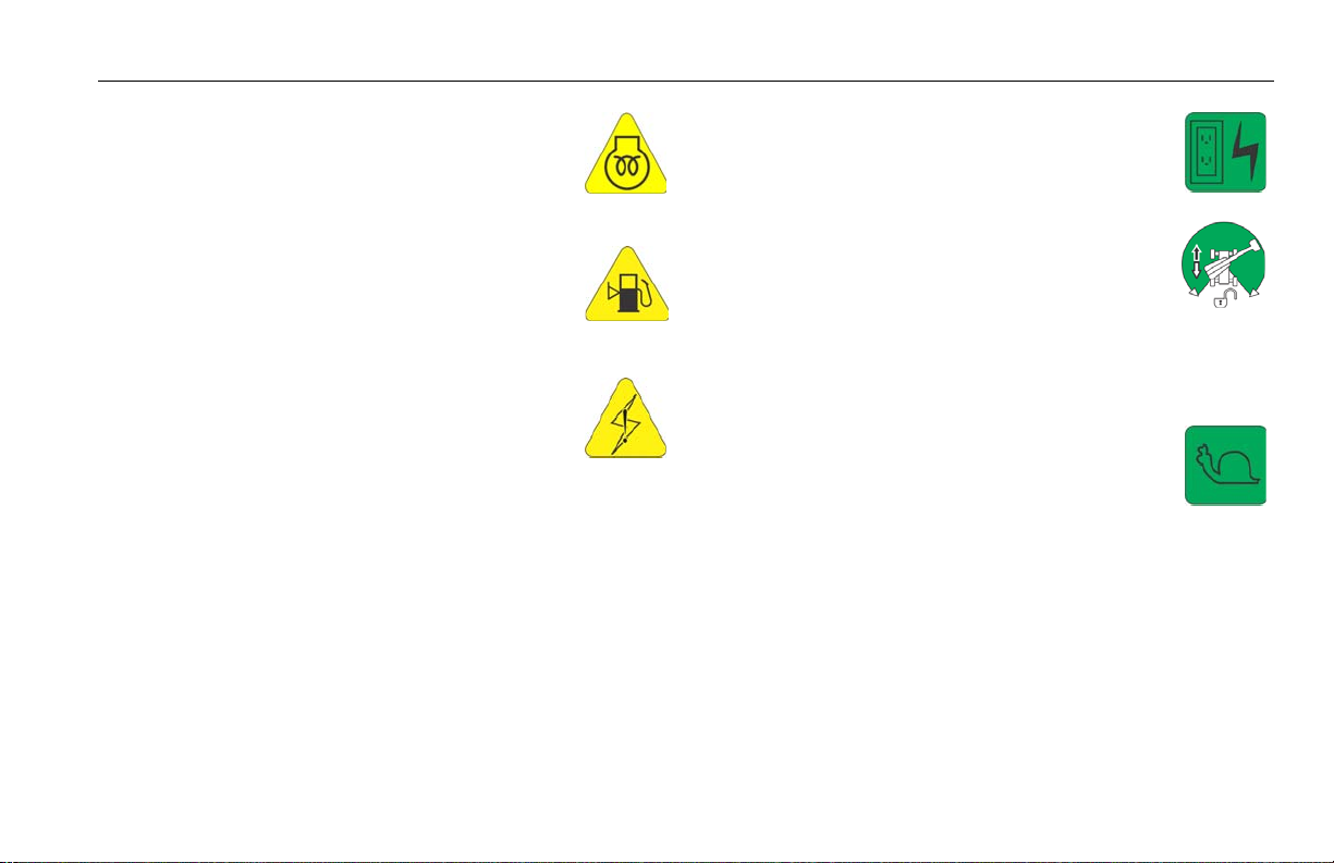
SECTION 3 - MACHINE CONTROLS AND INDICATORS
6. Glow Plug/Wait to Start Indicator
Indicates the glow plugs are operating. After
turning on ignition, wait until light goes out
before cranking engine.
7. Low Fuel Indicator (Yellow)
Indicates the fuel tank is 1/8 full or less. When
the light first turns on, there are approximately
four usable gallons of fuel remaining.
8. System Distress Indicator
The light indicates that the JLG Control System
has detected an abnormal condition and a
Diagnostic Trouble Code has been set in the
system memory. Refer to the Service Manual for instructions
concerning the trouble codes and trouble code retrieval.
9. AC Generator (If Equipped)
Indicates the generator is in operation.
10. Drive Orientation Indicator
When the boom is swung beyond the rear
drive tires or further in either direction, the
Drive Orientation indicator will illuminate
when the drive function is selected. This is a signal for the
operator to verify that the drive control is being operated in
the proper direction (i.e. controls reversed situations).
11. Creep Speed Indicator
When the Function Speed Control is turned to
the creep position, the indicator acts as a
reminder that all functions are set to the slowest speed.
3121654 – JLG Lift – 3-19

SECTION 3 - MACHINE CONTROLS AND INDICATORS
NOTES:
3-20 – JLG Lift – 3121654

SECTION 4. MACHINE OPERATION
SECTION 4 - MACHINE OPERATION
4.1 DESCRIPTION
This machine is a self-propelled hydraulic personnel lift equipped
with a work platform on the end of an elevating and rotating
boom.
The primary operator control station is in the platform. From this
control station, the operator can drive and steer the machine in
both forward and reverse directions. The operator can raise or
lower the boom or swing the boom to the left or right. Standard
boom swing is 360 degree continuous rotation. The machine has
a Ground Control Station which will override the Platform Control
Station. Ground Controls operate Boom Lift and Swing, and are to
be used in an emergency to lower the platform to the ground
should the operator in the platform be unable to do so.
4.2 BOOM OPERATING CHARACTERISTICS AND LIMITATIONS
Capacities
Raising boom above horizontal with or without any load in platform, is based on the following criteria:
1. Machine is positioned on a smooth, firm and level surface.
2. Load is within manufacturer’s rated capacity.
3. All machine systems are functioning properly.
4. Proper tire pressure.
5. Machine is as originally equipped from JLG
Stability
Machine stability is based on two positions which are called FORWARD STABILITY and BACKWARD STABILITY. The machine position of least forward stability is shown in Figure 4-1. and its
positions of least backward stability is shown in Figure 4-2.
TO AVOID FORWARD OR BACKWARD TIPPING, DO NOT OVERLOAD MACHINE OR OPERATE ON AN OUT-OF-LEVEL SURFACE.
3121654 – JLG Lift – 4-1
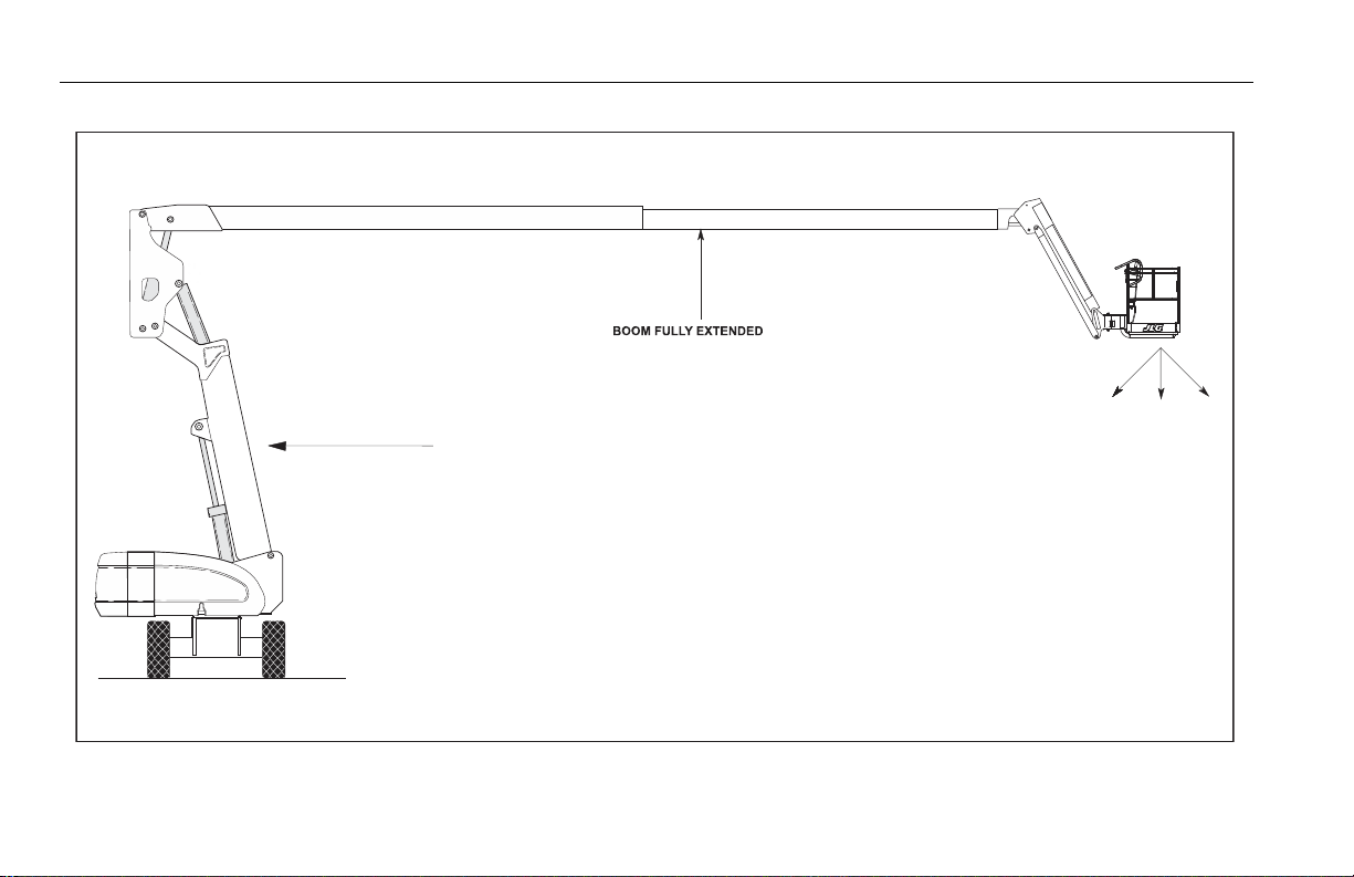
SECTION 4 - MACHINE OPERATION
AT HORIZONTAL (0 DEGREES)
MACHINE WILL UPSET IN THIS
DIRECTION IF OVERLOADED
OR OPE RATE D ON AN
OUT- OF-LEVEL SURFACE.
LEVEL SURFACE
TOWER BOO M
A T MAX ANGLE
Figure 4-1. Position of Least Forward Stability
4-2 – JLG Lift – 3121654
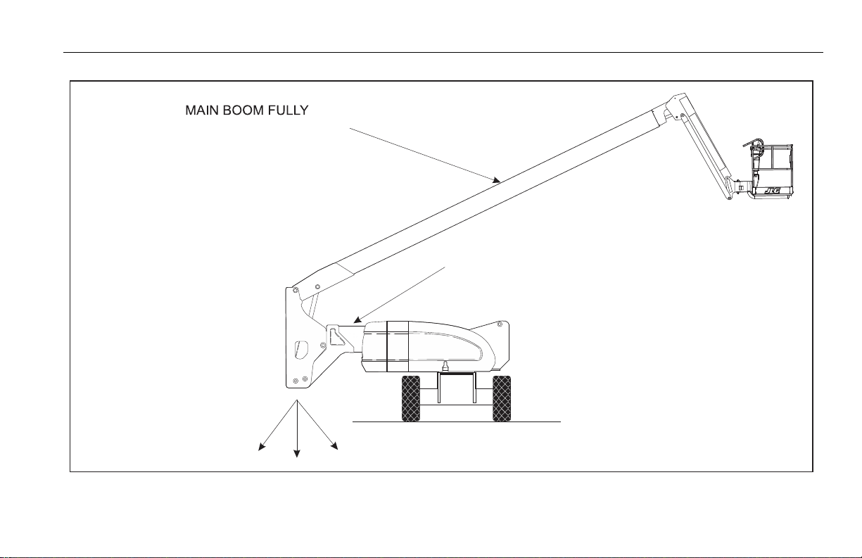
RET RA CTED AND F ULLY
RETRACTED
TOWER BOOM FULLY
LOWERED
LEVEL SURFACE
MACHINE WILL UPS E T
IN THIS DIRECTION IF
OPERAT ED ON AN
OUT-OF -LEVEL SURFACE
Figure 4-2. Positions of Least Backward Stability (Sheet 1 of 2)
SECTION 4 - MACHINE OPERATION
3121654 – JLG Lift – 4-3
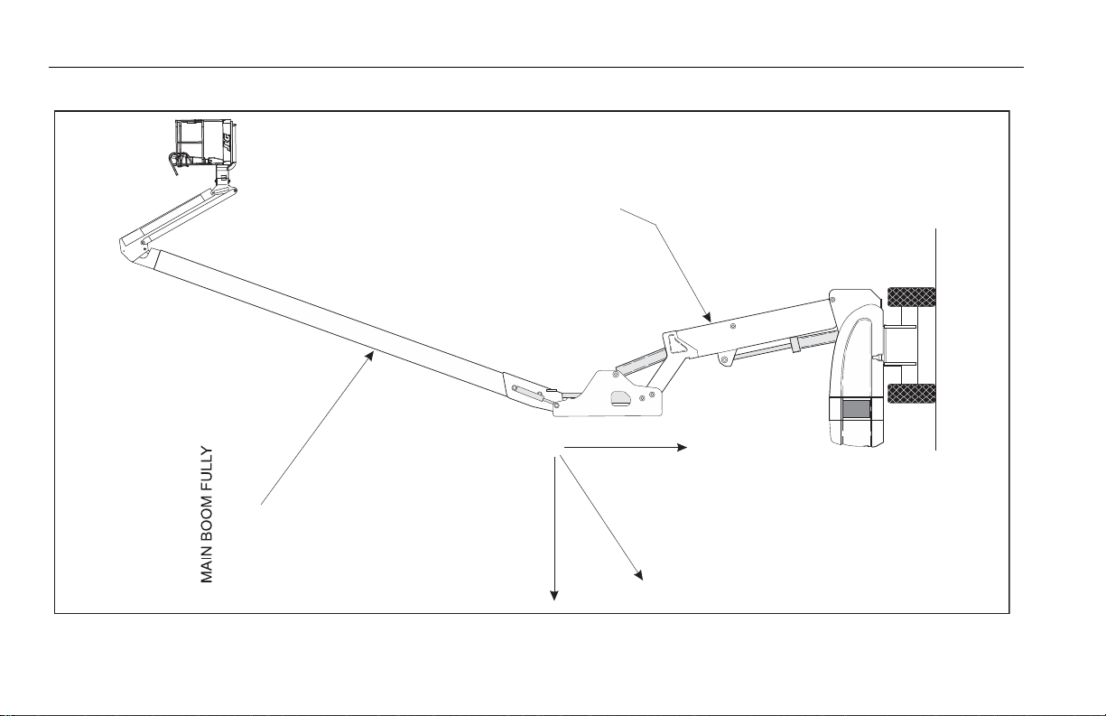
SECTION 4 - MACHINE OPERATION
EL EVATED AND
RET RA C TE D
TOWER BOOM FULLY
ELEVATED
MACHINE WILL UPSET
IN THIS DIRECTION IF
OPERATED ON AN
OUT-OF-LEVE L SURFACE
LEVEL SURFACE
Figure 4-3. Positions of Least Backward Stability (Sheet 2 of 2)
4-4 – JLG Lift – 3121654
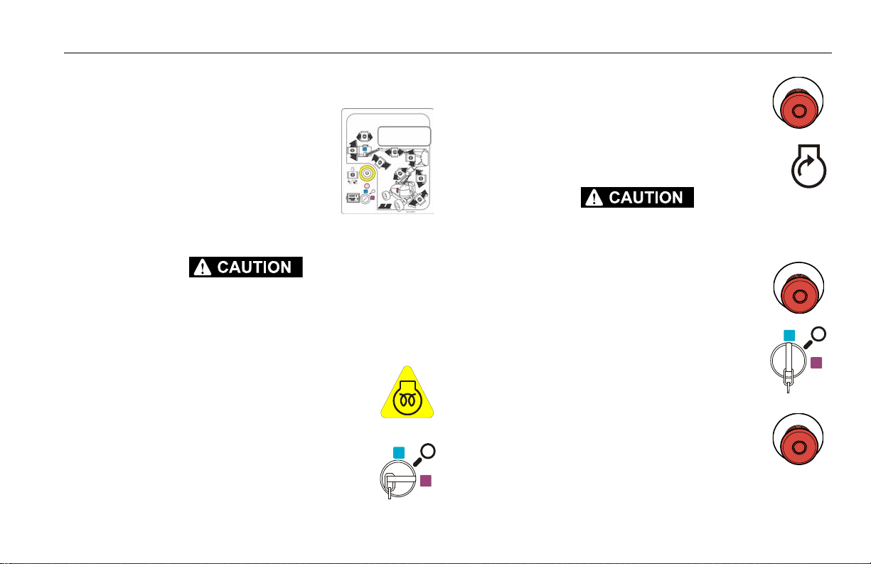
SECTION 4 - MACHINE OPERATION
4.3 ENGINE OPERATION
NOTE: Initial starting should always be per-
formed from the Ground Control station.
Starting Procedure
IF ENGINE FAILS TO START PROMPTLY, DO NOT CRANK FOR AN EXTENDED TIME.
SHOULD ENGINE FAIL TO START AGAIN, ALLOW STARTER TO “COOL OFF” FOR 2-3 MINUTES. IF ENGINE FAILS AFTER SEVERAL ATTEMPTS, REFER TO ENGINE MAINTENANCE
MANUAL.
NOTE: Diesel engines only: After turning on ignition,
operator must wait until glow plug indicator light
goes out before cranking engine.
1. Turn key of Platform/Ground Select switch to
Ground.
2. Pull the Power/Emergency Stop switch to On.
3. Push the Engine Start switch until engine starts.
ALLOW ENGINE TO WARM-UP FOR A FEW MINUTES AT LOW SPEED BEFORE APPLYING
ANY LOAD.
4. After engine has had sufficient time to warm
up, push in the Power/Emergency Stop switch
and shut engine off.
5. Turn Platform/Ground Select switch to Platform.
6. From Platform, pull Power/Emergency Stop
switch out.
3121654 – JLG Lift – 4-5
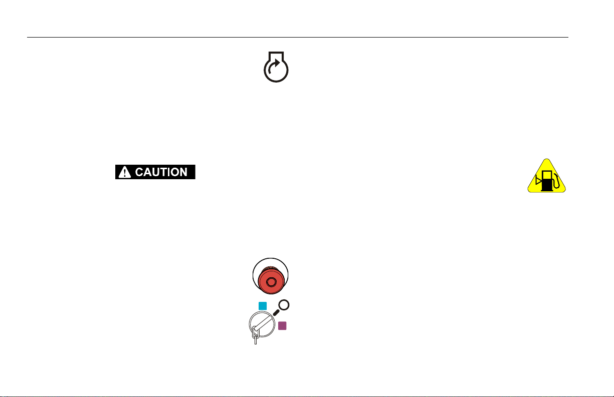
SECTION 4 - MACHINE OPERATION
7. Push the Engine Start switch until engine starts.
NOTE: Footswitch must be in released (up) position before starter will
operate. If starter operates with footswitch in the depressed position, DO NOT OPERATE MACHINE.
Shutdown Procedure
IF AN ENGINE MALFUNCTION CAUSES AN UNSCHEDULED SHUTDOWN, DETERMINE
THE CAUSE AND CORRECT IT BEFORE RESTARTING THE ENGINE.
1. Remove all load and allow engine to operate at low speed
for 3-5 minutes; this allows further reduction of internal
engine temperature.
2. Push Power/Emergency Stop switch in.
3. Turn Platform/Ground Select switch to Off.
Refer to Engine Manufacturer’s manual for detailed
information.
Fuel Reserve / Shut-Off System
NOTE: Reference the Service and Maintenance Manual along with a
qualified JLG Mechanic to verify your machine setup.
The Fuel Shutoff System monitors the fuel in the tank and senses
when the fuel level is getting low. The JLG Control System automatically shuts the engine down before the fuel tank is emptied
unless the machine is set up for Engine Restart.
If fuel level reaches the Empty range, the Low Fuel
light will begin to flash once a second and there will
be approximately 60 minutes of engine run time
left. If the system is in this condition and automatically shuts down the engine or if the operator manually shuts down the engine before the 60 minute run time is
complete, the Low Fuel light will flash 10 times a second and the
engine will react according to machine setup. Setup options are
as follows:
• Engine One Restart - When the engine shuts down, the
operator will be permitted to cycle power and restart the
engine once with approximately 2 minutes of run time.
After the 2 minute run time is complete or if the engine is
shut down by the operator prior to the completion of the 2
minute run time, it cannot be restarted until fuel is added
to the tank.
4-6 – JLG Lift – 3121654

SECTION 4 - MACHINE OPERATION
• Engine Restart - When the engine shuts down, the operator will be permitted to cycle power and restart the engine
for approximately 2 minutes of run time. After the 2 minutes of run time is complete, the operator may cycle power
and restart the engine for an additional 2 minutes of run
time. The operator can repeat this process until there is no
more fuel available.
CONTACT A QUALIFIED JLG MECHANIC IF THE MACHINE NEEDS RESTARTED AFTER NO
MORE FUEL IS AVAILABLE.
• Engine Stop - When the engine shuts down, no restarts
will be permitted until fuel is added to the tank.
4.4 TRAVELING (DRIVING)
See Figure 4-4., Grade and Sideslopes
NOTE: Refer to the Operating Specifications table for Gradeability and
Sideslope ratings.
All ratings for Gradeability and Sideslope are based upon the
machine’s boom being in the stowed position, fully lowered, and
retracted.
Traveling is limited by two factors:
1. Gradeability, which is the percent of grade of the incline the
machine can climb.
2. Sideslope, which is the angle of the slope the machine can
be driven across.
3121654 – JLG Lift – 4-7

SECTION 4 - MACHINE OPERATION
G
R
A
D
E
S
I
D
E
S
L
O
P
E
Figure 4-4. Grade and Sideslopes
4-8 – JLG Lift – 3121654

SECTION 4 - MACHINE OPERATION
Traveling Forward and Reverse
DO NOT DRIVE WITH BOOM ABOVE HORIZONTAL EXCEPT ON A SMOOTH, FIRM AND
LEVEL SURFACE.
TO AVOID LOSS OF TRAVEL CONTROL OR “TIP OVER”, DO NOT DRIVE MACHINE ON
GRADES EXCEEDING THOSE SPECIFIED ON THE SERIAL NUMBER PLATE.
BE SURE THE TURNTABLE LOCK IS ENGAGED BEFORE ANY EXTENDED TRAVELING.
DO NOT DRIVE ON SIDESLOPES WHICH EXCEED 5 DEGREES.
USE EXTREME CAUTION WHEN DRIVING IN REVERSE AND AT ALL TIMES WHEN THE
PLATFORM IS ELEVATED.
BEFORE DRIVING, MAKE SURE BOOM IS POSITIONED OVER REAR DRIVE AXLE. IF
BOOM IS OVER FRONT WHEELS, STEER AND DRIVE CONTROLS WILL BE REVERSED.
1. At Platform Controls, pull out Emergency Stop
switch and activate footswitch.
2. Position Drive controller to FORWARD or
REVERSE as desired.
This machine is equipped with a Drive Orientation Indicator. The
yellow light on the platform control console indicates that the
boom is swung beyond the rear drive tires and the machine may
Drive/Steer in the opposite direction from the movement of the
controls. If the indicator is illuminated, operate the Drive function
in the following manner:
3121654 – JLG Lift – 4-9

SECTION 4 - MACHINE OPERATION
1. Match the black and
white direction arrows
on both platform control panel and the chassis to determine the
direction the machine
will travel.
2. Push and release the Drive Orientation Override switch. Within 3 seconds, slowly move the
Drive control toward the arrow matching the
intended direction of machine travel. The indicator light will flash during the 3 second interval until the drive function is selected.
4.5 STEERING
Position thumb switch on Drive/Steer controller to
Right for steering right, or to Left for steering left.
4.6 PLATFORM
Platform Level Adjustment
ONLY USE THE PLATFORM LEVELING OVERRIDE FUNCTION FOR SLIGHT LEVELING OF
THE PLATFORM. INCORRECT USE COULD CAUSE THE LOAD/OCCUPANTS TO SHIFT OR
FALL. FAILURE TO DO SO COULD RESULT IN DEATH OR SERIOUS INJURY.
To Level Up or Down - Position the Platform/Level
control switch Up or Down and hold until the platform is level.
Platform Rotation
To rotate the platform to the left or right, use the
Platform Rotate control switch to select the direction and hold until desired position is reached.
4-10 – JLG Lift – 3121654

SECTION 4 - MACHINE OPERATION
4.7 BOOM
AN ORANGE TILT ALARM WARNING LIGHT, LOCATED ON THE CONTROL CONSOLE,
LIGHTS WHEN THE CHASSIS IS ON A SEVERE SLOPE. DO NOT SWING, EXTEND OR RAISE
MAIN BOOM ABOVE HORIZONTAL WHEN LIT.
DO NOT DEPEND ON TILT ALARM AS A LEVEL INDICATOR FOR THE CHASSIS. CHASSIS
MUST BE LEVEL BEFORE SWINGING, EXTENDING OR RAISING TOWER BOOM ABOVE
HORIZONTAL.
TO AVOID UPSET, IF ORANGE TILT AL ARM WARNING LIGH T LIGHTS WHEN MAIN BOO M
IS EXTENDED OR RAISED ABOVE HORIZONTAL, RETRACT AND LOWER PLATFORM TO
NEAR GROUND LEVEL. THEN REPOSITION MACHINE SO THAT CHASSIS IS LEVEL
BEFORE EXTENDING OR RAISING MAIN BOOM.
TRAVELING WITH MAIN BOOM RETRACTED AND BELOW HORIZONTAL IS PERMITTED
ON GRADES AND SIDE SLOPES SPECIFIED ON THE SERIAL NUMBER PLACARD.
TO AVOID SERIOUS INJURY, DO NOT OPERATE MACHINERY IF ANY CONTROL LEVERS
OR TOGGLE SWITCHES CONTROLLING PLATFORM MOVEMENT DO NOT RETURN TO THE
OFF OR NEUTRAL POSITION WHEN RELEASED.
TO AVOID A COLLISION AND INJURY IF PLATFORM DOES NOT STOP WHEN A CONTROL
SWITCH OR LEVER IS RELEASED, REMOVE FOOT FROM FOOTSWITCH OR USE EMERGENCY STOP TO STOP THE MACHINE.
Swinging the Boom
To swing boom, use Swing control switch to select
Right or Left direction.
WHEN SWINGING THE BOOM MAKE SURE THERE IS AMPLE ROOM FOR THE BOOM TO
CLEAR SURROUNDING WALLS, PARTITIONS AND EQUIPMENT.
NOTE: On CE Market machines, when boom functions are being oper-
ated there is an interlock that prevents the use of Drive and Steer
functions.
3121654 – JLG Lift – 4-11

SECTION 4 - MACHINE OPERATION
Raising and Lowering the Tower Boom
To raise or lower the Tower Boom, depress footswitch,
position Tower Lift controller Up or Down, and hold
until the desired height is reached.
DISCONTINUE OPERATION IF THE UPRIGHT IS OUT OF ALIGNMENT OR THE BOOM
MALFUNCTION LIGHT REMAINS ILLUMINATED.
IF THE UPRIGHT IS OUT OF ALIGNMENT WITH THE PLATFORM RAISED, LOWER THE
MAIN BOOM AND TELESCOPE OUT UNTIL THE PLATFORM REACHES THE GROUND. THE
TOWER BOOM DOWN FUNCTION IS CUT OUT IN THIS CONDITION. REPORT THE PROBLEM TO THE PROPER SERVICE PERSONNEL. DO NOT OPERATE THE MACHINE UNTIL
THE CONDITION IS CORRECTED.
Raising and Lowering the Main Boom
To raise or lower the Main Boom, position the Main
Boom Lift switch to Up or Down until the desired
height is reached.
Telescoping the Main Boom
To extend or retract the main boom, use the Main
Telescope Control Switch to select In or Out movement.
4.8 SHUT DOWN AND PARK
1. Drive machine to a protected area.
2. Assure boom is fully retracted and lowered over rear (Drive)
axle; all access panels and doors closed and secured.
3. Remove all load and allow engine to operate 3-5 minutes at
idle to permit reduction of engine internal temperatures.
4. At Ground Controls, turn Key Select switch to (center) Off
Position, Power/Emergency Stop switch (down) to Off.
Remove key.
5. Cover Platform Control console to protect instruction placards, warning decals and operating controls from hostile
environment.
4-12 – JLG Lift – 3121654

SECTION 4 - MACHINE OPERATION
4.9 LIFTING AND TIE DOWN
See Figure 4-5.
Lifting
1. Refer to the Serial Number Plate, refer to the Specifications
section of this manual, or weigh the individual unit to find
out the Gross Vehicle Weight.
2. Place the boom in the stowed position with the turntable
locked.
3. Remove all loose items from the machine.
4. Attach lifting device and equipment only to the designated
lifting points.
5. Properly adjust the rigging to prevent damage to the
machine and so the machine remains level.
Tie Down
WHEN TRANSPORTING THE MACHINE, THE BOOM MUST BE FULLY LOWERED INTO
THE BOOM REST.
1. Place the boom in the stowed position with the turntable
locked.
2. Remove all loose items from the machine.
3. Secure the chassis and the platform using straps or chains of
adequate strength and attached to the designated tie down
points.
3121654 – JLG Lift – 4-13
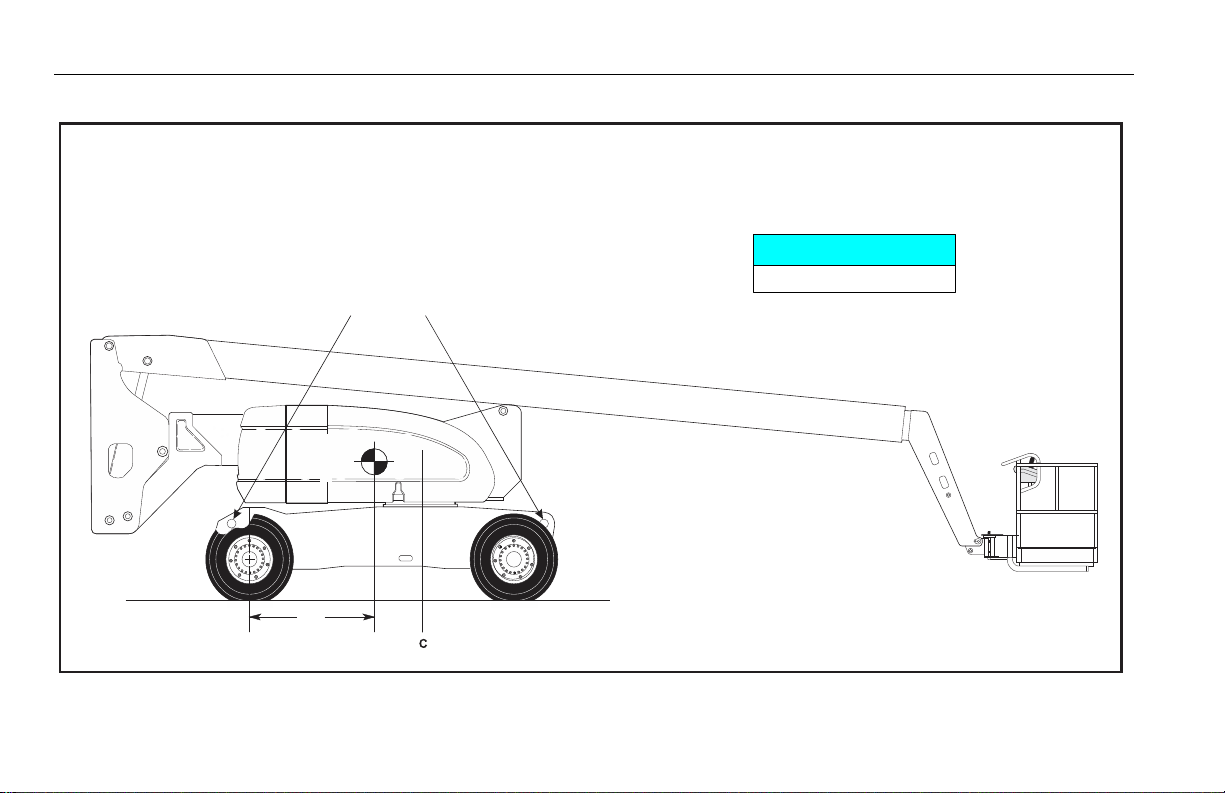
SECTION 4 - MACHINE OPERATION
L
ROTATION
CENTER
OF
GRAVITY
"A"
LIFT HERE
"A" Dimensio n
Steer A xl e T o C en ter O f Gr avi ty
52" (1320 mm)
(SPREADER BAR REQUIRED)
Figure 4-5. Lifting Chart
4-14 – JLG Lift – 3121654

SECTION 4 - MACHINE OPERATION
4.10 OSCILLATING AXLE LOCKOUT TEST (IF EQUIPPED)
LOCKOUT SYSTEM TEST MUST BE PERFORMED QUARTERLY, ANY TIME A SYSTEM COMPONENT IS REPLACED, OR WHEN IMPROPER SYSTEM OPERATION IS SUSPECTED.
Refer to Section 2.4, Oscillating Axle Lockout Test (If Equipped) for
procedure.
4.11 TOWING
The machine is not equipped with a tow package. Refer to Section 5 for emergency towing procedures.
4.12 TOW BAR (IF EQUIPPED)
RUNAWAY VEHICLE/MACHINE HAZARD. MACHINE HAS NO TOWING BRAKES. TOWING
VEHICLE MUST BE ABLE TO CONTROL MACHINE AT ALL TIMES. ON-HIGHWAY TOWING
NOT PERMITTED. FAILURE TO FOLLOW INSTRUCTIONS COULD CAUSE SERIOUS INJURY
OR DEATH.
MAXIMUM TOWING SPEED 5 M.P.H. (8 K.M.H.)
MAXIMUM TOWING GRADE 25%.
Prior to towing the machine, complete the following:
DO NOT TOW MACHINE WITH ENGINE OPERATING OR DRIVE HUBS ENGAGED.
1. Retract, lower and position boom in travel position; lock
turntable.
2. Lower tow bar and connect to towing vehicle
3. Disconnect drive hubs by inverting disconnect cap.
3121654 – JLG Lift – 4-15

SECTION 4 - MACHINE OPERATION
Figure 4-6. Tow Bar
4-16 – JLG Lift – 3121654

SECTION 4 - MACHINE OPERATION
4. Position steer/tow selector valve for towing; pull valve knob
out for towing. The machine is now in the towing mode.
After towing the machine, complete the following:
1. Actuate steer/tow selector valve for steering; push valve
knob in to the actuated position.
2. Reconnect drive hubs by inverting disconnect cap.
3. Disconnect tow bar from towing vehicle and place it in the
stowed position as shown in Figure 4-6. The machine is now
in the driving mode.
4.13 DUAL FUEL SYSTEM (GAS ENGINE ONLY)
Description
The dual fuel system enables the standard gasoline engine to run
on either gasoline or LP gas. The system includes pressurized cylinders mounted on the frame, and the valves and switches
needed to switch the fuel supply from gasoline to LP gas or from
LP gas to gasoline.
A two position, Fuel Select switch at the platform
control station supplies electrical power to open
the gasoline shut-off solenoid and close the LP gas
shut off solenoid when positioned to the Gasoline
position. This switch also allows electrical power to open the LP
gas shut-off solenoid and close the gasoline shut-off solenoid
when positioned to the LP position.
IT IS POSSIBLE TO SWITCH FROM ONE FUEL SOURCE TO THE OTHER WITHOUT STOPPING THE ENGINE. EXTREME CARE MUST BE TAKEN AND THE FOLLOWING INSTRUCTIONS MUST BE FOLLOWED.
3121654 – JLG Lift – 4-17
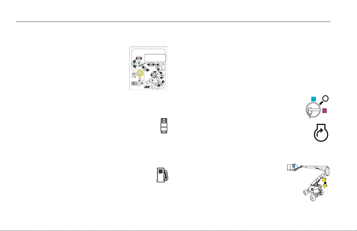
SECTION 4 - MACHINE OPERATION
Changing From Gasoline to LP Gas
1. Start engine from Ground Control
Console.
2. Open hand valve on LP gas supply tank by turning counterclockwise.
3. While the engine is operating, place the two position
LPG/Gasoline switch at the platform control station
to the "LP" position.
Changing From LP Gas to Gasoline
1. With engine operating on LP under a no-load condition, position FUEL SELECT switch at Platform
Control Station to GASOLINE position.
2. Close hand valve on LP gas supply tank by turning
clockwise.
4.14 RE-SYNCHRONIZE UPRIGHT
Releveling Valve
A pull type control valve allows the operator to adjust the upright
level cylinder if the upright is not 90° (vertical) relative to the
chassis (Refer to Figure 2.9 and Figure 2.10). This valve is located
in the tank compartment area.
Perform the following steps with the aid of an assistant:
1. Turn the key switch to the ground control
position.
2. Start the engine.
3. Pull and hold the red relevel knob located next to
the main control valve. Refer to Figure 4-7.
4. Raise the tower boom 6 feet (1.8 m).
5. Release the red relevel knob.
4-18 – JLG Lift – 3121654
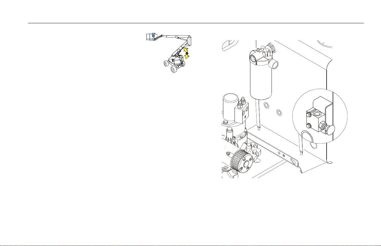
6. Lower the tower boom fully and con-
Figure 4-7. Releveling Valve
tinue to hold down the switch to
Tower Down for an additional 20 seconds.
7. Repeat steps 3 thru 6 as necessary until the upright is 90°
(vertical) relative to the chassis.
SECTION 4 - MACHINE OPERATION
3121654 – JLG Lift – 4-19

SECTION 4 - MACHINE OPERATION
4.15 AIR COMPRESSOR
Normal Startup Procedure
1. Check compressor oil level - top up if necessary.
2. Air service valve (beside the compressor) closed.
3. Start the engine.
4. Compressor switch (in the platform) ON - compressor should
activate.
5. Allow the compressor to warm up for several minutes before
operating.
Normal Shutdown Procedure
1. Close service valve and allow compressor to unload and cool
down (approx. 5 min.).
2. Position the compressor switch in the platform to OFF.
3. Shut down the engine.
Daily Operation
Before Starting:
1. Check compressor oil level.
2. Check for any leaks or loose bolts.
3. Check drive belt is tight.
After Starting:
1. Check pressure gauge for correct operating pressure.
2. Check for leaks.
4-20 – JLG Lift – 3121654
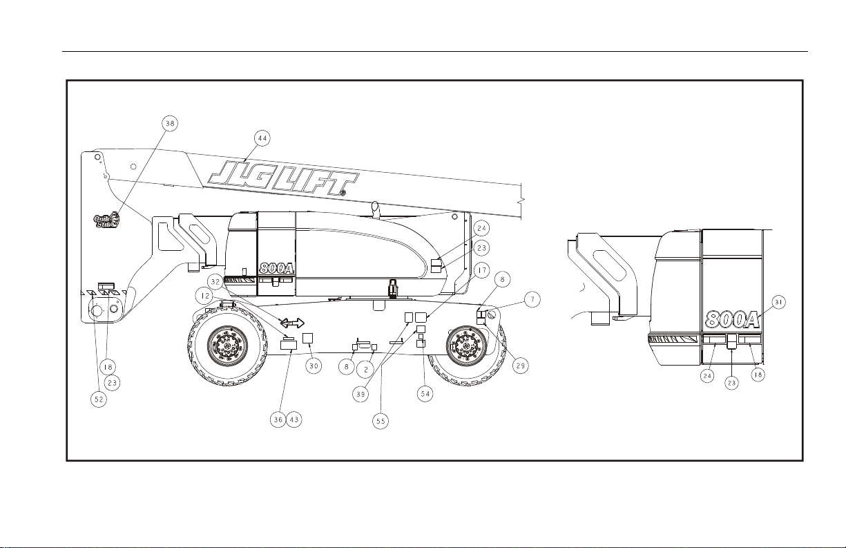
SECTION 4 - MACHINE OPERATION
Figure 4-8. Decal Installation - Sheet 1 of 5
3121654 – JLG Lift – 4-21
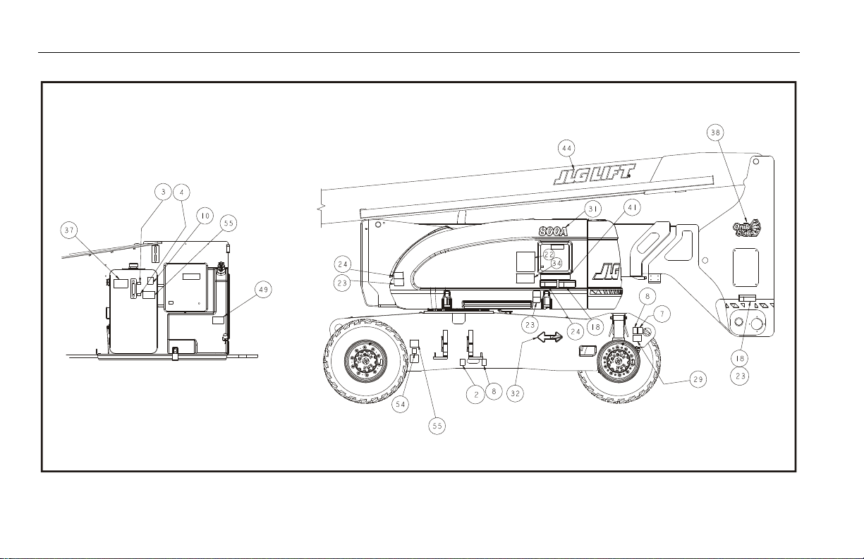
SECTION 4 - MACHINE OPERATION
Figure 4-9. Decal Installation - Sheet 2 of 5
4-22 – JLG Lift – 3121654
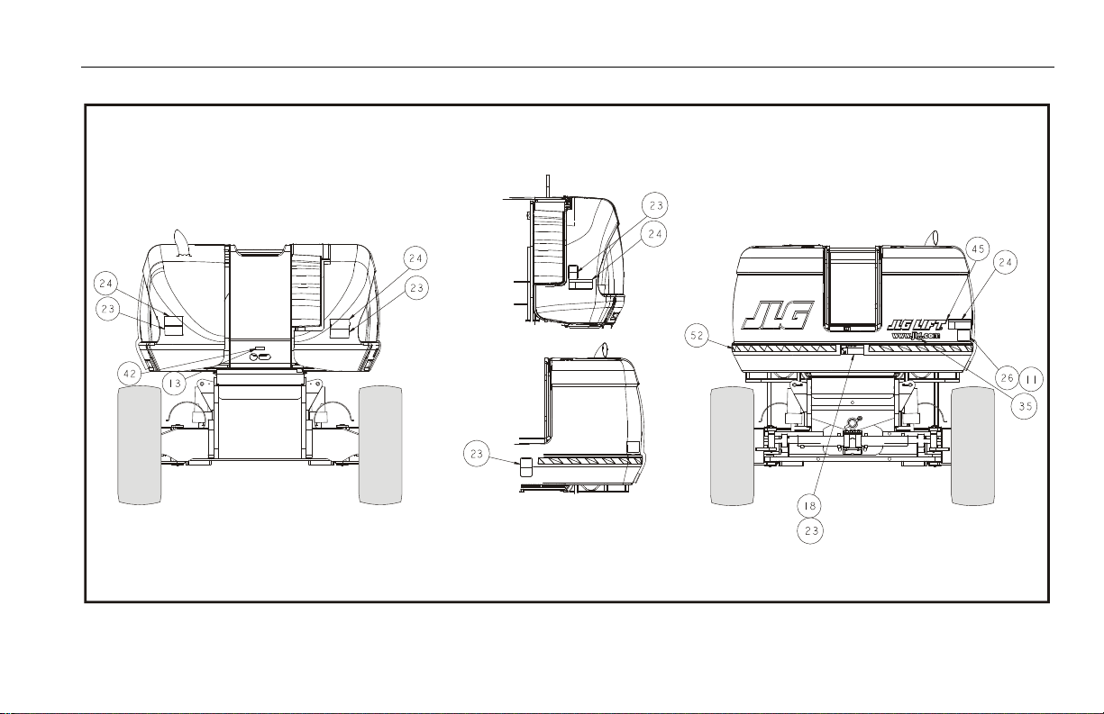
SECTION 4 - MACHINE OPERATION
Figure 4-10. Decal Installation - Sheet 3 of 5
3121654 – JLG Lift – 4-23

SECTION 4 - MACHINE OPERATION
Figure 4-11. Decal Installation - Sheet 4 of 5
4-24 – JLG Lift – 3121654

SECTION 4 - MACHINE OPERATION
Figure 4-12. Decal Installation - Sheet 5 of 5
3121654 – JLG Lift – 4-25

SECTION 4 - MACHINE OPERATION
Table 4-1. Decal Legend
Item # ANSI
0274483-C
1- -- -- - - -
2 1701499 1701499 1701499 1701499
3- -- -- - - -
4- -- -- - - -
5 1701509 1701509 1701509 1701509
6- -- -- - - -
7 1703811 1703811 1703811 1703811
8 1703814 1703814 1703814 1703814
9 1704277 1704277 1704277 1704277
10 1704412 1704412 1704412 1704412
11 - - - - 1705084 1705084
12 - - 1705514 - - - -
13- -- -- - - -
14- -- -- - - -
15 1705337 - - - - - -
16- -- -- - - -
17- -- -- - - -
18 1703953 1703942 - - - -
French
0274488-CCE0274484-5
Aus
1001114464-C
Table 4-1. Decal Legend
Item # ANSI
0274483-C
19- -- -- - - -
20 1702868 1704000 - - - -
21 1703797 1703924 1705921 1705921
22 1705336 1705347 1705822 1705822
23 1703804 1703948 1701518 1701518
24 1703805 1703936 1705961 1705961
25 3252347 1703984 1705828 1705828
26- -- -- - - -
27- -- -- - - -
28- -- -- - - -
29 1703477 1703477 1703960 1703960
30 1702631 1702631 1702631 1702631
31 1705007 1705007 1705007 1705007
32 1701501 1701501 1701501 1701501
33 1001121801 1001121803 1705978 1705978
34 1001121814 1001121816 1705978 1705978
35- -- -- - - -
36 1706948 1706948 - - - -
French
0274488-CCE0274484-5
Aus
1001114464-C
4-26 – JLG Lift – 3121654

SECTION 4 - MACHINE OPERATION
Table 4-1. Decal Legend
Item # ANSI
0274483-C
37 1001096141 1705977 1705977 1705977
38 1703959 1001131269 1703959 1703959
39 1001131269 1700584 - - 1001131269
40 1001108495 1001108495 - - - -
41 1001095809 1001095809 - - - -
42- -- -- - - -
43- -- -- - - -
44- -- -- - - -
45- -- -- - - -
46- -- -- - - -
47- -- -- - - -
48- -- -- - - -
49 1701505 1701505 1701505 1701505
50- -- -- - - -
51- -- -- - - -
52- -- -- - - -
53- -- -- - - -
54- -- -- - - -
French
0274488-CCE0274484-5
Aus
1001114464-C
Table 4-1. Decal Legend
Item # ANSI
0274483-C
55- -- -- - - -
56 1705351 1705429 - - - -
57 - - - - - - 1001112551
French
0274488-CCE0274484-5
Aus
1001114464-C
3121654 – JLG Lift – 4-27

SECTION 4 - MACHINE OPERATION
NOTES:
4-28 – JLG Lift – 3121654

5.1 GENERAL
SECTION 5 - EMERGENCY PROCEDURES
SECTION 5. EMERGENCY PROCEDURES
This section explains the steps to be taken in case of an emergency situation while operating.
5.2 INCIDENT NOTIFICATION
JLG Industries, Inc. must be notified immediately of any incident
involving a JLG product. Even if no injury or property damage is
evident, the factory should be contacted by telephone and provided with all necessary details.
In USA:
JLG Phone: 877-JLG-SAFE (554-7233)
Outside USA:
240-420-2661
E-mail:
ProductSafety@JLG.com
Failure to notify the manufacturer of an incident involving a JLG
Industries product within 48 hours of such an occurrence may
void any warranty consideration on that particular machine.
FOLLOWING ANY ACCIDENT, THOROUGHLY INSPECT THE MACHINE AND TEST ALL
FUNCTIONS FIRST FROM THE GROUND CONTROLS, THEN FROM THE PLATFORM CONTROLS. DO NOT LIFT ABOVE 3 M (10 FT.) UNTIL YOU ARE SURE THAT ALL DAMAGE HAS
BEEN REPAIRED, IF REQUIRED, AND THAT ALL CONTROLS ARE OPERATING CORRECTLY.
5.3 EMERGENCY OPERATION
Operator Unable to Control Machine
IF THE PLATFORM OPERATOR IS PINNED, TRAPPED OR UNABLE TO
OPERATE OR CONTROL MACHINE:
1. Other personnel should operate the machine from ground
controls only as required.
2. Other qualified personnel on the platform may use the platform controls. DO NOT CONTINUE OPERATION IF CONTROLS
DO NOT FUNCTION PROPERLY.
3. Cranes, forklift trucks or other equipment can be used to
remove platform occupants and stabilize motion of the
machine.
3121654 – JLG Lift – 5-1

SECTION 5 - EMERGENCY PROCEDURES
Platform or Boom Caught Overhead
If the platform or boom becomes jammed or snagged in overhead structures or equipment, rescue platform occupants prior to
freeing the machine.
Boom Movement Prevented By Boom Control System
Lowering the boom onto an object or structure, with the boom at
high angles, may cause the boom control system to prevent
movement of the machine. This can include movement necessary
to lift the boom off the object. Movement of the boom can be
regained by observing the following:
1. Shut off the engine.
2. Rescue platform occupants prior to freeing machine.
3. Use cranes, forklifts or other equipment to stabilize motion
of the machine as required.
4. From the ground control position, use the Auxiliary Power
System to carefully raise the boom off the object.
5. Once clear, restart the engine and return the platform to the
ground.
6. Inspect the machine for damage before continued use of the
machine.
5.4 EMERGENCY TOWING PROCEDURES
Towing this machine is prohibited, unless properly equipped.
However, provisions for moving the machine have been incorporated. For specific procedures, refer to Section 4.
5-2 – JLG Lift – 3121654

SECTION 6 - GENERAL SPECIFICATIONS & OPERATOR MAINTENANCE
SECTION 6. GENERAL SPECIFICATIONS & OPERATOR MAINTENANCE
6.1 INTRODUCTION
This section of the manual provides additional necessary information to the operator for proper operation and maintenance of
this machine.
The maintenance portion of this section is intended as information to assist the machine operator to perform daily maintenance
tasks only, and does not replace the more thorough Preventive
Maintenance and Inspection Schedule included in the Service
and Maintenance Manual.
Other Publications Available:
Service and Maintenance Manual .............................................3121651
Illustrated Parts Manual - Global................................................3121652
6.2 OPERATING SPECIFICATIONS
Table 6-1. Operating Specifications
Maximum Work Load (Capacit y)
AN S I Un re s tr i c te d :
CE / AU S Un r es t ri c te d :
Maximum Travel Grade with boom in stowed position
(Gradeability) 4WD Figure 4-4.
Maximum Travel Grade
(Side Slope)Figure 4-4.
Maximum Vertical Platform Height: 74 ft. (22.5 m)
Maximum Horizontal Platform Reach 51 ft. 10 in. (15.8 m)
Ground Clearance 12 in. (30 cm)
Wheelbase 10 ft. (3.05 m)
Maximum Tire Load: 17,755 lbs. (8060 kg)
Maximum Drive Speed: 3.0 mph (4.8 kph)
Maximum Hyd. Operating Pressure 4500 psi (310 Bar)
Electrical System Voltage 12 volts
Jet Blast Rating 90 mph (145 kph)
with boom in stowed position
500 lb (227 kg)
500 lb (230 kg)
5° ANSI
3° CE/AUS
45%
3121654 – JLG Lift – 6-1

SECTION 6 - GENERAL SPECIFICATIONS & OPERATOR MAINTENANCE
Table 6-1. Operating Specifications
Max. Ground Bearing Pressure
Gross Machine Weight 36,200 lb. (16,420 kg)
84 psi (5.3 kg/cm
Dimensional Data
Table 6-2. Dimensional Data
Turning Radius (Outside) 14 ft.- 6 in. (4.42 m)
Turning Radius (Inside) 11 ft.- 0 in. (2.13 m)
Boom Elevation
Ab o ve G ra d e
B el o w G r ad e
Machine Height Stowed 9 ft. 9.5 in.(2.98 m)
Machine Length (Stowed) 36 ft.-6 in. (11.13 m)
Machine Width 8 ft.-0 in. (2.44 m)
Wheelbase 10 ft.- 0 in. (3.05 m)
+80 ft.-3 in. (24.46 m)
-13 ft.- 1 in. (3.99 m)
3
)
Capacities
Table 6-3. Capacities
Fuel Tank Approx. 39 gallons (147.6 liters)
Hydraulic Tank Approx. 40 gallons (151.4 liters)
Hydraulic System (Including Tank) 77 Gal. (291.4 L)
Drive Hub 44 ounces (1.3 L)
Drive Brake 2.7 ounces (80 ml)
Engine Crankcase
D eu t z D 2 01 1 L0 4
D eu t z T D 2. 9 L
GM
Air Compressor 4 qts. (3.8 L)
11 quarts (10.5 L)
2.4 Gallon (8.9 L) w/Filter
4.5 qts. (4.25 L) w/Filter
6-2 – JLG Lift – 3121654

SECTION 6 - GENERAL SPECIFICATIONS & OPERATOR MAINTENANCE
Engine Data
Type Liquid Cooled (Oil)
Fuel Diesel
Oil Capacity
Co o li n g S y st em
Cr a nk c as e
Tot a l C a pa c it y
Idle RPM 1000
Low RPM 1800
High RPM 2600
Alternator 55 Amp, belt drive
Fuel Consumption 0.88 GPH (3.33 lph)
Battery 1000 Cold Cranking Amps, 210 minutes
Horsepower 61.6 @ 2600 RPM, full load
Table 6-4. Deutz D2011L04 Specifications
5 Quarts (4.5 L)
11 Quarts (10.5 L) w/Filter
16 Quarts (15 L)
Reserve Capacity, 12 VDC
Table 6-5. Deutz TD 2.9 Specifications
Fuel Ultra Low Sulfur Diesel (15 ppm)
Output 67 hp (50 kW)
Torque 173 ft.lbs. (234 Nm) @ 1800rpm
Oi l Ca p ac i t y ( Cr a nk c as e ) 2. 4 Ga l lo n ( 8. 9 L) w /F i lt e r
Cooling System 3.3 Gallon (12.5 L)
Low RPM 1200 ±50 rpm
High RPM 2600±50 rpm
Alternator 95 Amp
Fuel Consumption 0.65 GPH (2.48 lph)
3121654 – JLG Lift – 6-3

SECTION 6 - GENERAL SPECIFICATIONS & OPERATOR MAINTENANCE
Table 6-6. GM 3.0L
Fuel Gasoline or Gasoline/LP Gas
No. of Cylinders 4
BHP
G as o li n e
LP
Bore 4.0 in. (101.6 mm)
Stroke 3.6 in. (91.44 mm)
Displacement 181 cu.in. (3.0 L, 2966 cc)
Oil Capacity w/filter 4.5 qts. (4.25 L)
Minimum Oil Pressure
at i dl e
Ho t
Compression Ratio 9.2:1
Firing Order 1-3-4-2
Max. RPM 2800
83 hp @ 3000 rpm
75 hp @ 3000 rpm
6 psi (0.4 Bar) @ 1000 rpm
18 psi (1.2 Bar) @ 2000 rpm
Tires
Table 6-7. Tire Specifications
Size Type Ply Rating
15-625 pneumatic 16 H 95PSI
15-625 foam-filled 16 H N/A
18-625 foam-filled 16 H N/A
Load
Range
Pressure
(6.5 Bar)
6-4 – JLG Lift – 3121654
 Loading...