


 Loading...
Illustrated Parts Manual
Model
45HA
P/N
3120824
March 15, 2012
REVISION LOG
December 1993 - Original Issue Of Manual
March 1995 - Change 1 July 1997 - Revised
March 15, 2001 - Revised (Edited 0010415 to Revision 19) August 18, 2005 - Revised
June 10, 2009 - Revised
March 15, 2012 - Revised
3120824 |
A |
REVISION LOG
B |
3120824 |
TABLE OF CONTENTS
FIGURE NO. |
TITLE |
PAGE NO. |
SECTION 1 - FRAME |
|
|
1-1 Frame & Steering Installation - 5’-9”/1.75M 2WD Frame (Single Rod Cylinder) . . . . . . . . . . . . . 1-2 1-2 Frame & Steering Installation - 6’-6”/2M 2WD Frame (Double Rod Cylinder) . . . . . . . . . . . . . . . 1-6 1-3 Frame & Steering Installation - 6’-6”/2M 4WD Frame . . . . . . . . . . . . . . . . . . . . . . . . . . . . . . . . . 1-10 1-4 Tire and Wheel Drive Installations . . . . . . . . . . . . . . . . . . . . . . . . . . . . . . . . . . . . . . . . . . . . . . . 1-14 1-5 Drive Hub Assembly . . . . . . . . . . . . . . . . . . . . . . . . . . . . . . . . . . . . . . . . . . . . . . . . . . . . . . . . . . 1-20 1-6 Drive Hub/Brake Assembly . . . . . . . . . . . . . . . . . . . . . . . . . . . . . . . . . . . . . . . . . . . . . . . . . . . . . 1-26 1-7 Drive Brake Assembly - Ausco . . . . . . . . . . . . . . . . . . . . . . . . . . . . . . . . . . . . . . . . . . . . . . . . . . 1-32 1-8 Drive Brake Assembly - Mico . . . . . . . . . . . . . . . . . . . . . . . . . . . . . . . . . . . . . . . . . . . . . . . . . . . 1-34 1-9 Drive Motor Assembly - 2WD. . . . . . . . . . . . . . . . . . . . . . . . . . . . . . . . . . . . . . . . . . . . . . . . . . . . 1-38 1-10 Drive Motor Assembly - 4WD. . . . . . . . . . . . . . . . . . . . . . . . . . . . . . . . . . . . . . . . . . . . . . . . . . . . 1-42 1-11 Valves Installations (Frame Mounted) . . . . . . . . . . . . . . . . . . . . . . . . . . . . . . . . . . . . . . . . . . . . . 1-46 1-12 Tow Package Installation . . . . . . . . . . . . . . . . . . . . . . . . . . . . . . . . . . . . . . . . . . . . . . . . . . . . . . . 1-48
SECTION |
2 - TURNTABLE |
|
2-1 |
Control Valves Installations - Vickers Valves (Ford Gas & Deutz Diesel) . . . . . . . . . . . . . . . . . . |
2-2 |
2-2 |
Control Valves Installations - Vickers Valves (Electric Machines) . . . . . . . . . . . . . . . . . . . . . . . . |
2-6 |
2-3 |
Accessory Valve Assembly . . . . . . . . . . . . . . . . . . . . . . . . . . . . . . . . . . . . . . . . . . . . . . . . . . . . |
2-10 |
2-4 |
Valve Assembly - FPS (Steer) . . . . . . . . . . . . . . . . . . . . . . . . . . . . . . . . . . . . . . . . . . . . . . . . . . . |
2-12 |
2-5 |
Control Valve Assembly (Vickers) (Prior to October 1994) . . . . . . . . . . . . . . . . . . . . . . . . . . . . . |
2-14 |
2-6 |
Control Valve Assembly (Vickers) (October 1994 to Present) . . . . . . . . . . . . . . . . . . . . . . . . . . |
2-18 |
2-7 |
Valve Assembly - Single Stack Racine . . . . . . . . . . . . . . . . . . . . . . . . . . . . . . . . . . . . . . . . . . . . |
2-22 |
2-8 |
Valve Assembly - FPS . . . . . . . . . . . . . . . . . . . . . . . . . . . . . . . . . . . . . . . . . . . . . . . . . . . . . . . . |
2-24 |
2-9 |
Turntable, Bearing and Swing Drive Installation . . . . . . . . . . . . . . . . . . . . . . . . . . . . . . . . . . . . . |
2-26 |
2-10 |
Swing Brake Assembly . . . . . . . . . . . . . . . . . . . . . . . . . . . . . . . . . . . . . . . . . . . . . . . . . . . . . . . . |
2-30 |
2-11 |
Swing Motor Assembly . . . . . . . . . . . . . . . . . . . . . . . . . . . . . . . . . . . . . . . . . . . . . . . . . . . . . . . . |
2-32 |
2-12 |
Ford Engine Installation (With DIS) . . . . . . . . . . . . . . . . . . . . . . . . . . . . . . . . . . . . . . . . . . . . . . . |
2-34 |
2-13 |
Dual Fuel Installation (Ford with DIS) . . . . . . . . . . . . . . . . . . . . . . . . . . . . . . . . . . . . . . . . . . . . . |
2-44 |
2-14 |
Generator Installation - 110V (Ford Machines) (Optional) . . . . . . . . . . . . . . . . . . . . . . . . . . . . . |
2-46 |
2-15 |
Deutz Engine Installation . . . . . . . . . . . . . . . . . . . . . . . . . . . . . . . . . . . . . . . . . . . . . . . . . . . . . . . |
2-54 |
2-16 |
Generator Installation - 110V (Deutz Machines) (Optional) . . . . . . . . . . . . . . . . . . . . . . . . . . . . . |
2-58 |
2-17 |
Pump Assembly - Barnes (Ford & Deutz Powered Machines) . . . . . . . . . . . . . . . . . . . . . . . . . . |
2-62 |
2-18 |
Electric Powered Machines Components Installation . . . . . . . . . . . . . . . . . . . . . . . . . . . . . . . . . |
2-64 |
2-19 |
Pump Assembly - Barnes (Electric Powered Machines) . . . . . . . . . . . . . . . . . . . . . . . . . . . . . . . |
2-70 |
2-20 |
Battery Charger Assembly (Electric Powered Machines) . . . . . . . . . . . . . . . . . . . . . . . . . . . . . . |
2-72 |
2-21 |
Tank Installation . . . . . . . . . . . . . . . . . . . . . . . . . . . . . . . . . . . . . . . . . . . . . . . . . . . . . . . . . . . . . . |
2-74 |
2-22 |
Rotary Oil Coupling Installation . . . . . . . . . . . . . . . . . . . . . . . . . . . . . . . . . . . . . . . . . . . . . . . . . . |
2-80 |
2-23 |
Optional Manual Descent Installation . . . . . . . . . . . . . . . . . . . . . . . . . . . . . . . . . . . . . . . . . . . . . |
2-82 |
2-24 |
Ground Control Box Installation (Gas/Diesel Machines) . . . . . . . . . . . . . . . . . . . . . . . . . . . . . . . |
2-84 |
2-25 |
Ground Control Box Installation (Electric Machines) . . . . . . . . . . . . . . . . . . . . . . . . . . . . . . . . . . |
2-88 |
2-26 |
Tilt Indicator, Light & Alarms Installation (Turntable Mounted). . . . . . . . . . . . . . . . . . . . . . . . . . . |
2-92 |
2-27 |
Hoods Installation (Gas/Diesel Machines Built Through 1992) . . . . . . . . . . . . . . . . . . . . . . . . . . |
2-96 |
2-28 |
Hoods Installation (Gas/Diesel Machines Built 1993 to Present). . . . . . . . . . . . . . . . . . . . . . . . . |
2-98 |
2-29 |
Hoods Installation (Electric Machines). . . . . . . . . . . . . . . . . . . . . . . . . . . . . . . . . . . . . . . . . . . . . |
2-102 |
3120824 |
i |
TABLE OF CONTENTS (Continued)
FIGURE NO. |
TITLE |
PAGE NO. |
SECTION 3 - BOOM |
|
|
3-1 Booms And Limit Switches Installation . . . . . . . . . . . . . . . . . . . . . . . . . . . . . . . . . . . . . . . . . . . . 3-2
3-2 Main Boom Assembly . . . . . . . . . . . . . . . . . . . . . . . . . . . . . . . . . . . . . . . . . . . . . . . . . . . . . . . . 3-6
3-3 Tower Boom Assemblies . . . . . . . . . . . . . . . . . . . . . . . . . . . . . . . . . . . . . . . . . . . . . . . . . . . . . . . 3-10
3-4 Boom Wipers Installation . . . . . . . . . . . . . . . . . . . . . . . . . . . . . . . . . . . . . . . . . . . . . . . . . . . . . . 3-14
SECTION |
4 - PLATFORMS |
|
4-1 |
Standard Platform and Footswitch Installations. . . . . . . . . . . . . . . . . . . . . . . . . . . . . . . . . . . . . . |
4-2 |
4-2 |
Low Mount Platform and Footswitch Installations . . . . . . . . . . . . . . . . . . . . . . . . . . . . . . . . . . . . |
4-6 |
4-3 |
Rotator Motor Assembly . . . . . . . . . . . . . . . . . . . . . . . . . . . . . . . . . . . . . . . . . . . . . . . . . . . . . . . |
4-10 |
4-4 |
Console Box Assembly (Electric Machines) . . . . . . . . . . . . . . . . . . . . . . . . . . . . . . . . . . . . . . . . |
4-12 |
4-5 |
Console Box Assembly (Gas, Diesel & Dual Fuel Machines Prior to January 1993) . . . . . . . . . |
4-16 |
4-6 |
Console Box Assembly (Gas, Diesel & Dual Fuel Machines January 1993 to Present) . . . . . . |
4-20 |
4-7 |
Optional Common Platform Mounted Components. . . . . . . . . . . . . . . . . . . . . . . . . . . . . . . . . . . |
4-24 |
SECTION |
5 - CYLINDERS |
|
5-1 |
Axle Lockout Cylinder Assembly . . . . . . . . . . . . . . . . . . . . . . . . . . . . . . . . . . . . . . . . . . . . . . . . . |
5-2 |
5-2 |
Level Cylinder Assembly (Tower Boom) . . . . . . . . . . . . . . . . . . . . . . . . . . . . . . . . . . . . . . . . . . . |
5-4 |
5-3 |
Lift Cylinder Assembly (Main Boom) . . . . . . . . . . . . . . . . . . . . . . . . . . . . . . . . . . . . . . . . . . . . . . |
5-6 |
5-4 |
Lift Cylinder Assembly (Tower Boom) . . . . . . . . . . . . . . . . . . . . . . . . . . . . . . . . . . . . . . . . . . . . . |
5-8 |
5-5 |
Platform Level Cylinder Assembly (Main Boom) (Prior to October 1992). . . . . . . . . . . . . . . . . . |
5-10 |
5-6 |
Platform Level Cylinder Assembly (Main Boom) (October 1992 to Present). . . . . . . . . . . . . . . . |
5-12 |
5-7 |
Steer Cylinder Assembly (2WD Double Acting Rod). . . . . . . . . . . . . . . . . . . . . . . . . . . . . . . . . . |
5-14 |
5-8 |
Steer Cylinder Assembly (2WD Single Acting Rod) . . . . . . . . . . . . . . . . . . . . . . . . . . . . . . . . . . |
5-16 |
5-9 |
Steer Cylinder Assembly (4WD) . . . . . . . . . . . . . . . . . . . . . . . . . . . . . . . . . . . . . . . . . . . . . . . . . |
5-18 |
5-10 |
Telescope Cylinder Assembly (Main Boom) . . . . . . . . . . . . . . . . . . . . . . . . . . . . . . . . . . . . . . . . |
5-20 |
5-11 |
Telescope Cylinder Assembly (Tower Boom) . . . . . . . . . . . . . . . . . . . . . . . . . . . . . . . . . . . . . . . |
5-22 |
5-12 |
Cylinder Bellows Installation (Optional) . . . . . . . . . . . . . . . . . . . . . . . . . . . . . . . . . . . . . . . . . . . . |
5-24 |
SECTION |
6 - HYDRAULICS |
|
6-1 |
Axle Lockout Without Swivel Hydraulic Diagram . . . . . . . . . . . . . . . . . . . . . . . . . . . . . . . . . . . . |
6-2 |
6-2 |
Drive Hydraulic Diagram (2WD With Swivel) . . . . . . . . . . . . . . . . . . . . . . . . . . . . . . . . . . . . . . . |
6-4 |
6-3 |
Drive Hydraulic Diagram (4WD With Swivel). . . . . . . . . . . . . . . . . . . . . . . . . . . . . . . . . . . . . . . . |
6-8 |
6-4 |
Lift & Level (Tower Boom) Hydraulic Diagram . . . . . . . . . . . . . . . . . . . . . . . . . . . . . . . . . . . . . . . |
6-8 |
6-5 |
Lift & Slave (Main Boom) Hydraulic Diagram . . . . . . . . . . . . . . . . . . . . . . . . . . . . . . . . . . . . . . . |
6-14 |
6-6 |
Pump Hydraulic Diagram (Gas & Diesel Machines) . . . . . . . . . . . . . . . . . . . . . . . . . . . . . . . . . . |
6-16 |
6-7 |
Pump Hydraulic Diagram (Electric Machines) . . . . . . . . . . . . . . . . . . . . . . . . . . . . . . . . . . . . . . |
6-20 |
6-8 |
Rotation Hydraulic Diagram . . . . . . . . . . . . . . . . . . . . . . . . . . . . . . . . . . . . . . . . . . . . . . . . . . . . |
6-24 |
6-9 |
Steer With Swivel Hydraulic Diagram . . . . . . . . . . . . . . . . . . . . . . . . . . . . . . . . . . . . . . . . . . . . . |
6-26 |
6-10 |
Swing Hydraulic Diagram . . . . . . . . . . . . . . . . . . . . . . . . . . . . . . . . . . . . . . . . . . . . . . . . . . . . . |
6-28 |
6-11 |
Telescope (Main Boom) Hydraulic Diagram . . . . . . . . . . . . . . . . . . . . . . . . . . . . . . . . . . . . . . . |
6-30 |
6-12 |
Telescope (Tower Boom) Hydraulic Diagram (Ford Gas & Deutz Diesel) . . . . . . . . . . . . . . . . . . |
6-32 |
6-13 |
Telescope (Tower Boom) Hydraulic Diagram (Electric Machines) . . . . . . . . . . . . . . . . . . . . . . . . |
6-34 |
6-14 |
Hydraulic Diagram List . . . . . . . . . . . . . . . . . . . . . . . . . . . . . . . . . . . . . . . . . . . . . . . . . . . . . . . . |
6-36 |
ii |
3120824 |
TABLE OF CONTENTS
FIGURE NO. |
TITLE |
PAGE NO. |
|
SECTION |
7 |
- ELECTRICAL |
|
7-1 |
Electrical Diagram List . . . . . . . . . . . . . . . . . . . . . . . . . . . . . . . . . . . . . . . . . . . . . . . . . . . . . . . . . |
7-2 |
|
7-2 |
Electrical Schematic . . . . . . . . . . . . . . . . . . . . . . . . . . . . . . . . . . . . . . . . . . . . . . . . . . . . . . . . . . |
7-6 |
|
SECTION |
8 |
- DECALS |
|
8-1 |
Decals Installation . . . . . . . . . . . . . . . . . . . . . . . . . . . . . . . . . . . . . . . . . . . . . . . . . . . . . . . . . . . . |
8-2 |
|
SECTION 9 |
- RECOMMENDED SERVICE PARTS STOCK . . . . . . . . . . . . . . . . . . . . . . |
. . 9-1 |
|
SECTION |
10 - SPECIAL OPTIONS . . . . . . . . . . . . . . . . . . . . . . . . . . . . . . . . . . . . . . . . . |
.10-1 |
|
3120824 |
iii |
TABLE OF CONTENTS (Continued)
FIGURE NO. |
TITLE |
PAGE NO. |
iv |
3120824 |
|
SECTION 1 FRAME |
|
|
|
|
|
|
|
S |
|
|
|
|
|
|
|
|
|
|
|
|
E |
|
|
TABLE OF CONTENTS |
|
|
|
|
|
|
|
|
C |
|
FIGURE |
DESCRIPTION |
PAGE |
|
T |
|
|
|
|
|||
|
|
|
|
I |
|
1-1 |
Frame & Steering Installation - 5’-9”/1.75M 2WD Frame (Single Rod Cylinder) |
1-2 |
|
|
|
|
|
|
|||
1-2 |
Frame & Steering Installation - 6’-6”/2M 2WD Frame (Double Rod Cylinder) . . . . . . . . . . . |
. 1-6. . |
|
O |
|
1-3 |
Frame & Steering Installation - 6’-6”/2M 4WD Frame . . . . . . . . . . . . . . . . . . . . . . . . . . . . . |
. 1-10. . |
|
|
|
1-4 |
Tire and Wheel Drive Installations . . . . . . . . . . . . . . . . . . . . . . . . . . . . . . . . . . . . . . . . . . . . |
. 1-14. . |
|
N |
|
1-5 |
Drive Hub Assembly . . . . . . . . . . . . . . . . . . . . . . . . . . . . . . . . . . . . . . . . . . . . . . . . . . . . . . . |
. 1-20. . |
|
|
|
1-6 |
Drive Hub/Brake Assembly . . . . . . . . . . . . . . . . . . . . . . . . . . . . . . . . . . . . . . . . . . . . . . . . . |
. 1-26. . |
|
1 |
|
1-7 |
Drive Brake Assembly - Ausco . . . . . . . . . . . . . . . . . . . . . . . . . . . . . . . . . . . . . . . . . . . . . . . |
. 1-32. . |
|
|
|
1-8 |
Drive Brake Assembly - Mico . . . . . . . . . . . . . . . . . . . . . . . . . . . . . . . . . . . . . . . . . . . . . . . . |
. 1-34. . |
|
|
|
1-9 |
Drive Motor Assembly - 2WD . . . . . . . . . . . . . . . . . . . . . . . . . . . . . . . . . . . . . . . . . . . . . . . . |
. 1-38. . |
|
F |
|
1-10 |
Drive Motor Assembly - 4WD . . . . . . . . . . . . . . . . . . . . . . . . . . . . . . . . . . . . . . . . . . . . . . . . |
. 1-42. . |
|
|
|
1-11 |
Valves Installations (Frame Mounted) . . . . . . . . . . . . . . . . . . . . . . . . . . . . . . . . . . . . . . . . . . |
. 1-46. . |
|
R |
|
1-12 |
Tow Package Installation |
1-48 |
|
A |
|
|
|
|
|||
|
|
|
|
M |
|
|
|
|
|
E |
|
|
|
|
|
|
|
|
|
|
|
|
|
3120824 |
1-1 |

S E C T I O N
1
F
R A M E
SECTION 1 FRAME
FIGURE 1-1. FRAME AND STEERING INSTALLATION - 5’-9”/1.75m 2WD FRAME (WITH SINGLE ROD CYLINDER)
1-2 |
3120824 |
SECTION 1 FRAME
FIGURE 1-1. FRAME AND STEERING INSTALLATION - 5’-9”/1.75M 2WD FRAME (WITH SINGLE ROD CYLINDER)
FIG & ITEM # |
PART NUMBER |
DESCRIPTION |
QTY. |
REV. |
||||
|
|
|
|
|
|
|
||
|
|
|
|
FRAME OPTIONS |
Ref. |
|
||
|
|
2360288 |
|
Fixed Axle (Standard Stability/Standard Platform) |
1 |
|
|
|
|
|
2360283 |
|
Oscillating Axle (Standard Stability/Standard Platform |
1 |
|
|
|
|
|
2360322 |
|
Fixed Axle (2 to 1 Stability/Low Mount Platform) |
1 |
|
|
|
|
|
2360321 |
|
Oscillating Axle (2 to 1 Stability/Low Mount Platform) |
1 |
|
|
|
|
|
0251326 |
|
OSCILLATING AXLE INSTALLATION (OPTIONAL) |
Ref. |
B |
||
1 |
|
Not Used |
|
|
|
|
|
|
2 |
|
4843094 |
|
Axle Weldment |
1 |
|
|
|
3 |
|
Not Used |
|
|
|
|
|
|
4 |
|
2160002 |
|
Fitting, Grease |
1 |
|
|
|
5 |
|
4842621 |
|
Pin, Pivot |
1 |
|
|
|
6 |
|
3311601 |
|
Nut 3/8”-16NC |
1 |
|
|
|
7 |
|
4761600 |
|
Lockwasher 3/8” |
1 |
|
|
|
8 |
|
4751600 |
|
Flatwasher 3/8” |
1 |
|
|
|
9 |
|
4300034 |
|
Stud (Welded on Part) |
1 |
|
|
|
10 |
|
1682406 |
|
Lockout Cylinder Assembly (See Section 5 for |
2 |
|
|
|
|
|
|
|
Breakdown) |
|
|
|
|
11 |
|
4842622 |
|
Pin (Top) |
2 |
|
|
|
12 |
|
4842794 |
|
Pin (Bottom) |
2 |
|
|
|
13 |
|
0641406 |
|
Bolt 1/4”-20NC x 3/4” |
4 |
|
|
|
14 |
|
4761400 |
|
Lockwasher 1/4” |
4 |
|
|
|
|
|
4751400 |
|
Flatwasher 1/4” |
4 |
|
|
|
|
|
0239197 |
|
STEERING INSTALLATION |
Ref. |
E |
||
101 |
|
4130207 |
|
Spindle - Right Side |
1 |
|
|
|
|
|
0960839 |
|
Bushing, Bronze |
2 |
|
|
|
102 |
|
4130210 |
|
Spindle - Left Side |
1 |
|
|
|
|
|
0960839 |
|
Bushing, Bronze |
2 |
|
|
|
103 |
|
2780153 |
|
Hub, Wheel (Includes Item 107) |
2 |
|
|
|
104 |
|
2160002 |
|
Fitting, Grease |
3 |
|
|
|
105 |
|
1682020 |
|
Steer Cylinder Assembly (See Section 5 for |
1 |
|
|
|
|
|
|
|
Breakdown) |
|
|
|
|
106 |
|
3840962 |
|
Tie-Rod |
1 |
|
|
|
107 |
|
0630137 |
|
Stud, Wheel (Part of Item 103) |
18 |
|
|
|
108 |
|
3300012 |
|
Nut, Wheel |
18 |
|
|
|
109 |
|
0721003 |
|
Bolt #10-24NC x 3/8” |
6 |
|
|
|
110 |
|
4761000 |
|
Lockwasher #10 |
6 |
|
|
|
111 |
|
1120019 |
|
Cap, Hub |
2 |
|
|
|
112 |
|
3450608 |
|
Pin, Cotter 3/16” x 2" |
2 |
|
|
|
113 |
|
3322603 |
|
Nut, Slotted 1"-12NF |
|
2 |
|
|
|
|
|
|
|
||||
114 |
|
4740001 |
|
Washer, Hardened |
|
2 |
|
|
115 |
|
0440112 |
|
Cup, Bearing |
|
2 |
|
|
116 |
|
0440113 |
|
Cone, Bearing |
|
2 |
|
|
117 |
|
3960373 |
|
Seal, Oil |
|
2 |
|
|
|
|
|
|
|
|
|
|
|
S E C T I O N
1
F
R A M E
3120824 |
1-3 |

S E C T I O N
1
F
R A M E
SECTION 1 FRAME
FIGURE 1-1. FRAME AND STEERING INSTALLATION - 5’-9”/1.75M 2WD FRAME (WITH SINGLE ROD CYLINDER) (CONTINUED)
FIG & ITEM # |
PART NUMBER |
DESCRIPTION |
QTY. |
REV. |
|
|
|
|
|
118 |
3323003 |
Nut, Slotted 1 1/4”-12NF |
2 |
|
119 |
3450609 |
Pin, Cotter 3/16” x 2 1/4” |
2 |
|
120 |
3421340 |
Kingpin |
2 |
|
121 |
0440162 |
Washer, Thrust |
2 |
|
122 |
3431622 |
Pin, Clevis |
1 |
|
123 |
3450608 |
Pin, Cotter 3/16” x 2" |
1 |
|
124 |
4712600 |
Flatwasher 1" |
1 |
|
125 |
0440091 |
Washer, Thrust |
3 |
|
126 |
0642628 |
Bolt 1"-8NC x 3 1/2” |
2 |
|
127 |
0560805 |
Block, Tie-Rod (Right Side) |
1 |
|
128 |
3312602 |
Nut, Jam 1"-8NC |
2 |
|
129 |
3300175 |
Locknut |
1 |
|
130 |
0560804 |
Block, Tie-Rod (Left Side) |
1 |
|
131 |
3300229 |
Nut, Jam (Left Hand Thread) |
1 |
|
132 |
3323002 |
Nut, Jam 1 1/4”-12NF |
1 |
|
133 |
2160003 |
Fitting, Grease - 45° |
2 |
|
|
|
|
|
|
1-4 |
3120824 |

SECTION 1 FRAME
FIGURE 1-1. FRAME AND STEERING INSTALLATION - 5’-9”/1.75M 2WD FRAME (WITH SINGLE ROD CYLINDER) (CONTINUED)
FIG & ITEM # |
PART NUMBER |
DESCRIPTION |
QTY. |
REV. |
|
|
|
|
|
|
|
|
|
|
S E C T I O N
1
F
R A M E
3120824 |
1-5 |
S E C T I O N
1
F
R A M E
SECTION 1 FRAME
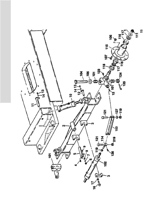
FIGURE 1-2. FRAME AND STEERING INSTALLATION - 6’-6”/2m 2WD FRAME (WITH DOUBLE ROD CYLINDER)
1-6 |
3120824 |

SECTION 1 FRAME
FIGURE 1-2. FRAME AND STEERING INSTALLATION - 6’-6”/2M 2WD FRAME (WITH DOUBLE ROD CYLINDER)
FIG & ITEM # |
PART NUMBER |
DESCRIPTION |
QTY. |
REV. |
|
|
|
|
|
|
|
FRAME OPTIONS |
Ref. |
|
|
2360262 |
Fixed Axle |
|
|
|
2360274 |
Oscillating Axle |
|
|
|
0251327 |
OSCILLATING AXLE INSTALLATION (OPTIONAL) |
Ref. |
— |
1 |
Not Used |
|
|
|
2 |
4842982 |
Axle Weldment |
1 |
|
3 |
0238390 |
Mounting Block Assembly - Steer Cylinder |
2 |
|
4 |
2160002 |
Fitting, Grease |
1 |
|
5 |
4842621 |
Pin, Pivot (Axle) |
1 |
|
6 |
3311601 |
Nut 3/8”-16NC |
1 |
|
7 |
4761600 |
Lockwasher 3/8” |
1 |
|
8 |
4751600 |
Flatwasher 3/8” |
1 |
|
9 |
4300034 |
Stud (Welded on Part) |
1 |
|
10 |
1682406 |
Lockout Cylinder Assembly (See Section 5 for |
2 |
|
|
|
Breakdown) |
|
|
11 |
4842622 |
Pin (Top) (Lockout Cylinder) |
2 |
|
12 |
4842794 |
Pin (Bottom) (Lockout Cylinder) |
2 |
|
13 |
0641406 |
Bolt 1/4”-20NC x 3/4” |
4 |
|
14 |
4761400 |
Lockwasher 1/4” |
4 |
|
|
0238395 |
STEERING INSTALLATION |
Ref. |
7 |
101 |
4130197 |
Spindle |
2 |
|
|
0960839 |
Bushing, Bronze |
2 |
|
102 |
|
Steer Cylinder Assembly Options (See Section 5 for |
1 |
|
|
|
Breakdown) |
|
|
|
1681814 |
Prior to S/N 31941 |
|
|
|
1683511 |
S/N 31941 to Present |
|
|
103 |
4842860 |
Tie-Rod |
2 |
|
104 |
3421340 |
Kingpin |
2 |
|
105 |
0440162 |
Washer, Thrust |
2 |
|
106 |
3300012 |
Nut, Wheel 1/2”-20NF |
18 |
|
107 |
0630137 |
Bolt, Wheel (Part of Item 115) |
18 |
|
108 |
0721004 |
Bolt #10-24 x 1/2” |
6 |
|
109 |
4761000 |
Lockwasher #10 |
6 |
|
110 |
1120019 |
Cap, Hub |
2 |
|
111 |
3322603 |
Nut, Slotted 1"-12NF |
2 |
|
112 |
3450608 |
Pin, Cotter 3/16” x 2" |
2 |
|
113 |
4740001 |
Washer, Hardened |
2 |
|
114 |
4842624 |
Block, Tie-Rod |
2 |
|
115 |
2780153 |
Hub, Wheel |
|
|
116 |
0440112 |
Cup, Bearing |
4 |
|
117 |
0440113 |
Cone, Bearing |
4 |
|
118 |
3960373 |
Seal, Oil |
2 |
|
119 |
3312205 |
Locknut 3/4”-10NC |
6 |
|
120 |
Not Used |
|
|
|
|
|
|
|
|
S E C T I O N
1
F
R A M E
3120824 |
1-7 |

S E C T I O N
1
F
R A M E
SECTION 1 FRAME
FIGURE 1-2. FRAME AND STEERING INSTALLATION - 6’-6”/2M 2WD FRAME (WITH DOUBLE ROD CYLINDER) (CONTINUED)
FIG & ITEM # |
PART NUMBER |
DESCRIPTION |
QTY. |
REV. |
|
|
|
|
|
121 |
0642224 |
Bolt 3/4”-10NC x 3" |
4 |
|
122 |
Not Used |
|
|
|
123 |
2160002 |
Fitting, Grease - Straight |
2 |
|
124 |
3323003 |
Nut, Slotted 1 1/4”-12NF |
2 |
|
125 |
3450609 |
Pin, Cotter 3/16” x 2 1/4” |
2 |
|
126 |
2160001 |
Fitting, Grease - 90° |
4 |
|
127 |
4740156 |
Washer, Thrust |
2 |
|
|
|
|
|
|
1-8 |
3120824 |

SECTION 1 FRAME
FIGURE 1-2. FRAME AND STEERING INSTALLATION - 6’-6”/2M 2WD FRAME (WITH DOUBLE ROD CYLINDER) (CONTINUED)
FIG & ITEM # |
PART NUMBER |
DESCRIPTION |
QTY. |
REV. |
|
|
|
|
|
|
|
|
|
|
S E C T I O N
1
F
R A M E
3120824 |
1-9 |
|
SECTION 1 FRAME |
S |
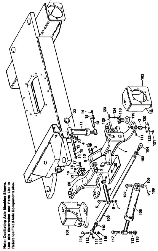
FIGURE 1-3. FRAME AND STEERING INSTALLATION 6’-6”/2m 4WD FRAME |
E |
|
C |
|
T |
|
I |
|
O |
|
N |
|
1 |
|
F |
|
R |
|
A |
|
M |
|
E |
|
|
|
1-10 |
3120824 |

SECTION 1 FRAME
FIGURE 1-3. FRAME AND STEERING INSTALLATION 6’-6”/2M 4WD FRAME
FIG & ITEM # |
PART NUMBER |
DESCRIPTION |
QTY. |
REV. |
|
|
|
|
|
|
|
FRAME OPTIONS |
Ref. |
|
|
2360277 |
Fixed Axle (Machines with 8.75" and 9.5" Tires) |
1 |
|
|
2360392 |
Fixed Axle (Machines with 12" Tires) |
1 |
|
|
2360272 |
Oscillating Axle (Machines with 8.75" and 9.5" Tires) |
1 |
|
|
2360393 |
Oscillating Axle (Machines with 12" Tires) |
1 |
|
|
0251976 |
OSCILLATING AXLE INSTALLATION (OPTIONAL) |
Ref. |
3 |
1 |
4842930 |
Axle Weldment |
1 |
|
2 |
0961003 |
Bushing, Bronze (Axle Pivot) |
2 |
|
3 |
0961029 |
Bushing, Bronze (Steer Pivot) |
4 |
|
4 |
4740158 |
Washer, Thrust |
2 |
|
5 |
0641630 |
Bolt 3/8”-16NC x 3 3/4” |
1 |
|
6 |
4751600 |
Flatwasher 3/8” |
1 |
|
7 |
3311605 |
Locknut 3/8”-16NC |
1 |
|
8 |
3421500 |
Pin, Pivot (Axle) |
1 |
|
9 |
Not Used |
|
|
|
10 |
2160002 |
Fitting, Grease - Straight |
1 |
|
11 |
1682406 |
Lockout Cylinder Assembly (See Section 5 for |
2 |
|
|
|
Breakdown) |
|
|
12 |
4842622 |
Pin, Attach (Top) (Lockout Cylinder) |
2 |
|
13 |
4842794 |
Pin, Attach (Bottom) (Lockout Cylinder) |
2 |
|
14 |
0641406 |
Bolt 1/4”-20NC x 3/4” |
4 |
|
15 |
4761400 |
Lockwasher 1/4” |
4 |
|
|
4751400 |
Flatwasher 1/4” |
4 |
|
16 |
4220115 |
Stop, Axle |
2 |
|
17 |
3311801 |
Nut 1/2”-13NC |
4 |
|
18 |
4761800 |
Lockwasher 1/2” |
4 |
|
19 |
4751800 |
Flatwasher 1/2” |
4 |
|
20 |
4300045 |
Stud (Welded on Part) |
4 |
|
21 |
4070690 |
Shim |
A/R |
|
22 |
0961127 |
Bushing, Snap |
2 |
|
23 |
4712600 |
Flatwasher |
A/R |
|
|
0238637 |
STEERING INSTALLATION |
Ref. |
E |
101 |
4130192 |
Spindle (Right Side) |
1 |
|
102 |
4130190 |
Spindle (Left Side) |
1 |
|
103 |
3300229 |
Nut, Jam (Left Hand Thread) |
1 |
|
104 |
0560714 |
Block, Tie-Rod (Left Side) |
1 |
|
105 |
3840861 |
Tie-Rod |
1 |
|
106 |
1681892 |
Steer Cylinder Assy (See Section 5 for Breakdown) |
1 |
|
107 |
3431622 |
Pin, Clevis |
1 |
|
108 |
4712600 |
Flatwasher 1" Narrow |
1 |
|
109 |
3450606 |
Pin, Cotter 3/16” x 1 1/2” |
1 |
|
110 |
3323002 |
Nut, Jam 1 1/4”-12NF |
1 |
|
111 |
2160002 |
Fitting, Grease |
6 |
|
112 |
0560605 |
Block, Tie-Rod (Right Side) |
1 |
|
113 |
0440091 |
Washer, Thrust |
3 |
|
|
|
|
|
|
S E C T I O N
1
F
R A M E
3120824 |
1-11 |

S E C T I O N
1
F
R A M E
SECTION 1 FRAME
FIGURE 1-3. FRAME AND STEERING INSTALLATION 6’-6”/2M 4WD FRAME (CONTINUED)
FIG & ITEM # |
PART NUMBER |
DESCRIPTION |
QTY. |
REV. |
|
|
|
|
|
114 |
0642628 |
Bolt 1"-8NC x 3 1/2” |
2 |
|
115 |
3312602 |
Nut, Jam 1"-8NC |
3 |
|
116 |
Not Used |
|
|
|
117 |
0630369 |
Bolt, Special |
1 |
|
118 |
3421190 |
Kingpin |
4 |
|
119 |
0440161 |
Bearing, Thrust |
2 |
|
120 |
|
Plate, Cover Options: |
4 |
|
|
3530244 |
Prior to August 1992 |
|
|
|
3536410 |
August 1992 to Present |
|
|
121 |
0641404 |
Bolt 1/4”-20NC x 1/2” (Prior to August 1992) |
8 |
|
|
4300106 |
Drivescrew (August 1992 to Present) |
8 |
|
122 |
4761400 |
Lockwasher 1/4” (Prior to August 1992 Only) |
8 |
|
123 |
0630083 |
Bolt, Special |
8 |
|
124 |
4761600 |
Lockwasher 3/8” |
8 |
|
125 |
Not Used |
|
|
|
126 |
4920096 |
Wire, Safety |
4 ft./20cm |
|
|
|
— — — — — — — — — — |
|
|
|
0100011 |
Loctite #242 |
A/R |
|
|
|
|
|
|
1-12 |
3120824 |
|
|
SECTION 1 FRAME |
|
|
|
S |
|
FIGURE 1-3. FRAME AND STEERING INSTALLATION 6’-6”/2M 4WD FRAME (CONTINUED) |
|
||||||
|
|
|
|
|
|
E |
|
FIG & ITEM # |
PART NUMBER |
DESCRIPTION |
QTY. |
REV. |
|
|
|
|
|
|
|
|
|
C |
|
|
|
|
|
|
|
|
|
|
|
|
|
|
|
T |
|
|
|
|
|
|
|
I |
|
|
|
|
|
|
|
O |
|
|
|
|
|
|
|
N |
|
|
|
|
|
|
|
1 |
|
|
|
|
|
|
|
F |
|
|
|
|
|
|
|
R |
|
|
|
|
|
|
|
A |
|
|
|
|
|
|
|
M |
|
|
|
|
|
|
|
E |
|
|
|
|
|
|
|
|
|
|
|
|
|
|
|
|
|
3120824 |
1-13 |
|
SECTION 1 FRAME |
S |
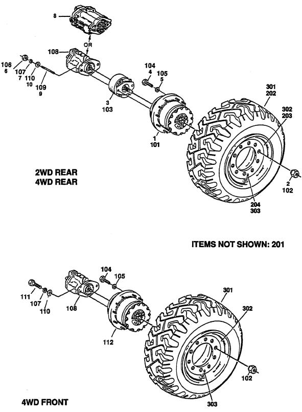
FIGURE 1-4. TIRE AND WHEEL DRIVE INSTALLATIONS |
E |
|
C |
|
T |
|
I |
|
O |
|
N |
|
1 |
|
F |
|
R |
|
A |
|
M |
|
E |
|
|
|
1-14 |
3120824 |

SECTION 1 FRAME
FIGURE 1-4. TIRE AND WHEEL DRIVE INSTALLATIONS
FIG & ITEM # |
PART NUMBER |
DESCRIPTION |
QTY. |
REV. |
|
|
|
|
|
|
|
WHEEL DRIVE INSTALLATIONS (2WD) |
Ref. |
|
|
0238521 |
Gas/Diesel Machines Built Prior to October 1992 & |
Ref. |
C |
|
|
All Electric Machines Built to Present |
|
|
|
0253630 |
Gas/Diesel Machines Built October 1992 to Present |
Ref. |
— |
|
|
(Standard) |
|
|
|
0270217 |
Gas/Diesel Machines (Post Production Alternative) |
Ref. |
1 |
|
|
(Standard) |
|
|
|
0256126 |
Gas/Diesel Machines Built October 1992 to Present |
Ref. |
— |
|
|
(15% Maximum Gradability) |
|
|
|
0250218 |
Gas/Diesel Machines (Post Production Alternative) |
Ref. |
1 |
|
|
(15% Maximum Gradability) |
|
|
1 |
|
Drive Hub Assembly Options (See Figure 1-5 for |
2 |
|
|
|
Breakdown): |
|
|
|
|
Electric Machines: |
|
|
|
2780134 |
Prior to March 1989 (W1B1 Stamped on ID |
|
|
|
See Note |
Plate) |
|
|
|
|
Note: When replacing complete hub recommend |
|
|
|
|
using 2780168 Hub Assembly. |
|
|
|
2780168 |
March 1989 to Present (W1BF Stamped on ID |
|
|
|
|
Plate) |
|
|
|
|
Gas/Diesel Machines: |
|
|
|
2780134 |
Prior to March 1989 (W1B1 Stamped on ID |
|
|
|
See Note |
Plate) |
|
|
|
|
Note: When replacing complete hub recommend |
|
|
|
|
using 2780168 Hub Assembly. |
|
|
|
2780168 |
March 1989 to October 1992 (W1BF Stamped |
|
|
|
|
on ID Plate) |
|
|
|
2780169 |
October 1992 to Present (Standard) |
|
|
|
2780167 |
October 1992 to Present (15% Max Gradability) |
|
|
2 |
3300012 |
Nut, Wheel |
18 |
|
3 |
|
Drive Brake Assembly Options: |
2 |
|
|
0920072 |
Prior to January 1992 (Ausco) (See Figure 1-7 for |
|
|
|
|
Breakdown) |
|
|
|
0920084 |
January 1992 to S/N 33476 (Mico) (See Figure 1-8 |
|
|
|
|
for Breakdown) |
|
|
|
0920110 |
S/N 33476 to Present (Mico) (See Figure 1-8 for |
|
|
|
|
Breakdown) |
|
|
|
0920119 |
Optional Brake (Mico) (May be used as alternative) |
|
|
|
|
(was p/n 0920117) |
|
|
|
7018612 |
Repair Kit - 0920117/0920119 Brake (Includes |
1 |
|
|
|
Case Seal, Piston Inner & Outer O-Rings & |
|
|
|
|
Back-up Rings, Stator Disc, Rotor Disc, Return |
|
|
|
|
Plate, Springs, Oil Seal, Bearing, 2 Retaining |
|
|
|
|
Rings & 2 Mounting Face Gaskets) (1 Per |
|
|
|
|
Assembly) |
|
|
|
7000731 |
Gasket, Mounting Face |
2 |
|
4 |
0642016 |
Bolt 5/8”-11NC x 2" |
12 |
|
5 |
4762000 |
Lockwasher 5/8” |
12 |
|
6 |
3311801 |
Nut 1/2”-13NC |
4 |
|
7 |
4761800 |
Lockwasher 1/2” |
4 |
|
|
|
|
|
|
S E C T I O N
1
F
R A M E
3120824 |
1-15 |

S E C T I O N
1
F
R A M E
SECTION 1 FRAME
FIGURE 1-4. TIRE AND WHEEL DRIVE INSTALLATIONS (CONTINUED)
FIG & ITEM # |
PART NUMBER |
DESCRIPTION |
QTY. |
REV. |
|
|
|
|
|
8 |
Use 1001096405 |
Drive Motor Assembly (See Figure 1-9 for |
2 |
|
|
|
Breakdown) (was p/n 3160132) |
|
|
9 |
4300092 |
Stud 1/2” x 5 1/2” |
4 |
|
10 |
4751800 |
Flatwasher 1/2” |
4 |
|
|
0250432 |
WHEEL DRIVE INSTALLATION (4WD) (REAR DRIVE |
Ref. |
C |
|
|
HAS SEPARATE HUB AND BRAKE) |
|
|
|
0270158 |
WHEEL DRIVE INSTALLATION (4WD) (POST |
Ref. |
1 |
|
|
PRODUCTION ALTERNATIVE) |
|
|
101 |
|
Drive Hub Assembly - Rear Options (See Figure 1-5 for |
2 |
|
|
|
Breakdown): |
|
|
|
2780175 |
September 1989 to November 1992 |
|
|
|
2780167 |
November 1992 to Present |
|
|
102 |
3300012 |
Nut, Wheel |
36 |
|
103 |
|
Drive Brake Assembly Options: |
2 |
|
|
0920072 |
September 1989 to January 1992 (Ausco) (See |
|
|
|
|
Figure 1-7 for Breakdown) |
|
|
|
0920084 |
January 1992 to S/N 33476 (Mico) (See Figure 1-8 |
|
|
|
|
for Breakdown) |
|
|
|
0920110 |
S/N 33476 to Present (Mico) (See Figure 1-8 for |
|
|
|
|
Breakdown) |
|
|
|
0920119 |
Optional Brake (Mico) (May be used as alternative) |
|
|
|
|
(was p/n 0920117) |
|
|
|
7018612 |
Repair Kit - 0920117/0920119 Brake (Includes |
1 |
|
|
|
Case Seal, Piston Inner & Outer O-Rings & Back- |
|
|
|
|
up Rings, Stator Disc, Rotor Disc, Return Plate, |
|
|
|
|
Springs, Oil Seal, Bearing, 2 Retaining Rings & 2 |
|
|
|
|
Mounting Face Gaskets) (1 Per Assembly) |
|
|
|
7000731 |
Gasket, Mounting Face |
2 |
|
104 |
0642014 |
Bolt 5/8”-11NC x 2" |
24 |
|
105 |
4762000 |
Lockwasher 5/8” |
24 |
|
106 |
3311801 |
Nut 1/2”-13NC |
4 |
|
107 |
4761800 |
Lockwasher 1/2” |
8 |
|
108 |
3160130 |
Drive Motor Assembly (See Figure 1-10 for Breakdown) |
4 |
|
109 |
4300092 |
Stud 1/2”-13NC x 5 1/2” |
4 |
|
110 |
4751800 |
Flatwasher 1/2” |
8 |
|
111 |
0641810 |
Bolt 1/2”-13NC x 1 1/4” |
4 |
|
112 |
|
Drive Hub/Brake Assembly - Front Options (See Figure |
2 |
|
|
|
1-6 for Breakdown) |
|
|
|
2780150 |
September 1989 to August 1992 |
|
|
|
2780193 |
August 1992 to November 1992 |
|
|
|
2780191 |
November 1992 to Present |
|
|
|
|
TIRE AND WHEEL OPTIONS (2WD) |
Ref. |
|
201 |
|
Tire and Wheel Options (2WD Front) (Not Shown) |
A/R |
|
|
0239396 |
Tire and Wheel Assembly - Pneumatic - 9.50" x 16.5" |
2 |
|
|
4520110 |
Tire - 9.50" x 16.5" (General Jumbo GLT) |
2 |
|
|
Use 0253131 |
Tire and Wheel Assembly - Foam Filled 8.75" x |
2 |
|
|
|
16.5"LT (Goodyear Unisteel) (Prior to S/N 31086) |
|
|
|
|
|
|
|
1-16 |
3120824 |
|
|
SECTION 1 FRAME |
|
|
|
S |
|
FIGURE 1-4. TIRE AND WHEEL DRIVE INSTALLATIONS (CONTINUED) |
|
|
|
|
|||
|
|
|
|
|
|
E |
|
FIG & ITEM # |
PART NUMBER |
DESCRIPTION |
QTY. |
REV. |
|
|
|
|
|
|
|
|
|
C |
|
201 (cont’d) |
0253131 |
Tire and Wheel Assembly - Foam-Filled 8.75" x 16.5" |
2 |
|
|
|
|
|
|
LT (Galaxy) (S/N 31086 to Present) |
|
|
|
T |
|
|
0239806 |
Tire and Wheel Assembly - Foam-Filled 9.5" x 16.5" |
2 |
|
|
|
|
|
|
(General) |
|
|
|
I |
|
|
|
|
|
|
|
|
|
|
|
Note: Assemblies may require ballast/foam filling |
Ref. |
|
|
O |
|
|
|
to manufacture’s specifications prior to installing |
|
|
|
|
|
|
|
on a machine. Refer to Operation & Safety or Ser- |
|
|
|
N |
|
|
|
|
|
|
|
|
|
|
|
vice & Maintenance Manuals. Purchase individual |
|
|
|
|
|
|
|
tire and /or rim only if able to foam fill tire & wheel |
|
|
|
1 |
|
|
|
assembly, otherwise, purchase complete assem- |
|
|
|
|
|
|
|
bly. |
|
|
|
|
|
202 |
|
Tire and Wheel Options (2WD Rear) |
A/R |
|
|
F |
|
|
|
|
|
|
|||
|
0239397 |
Tire and Wheel Assembly - Pneumatic 9.5" x 16.5" |
2 |
|
|
R |
|
|
|
Rear (Optional) |
|
|
|
|
|
|
4520111 |
Tire - 9.5" x 16.5" (General Jumbo GLT) |
2 |
|
|
A |
|
|
|
|
|
|
|||
|
Use 0253131 |
Tire and Wheel Assembly - Foam-Filled 8.75" x 16.5" |
2 |
|
|
M |
|
|
|
LT (Goodyear Unisteel) (Prior to S/N 31086) |
|
|
|
|
|
|
0253131 |
Tire and Wheel Assembly - Foam-Filled 8.75" x 16.5" |
2 |
|
|
E |
|
|
|
|
|
|
|||
|
|
LT (Galaxy) (S/N 31086 to Present) |
|
|
|
|
|
|
0239805 |
Tire and Wheel Assembly - Foam-Filled 9.5" x 16.5" |
2 |
|
|
|
|
|
|
(General) |
|
|
|
|
|
|
|
|
|
|
|
|
|
|
|
Note: Assemblies may require ballast/foam filling |
Ref. |
|
|
|
|
|
|
to manufacture’s specifications prior to installing |
|
|
|
|
|
|
|
on a machine. Refer to Operation & Safety or Ser- |
|
|
|
|
|
|
|
vice & Maintenance Manuals. Purchase individual |
|
|
|
|
|
|
|
tire and /or rim only if able to foam fill tire & wheel |
|
|
|
|
|
|
|
assembly, otherwise, purchase complete assem- |
|
|
|
|
|
|
|
bly. |
|
|
|
|
|
203 |
|
Rim Options: |
4 |
|
|
|
|
|
4842561 |
Rim (8.75" Tires) |
|
|
|
|
|
|
4842994 |
Rim (9.5" Tires) |
|
|
|
|
|
204 |
4640392 |
Valve, Air |
4 |
|
|
|
|
|
|
TIRE AND WHEEL OPTIONS (4WD) |
Ref. |
|
|
|
|
301 |
|
Tire and Wheel Options (4WD Front and Rear) |
A/R |
|
|
|
|
|
0239397 |
Tire and Wheel Assembly - Pneumatic 9.5" x 16.5" |
4 |
|
|
|
|
|
4520106 |
Tire - 9.5" x 16.50" (General GLT Traction II) |
4 |
|
|
|
|
|
0251260 |
Tire and Wheel Assembly - LH Side Pneumatic 12" x |
2 |
|
|
|
|
|
|
16.5" (NHS) |
|
|
|
|
|
|
0251259 |
Tire and Wheel Assembly - RH Side Pneumatic 12" x |
2 |
|
|
|
|
|
|
16.5" (NHS) |
|
|
|
|
|
|
4520129 |
Tire - 12" x 16.5" (NHS) |
4 |
|
|
|
|
|
Use 0253131 |
Tire and Wheel Assembly - Foam-Filled 8.75" x 16.50 |
4 |
|
|
|
|
|
|
LT (Goodyear Unisteel) (Prior to S/N 31086) |
|
|
|
|
|
|
0253131 |
Tire and Wheel Assembly - Foam-Filled 8.75" x 16.5" |
4 |
|
|
|
|
|
|
LT (Galaxy) (S/N 31086 to Present) |
|
|
|
|
|
|
0239806 |
Tire and Wheel Assembly - Foam-Filled 9.5" x 16.5" |
4 |
|
|
|
|
|
|
(General) |
|
|
|
|
|
|
|
|
|
|
|
|
|
3120824 |
1-17 |

S E C T I O N
1
F
R A M E
SECTION 1 FRAME
FIGURE 1-4. TIRE AND WHEEL DRIVE INSTALLATIONS (CONTINUED)
FIG & ITEM # |
PART NUMBER |
DESCRIPTION |
QTY. |
REV. |
|
|
|
|
|
|
|
Note: Assemblies may require ballast/foam filling |
Ref. |
|
|
|
to manufacture’s specifications prior to installing |
|
|
|
|
on a machine. Refer to Operation & Safety or Ser- |
|
|
|
|
vice & Maintenance Manuals. Purchase individual |
|
|
|
|
tire and /or rim only if able to foam fill tire & wheel |
|
|
|
|
assembly, otherwise, purchase complete assem- |
|
|
|
|
bly. |
|
|
302 |
|
Rim Options: |
4 |
|
|
4842561 |
Rim (8.75" Tires) |
|
|
|
4842994 |
Rim (9.5" Tires) |
|
|
|
4860126 |
Rim (12" Tires) |
4 |
|
303 |
4640392 |
Valve, Air |
4 |
|
|
|
|
|
|
1-18 |
3120824 |
|
|
SECTION 1 FRAME |
|
|
|
S |
|
FIGURE 1-4. TIRE AND WHEEL DRIVE INSTALLATIONS (CONTINUED) |
|
|
|
|
|||
|
|
|
|
|
|
E |
|
FIG & ITEM # |
PART NUMBER |
DESCRIPTION |
QTY. |
REV. |
|
|
|
|
|
|
|
|
|
C |
|
|
|
|
|
|
|
|
|
|
|
|
|
|
|
T |
|
|
|
|
|
|
|
I |
|
|
|
|
|
|
|
O |
|
|
|
|
|
|
|
N |
|
|
|
|
|
|
|
1 |
|
|
|
|
|
|
|
F |
|
|
|
|
|
|
|
R |
|
|
|
|
|
|
|
A |
|
|
|
|
|
|
|
M |
|
|
|
|
|
|
|
E |
|
|
|
|
|
|
|
|
|
|
|
|
|
|
|
|
|
3120824 |
1-19 |

|
SECTION 1 FRAME |
S |
FIGURE 1-5. DRIVE HUB ASSEMBLIES |
E |
|
C |
|
T |
|
I |
|
O |
|
N |
|
1 |
|
F |
|
R |
|
A |
|
M |
|
E |
|
|
|
1-20 |
3120824 |

SECTION 1 FRAME
FIGURE 1-5. DRIVE HUB ASSEMBLIES
FIG & ITEM # |
PART NUMBER |
DESCRIPTION |
QTY. |
REV. |
|
|
|
|
|
|
|
DRIVE HUB ASSEMBLIES |
Ref. |
|
1 |
7010428 |
Hub-Spindle Sub-Assembly (See Items 101-111) |
1 |
|
2 |
7000246 |
Gear, Internal |
1 |
|
3 |
|
Carrier Assembly (See Items 201-207) |
1 |
|
4 |
|
Gear, Ring (See Item 54 for Options) |
1 |
|
5 |
7000230 |
O-Ring |
2 |
|
6 |
|
Cover Assembly (Includes Items 301-308) |
1 |
|
7 |
|
Input Shaft Assembly (See Item 57 for Options) |
1 |
|
8 |
|
Gear, Input (See Item 58 for Options) |
1 |
|
9 |
|
Spacer, Thrust (See Items 59 for Options) |
1 |
|
10 |
|
Spacer, Thrust (See Item 60 for Options) |
1 |
|
11 |
7000253 |
Washer, Thrust |
2 |
|
|
7017096 |
Spacer (Aluminum Cover (Service Replacement)) |
1 |
|
12 |
|
Bolt Options: |
12 |
|
|
7000217 |
Cast Cover (Original Equipment) |
|
|
|
7017067 |
Aluminum Cover (Service Replacement) |
|
|
13 |
|
Hardware Options: |
4 |
|
|
7000214 |
Bolt Used on Cast Cover (Original Equipment) |
|
|
|
7017080 |
Dowel Pin Used Aluminum Cover (Service Replace- |
|
|
|
|
ment) |
|
|
14 |
7000206 |
Coupling |
1 |
|
15 |
Not Used |
|
|
|
16 |
7007603 |
Flatwasher |
16 |
|
|
|
DRIVE HUB ASSEMBLIES |
Ref. |
|
|
2780168 |
Electric Machines |
Ref. |
|
|
|
Gas/Diesel Machines |
Ref. |
|
|
2780168 |
2WD Prior To October 1992 |
Ref. |
— |
|
2780169 |
2WD October 1992 to September 1995 |
Ref. |
— |
|
2780167 |
2WD September 1995 to Present |
Ref. |
— |
|
2780175 |
4WD Rear Drive Only September 1989 To |
Ref. |
— |
|
|
November 1992 |
|
|
|
2780167 |
4WD Rear Drive Only November 1992 To Present |
Ref. |
— |
51 to 52 |
Not Used |
|
|
|
53 |
|
Carrier Assembly Options (See items 201-207 for |
1 |
|
|
|
Breakdown): |
|
|
|
7000202 |
2780168/2780175 Hubs |
|
|
|
7000247 |
2780167/2780169 Hubs |
|
|
54 |
|
Gear, Ring Options: |
1 |
|
|
7007634 |
2780175 Hubs |
|
|
|
7000203 |
2780168 Hub |
|
|
|
7000248 |
2780167/2780167 Hubs |
|
|
55 to 56 |
Not Used |
|
|
|
57 |
|
Input Shaft Assembly Options (See items 401-404 |
1 |
|
|
|
for Breakdown): |
|
|
|
7000250 |
2WD Machines |
|
|
|
7007650 |
4WD Machines |
|
|
|
|
|
|
|
S E C T I O N
1
F
R A M E
3120824 |
1-21 |

S E C T I O N
1
F
R A M E
SECTION 1 FRAME
FIGURE 1-5. DRIVE HUB ASSEMBLIES (CONTINUED)
FIG & ITEM # |
PART NUMBER |
DESCRIPTION |
QTY. |
REV. |
|
|
|
|
|
58 |
|
Gear, Input Options: |
1 |
|
|
7000201 |
Electric Machines |
|
|
|
7000201 |
2WD Gas/Diesel Machines Prior to October |
|
|
|
|
1992 |
|
|
|
7000251 |
2WD Gas/Diesel Machines October 1992 to |
|
|
|
|
Present |
|
|
|
7007652 |
4WD Machines |
|
|
59 |
|
Spacer, Thrust Options: |
1 |
|
|
7000252 |
2WD Machines |
|
|
|
7007653 |
4WD Machines |
|
|
60 |
|
Spacer, Thrust Options: |
A/R |
|
|
Not Required |
2WD Machines |
0 |
|
|
7007654 |
4WD Machines |
1 |
|
|
7010428 |
HUB - SPINDLE SUB-ASSEMBLY |
Ref. |
|
101 |
7001997 |
Spindle |
1 |
|
102 |
Use 2900034 |
Seal |
1 |
|
103 |
Use 7010429 |
Cone, Bearing |
1 |
|
104 |
Use 7010429 |
Cup, Bearing |
1 |
|
105 |
7007697 |
Bolt, Wheel |
9 |
|
106 |
7000242 |
Plug, Pipe |
2 |
|
107 |
7007601 |
Hub |
1 |
|
108 |
7000257 |
Cup, Bearing |
1 |
|
109 |
7000258 |
Cone, Bearing |
1 |
|
110 |
Use 2900034 |
Spacer |
1 |
|
111 |
Use 2900034 |
Ring, Retaining |
1 |
|
|
|
CARRIER ASSEMBLY OPTIONS |
Ref. |
|
|
7000202 |
2780168/2780175 Hubs |
Ref. |
|
|
7000247 |
2780167/2780169 Hubs |
Ref. |
|
201 |
7001931 |
Carrier |
1 |
|
202 |
7001911 |
Shaft |
3 |
|
203 |
7001913 |
Pin, Roll |
3 |
|
204 |
7001985 |
Washer, Thrust |
6 |
|
205 |
7001909 |
Roller, Needle |
96 |
|
206 |
7000263 |
Spacer |
3 |
|
207 |
|
Gear, Cluster Options: |
3 |
|
|
7007643 |
2780168/2780175 Hubs |
|
|
|
7001912 |
2780167/2780169 Hubs |
|
|
|
|
|
|
|
1-22 |
3120824 |
Loading...