


 Loading...
Illustrated Parts Manual
Models 3394RT & 4394RT
Prior to
SN 0200191606
P/N
3121836
February 7, 2014
REVISION LOG
NOTE: For Machines with SN 0200186972, 0200187002 & 0200187013 refer to Illustrated Parts Manual p/n 3121250. These Machines are built to B/M 0010583 Revision 56 or higher specs.
June 1, 2002 - Original Issue Of Manual (Manual edited to B/M 0010583 Revision 4)
November 1, 2002 - Revised Manual (Manual edited to B/M 0010583 Revision 8)
March 6, 2003 - Revised Manual (Manual edited to B/M 0010583 Revision 10)
October 6, 2003 - Revised Manual (Manual edited to B/M 0010583 Revision 19)
May 14, 2004 - Revised Manual (Manual edited to B/M 0010583 Revision 27)
September 1, 2004 - Revised Manual (Manual edited to B/M 0010583 Revision 29)
January 24, 2005 - Revised Manual (Manual edited to B/M 0010583 Revision 32)
December 13, 2005 - Revised Manual (Manual edited to B/M 0010583 Revision 43)
April 27, 2006 - Revised Manual (Manual edited to B/M 0010583 Revision 45)
November 14, 2006 - Revised Manual (Manual edited to B/M 0010583 Revision 47)
April 15, 2007 - Revised Manual (Manual edited to B/M 0010583 Revision 51)
August 1, 2007 - Revised Manual (Manual edited to B/M 0010583 Revision 51)
November 30, 2007 - Revised Manual (Manual edited to B/M 0010583 Revision 52)
January 31, 2008 - Revised Manual (Manual edited to B/M 0010583 Revision 55)
October 15, 2008 - Revised Manual (Manual edited to B/M 0010583 Revision 55)
January 1, 2009 - Revised Manual
June 1, 2009 - Revised Manual
October 1, 2010 - Revised Manual
June 16, 2011 - Revised Manual
September 22, 2011 - Revised Manual
February 14, 2012 - Revised Manual
June 27, 2012 - Revised Manual
September 7, 2012 - Revised Manual
January 21, 2013 - Revised Manual
April 30, 2013 - Revised Manual
July 22, 2013 - Revised Manual
October 14, 2013 - Revised Manual
February 7, 2014 - Revised Manual
3121836 |
3394RT & 4394RT |
A |
REVISION LOG
B |
3394RT & 4394RT |
3121836 |
TABLE OF CONTENTS
FIGURE NO. |
TITLE |
PAGE NO. |
SECTION 1 - FRAME . . . . . . . . . . . . . . . . . . . |
. . . . . . . . . . . . . . . . . . . . . . . . . . . . . . . . |
. . .1-1 |
1-1 AXLE AND STEERING INSTALLATION - 2WD . . . . . . . . . . . . . . . . . . . . . . . . . . . . . . . 1-2 1-2 AXLE AND STEERING INSTALLATION - 4WD . . . . . . . . . . . . . . . . . . . . . . . . . . . . . . . 1-6 1-3 TIRE AND WHEEL DRIVE INSTALLATIONS . . . . . . . . . . . . . . . . . . . . . . . . . . . . . . . . . 1-10 1-4 DRIVE MOTOR/HUB ASSEMBLY . . . . . . . . . . . . . . . . . . . . . . . . . . . . . . . . . . . . . . . . . 1-12 1-5 BEACON LIGHT AND 4WD VALVE INSTALLATIONS (FRAME MOUNTED) . . . . . . . . 1-16 1-6 LEVELING JACKS INSTALLATION . . . . . . . . . . . . . . . . . . . . . . . . . . . . . . . . . . . . . . . . 1-18
SECTION 2 - GROUND CONTROLS . . . . . . . . . . . . . . . . . . . . . . . . . . . . . . . . . . . . . . . . . .2-1
2-1 CONTROL VALVES INSTALLATION . . . . . . . . . . . . . . . . . . . . . . . . . . . . . . . . . . . . . . . 2-2 2-2 MAIN CONTROL VALVE ASSEMBLY . . . . . . . . . . . . . . . . . . . . . . . . . . . . . . . . . . . . . . 2-6 2-3 ENGINE INSTALLATION (DEUTZ) . . . . . . . . . . . . . . . . . . . . . . . . . . . . . . . . . . . . . . . . 2-8 2-4 GENERATOR INSTALLATION (DEUTZ ENGINE OPTIONS) . . . . . . . . . . . . . . . . . . . . 2-16 2-5 DRIVE PUMP SUB-ASSEMBLY . . . . . . . . . . . . . . . . . . . . . . . . . . . . . . . . . . . . . . . . . . . 2-20 2-6 2WD PISTON PUMP ASSEMBLY (SINGLE) . . . . . . . . . . . . . . . . . . . . . . . . . . . . . . . . . 2-22 2-7 4WD PISTON PUMP ASSEMBLY (TANDEM) . . . . . . . . . . . . . . . . . . . . . . . . . . . . . . . . 2-26 2-8 GEAR PUMP ASSEMBLY . . . . . . . . . . . . . . . . . . . . . . . . . . . . . . . . . . . . . . . . . . . . . . . 2-32 2-9 AUXILIARY PUMP ASSEMBLY . . . . . . . . . . . . . . . . . . . . . . . . . . . . . . . . . . . . . . . . . . . 2-34 2-10 TANKS, ALARM AND HORN INSTALLATIONS . . . . . . . . . . . . . . . . . . . . . . . . . . . . . . . 2-38 2-11 GROUND CONTROL BOX INSTALLATION. . . . . . . . . . . . . . . . . . . . . . . . . . . . . . . . . . 2-42 2-12 HOODS AND LADDERS INSTALLATIONS (PRIOR TO SN 0200116736) . . . . . . . . . . 2-46 2-13 HOODS AND LADDERS INSTALLATIONS (SN 0200116736 TO SN 0200191606) . . . 2-52
SECTION 3 - SCISSORS ARMS . . . . . . . . . . . . . . . . . . . . . . . . . . . . . . . . . . . . . . . . . . . . .3-1
3-1 |
SCISSORS ARMS INSTALLATION (3394RT) . . . . . . . . . . . . . . . . . . . . . . . . . . . . . . . . |
3-2 |
3-2 |
SCISSORS ARMS INSTALLATION (4394RT) . . . . . . . . . . . . . . . . . . . . . . . . . . . . . . . . |
3-8 |
3-3 |
ARM GUARDS INSTALLATION . . . . . . . . . . . . . . . . . . . . . . . . . . . . . . . . . . . . . . . . . . |
3-14 |
SECTION 4 - PLATFORM. . . . . . . . . . . . . . . . . . . . . . . . . . . . . . . . . . . . . . . . . . . . . . . . . . .4-1
4-1 PLATFORM ATTACH AND MODULE INSTALLATIONS . . . . . . . . . . . . . . . . . . . . . . . . 4-2 4-2 MANUAL SINGLE DECK EXTENSION AND PLATFORM ASSEMBLY . . . . . . . . . . . . . 4-4 4-3 MANUAL DUAL DECK EXTENSION AND PLATFORM ASSEMBLY . . . . . . . . . . . . . . . 4-8 4-4 POWER DECK EXTENSION AND PLATFORM ASSEMBLY . . . . . . . . . . . . . . . . . . . . . 4-12 4-5 RAILS INSTALLATION . . . . . . . . . . . . . . . . . . . . . . . . . . . . . . . . . . . . . . . . . . . . . . . . . . 4-18 4-6 PLATFORM CONSOLE BOX ASSEMBLY . . . . . . . . . . . . . . . . . . . . . . . . . . . . . . . . . . . 4-22 4-7 DRIVE/STEER CONTROLLER ASSEMBLY (PRIOR TO SN 0200141441) . . . . . . . . . . 4-26 4-8 DRIVE/STEER CONTROLLER ASSEMBLY (SN 0200141441 TO SN 0200191606). . . 4-28
SECTION 5 - CYLINDER . . . . . . . . . . . . . . . . . . . . . . . . . . . . . . . . . . . . . . . . . . . . . . . . . . .5-1
5-1 AXLE LOCKOUT CYLINDER ASSEMBLY . . . . . . . . . . . . . . . . . . . . . . . . . . . . . . . . . . . 5-2 5-2 LEVEL JACK CYLINDER ASSEMBLY . . . . . . . . . . . . . . . . . . . . . . . . . . . . . . . . . . . . . . 5-4 5-3 LIFT CYLINDER ASSEMBLY . . . . . . . . . . . . . . . . . . . . . . . . . . . . . . . . . . . . . . . . . . . . . 5-6 5-4 PLATFORM EXTENSION CYLINDER ASSEMBLY . . . . . . . . . . . . . . . . . . . . . . . . . . . . 5-10 5-5 STEER CYLINDER ASSEMBLY (PRIOR TO SN 0200137518) . . . . . . . . . . . . . . . . . . . 5-12 5-6 STEER CYLINDER ASSEMBLY (SN 0200137518 TO SN 0200191606). . . . . . . . . . . . 5-14
3121836 |
3394RT & 4394RT |
i |
TABLE OF CONTENTS
FIGURE NO. |
TITLE |
PAGE NO. |
SECTION 6 - HYDRAULIC . . . . . . . . . . . . . . . . . . . . . . . . . . . . . . . . . . . . . . . . . . . . . . . |
. . .6-1 |
|
6-1 |
STANDARD HYDRAULIC DIAGRAM (2WD). . . . . . . . . . . . . . . . . . . . . . . . . . . . . . . |
. . . 6-2 |
6-2 |
STANDARD HYDRAULIC DIAGRAM (4WD). . . . . . . . . . . . . . . . . . . . . . . . . . . . . . . |
. . . 6-4 |
6-3 |
LEVELING JACK HYDRAULIC DIAGRAM . . . . . . . . . . . . . . . . . . . . . . . . . . . . . . . . |
. . . 6-8 |
6-4 |
HYDRAULIC DIAGRAM LIST . . . . . . . . . . . . . . . . . . . . . . . . . . . . . . . . . . . . . . . |
. . . 6-10 |
SECTION 7 - ELECTRICAL . . . . . . . . . . . . . . . . . . . . . . . . . . . . . . . . . . . . . . . . . . . . . . . . .7-1
7-1 ELECTRICAL COMPONENTS INSTALLATION . . . . . . . . . . . . . . . . . . . . . . . . . . . . . . . 7-2
SECTION 8 - DECALS . . . . . . . . . . . . . . . . . . . . . . . . . . . . . . . . . . . . . . . . . . . . . . . . . . . . .8-1
8-1 DECAL INSTALLATION (PRIOR TO SN 0200150260). . . . . . . . . . . . . . . . . . . . . . . . . . 8-2 8-2 DECAL INSTALLATION (SN 0200150260 TO SN 0200191606) . . . . . . . . . . . . . . . . . . 8-6
SECTION 9 - RECOMMENDED SERVICE PARTS STOCK. . . . . . . . . . . . . . . . . . . . . . . . .9-1 SECTION 10 - SPECIAL OPTIONS . . . . . . . . . . . . . . . . . . . . . . . . . . . . . . . . . . . . . . . . . . .10-1 SECTION 11 - PART NUMBER INDEX . . . . . . . . . . . . . . . . . . . . . . . . . . . . . . . . . . . . . . . .11-1
ii |
3394RT & 4394RT |
3121836 |
SECTION 1
FRAME
3121836 |
3394RT & 4394RT |
1-1 |

SECTION 1 FRAME
FIGURE 1-1. AXLE AND STEERING INSTALLATION - 2WD
12
3 |
7 |
|
13 |
||
|
||
|
8 |
11 


|
|
|
18 |
|
6 |
|
|
|
|
101 |
|
|
|
|
103 |
|
|
|
|
|
18B |
18B |
113 |
|
|
|
16 |
||
|
|
|
||
|
|
|
|
|
110 |
|
|
|
9 |
|
|
19 |
|
14 |
|
|
|
|
|
|
|
|
|
1 |
|
|
18A |
|
4 |
|
|
|
18A |
|
102 |
|
|
|
|
|
114 |
|
|
|
|
|
|
|
|
116 |
114 |
108 |
105 |
18A |
112 |
|
|||
6
10
12
115
118 101  104
104
111 |
|
|
113 |
107 |
|
|
|
|
|
|
|
|
|
||
|
|
|
|
|
|
|
|
109 |
|
|
|
|
|
207 |
|
|
|
106 |
|
|
|
|
|
117 |
107 |
|
203 |
205 |
207 |
|
|
|
|
|
|
|
|
||
|
|
|
|
|
|
|
|
|
|
|
|
|
|
206 |
210 |
|
|
|
|
|
|
|
|
|
|
|
|
|
202 |
204 |
|
|
|
|
|
201 |
|
209 |
210 |
|
|
|
|
|
|
||
|
|
|
|
|
|
207 208 |
|
1-2 |
3394RT & 4394RT |
3121836 |

SECTION 1 FRAME
FIGURE 1-1. AXLE AND STEERING INSTALLATION - 2WD
ITEM # |
PART NUMBER |
QTY. |
DESCRIPTION |
REV. |
|
|
|
|
|
|
0271691 |
Ref |
OSCILLATING AXLE INSTALLATION |
D |
1 |
0100011 |
AR |
Locking, Compound |
|
2 |
Not Used |
|
|
|
3 |
0641609 |
2 |
Bolt 3/8-16NC x 1-1/8 |
|
4 |
0642012 |
1 |
Bolt 5/8-11NC x 1-1/2 |
|
5 |
Not Used |
|
|
|
6 |
1684145 |
2 |
Oscillating Axle Cylinder Assembly (See CYLINDER SECTION for |
|
|
|
|
Breakdown) |
|
7 |
2130406 |
4 |
Fitting, 90 |
|
8 |
3311605 |
2 |
Locknut 3/8-16NC |
|
9 |
3422592 |
1 |
Pin, Axle Pivot |
|
10 |
3422745 |
2 |
Pin, Cylinder (Top) |
|
11 |
3422899 |
2 |
Pin, Cylinder (Bottom) |
|
12 |
3760115 |
4 |
Ring, Retaining |
|
13 |
3841143 |
2 |
Keeper, Pin |
|
14 |
3841258 |
1 |
Keeper, Pin |
|
15 |
Not Used |
|
|
|
16 |
4740158 |
1 |
Washer, Thrust |
|
17 |
Not Used |
|
|
|
18 |
0272212 |
1 |
Axle Weldment |
|
18A |
0561300 |
4 |
Block, Cylinder |
|
18B |
0961950 |
2 |
Bushing |
|
19 |
4740541 |
2 |
Washer, Thrust |
|
|
0271620 |
Ref |
STEERING INSTALLATION - 2WD FRONT |
E |
101 |
0100011 |
AR |
Locking, Compound |
|
102 |
0440162 |
2 |
Bearing, Thrust |
|
103 |
0641606 |
4 |
Bolt 3/8-16NC x 3/4 |
|
104 |
|
4 |
Bolt Options: |
|
|
0681828 |
|
1/2-13NC x 3-1/2 (Grade 8) (Prior to SN 0200113943) |
|
|
0641824 |
|
1/2-13NC x 3 (SN 0200113943 to SN 0200191606) |
|
105 |
|
1 |
Steer Cylinder Assembly Options (See CYLINDER SECTION for |
|
|
|
|
Breakdown): |
|
|
Use 1684412 |
|
Prior to SN 0200137518 (was p/n 1683614) |
|
|
1684412 |
|
SN 0200137518 to SN 0200191606 |
|
106 |
2780230 |
2 |
Hub/Spindle Assembly (See Items 201 to 210 for Breakdown) |
|
107 |
3312008 |
4 |
Nut 5/8-11NC |
|
108 |
3322201 |
2 |
Nut 3/4-16NC |
|
109 |
3323003 |
2 |
Nut, Slotted 1-1/4-12NC |
|
110 |
3422692 |
2 |
Kingpin |
|
111 |
3450808 |
2 |
Pin, Cotter 1/4 x 2 |
|
112 |
3841367 |
2 |
Rod-End with Grease Fitting |
|
113 |
3841442 |
2 |
Rod-End |
|
114 |
3900109 |
4 |
Screw, Shoulder |
|
115 |
4061048 |
1 |
Shield, Cylinder (Prior to SN 0200113943) |
|
116 |
4713000 |
2 |
Flatwasher 1-1/4 Narrow |
|
117 |
4740086 |
2 |
Washer, Thrust |
|
|
|
|
|
|
3121836 |
3394RT & 4394RT |
1-3 |

SECTION 1 FRAME
FIGURE 1-1. AXLE AND STEERING INSTALLATION - 2WD (CONTINUED)
ITEM # |
PART NUMBER |
QTY. |
DESCRIPTION |
REV. |
|
|
|
|
|
118 |
4891800 |
4 |
Flatwasher, Hardened 1/2 |
|
|
2780230 |
Ref |
HUB/SPINDLE ASSEMBLY |
A |
|
|
Ref |
Note: Quantities shown are for 1 assembly. Two Assemblies |
|
|
|
|
are required per machine. |
|
201 |
7020033 |
1 |
Cap, Dust |
|
202 |
7020054 |
1 |
Nut, Slotted |
|
203 |
7010642 |
1 |
Pin, Cotter 2 x 3/16 |
|
204 |
7020055 |
1 |
Washer |
|
205 |
7020039 |
1 |
Bearing, Cone - Outer |
|
206 |
7020042 |
9 |
Lugnut |
|
207 |
7020035 |
1 |
Hub (Includes Inner and Outer Bearing Cups) |
|
208 |
7020037 |
1 |
Bearing, Cone - Inner |
|
209 |
7020040 |
1 |
Seal |
|
210 |
7020034 |
1 |
Spindle |
|
|
2360571 |
Ref |
FRAME WELDMENT |
|
|
|
|
|
|
1-4 |
3394RT & 4394RT |
3121836 |
SECTION 1 FRAME
FIGURE 1-1. AXLE AND STEERING INSTALLATION - 2WD (CONTINUED)
ITEM # |
PART NUMBER |
QTY. |
DESCRIPTION |
REV. |
|
|
|
|
|
|
|
|
|
|
3121836 |
3394RT & 4394RT |
1-5 |

SECTION 1 FRAME
FIGURE 1-2. AXLE AND STEERING INSTALLATION - 4WD
6 |
18 |
|
|
18B |
18B |
|
16 |
|
|
|
|
101 |
102 |
|
103 |
|
|
110 |
18D |
19 |
|
||
115 |
|
18A |
|
|
|
|
|
112 |
12
|
|
6 |
|
|
7 |
10 |
|
3 |
12 |
||
13 |
|||
|
|||
|
8 |
||
|
|
11
200
114
118
9


 14
14


 1
1
 4
4  18A
18A
18C |
|
109 |
107 |
|
112 |
111 |
18A |
|
|
119 |
|
|
|
|
102 |
|
|
|
|
106 |
|
108 |
113 |
117 |
118 |
101 |
|
104 |
|
116 |
|
|||
|
|
101 |
||
110 |
|
|
|
|
|
|
|
|
|
|
108 |
|
|
|
|
101 |
|
|
|
103 |
|
|
|
|
101 |
|
|
|
|
1-6 |
3394RT & 4394RT |
3121836 |

SECTION 1 FRAME
FIGURE 1-2. AXLE AND STEERING INSTALLATION - 4WD
ITEM # |
PART NUMBER |
QTY. |
DESCRIPTION |
REV. |
|
|
|
|
|
|
0271509 |
Ref |
OSCILLATING AXLE INSTALLATION |
E |
1 |
0100011 |
AR |
Locking, Compound |
|
2 |
Not Used |
|
|
|
3 |
0641609 |
2 |
Bolt 3/8-16NC x 1-1/8 |
|
4 |
0642012 |
1 |
Bolt 5/8-11NC x 1-1/2 |
|
5 |
Not Used |
|
|
|
6 |
1684145 |
1 |
Oscillating Axle Cylinder Assembly (See CYLINDER SECTION for |
|
|
|
|
Breakdown) |
|
7 |
2130406 |
4 |
Fitting, 90 |
|
8 |
3311605 |
2 |
Locknut 3/8-16NC |
|
9 |
3422592 |
1 |
Pin, Axle Pivot |
|
10 |
3422745 |
2 |
Pin, Cylinder (Top) |
|
11 |
3422899 |
2 |
Pin, Cylinder (Bottom) |
|
12 |
3760115 |
4 |
Ring, Retaining |
|
13 |
3841143 |
2 |
Keeper, Pin |
|
14 |
3841258 |
1 |
Keeper, Pin |
|
15 |
Not Used |
|
|
|
16 |
4740158 |
1 |
Washer, Thrust |
|
17 |
Not Used |
|
|
|
18 |
0271790 |
1 |
Axle Weldment |
C |
|
|
|
Note: If kingpin holes in axle measure 1.503 diameter or |
|
|
|
|
larger in any direction, axle weldment must be replaced |
|
18A |
0561300 |
4 |
Block, Cylinder |
|
18B |
0961950 |
2 |
Bushing |
|
18C |
|
2 |
Bearing Options: |
|
|
0961951 |
|
Prior to SN 0200122967 (Note: See Kit) |
|
|
0440274 |
|
SN 0200122967 to SN 0200191606 |
|
18D |
|
2 |
Bearing Options: |
|
|
0961951 |
|
Prior to SN 0200122967 (Note: See Kit) |
|
|
0440291 |
|
SN 0200122967 to SN 0200191606 |
|
19 |
4740541 |
2 |
Washer, Thrust |
|
|
0271507 |
Ref |
STEERING INSTALLATION - 4WD FRONT |
I |
101 |
0100011 |
AR |
Locking, Compound |
|
102 |
|
AR |
Thrustwasher Options: |
|
|
0440161 |
4 |
Prior to SN 0200122967 (Top & Bottom Kingpin Locations) |
|
|
|
|
(Note: See Kit) |
|
|
4740537 |
AR |
SN 0200122967 to SN 0200191606 (.0625) (Top Kingpin |
|
|
|
|
Location) |
|
|
4740538 |
AR |
SN 0200122967 to SN 0200191606 (.125) (Top Kingpin |
|
|
|
|
Location) |
|
|
4740539 |
AR |
SN 0200122967 to SN 0200191606 (.188) (Top Kingpin |
|
|
|
|
Location) |
|
|
4740540 |
AR |
SN 0200122967 to SN 0200191606 (.250) (Top Kingpin |
|
|
|
|
Location) |
|
|
0440271 |
AR |
SN 0200122967 to SN 0200191606 (.250) (Bottom Kingpin |
|
|
|
|
Location) |
|
|
|
|
|
|
3121836 |
3394RT & 4394RT |
1-7 |

SECTION 1 FRAME
FIGURE 1-2. AXLE AND STEERING INSTALLATION - 4WD (CONTINUED)
ITEM # |
PART NUMBER |
QTY. |
DESCRIPTION |
REV. |
|
|
|
|
|
103 |
0641606 |
AR |
Bolt 3/8-16NC x 3/4 |
|
|
|
8 |
Prior to SN 0200122967 |
|
|
|
16 |
SN 0200122967 to SN 0200191606 |
|
104 |
|
4 |
Bolt Options: |
|
|
0681828 |
|
1/2-13NC x 3-1/2 (Grade 8) (Prior to SN 0200113943) |
|
|
0641824 |
|
1/2-13NC x 3 (SN 0200113943 to SN 0200191606) |
|
105 |
Not Used |
|
|
|
106 |
0962140 |
2 |
Bearing |
|
107 |
|
1 |
Steer Cylinder Assembly Options (See CYLINDER SECTION for |
|
|
|
|
Breakdown): |
|
|
Use 1684412 |
|
Prior to SN 0200137518 (was p/n 1683614) |
|
|
1684412 |
|
SN 0200137518 to SN 0200191606 |
|
108 |
3312008 |
4 |
Nut 5/8-11NC |
|
109 |
3322201 |
2 |
Nut 3/4-16NC |
|
110 |
|
4 |
Kingpin Options: |
|
|
3422716 |
|
Prior to SN 0200122967 (2 Mounting Bolts) (Note: See Kit) |
|
|
3423081 |
|
SN 0200122967 to SN 0200191606 (4 Mounting Bolts) |
|
111 |
3841367 |
2 |
Rod-End with Grease Fitting |
|
112 |
3900109 |
4 |
Screw, Shoulder |
|
113 |
4061048 |
1 |
Shield, Cylinder (Prior to SN 0200113943) |
|
114 |
|
1 |
Spindle (Left Side) |
|
|
Use 4130403 |
|
Prior to SN 0200122967 (Note: See Kit) (was p/n 4130368) |
|
|
4130403 |
|
SN 0200122967 to SN 0200191606 |
|
115 |
|
1 |
Spindle (Right Side) |
|
|
Use 4130404 |
|
Prior to SN 0200122967 (Note: See Kit) (was p/n 4130369) |
|
|
4130404 |
|
SN 0200122967 to SN 0200191606 |
|
116 |
4740086 |
4 |
Washer, Thrust |
|
117 |
4891800 |
4 |
Flatwasher, Hardened 1/2 |
|
118 |
4846070 |
2 |
Rod-End |
|
119 |
3780182 |
2 |
O-Ring (SN 0200122967 to SN 0200191606 Only) (Bottom King- |
|
|
|
|
pin Location Only) |
|
120 to 123 |
Not Used |
|
|
|
124 |
3020029 |
AR |
Grease, Bearing (Not Shown) |
|
|
|
|
— — — — — — — — — — |
|
200 |
2902400 |
1 |
Kingpin and Bushings Update Kit for Machines Built Prior to |
|
|
|
|
SN 0200122967 (Includes Newer “SN 0200122967 to |
|
|
|
|
SN 0200191606 Design Items 18C,18D,102,103,110 & 119). |
|
|
|
|
See Field Service Bulletin AWP-04-11. |
|
|
|
|
Note: Newer bushings will fit in “Prior to SN 0200122967 |
|
|
|
|
axles however if kingpin holes measure 1.503 diameter or |
|
|
|
|
larger in any direction, axle weldment must be replaced |
|
|
|
|
before installation of kit. |
|
|
|
|
Note: Spindles require drilling and tapping for 8 additional |
|
|
|
|
kingpin mounting bolts. Newer design kingpins require 4 |
|
|
|
|
mounting bolts each. |
|
|
2360571 |
Ref |
FRAME WELDMENT |
|
|
|
|
|
|
1-8 |
3394RT & 4394RT |
3121836 |

SECTION 1 FRAME
FIGURE 1-2. AXLE AND STEERING INSTALLATION - 4WD (CONTINUED)
ITEM # |
PART NUMBER |
QTY. |
DESCRIPTION |
REV. |
|
|
|
|
|
|
|
|
|
|
3121836 |
3394RT & 4394RT |
1-9 |
SECTION 1 FRAME
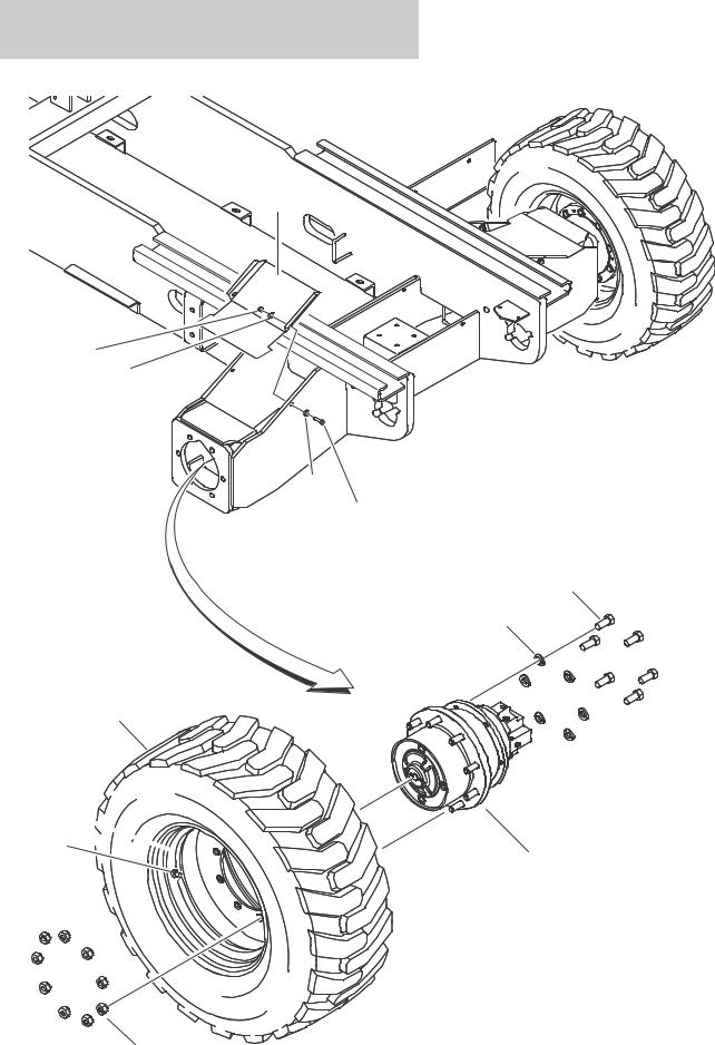
FIGURE 1-3.TIRE AND WHEEL DRIVE INSTALLATIONS
7
8
9
9
6
1
2
5
101
103
102 
3
4
1-10 |
3394RT & 4394RT |
3121836 |

SECTION 1 FRAME
FIGURE 1-3. TIRE AND WHEEL DRIVE INSTALLATIONS
ITEM # |
PART NUMBER |
QTY. |
DESCRIPTION |
REV. |
|
|
|
|
|
|
|
Ref |
WHEEL DRIVE INSTALLATIONS |
|
|
0271695 |
Ref |
2WD |
D |
|
0271508 |
Ref |
4WD |
E |
|
|
Ref |
Note: Quantities are per axle. |
|
1 |
0100019 |
AR |
Locking, Compound |
|
2 |
0682012 |
12 |
Bolt 5/8-11NC x 1-1/2 |
|
3 |
|
2 |
Drive Motor/Hub Assembly Options (See DRIVE MOTOR/HUB |
|
|
|
|
ASSEMBLY for Breakdown): |
|
|
2780263 |
|
2WD |
|
|
2780262 |
|
4WD |
|
4 |
3300106 |
18 |
Lugnut |
|
5 |
4892000 |
12 |
Washer, Hardened |
|
6 |
0641610 |
4 |
Bolt 3/8-16NC x 1-1/4 |
|
7 |
1671056 |
2 |
Cover, Rear Axle |
|
8 |
3311605 |
4 |
Locknut 3/8-16NC |
|
9 |
4711600 |
8 |
Flatwasher 3/8 Narrow |
|
|
|
Ref |
TIRE AND WHEEL INSTALLATIONS |
|
|
0270092 |
Ref |
12 x 16.5 Foam-Filled Lug Tire |
A |
|
0270653 |
Ref |
12 x 16.5 Foam-Filled Non-Marking Tires |
A |
|
0271719 |
Ref |
33/16LL x 16.5 Foam-Filled Lug Tire |
A |
|
0270076 |
2 |
12 x 16.5 Foam-Filled Right Side Lug Tire |
A |
|
0270077 |
2 |
12 x 16.5 Foam-Filled Left Side Lug Tire |
A |
|
0270654 |
2 |
12 x 16.5 Foam-Filled Right Side Non-Marking Tire |
A |
|
0270655 |
2 |
12 x 16.5 Foam-Filled Left Side Non-Marking Tire |
A |
|
0258011 |
2 |
33/16LL x 16.5 Foam-Filled Right Side Lug Tire |
D |
|
0258012 |
2 |
33/16LL x 16.5 Foam-Filled Left Side Lug Tire |
D |
|
|
Ref |
Note: Assemblies may require ballast/foam filling to |
|
|
|
|
manufacturer’s specifications prior to installing on a |
|
|
|
|
machine. Refer to Operation & Safety or Service & |
|
|
|
|
Maintenance Manuals. Purchase individual tire and/or rim |
|
|
|
|
only if able to foam fill tire & wheel assembly, |
|
|
|
|
otherwise, purchase complete assembly, |
|
102 |
|
1 |
Tire Options: |
|
|
4520216 |
|
12 x 16.5 NHS Lug Tire |
|
|
4520240 |
|
12 x 16.5 OTR NHS Non-Marking Tire |
|
|
4520217 |
|
33/16LL x 16.5 Lug Tire |
|
103 |
|
1 |
Valve, Air Options: |
|
|
8786514 |
|
With 0258011 & 0258012 Tire/Wheel Assemblies |
|
|
4640113 |
|
All Tire/Wheel Assemblies except 025811 & 0258012 |
|
104 |
|
1 |
Rim, Wheel |
|
|
4860213 |
|
16.5 x 9.75 (Use with 12 x 16.5 Lug Tires) |
|
|
4860179 |
|
16.5 x 12 (Use with 33/16LL x 16.5 Lug Tires) |
|
|
|
|
|
|
3121836 |
3394RT & 4394RT |
1-11 |

SECTION 1 FRAME
FIGURE 1-4. DRIVE MOTOR/HUB ASSEMBLY
10 |
14 |
5 |
56 |
53 |
51 |
54 52 |
43 |
49 |
16 8 |
21 |
22 |
34 |
|
|
|
|
|
|
|
|
|
|
33 |
2 |
|
|
|
|
|
|
|
|
|
|
|
17 |
|
|
|
|
|
|
|
|
|
|
7 |
15 |
|
|
|
|
|
|
|
|
|
|
3 |
1 11 |
|
|
|
|
|
|
|
|
|
|
30 |
224 |
|
|
|
|
|
|
|
|
|
|
29 |
|
|
|
|
|
|
|
|
|
|
|
4 |
|
|
|
|
|
|
|
|
|
|
|
6 |
88 |
|
|
|
|
|
|
|
|
|
|
19 |
44 |
|
|
|
|
|
|
|
|
|
|
23 |
55 |
|
|
|
|
|
|
|
|
|
|
12 |
|
|
|
|
|
|
|
|
|
|
|
20 |
60 |
|
|
|
|
|
|
|
|
|
|
|
|
|
|
|
|
|
|
|
|
|
301 302A 302B 303 304 305 |
|
|
|
|
|
|
|
|
|
|
28 |
|
|
|
|
|
|
|
|
|
|
|
27 |
|
|
120 |
|
|
|
|
|
|
|
|
|
|
|
1-12 |
3394RT & 4394RT |
3121836 |

SECTION 1 FRAME
FIGURE 1-4. DRIVE MOTOR/HUB ASSEMBLY
ITEM # |
PART NUMBER |
QTY. |
DESCRIPTION |
REV. |
|
|
|
|
|
|
|
Ref |
DRIVE MOTOR/HUB ASSEMBLY |
|
|
2780263 |
Ref |
2WD |
B |
|
2780262 |
Ref |
4WD |
B |
|
|
Ref |
Note: Unless there is capability to torque shaft (item 4) to 626 |
|
|
|
|
ft/lbs. (850Nm) Repair beyond this level is NOT advised. |
|
1 |
Use 7022544 |
4 |
Gear, Planet |
|
2 |
See Note |
3 |
Gear, Planet (Note: Use Item 302A or 302B) |
|
3 |
7021325 |
1 |
Gear, Sun |
|
4 |
Use 7024047 |
1 |
Nut, Shaft |
|
|
|
Ref |
Note: Unless there is capability to torque shaft nut (item 4) to |
|
|
|
|
626 ft/lbs. (850Nm) Repair beyond this level is NOT advised. |
|
5 |
7021326 |
3 |
Pin, Planet |
|
6 |
7021327 |
1 |
Ring, Support |
|
7 |
7021328 |
1 |
Carrier, Planet |
|
8 |
Use 7021329 |
1 |
Cover |
|
9 |
Not Used |
|
|
|
10 |
See Note |
3 |
Bearing, Roller (Note: Use Item 302A or 302B) |
|
11 |
Use 7022544 |
4 |
Bearing, Roller |
|
12 |
Use 7024047 |
2 |
Bearing, Tapered Roller |
|
13 |
Not Used |
|
|
|
14 |
See Note |
3 |
Ring, Retaining (Note: Use Item 302A or 302B) |
|
15 |
Use 7022544 |
4 |
Ring, Retaining |
|
16 |
7021341 |
1 |
Ring, Retaining |
|
17 |
See Note |
3 |
Disk, Support (Note: Use Item 302A or 302B) |
|
18 |
Not Used |
|
|
|
19 |
Use 7024047 |
1 |
O-Ring |
|
20 |
Use 7024047 |
1 |
Seal, Shaft |
|
21 |
Use 7021329 |
3 |
Plug, screw |
|
22 |
7024048 |
3 |
Ring, Seal |
|
23 |
Use 7024047 |
3 |
Bolt |
|
24 to 26 |
Not Used |
|
|
|
27 |
70002303 |
1 |
O-Ring |
|
28 |
70002304 |
1 |
Seal |
|
29 |
7024049 |
1 |
Washer, Thrust |
|
30 |
|
1 |
Gear, Ring Options: |
|
|
7021335 |
|
2WD |
|
|
7021346 |
|
4WD |
|
31 to 32 |
Not Used |
|
|
|
33 |
See Note |
1 |
O-Ring (Note: Use Item 303 or 304) |
|
34 |
Use 7021329 |
1 |
Ring, Retaining |
|
35 to 42 |
Not Used |
|
|
|
43 |
|
1 |
Shaft, Sun Gear Options: |
|
|
7021336 |
|
2WD |
|
|
7021347 |
|
4WD |
|
44 |
7024050 |
1 |
Shaft, Input |
|
45 to 48 |
Not Used |
|
|
|
49 |
7024051 |
1 |
Washer, Thrust |
|
50 |
Not Used |
|
|
|
|
|
|
|
|
3121836 |
3394RT & 4394RT |
1-13 |

SECTION 1 FRAME
FIGURE 1-4. DRIVE MOTOR/HUB ASSEMBLY (CONTINUED)
ITEM # |
PART NUMBER |
QTY. |
DESCRIPTION |
REV. |
|
|
|
|
|
51 |
See Note |
1 |
Cover (Note: Use Item 304 or 305) |
|
52 |
Use 7021329 |
1 |
Sleeve |
|
53 |
See Note |
2 |
Bolt (Note: Use Item 304 or 305) |
|
54 |
See Note |
1 |
O-Ring (Note: Use Item 304 or 305) |
|
55 |
7024053 |
1 |
Spring |
|
56 |
Use 7024054 |
1 |
Rod, Shift |
|
57 to 59 |
Not Used |
|
|
|
60 |
Not Available |
1 |
Housing, Brake |
|
61 to 87 |
Not Used |
|
|
|
88 |
7021344 |
9 |
Stud, Wheel |
|
89 to 99 |
Not Used |
|
|
|
100 |
7022552 |
9 |
Cap, Seal |
|
101 to 119 |
Not Used |
|
|
|
120 |
7024055 |
1 |
Motor, Hydraulic |
|
121 to 223 |
Not Used |
|
|
|
224 |
Use 7024047 |
2 |
Dowel, Spring Sleeve |
|
|
|
Ref |
REPAIR KIT OPTIONS |
|
301 |
7022544 |
1 |
Planet Gear Kit (Includes Items 1,11,15) |
|
302 |
|
1 |
Planet Gear Kit Options: (Includes Items 2,10, 14,17) |
|
302A |
7024027 |
|
2WD |
|
302B |
7022545 |
|
4WD |
|
303 |
7024047 |
1 |
Bearing Kit (Includes Items 4,12,19,20,23,33, 224) |
|
|
|
Ref |
Note: Unless there is capability to torque shaft nut (item 4) to |
|
|
|
|
626 ft/lbs. (850Nm) Repair beyond this level is NOT advised. |
|
304 |
7021329 |
1 |
Cover Kit (Includes Items 8,21,22,33,34,51,52,53,54) |
|
305 |
7024054 |
1 |
Mechanical Disconnect Kit (Includes 51,53,54, 56) |
|
|
|
|
|
|
1-14 |
3394RT & 4394RT |
3121836 |
SECTION 1 FRAME
FIGURE 1-4. DRIVE MOTOR/HUB ASSEMBLY (CONTINUED)
ITEM # |
PART NUMBER |
QTY. |
DESCRIPTION |
REV. |
|
|
|
|
|
|
|
|
|
|
3121836 |
3394RT & 4394RT |
1-15 |
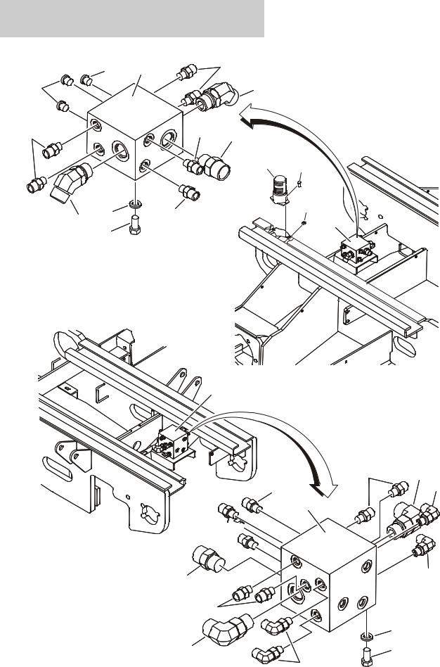
SECTION 1 FRAME
FIGURE 1-5. BEACON LIGHT AND 4WD VALVE INSTALLATIONS (FRAME MOUNTED)
105 |
101 |
102 |
|
||
105 |
|
104 |
102 |
102 |
103 |
REAR
|
|
|
303 |
301 |
|
|
|
|
|
|
6 |
102 |
|
304 |
104 |
|
4 |
||
1 |
|
|
||
|
|
|
|
7
FRONT
202 205
202 |
202 |
|
201
202 


203 |
202 |
|
202
6
205 |
1 |
|
204
1-16 |
3394RT & 4394RT |
3121836 |

SECTION 1 FRAME
FIGURE 1-5. BEACON LIGHT AND 4WD VALVE INSTALLATIONS (FRAME MOUNTED)
ITEM # |
PART NUMBER |
QTY. |
DESCRIPTION |
REV. |
|
|
|
|
|
|
0271779 |
Ref |
4WD VALVE INSTALLATIONS (FRAME MOUNTED) |
C |
1 |
0641606 |
8 |
Bolt 3/8-16NC x 3/4 |
|
2 to 3 |
Not Used |
|
|
|
4 |
4641225 |
1 |
Valve Assembly - 4WD Rear Axle (See Items 101 to 105 for |
|
|
|
|
Breakdown) |
|
5 |
Not Used |
|
|
|
6 |
4761600 |
2 |
Lockwasher 3/8 |
|
7 |
4641220 |
1 |
Valve Assembly - 4WD Front Axle (See Items 201 to 205 for |
|
|
|
|
Breakdown) |
|
|
4641225 |
Ref |
VALVE ASSEMBLY - REAR AXLE (4WD) |
C |
101 |
Not Available |
1 |
Block, Manifold |
|
102 |
2110404 |
6 |
Fitting, Straight |
|
103 |
2111010 |
1 |
Fitting, Straight |
|
104 |
2151010 |
2 |
Fitting, 45 |
|
105 |
Not Available |
3 |
Orifice |
|
|
4641220 |
Ref |
VALVE ASSEMBLY - FRONT AXLE (4WD) |
C |
201 |
Not Available |
1 |
Block, Manifold |
|
202 |
2110404 |
8 |
Fitting, Straight |
|
203 |
2111010 |
1 |
Fitting, Straight |
|
204 |
2130404 |
4 |
Fitting, 90 |
|
205 |
2131010 |
2 |
Fitting, 90 |
|
|
0271746 |
Ref |
BEACON LIGHT INSTALLATION |
A |
301 |
0721004 |
2 |
Screw #10-24NC x 1/2 |
|
302 |
2820018 |
2in/8cm |
Heat-Shrink (Not Shown) |
|
303 |
2920146 |
1 |
Beacon Light Assembly |
|
|
7016319 |
1 |
Bulb, Replacement |
|
|
7016372 |
1 |
Lens, Replacement |
|
304 |
3311005 |
2 |
Locknut #10-24NC |
|
305 |
4922739 |
1 |
Harness, Beacon Light (Not Shown - See ELECTRICAL |
|
|
|
|
SECTION for Breakdown) |
|
|
|
|
|
|
3121836 |
3394RT & 4394RT |
1-17 |

SECTION 1 FRAME
FIGURE 1-6. LEVELING JACKS INSTALLATION
2
|
8 |
PRIOR TO |
|
|
|
8 |
|
|
|
|
|
|
|
||
|
102 |
|
|
|
|
|
|
|
SN 0200139319 |
|
|
|
|
|
|
|
20 |
23 11 |
SN 0200139319 |
|
|
|
|
|
4 |
16 |
TO PRESENT |
|
|
|
|
|
|
|
|
|
|
|
|
|
110 104 |
15 |
|
|
|
|
|
105 |
103 |
19 |
|
|
|
|
|
109 |
|
|
|
|
|
||
106 |
7 |
|
|
|
20 |
1 |
|
|
|
|
|
||||
|
112 |
12 |
26 |
|
|
4 |
|
|
|
|
|
|
|||
|
|
6 |
14 |
1 |
20 |
28 |
|
|
|
|
|||||
101 |
|
22 |
26 |
4 |
|
||
|
10 |
|
113 |
|
|||
|
|
|
|
|
|||
|
|
|
|
|
|
|
|
|
108 |
|
|
|
|
|
|
|
107 |
|
|
|
|
|
|
|
|
|
|
|
|
252 |
|
|
|
24 |
|
|
|
220 |
|
|
|
|
|
|
|
|
|
|
|
22 |
|
|
|
|
|
|
|
111 |
|
|
|
|
|
|
|
13 |
|
|
|
|
|
|
|
25 |
|
|
|
18 |
|
|
|
|
|
|
|
|
|
1-18 |
3394RT & 4394RT |
3121836 |

SECTION 1 FRAME
FIGURE 1-6. LEVELING JACKS INSTALLATION
ITEM # |
PART NUMBER |
QTY. |
DESCRIPTION |
REV. |
|
|
|
|
|
|
|
Ref |
LEVELING JACKS INSTALLATIONS: |
|
|
0271776 |
Ref |
Prior to SN 0200139319 |
F |
|
0274623 |
Ref |
SN 0200139319 to SN 0200191606 |
B |
1 |
0100011 |
AR |
Locking, Compound (Not Shown) |
|
2 |
|
2 |
Leveling Jack Assembly Options (See Items 101-113 for |
|
|
|
|
Breakdown): |
|
|
0272261 |
|
Prior to SN 0200139319 |
|
|
0274622 |
|
SN 0200139319 to SN 0200191606 |
|
3 |
0272278 |
1 |
Directional Valve Assembly (Not Shown - See GROUND |
|
|
|
|
CONTROLS SECTION for Breakdown) |
|
4 |
|
AR |
Bolt Options: |
|
|
0641406 |
8 |
Bolt 1/4-20NC x 3/4 (Prior to SN 0200139319) |
|
|
0641407 |
16 |
Bolt 1/4-20NC x 7/8 (SN 0200139319 to SN 0200191606) |
|
5 |
Not Used |
|
|
|
6 |
0641811 |
8 |
Bolt 1/2-13NC x 1-3/8 |
|
7 |
0682226 |
16 |
Bolt 3/4-10NC x 3-1/4 |
|
8 |
|
4 |
Cover Options: |
|
|
1671071 |
4 |
Prior to SN 0200139319 |
|
|
1671165 |
4 |
SN 0200139319 to SN 0200191606 |
|
9 |
Not Used |
|
|
|
10 |
3272205 |
16 |
Locknut 3/4-10NC |
|
11 |
3310805 |
8 |
Locknut #8-32NC |
|
12 |
3311405 |
8 |
Locknut 1/4-20NC (Prior to SN 0200139319) |
|
13 |
3311805 |
8 |
Locknut 1/2-13NC |
|
14 |
3573658 |
4 |
Plate |
|
15 |
3930820 |
8 |
Capscrew #8-32NC |
|
16 |
|
4 |
Switch, Limit Options: |
|
|
4360548 |
|
Prior to SN 0200115380 |
|
|
See Note |
|
SN 0200115380 to SN 0200191606 (Note: See |
|
|
|
|
ELECTRICAL SECTION) |
|
17 |
Not Used |
|
|
|
18 |
|
AR |
Tape, Safety Options: |
|
|
4420052 |
3ft/1m |
Prior to SN 0200139319 |
|
|
4420052 |
8ft/2.4m |
SN 0200139319 to SN 0200149813 |
|
|
4420051 |
8ft/2.4m |
SN 0200149813 to SN 0200191606 |
|
19 |
4460968 |
4 |
Connector, Strain Relief (Prior to SN 0200115380) |
|
20 |
4711400 |
AR |
Flatwasher 1/4 Narrow |
|
21 |
Not Used |
|
|
|
22 |
4711800 |
16 |
Flatwasher 1/2 Narrow |
|
23 |
4750800 |
8 |
Flatwasher #8 Thick |
|
24 |
4846620 |
2 |
Support (Front Right/Rear Left) |
|
25 |
4846621 |
2 |
Support (Front Left/Rear Right) |
|
26 |
4892200 |
32 |
Washer, Hardened 3/4 |
|
27 |
4922748 |
1 |
Harness, Leveling Jack (See ELECTRICAL SECTION for |
|
|
|
|
Breakdown) |
|
28 |
3300353 |
16 |
Nut, Tinnerman (SN 0200139319 to SN 0200191606) |
|
|
|
|
|
|
3121836 |
3394RT & 4394RT |
1-19 |

SECTION 1 FRAME
FIGURE 1-6. LEVELING JACKS INSTALLATION (CONTINUED)
ITEM # |
PART NUMBER |
QTY. |
DESCRIPTION |
REV. |
|
|
|
|
|
|
|
Ref |
LEVELING JACK ASSEMBLIES: |
|
|
0272261 |
Ref |
Prior to SN 0200139319 |
C |
|
0274622 |
Ref |
SN 0200139319 to SN 0200191606 |
A |
|
|
Ref |
Note: Qty shown is for one Level Jack Assembly. Two |
|
|
|
|
assemblies required per machine. |
|
101 |
0641824 |
8 |
Bolt 1/2-13NC x 3 |
|
102 |
|
2 |
Jack Cylinder Assembly Options (See CYLINDER SECTION for |
|
|
|
|
Breakdown): |
|
|
1684220 |
|
Prior to SN 0200139319 |
|
|
1684406 |
|
SN 0200139319 to SN 0200191606 |
|
103 |
2110606 |
2 |
Fitting, Straight |
|
104 |
2220883 |
2 |
Plug |
|
105 |
3311805 |
8 |
Locknut 1/2-13NC |
|
106 |
3760348 |
2 |
Ring, Retaining |
|
107 |
3841564 |
2 |
Rod |
|
108 |
4160116 |
2 |
Spring |
|
109 |
4360518 |
2 |
Transducer, Pressure |
|
110 |
4641238 |
2 |
Cartridge, Solenoid Valve |
|
|
7024502 |
2 |
Seal Kit - 4641238 Valve (1 Per Cartridge) |
|
|
7024501 |
2 |
Coil (1 Per Cartridge) |
|
|
7024506 |
2 |
Coil Nut Kit (1 Per Cartridge) |
|
111 |
|
1 |
Mount, Leveling Jack Options: |
|
|
4846619 |
|
Prior to SN 0200139319 |
|
|
4210028 |
|
SN 0200139319 to SN 0200191606 |
|
112 |
2110808 |
2 |
Fitting, Straight |
|
113 |
0903054 |
2 |
Bracket, Jack Cover (SN 0200139319 to SN 0200191606) |
|
|
0010583 |
Ref |
DECALS INSTALLATION |
|
201 to 219 |
Not Used |
|
|
|
220 |
|
4 |
Decal - Outrigger Warning Options: |
|
|
1701214 |
|
ANSI Spec (English) |
|
|
1704690 |
|
CSA Spec (English/French) |
|
|
1704698 |
|
Brazilian Spec (Spanish/Portuguese) |
|
|
1704697 |
|
Latin American Spec (English/Spanish) |
|
221 to 251 |
Not Used |
|
|
|
252 |
1705042 |
4 |
Decal - Maximum Load |
|
|
|
|
|
|
1-20 |
3394RT & 4394RT |
3121836 |
SECTION 2
GROUND CONTROLS
3121836 |
3394RT & 4394RT |
2-1 |
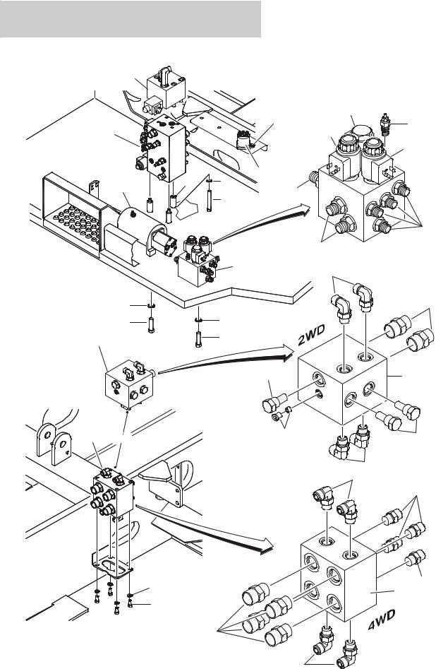
SECTION 2 GROUND CONTROLS
FIGURE 2-1. CONTROL VALVES INSTALLATION
602 |
|
|
|
|
|
|
|
|
503 |
404B |
|
|
|
|
530 |
|
|
|
|
|
516 |
|
404C |
3 |
|
|
|
404A |
|
|
|
|
|
||
|
|
|
|
|
404D |
|
8 |
5 |
519 |
|
|
518 |
402 |
|
|
||
|
|
|
|
||
|
|
2 |
|
|
|
|
|
|
|
|
|
|
|
|
|
|
401 |
|
|
|
|
402 |
|
|
|
303 |
|
|
|
TANK SIDE |
|
404 |
|
104 |
|
531 |
|
|
|
|
102 |
502 |
|
321 |
|
|
|
504 |
|
301 |
|
|
|
|
|
|
|
|
|
4A |
|
305 |
|
|
|
|
|
|
105 |
|
101 |
4B OR |
106 |
107 |
|
104
204
202
5 |
202 |
|
201 |
||
|
||
1 |
|
|
|
203 |
|
ENGINE SIDE |
|
|
|
204 |
2-2 |
3394RT & 4394RT |
3121836 |

SECTION 2 GROUND CONTROLS
FIGURE 2-1. CONTROL VALVES INSTALLATION
ITEM # |
PART NUMBER |
QTY. |
DESCRIPTION |
REV. |
|
|
|
|
|
|
|
Ref |
CONTROL VALVE INSTALLATION |
|
|
0271778 |
Ref |
2WD |
B |
|
0271779 |
Ref |
4WD |
C |
1 |
0641606 |
4 |
Bolt 3/8-16NC x 3/4 |
|
2 |
0641624 |
3 |
Bolt 3/8-16NC x 3 |
|
3 |
4641211 |
1 |
Valve Assembly - Main (See MAIN CONTROL VALVE |
|
|
|
|
ASSEMBLY for Breakdown) |
|
4 |
|
1 |
Valve Assembly - Drive Header Options: |
|
4A |
4641228 |
|
2WD (See Items 101-106 for Breakdown) |
|
4B |
4641227 |
|
4WD (See Items 201-204 for Breakdown) |
|
5 |
4761600 |
7 |
Lockwasher 3/8 |
|
6 to 7 |
Not Used |
|
|
|
8 |
4568114 |
3 |
Spacer, Tube |
|
|
4641228 |
Ref |
VALVE ASSEMBLY - DRIVE HEADER (2WD) |
C |
101 |
Not Available |
1 |
Block, Manifold |
|
102 |
2111212 |
2 |
Fitting, Straight |
|
103 |
Not Used |
|
|
|
104 |
2130808 |
4 |
Fitting, 90 |
|
105 |
7026010 |
1 |
Cartridge |
|
|
70002519 |
1 |
Seal Kit - 7026010 Cartridge |
|
106 |
7018905 |
1 |
Plug, O-Ring |
|
|
7022523 |
1 |
Orifice |
|
107 |
7026012 |
2 |
Cartridge |
|
|
7011346 |
2 |
Seal Kit - 7026012 Cartridge |
|
|
4641227 |
Ref |
VALVE ASSEMBLY - DRIVE HEADER (4WD) |
C |
201 |
Not Available |
1 |
Block, Manifold |
|
202 |
2110808 |
4 |
Fitting, Straight |
|
203 |
2111212 |
4 |
Fitting, Straight |
|
204 |
2130808 |
4 |
Fitting, 90 |
|
|
|
Ref |
LEVELING JACK VALVE INSTALLATION |
B |
|
0271776 |
Ref |
Prior to SN 0200139319 |
|
|
0274623 |
Ref |
SN 0200139319 to SN 0200191606 |
|
301 |
0100011 |
AR |
Locking, Compound |
|
302 |
Not Used |
|
|
|
303 |
0272278 |
1 |
Leveling Jack Valve Assembly (See Items 401-403 for |
|
|
|
|
Breakdown) |
|
304 |
Not Used |
|
|
|
305 |
0641508 |
3 |
Bolt 5/16-18NC x 1 |
|
306 to 320 |
Not Used |
|
|
|
321 |
4711500 |
3 |
Flatwasher 5/16 Narrow |
|
|
|
|
|
|
3121836 |
3394RT & 4394RT |
2-3 |

SECTION 2 GROUND CONTROLS
FIGURE 2-1. CONTROL VALVES INSTALLATION (CONTINUED)
ITEM # |
PART NUMBER |
QTY. |
DESCRIPTION |
REV. |
|
|
|
|
|
|
0272278 |
Ref |
LEVELING JACK VALVE SUB-ASSEMBLY |
C |
401 |
2110606 |
4 |
Fitting, Straight |
|
402 |
2110808 |
6 |
Fitting, Straight |
|
403 |
Not Used |
|
|
|
404 |
4641240 |
1 |
Valve Assembly |
|
404A |
7024497 |
1 |
Cartridge without Coil (Retract) |
|
|
7024502 |
1 |
Seal Kit - 7024497 Cartridge |
|
|
7024501 |
1 |
Coil |
|
|
7024506 |
1 |
Coil Nut Kit |
|
404B |
7024498 |
1 |
Cartridge without Coil (Extend) |
|
|
7024503 |
1 |
Seal Kit - 7024498 Cartridge |
|
|
7024501 |
1 |
Coil |
|
|
7024507 |
1 |
Coil Nut Kit |
|
404C |
7024499 |
1 |
Cartridge |
|
|
7024504 |
1 |
Seal Kit - 7024499 Cartridge |
|
404D |
7024500 |
1 |
Cartridge without Coil |
|
|
7024505 |
1 |
Seal Kit - 7024500 Cartridge |
|
|
7024501 |
1 |
Coil |
|
|
7024506 |
1 |
Coil Nut Kit |
|
|
|
Ref |
POWER DECK EXTENSION AUXILIARY PUMP INSTALLATION |
|
|
0271701 |
Ref |
3394RT with Single Deck Extension |
E |
|
0271705 |
Ref |
3394RT with Dual Deck Extension |
E |
|
0271702 |
Ref |
4394RT with Single Deck Extension |
E |
|
0271706 |
Ref |
4394RT with Dual Deck Extension |
E |
501 |
Not Used |
|
|
|
502 |
0100011 |
AR |
Locking, Compound |
|
503 |
0641405 |
2 |
Bolt 1/4-20NC x 5/8 |
|
504 |
0641608 |
2 |
Bolt 3/8-16NC x 1 |
|
505 to 515 |
Not Used |
|
|
|
516 |
3311405 |
2 |
Locknut 1/4-20NC |
|
517 |
Not Used |
|
|
|
518 |
|
1 |
Auxiliary Power Pump Assembly Options (see AUXILIARY |
|
|
|
|
PUMP ASSEMBLY for Breakdown): |
|
|
Use 3600468 |
1 |
Prior to SN 0200164133 (was p/n 3600208) |
|
|
3600468 |
1 |
SN 0200164133 to SN 0200191606 |
|
519 |
3740067 |
1 |
Relay |
|
520 to 529 |
Not Used |
|
|
|
530 |
4751400 |
4 |
Flatwasher 1/4 Wide |
|
531 |
4751600 |
2 |
Flatwasher 3/8 Wide |
|
|
|
|
|
|
2-4 |
3394RT & 4394RT |
3121836 |
Loading...