


JLG 40RTS Service Manual
SERVICE & MAINTENANCE
Model
25RTS
33RTS
40RTS
AUSTRALIAN OFFICE
JLG INDUSTRIES, INC.
P.O. Box 5119
11 Bolwarra Road
Port Macquarie, Australia
Telephone: 065 811111
Fax: 065 810122
3120826
March 12, 2004
EUROPEAN OFFICE
JLG INDUSTRIES (EUROPE)
Kilmartin Place,
Tannochs i d e Park
Uddingston, Scotland, G71 5PH
Telephone: 01698 811005
Main Fax: 01698 811055
Parts Fax: 01698 811455
CORPORATE OFFICE
JLG INDUSTRIES, INC.
1 JLG Drive
McConnellsburg, PA.
17233-9533
USA
Telephone: (717) 485-5161
Fax: (717) 485-6417

INTRODUCTION - MAINTENANCE SAFETY PRECAUTIONS
SECTION A. INTRODUCTION - MAINTENANCE SAFETY
PRECAUTIONS
A.A GENERAL
This section contains the general safety precautions
which must be observed during maintenance of the
aerial platform. It is of utmost importance that maintenance personnel pay strict attention to these warnings and precautions to avoid possible injury to
themselves or others, or damage to the equipment.
A maintenance program must be followed to ensure
that the machine is safe to operate.
MODIFICATION OF THE MACHINE WITHOUT CERTIFICATION BY A RESPONSIBLE AUTHORITY THAT THE
MACHINE IS AT LEAST AS SAFE AS ORIGINALLY
MANUFACTURED, IS A SAFETY VIOLATION.
The specific precautions to be observed during
maintenance are inserted at the appropriate point in
the manual. These precautions are, for the most
part, those that apply when servicing hydraulic and
larger machine component parts.
Your safety, and that of others, is the first consideration when engaging in the maintenance of equipment. Always be conscious of weight. Never attempt
to move heavy parts without the aid of a mechanical
device. Do not allow heavy objects to rest in an
unstable position. When raising a portion of the
equipment, ensure that adequate support is provided.
SINCE THE MACHINE MANUFACTURER HAS NO
DIRECT CONTROL OVER THE FIELD INSPECTION
AND MAINTENANCE, SAFETY IN THIS AREA RESPONSIBILITY OF THE OWNER/OPERATOR.
A.B HYDRAULIC SYSTEM SAFETY
It should be noted that the machines hydraulic systems operate at extremely high potentially dangerous pressures. Every effort should be made to
relieve any system pressure prior to disconnecting
or removing any portion of the system.
Relieve system pressure by cycling the applicable
control several times with the engine stopped and
ignition on, to direct any line pressure back into the
reservoir. Pressure feed lines to system components
can then be disconnected with minimal fluid loss.
A.C MAINTENANCE
FAILURE TO COMPLY WITH SAFETY PRECAUTIONS
LISTED IN THIS SECTION MAY RESULT IN MACHINE
DAMAGE, PERSONNEL INJURY OR DEATH AND IS A
SAFETY VIOLATION.
• NO SMOKING IS MANDATORY. NEVER REFUEL DURING ELECTRICAL STORMS. ENSURE THAT FUEL CAP
IS CLOSED AND SECURE AT ALL OTHER TIMES.
• REMOVE ALL RINGS, WATCHES AND JEWELRY WHEN
PERFORMING ANY MAINTENANCE.
• DO NOT WEAR LONG HAIR UNRESTRAINED, OR
LOOSE-FITTING CLOTHING AND NECKTIES WHICH
ARE APT TO BECOME CAUGHT ON OR ENTANGLED
IN EQUIPMENT.
• OBSERVE AND OBEY ALL WARNINGS AND CAUTIONS ON MACHINE AND IN SERVICE MANUAL.
• KEEP OIL, GREASE, WATER, ETC. WIPED FROM
STANDING SURFACES AND HAND HOLDS.
• USE CAUTION WHEN CHECKING A HOT, PRESSURIZED COOLANT SYSTEM.
• NEVER WORK UNDER AN ELEVATED BOOM UNTIL
BOOM HAS BEEN SAFELY RESTRAINED FROM ANY
MOVEMENT BY BL OCKING OR OV ERHEAD SL ING,
OR BOOM SAFETY PROP HAS BEEN ENGAGED.
• BEFORE MAKING ADJUSTMENTS, LUBRICATING OR
PERFORMING ANY OTHER MAINTENANCE, SHUT OFF
ALL POWER CONTROLS.
• BATTER Y SHOULD ALWAYS BE DISCONNECTED DURING REPLACEMENT OF ELECTRICAL COMPONENTS.
• KEEP ALL SUPPOR T EQUIPMENT AND ATTACHMENTS
STOWED IN THEIR PROPER PLACE.
• USE ONLY APPROVED, NONFLAMMABLE CLEANING
SOLVENTS.
3120826 – JLG Sizzor – a

INTRODUCTION - MAINTENANCE SAFETY PRECAUTIONS
REVISON LOG
Original Issue - June 1993
Revised - August 24, 1999
Revised - September 30, 1999
Revised - February 29, 2000
Revised - March 14, 2001
Revised - September 18, 2001
Revised - April 15, 2002
Revised - September 25, 2002
Revised - March 12, 2004
b – JLG Sizzor – 3120826

TABLE OF CONTENTS
TABLE OF CONTENTS
SUBJECT - SECTION, PARAGRAPH PAGE NO.
SECTION A - INTRODUCTION - MAINTENANCE SAFETY PRECAUTIONS
A.A General . . . . . . . . . . . . . . . . . . . . . . . . . . . . . . . . . . . . . . . . . . . . . . . . . . . . . . . . . . . . . . . . . . . . . . a
A.B Hydraulic System Safety . . . . . . . . . . . . . . . . . . . . . . . . . . . . . . . . . . . . . . . . . . . . . . . . . . . . . . . . a
A.C Maintenance . . . . . . . . . . . . . . . . . . . . . . . . . . . . . . . . . . . . . . . . . . . . . . . . . . . . . . . . . . . . . . . . . . a
SECTION 1 - SPECIFICATIONS
1.1 Capacities . . . . . . . . . . . . . . . . . . . . . . . . . . . . . . . . . . . . . . . . . . . . . . . . . . . . . . . . . . . . . . . . . . . . 1-1
1.2 Component Data . . . . . . . . . . . . . . . . . . . . . . . . . . . . . . . . . . . . . . . . . . . . . . . . . . . . . . . . . . . . . . 1-1
1.3 Performance Data. . . . . . . . . . . . . . . . . . . . . . . . . . . . . . . . . . . . . . . . . . . . . . . . . . . . . . . . . . . . . . 1-2
1.4 Lubrication . . . . . . . . . . . . . . . . . . . . . . . . . . . . . . . . . . . . . . . . . . . . . . . . . . . . . . . . . . . . . . . . . . . 1-2
1.5 Pressure Settings . . . . . . . . . . . . . . . . . . . . . . . . . . . . . . . . . . . . . . . . . . . . . . . . . . . . . . . . . . . . . . 1-6
1.6 Serial Number Locations . . . . . . . . . . . . . . . . . . . . . . . . . . . . . . . . . . . . . . . . . . . . . . . . . . . . . . . . 1-7
1.7 Limit Switches. . . . . . . . . . . . . . . . . . . . . . . . . . . . . . . . . . . . . . . . . . . . . . . . . . . . . . . . . . . . . . . . . 1-7
1.8 Cylinder Specifications. . . . . . . . . . . . . . . . . . . . . . . . . . . . . . . . . . . . . . . . . . . . . . . . . . . . . . . . . . 1-7
1.9 Major Component Weights. . . . . . . . . . . . . . . . . . . . . . . . . . . . . . . . . . . . . . . . . . . . . . . . . . . . . . . 1-8
1.10 Critical Stability Weights. . . . . . . . . . . . . . . . . . . . . . . . . . . . . . . . . . . . . . . . . . . . . . . . . . . . . . . . . 1-8
SECTION 2 - PROCEDURES
2.1 General . . . . . . . . . . . . . . . . . . . . . . . . . . . . . . . . . . . . . . . . . . . . . . . . . . . . . . . . . . . . . . . . . . . . . . 2-1
2.2 Servicing and Maintenance Guidelines . . . . . . . . . . . . . . . . . . . . . . . . . . . . . . . . . . . . . . . . . . . . .2-1
2.3 Lubrication Information. . . . . . . . . . . . . . . . . . . . . . . . . . . . . . . . . . . . . . . . . . . . . . . . . . . . . . . . . . 2-2
2.4 Cylinders - Theory of Operation . . . . . . . . . . . . . . . . . . . . . . . . . . . . . . . . . . . . . . . . . . . . . . . . . . . 2-3
2.5 Valves - Theory of Operation . . . . . . . . . . . . . . . . . . . . . . . . . . . . . . . . . . . . . . . . . . . . . . . . . . . . . 2-3
2.6 Component Functional Description . . . . . . . . . . . . . . . . . . . . . . . . . . . . . . . . . . . . . . . . . . . . . . . . 2-4
2.7 Sliding Wear Pads . . . . . . . . . . . . . . . . . . . . . . . . . . . . . . . . . . . . . . . . . . . . . . . . . . . . . . . . . . . . . 2-4
2.8 Pump and Coupling Lubrication . . . . . . . . . . . . . . . . . . . . . . . . . . . . . . . . . . . . . . . . . . . . . . . . . . 2-4
2.9 Cylinder Checking Procedures . . . . . . . . . . . . . . . . . . . . . . . . . . . . . . . . . . . . . . . . . . . . . . . . . . . 2-4
2.10 Cylinder Removal and Installation . . . . . . . . . . . . . . . . . . . . . . . . . . . . . . . . . . . . . . . . . . . . . . . . . 2-5
2.11 Cylinder Repair . . . . . . . . . . . . . . . . . . . . . . . . . . . . . . . . . . . . . . . . . . . . . . . . . . . . . . . . . . . . . . . . 2-6
2.12 Tilt Alarm Switch . . . . . . . . . . . . . . . . . . . . . . . . . . . . . . . . . . . . . . . . . . . . . . . . . . . . . . . . . . . . . . . 2-12
2.13 Limit Switch Adjustment Procedure . . . . . . . . . . . . . . . . . . . . . . . . . . . . . . . . . . . . . . . . . . . . . . . . 2-13
2.14 Drive Pump Start-up Procedure . . . . . . . . . . . . . . . . . . . . . . . . . . . . . . . . . . . . . . . . . . . . . . . . . . . 2-13
2.15 Throttle Checks and Adjustments - Ford . . . . . . . . . . . . . . . . . . . . . . . . . . . . . . . . . . . . . . . . . . . .2-14
2.16 Throttle Checks and Adjustments - Deutz . . . . . . . . . . . . . . . . . . . . . . . . . . . . . . . . . . . . . . . . . . .2-17
2.17 Automatic Choke Adjustment - Ford Engine . . . . . . . . . . . . . . . . . . . . . . . . . . . . . . . . . . . . . . . . . 2-17
2.18 Hydraulic Component Start-Up Procedures and Recommendations . . . . . . . . . . . . . . . . . . . . . . 2-18
2.19 Pressure Setting Procedures - (2 W/S) . . . . . . . . . . . . . . . . . . . . . . . . . . . . . . . . . . . . . . . . . . . . 2-19
2.20 Pressure Setting Procedures - (4 W/S) . . . . . . . . . . . . . . . . . . . . . . . . . . . . . . . . . . . . . . . . . . . . 2-21
2.21 Oscillating Axle Lockout Cylinder Bleeding Procedure . . . . . . . . . . . . . . . . . . . . . . . . . . . . . . . . . 2-21
2.22 Lockout Cylinder Check . . . . . . . . . . . . . . . . . . . . . . . . . . . . . . . . . . . . . . . . . . . . . . . . . . . . . . . . . 2-23
2.23 Piston Drive Motor . . . . . . . . . . . . . . . . . . . . . . . . . . . . . . . . . . . . . . . . . . . . . . . . . . . . . . . . . . . . . 2-23
2.24 Drive Torque Hub - 2WD/4WD Rear. . . . . . . . . . . . . . . . . . . . . . . . . . . . . . . . . . . . . . . . . . . . . . . . 2-27
2.25 Drive Torque Hub/Brake - 4WD Front . . . . . . . . . . . . . . . . . . . . . . . . . . . . . . . . . . . . . . . . . . . . . . 2-35
2.26 Drive Brake - 2WD/2WS Rear . . . . . . . . . . . . . . . . . . . . . . . . . . . . . . . . . . . . . . . . . . . . . . . . . . . . . 2-41
2.27 Spark Arrestor Muffler . . . . . . . . . . . . . . . . . . . . . . . . . . . . . . . . . . . . . . . . . . . . . . . . . . . . . . . . . . . 2-44
2.28 Dual Fuel/LPG System . . . . . . . . . . . . . . . . . . . . . . . . . . . . . . . . . . . . . . . . . . . . . . . . . . . . . . . . . . 2-44
2.29 Freewheeling Feature. . . . . . . . . . . . . . . . . . . . . . . . . . . . . . . . . . . . . . . . . . . . . . . . . . . . . . . . . . . 2-45
2.30 Preventive Maintenance and Inspection Schedule . . . . . . . . . . . . . . . . . . . . . . . . . . . . . . . . . . . . 2-46
SECTION 3 - TROUBLESHOOTING
3.1 General . . . . . . . . . . . . . . . . . . . . . . . . . . . . . . . . . . . . . . . . . . . . . . . . . . . . . . . . . . . . . . . . . . . . . . 3-1
3.2 Troubleshooting Information . . . . . . . . . . . . . . . . . . . . . . . . . . . . . . . . . . . . . . . . . . . . . . . . . . . . . 3-1
3.3 Hydraulic Circuit Checks . . . . . . . . . . . . . . . . . . . . . . . . . . . . . . . . . . . . . . . . . . . . . . . . . . . . . . . . 3-1
3120826 – JLG Sizzor – i

TABLE OF CONTENTS
LIST OF FIGURES
FIGURE NO. TITLE PAGE NO.
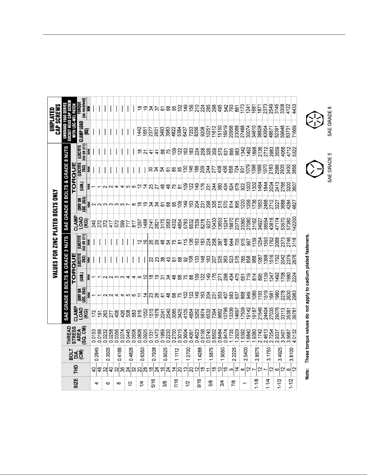
1-1. Torque Chart . . . . . . . . . . . . . . . . . . . . . . . . . . . . . . . . . . . . . . . . . . . . . . . . . . . . . . . . . . . . . . . . . .1-3
1-2. Lubrication Diagram . . . . . . . . . . . . . . . . . . . . . . . . . . . . . . . . . . . . . . . . . . . . . . . . . . . . . . . . . . . .1-4
1-3. Serial Number Location. . . . . . . . . . . . . . . . . . . . . . . . . . . . . . . . . . . . . . . . . . . . . . . . . . . . . . . . . .1-7
2-1. Pump and Coupling Lubrication . . . . . . . . . . . . . . . . . . . . . . . . . . . . . . . . . . . . . . . . . . . . . . . . . . .2-4
2-2. Top Lift Cylinder Pin Location . . . . . . . . . . . . . . . . . . . . . . . . . . . . . . . . . . . . . . . . . . . . . . . . . . . . .2-5
2-3. Bottom Lift Cylinder Pin Location . . . . . . . . . . . . . . . . . . . . . . . . . . . . . . . . . . . . . . . . . . . . . . . . . .2-6
2-4. Cylinder Barrel Support. . . . . . . . . . . . . . . . . . . . . . . . . . . . . . . . . . . . . . . . . . . . . . . . . . . . . . . . . .2-6
2-5. Arms and Platform Positioning and Support, Cylinder Repair . . . . . . . . . . . . . . . . . . . . . . . . . . . .2-7
2-6. Holding Valve and Fitting Removal. . . . . . . . . . . . . . . . . . . . . . . . . . . . . . . . . . . . . . . . . . . . . . . . .2-8
2-7. Cylinder Rod Support . . . . . . . . . . . . . . . . . . . . . . . . . . . . . . . . . . . . . . . . . . . . . . . . . . . . . . . . . . .2-8
2-8. Steer Cylinder Snap Ring Removal . . . . . . . . . . . . . . . . . . . . . . . . . . . . . . . . . . . . . . . . . . . . . . . .2-8
2-9. Rod Seal Installation . . . . . . . . . . . . . . . . . . . . . . . . . . . . . . . . . . . . . . . . . . . . . . . . . . . . . . . . . . . .2-9
2-10. WIper Seal Installation. . . . . . . . . . . . . . . . . . . . . . . . . . . . . . . . . . . . . . . . . . . . . . . . . . . . . . . . . . .2-9
2-11. Poly-Pak Seal Installation . . . . . . . . . . . . . . . . . . . . . . . . . . . . . . . . . . . . . . . . . . . . . . . . . . . . . . . .2-10
2-12. Wear Seal Installation . . . . . . . . . . . . . . . . . . . . . . . . . . . . . . . . . . . . . . . . . . . . . . . . . . . . . . . . . . .2-10
2-13. Piston O-Ring Installation . . . . . . . . . . . . . . . . . . . . . . . . . . . . . . . . . . . . . . . . . . . . . . . . . . . . . . . .2-10
2-14. Lift Cylinder . . . . . . . . . . . . . . . . . . . . . . . . . . . . . . . . . . . . . . . . . . . . . . . . . . . . . . . . . . . . . . . . . . . 2-11
2-15. Tilt Alarm Switch - Manual Adjustment . . . . . . . . . . . . . . . . . . . . . . . . . . . . . . . . . . . . . . . . . . . . . . 2-12
2-16. Tilt Alarm Switch - Voltmeter Adjustment . . . . . . . . . . . . . . . . . . . . . . . . . . . . . . . . . . . . . . . . . . . . 2-13
2-17. Limit Switch Cut-Out . . . . . . . . . . . . . . . . . . . . . . . . . . . . . . . . . . . . . . . . . . . . . . . . . . . . . . . . . . . . 2-13
2-18. Throttle Checks and Adjustments - Ford . . . . . . . . . . . . . . . . . . . . . . . . . . . . . . . . . . . . . . . . . . . .2-15
2-19. Precision Governor Adjustments (1600269 Controller) . . . . . . . . . . . . . . . . . . . . . . . . . . . . . . . . . 2-15
2-20. Precision Governor Adjustments (1600325 Controller) . . . . . . . . . . . . . . . . . . . . . . . . . . . . . . . . . 2-16
2-21. Pressure Adjustment Locations (2 W/S) . . . . . . . . . . . . . . . . . . . . . . . . . . . . . . . . . . . . . . . . . . . . .2-20
2-22. Oscillating Axle Cam Valve . . . . . . . . . . . . . . . . . . . . . . . . . . . . . . . . . . . . . . . . . . . . . . . . . . . . . . .2-21
2-23. Drive Hub Disconnect . . . . . . . . . . . . . . . . . . . . . . . . . . . . . . . . . . . . . . . . . . . . . . . . . . . . . . . . . . .2-21
2-24. Pressure Adjustment Locations (4 W/S) . . . . . . . . . . . . . . . . . . . . . . . . . . . . . . . . . . . . . . . . . . . . .2-22
2-25. Drive Hub Connect . . . . . . . . . . . . . . . . . . . . . . . . . . . . . . . . . . . . . . . . . . . . . . . . . . . . . . . . . . . . .2-23
2-26. Piston Drive Motor. . . . . . . . . . . . . . . . . . . . . . . . . . . . . . . . . . . . . . . . . . . . . . . . . . . . . . . . . . . . . .2-26
2-27. Drive Torque Hub - 2WD/4WD Rear . . . . . . . . . . . . . . . . . . . . . . . . . . . . . . . . . . . . . . . . . . . . . . . .2-36
2-28. Drive Torque Hub/Brake - 4WD Front. . . . . . . . . . . . . . . . . . . . . . . . . . . . . . . . . . . . . . . . . . . . . . .2-40
2-29. Drive Brake - 2WD/2WS . . . . . . . . . . . . . . . . . . . . . . . . . . . . . . . . . . . . . . . . . . . . . . . . . . . . . . . . . 2-43
2-30. Drive Hub Disengaged . . . . . . . . . . . . . . . . . . . . . . . . . . . . . . . . . . . . . . . . . . . . . . . . . . . . . . . . . . 2-45
2-31. Drive Hub Engaged . . . . . . . . . . . . . . . . . . . . . . . . . . . . . . . . . . . . . . . . . . . . . . . . . . . . . . . . . . . . .2-45
3-1. Hydraulic Schematic - Sheet 1 of 3. . . . . . . . . . . . . . . . . . . . . . . . . . . . . . . . . . . . . . . . . . . . . . . . .3-11
3-2. Hydraulic Schematic - Sheet 2 of 3. . . . . . . . . . . . . . . . . . . . . . . . . . . . . . . . . . . . . . . . . . . . . . . . .3-12
3-3. Hydraulic Schematic - Sheet 3 of 3. . . . . . . . . . . . . . . . . . . . . . . . . . . . . . . . . . . . . . . . . . . . . . . . .3-13
3-4. Electrical Schematic (Ford) - Sheet 1 of 2 . . . . . . . . . . . . . . . . . . . . . . . . . . . . . . . . . . . . . . . . . . .3-14
3-5. Electrical Schematic (Ford) - Sheet 2 of 2 . . . . . . . . . . . . . . . . . . . . . . . . . . . . . . . . . . . . . . . . . . .3-15
3-6. Electrical Schematic (Deutz) - Sheet 1 of 2 . . . . . . . . . . . . . . . . . . . . . . . . . . . . . . . . . . . . . . . . . . 3-16
3-7. Electrical Schematic (Deutz) - Sheet 2 of 2 . . . . . . . . . . . . . . . . . . . . . . . . . . . . . . . . . . . . . . . . . . 3-17
ii – JLG Sizzor – 3120826

TABLE OF CONTENTS
LIST OF TABLES
TABLE NO. TITLE PAGE NO.
1-1 Hydraulic Oil . . . . . . . . . . . . . . . . . . . . . . . . . . . . . . . . . . . . . . . . . . . . . . . . . . . . . . . . . . . . . . . . . . 1-2
1-2 Lubrication Chart . . . . . . . . . . . . . . . . . . . . . . . . . . . . . . . . . . . . . . . . . . . . . . . . . . . . . . . . . . . . . . 1-5
1-3 Lubrication Specifications . . . . . . . . . . . . . . . . . . . . . . . . . . . . . . . . . . . . . . . . . . . . . . . . . . . . . . . 1-6
1-4 Cylinder Specifications. . . . . . . . . . . . . . . . . . . . . . . . . . . . . . . . . . . . . . . . . . . . . . . . . . . . . . . . . . 1-7
1-5 Major Component Weights. . . . . . . . . . . . . . . . . . . . . . . . . . . . . . . . . . . . . . . . . . . . . . . . . . . . . . . 1-8
1-6 Critcal Stability Weights . . . . . . . . . . . . . . . . . . . . . . . . . . . . . . . . . . . . . . . . . . . . . . . . . . . . . . . . . 1-8
2-1 Cylinder Piston Nut Torque Specifications . . . . . . . . . . . . . . . . . . . . . . . . . . . . . . . . . . . . . . . . . .2-10
2-2 Holding Valve Torque Specifications . . . . . . . . . . . . . . . . . . . . . . . . . . . . . . . . . . . . . . . . . . . . . . . 2-10
2-3 Preventive Maintenance and Safety Inspection . . . . . . . . . . . . . . . . . . . . . . . . . . . . . . . . . . . . . . . 2-47
3-1 Platform Assembly - Troubleshooting . . . . . . . . . . . . . . . . . . . . . . . . . . . . . . . . . . . . . . . . . . . . . . 3-2
3-2 Chassis Troubleshooting . . . . . . . . . . . . . . . . . . . . . . . . . . . . . . . . . . . . . . . . . . . . . . . . . . . . . . . . 3-4
3-3 Chassis Troubleshooting . . . . . . . . . . . . . . . . . . . . . . . . . . . . . . . . . . . . . . . . . . . . . . . . . . . . . . . . 3-7
3-4 Hydraulic System Troubleshooting . . . . . . . . . . . . . . . . . . . . . . . . . . . . . . . . . . . . . . . . . . . . . . . . 3-8
3-5 Electrical System Troubleshooting. . . . . . . . . . . . . . . . . . . . . . . . . . . . . . . . . . . . . . . . . . . . . . . . . 3-9
3120826 – JLG Sizzor – iii

TABLE OF CONTENTS
This page intentionally left blank.
iv – JLG Sizzor – 3120826

SECTION 1 - SPECIFICATIONS
SECTION 1. SPECIFICATIONS
1.1 CAPACITIES
Hydraulic Oil Tank
Approximately 64.4 liters (17 U.S. gallons) w/15% air
space
Hydraulic System (Including Tank)
Approximately 75.7 liters (20 U.S. gallons)
Fuel Tank
Approximately 56.8 liters (15 U.S. gallons)
Engine Crankcase
Gasoline Engine
3.2 liters (3.4 quarts) w/filter
2.7 liters (2.9 quarts) w/o filter
Diesel Engine
6.5 liters (6.9 quarts) w/filter
6.0 liters (6.3 quarts) w/o filter
Coolant Capacity (Gasoline Engine)
13.2 liters (3.5 U.S. gallons)
Diesel Engine
Manufacturer - Deutz
Low RPM - 2000
High RPM - 3000
Battery - 85 Amphour, 550 Cold Cranking Amps
Fuel Consumption
Low RPM - 4.9 lph (1.3 gph)
High RPM - 6.0 lph (1.6 gph)
Horsepower - 27 @ 2800 RPM
Drive/Steer System
Toe-In - Adjust to 6.4 mm (1/4 in.) overall
Drive Motor - 6.3 cm[3] (2.48 in.[3]) displacement
Drive Hub (2WD Rear) - Hub ratio 35:1
Drive Hub (4WD Rear) - Hub ratio 24:1
Drive Hub/Brake (4WD Front) - Hub ratio 24:1; brake spring applied, hydraulic release, release pressure - 11
bar (160 psi) initial, 13 bar (190 psi) full.
Drive Brake (2WD/4WD Rear) - Spring applied, hydraulic
release, release pressure - 10 bar (150 psi) initial, 12 bar
(170 psi) full.
1.2 COMPONENT DATA
Gasoline Engine
Manufacturer - Ford
Displacement - 1.3 liter
Low RPM - 2200
High RPM - 3000
Alternator - 55 Amp external
Battery - 85 Amphour, 550 Cold Cranking Amps
Fuel Consumption
Low RPM - 6.7 lph (1.8 gph)
High RPM - 11.4 lph (3.0 gph)
Horsepower - 40 @ 3000 RPM
Hydraulic Filter - Inline
Return - Bypass Type
25 Microns Nominal
Tires
Standard - 31 - 15.5 x 15 NHS, 8 ply, pneumatic, inflate to
4 bar (60 psi).
Optional - 12 - 16.5 NHS, 6 ply, foam filled
Optional - 12 - 16.5 NHS, 6 ply, pneumatic, inflate to 4 bar
(60 psi).
NOTE: All wheel lugs must be torqued at 90 ft lbs. every 50
hours.
3120826 – JLG Sizzor – 1-1
SECTION 1 - SPECIFICATIONS
1.3 PERFORMANCE DATA
Travel Speed
Gasoline 2 W/D - 8-10 seconds per 15 m (50 ft.)
Gasoline 4 W/D - 12-14 seconds per 15 m (50 ft.)
Diesel 2 W/D - 9-11 seconds per 15 m (50 ft.)
Diesel 4 W/D - 14-16 seconds per 15 m (50 ft.)
Gradeability
2 Wheel Drive - 25% (14°)
4 Wheel Drive - 45% (24°)
Turning Radius (Outside)
2 Wheel Steer - 5.51 m (18 ft.1 in.)
4 Wheel Steer - 3.43 m (11 ft. 3 in.)
Lift Speed
Lift up - 25RTS - 50-55 seconds
33RTS - 53-58 seconds
40RTS - 58-63 seconds
Machine Weight
25RTS - Approx. 3,445 kg (7,600 lb.)
33RTS - Approx. 3,720 kg (8,200 lb.)
40RTS - Approx. 4,175 kg (9,200 lb.)
Machine Height (Platform Lowered)
25RTS - 2.6 m (103.5 in.)
33RTS - 2.8 m (111.5 in.)
40RTS - 3.0 m (119.5 in.)
Machine Length
3.78 m (12 ft. 5 in.)
Machine Width
All Models - Standard Tires - 2.29 m (7 ft. 6 in.)
All Models - Optional Tires - 2.31 m (7 ft. 7 in.)
1.4 LUBRICATION
Ta b l e 1- 1 . Hy d r au l i c O i l
Lift down - All models - 30-40 seconds
Platform Capacity - Fixed Platform
25RTS - 910 kg (2,000 lb.)
33RTS - 680 kg (1,500 lb.)
40RTS - 455 kg (1,000 lb.)
Platform Capacity - Mechanical Platform Extension with Deck Extended
25RTS - Main Deck - 570 kg (1,250 lb)
Extension -230 kg (500 lb)
33RTS - Main Deck - 340 kg (750 lb)
Extension - 230 kg (500 lb)
40RTS - Main Deck - 115 kg (250 lb)
Extension - 230 kg (500 lb)
Platform Capacity - Mechanical Platform Extension with Deck Retracted
25RTS - 795 kg (1,750 lb)
33RTS - 570 kg (1,250 lb)
40RTS - 340 kg (750 lb)
HYDRAULIC SYSTEM OPERATING
TEMPERATURE RANGE
0 to +23 degrees F
(-18 to -5 degrees C )
0 to +210 degrees F
(-18 to +100 degrees C)
+50 to +210 degrees F
(+10 to +100 degrees C)
NOTE: Hydraulic oils must have anti-wear qualities at least
to API Service Classification GL-3, and sufficient
chemical stability for mobile hydraulic system service. JLG Industries recommends Mobilfluid 424
hydraulic oil, which has an SAE viscosity index of
152.
NOTE: When temperatures remain consistently below -7° C
( 20° F ), JLG Industries recommends the use of
Mobil DTE11.
Some machines may be specially equipped with Mobil
EAL224H biodegradable and non-toxic hydraulic oil. This
oil is vegetable oil based and possesses the same antiwear and rust protection characteristics as mineral oils,
but will not adversely affect ground water or the environment when spilled or leaked in small amounts. Mobil
EAL224H has a viscosity of 34 cST at 40° C and a viscosity
index of 213. The operating range of this oil is -18° C to
+83° C
SAE VISCOSITY GRADE
10W
10W-20,10W-30
20W-20
1-2 – JLG Sizzor – 3120826
SECTION 1 - SPECIFICATIONS
Figure 1-1. Torque Chart
3120826 – JLG Sizzor – 1-3
SECTION 1 - SPECIFICATIONS
Figure 1-2. Lubrication Diagram
1-4 – JLG Sizzor – 3120826
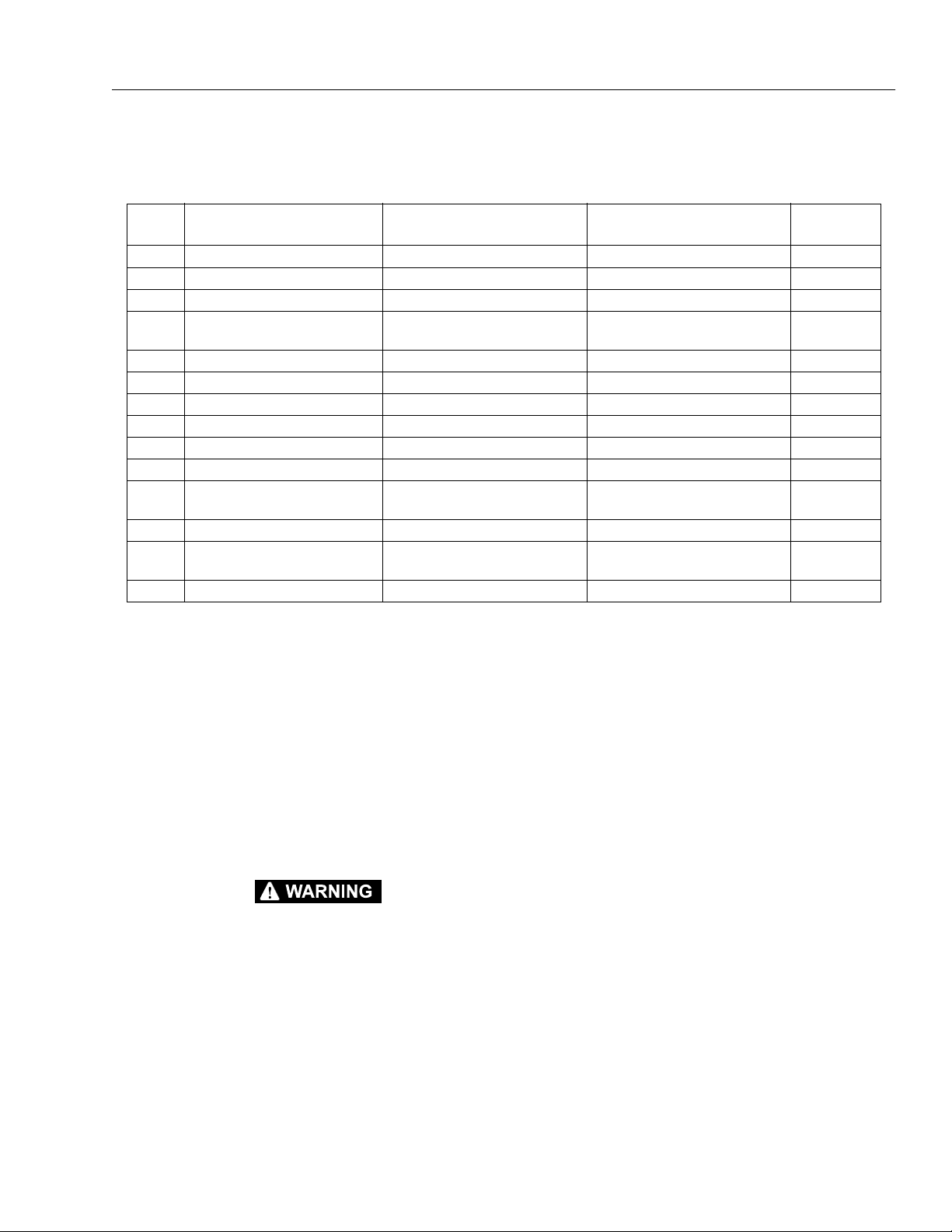
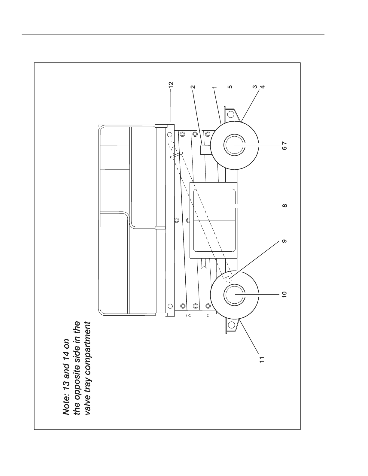
Table 1-2. Lubrication Chart
SECTION 1 - SPECIFICATIONS
INDEX
NO
1 Oscillating Axle Pivot Point (Optional) 1 Grease Fitting MPG - Pressure Gun 100
2 Lockout Cylinders ( Optional) 2 Grease Fitting s (1 each cylinder) MPG - Pressure Gun 100
3 Front Steering Spindles (2-W/D) 2 Grease Fittings MPG - Pressure Gun 100
4 Front Steering Spindles (4-W/D)
5 Tow Bar Hitch (Optional) 1 Grease Fitting MPG - Pressu re Gun 100
6 Wheel Bearings (2-W/D) N/A MPG - Repack 2000
7 *Whee l Drive Hub (4-W/D) (Optional) Fill Plug EPGL (SAE 90) 500
8 Engine Crankcase Fill Cap/Drain Plu g Check Engine Oi l Level 10/100
9 Lift Cylinder 2 Grease Fittings MPG - Pressure Gun 100
10 *Wheel Drive Hub Fill Plug EPGL (SAE 90) 500
11 Rear Steering Spind les (4-W/S)
12 Rail Slides N/A MPG - Brush 100
13 Hydraulic Oil Reser voir Fill Cap/Drain Plu g HO - Check HO Level (See note 4)/
14 ** Hydraulic Filter Element N/A Initial Change - 40 Ho urs 250
COMPONENT NUMBER/TYPE LUBE POINTS LUBE METHOD
2 Grease Fittings MPG - Pressure Gun 100
(Optional)
2 Grease Fittings MPG - Pressure Gun 100
(Optional)
HO - Change HO
INTERVAL
HOURS
10/500
*Torque Hubs should be 1/2 full of lubricant
** JLG Industries recommends replacing the hydraulic
filter after the first 40 hours of operation and every 250
hours thereafter.
KEY TO LUBRICANTS:
MPG - Multi-purpose Grease
EPGL - Extreme Pressure Gear Lube
HO - Hydraulic Oil (Mobil 424)
TO AVOID PERSONAL INJURY, USE SAFETY PROP FOR ALL
MAINTENANCE REQUIRING PLATFORM TO BE ELEVATED.
NOTE: When temperatures remain consistently below -7°
C ( 20° F ), JLG Industries recommends the use of
Mobil DTE11.
NOTE: 1. Be sure to lubricate like items on each side
2. Recommended lubricating intervals are based
on machine operations under normal conditions.
For machines used in multi-shift operations and/or
exposed to hostile environments or conditions,
lubrication frequencies must be increased accordingly.
3. Operate hydraulic functions through one complete cycle before checking hydraulic oil level in
tank. Oil should be visible in ADD sight window on
hydraulic tank. If oil is not visible, add oil until oil is
visible in both ADD and FULL sight windows on
tank. Do not overfill tank.
4. Any time the pump coupling is removed, coat
splines of coupling with Texaco Code 1912 grease
prior to assembly.
3120826 – JLG Sizzor – 1-5
SECTION 1 - SPECIFICATIONS
NOTE: Aside from JLG recommendations, it is not adv is abl e
to mix oils of different brands or types, as they may
not contain the same required additives or be of
comparable viscosities. If use of hydraulic oil other
than Mobilfluid 424 is desired, contact JLG Industries for proper recommendations.
Lubrication Specifications
Table 1-3. Lubrication Specifications
KEY SPECIFICATIONS
MPG Multipurpose Gre ase having a minimum dripping
point of 350 degress F. Excellent water resistanc e
and adhesive qualiti es, and being of extreme pres-
sure type. (Timken OK 40 pounds minimum.)
EPGL Extreme Pressure Gear Lube (oil ) meeting API ser-
vice classifica tion GL-5 or MIL-Spec MIL-L-2105.
EO Engine (crankcase) Oil. Gas - API SF /SG class, MIL-
L-2104. Diesel - API CC/CD class, MIL-L-2104B/
MIL-L-2104C.
HO Hydraulic Oil. A PI service classification GL- 3, e.g.
Mobil 424.
1.5 PRESSURE SETTINGS
2-W/S
2 Stack Racine Valve
Main Relief - 172 bar (2500 psi)
Steer Relief - 103 bar (1500 psi)
Lift Overload Relief Pressure
25RTS - 90 bar (1300 psi)
33RTS - 107 bar (1550 psi)
40RTS - 138 bar (2000 psi)
4-W/S
3 Stack Racine Valve (If Equipped)
Main Relief - 172 bar (2500 psi)
Steer Relief - 103 bar (1500 psi)
Lift Overload Relief Pressure
25RTS - 90 bar (1300 psi)
33RTS - 107 bar (1550 psi)
40RTS - 138 bar (2000 psi)
Leveling Jacks Valve (If Equipped) - 90 bar (1300 psi)
1-6 – JLG Sizzor – 3120826
SECTION 1 - SPECIFICATIONS
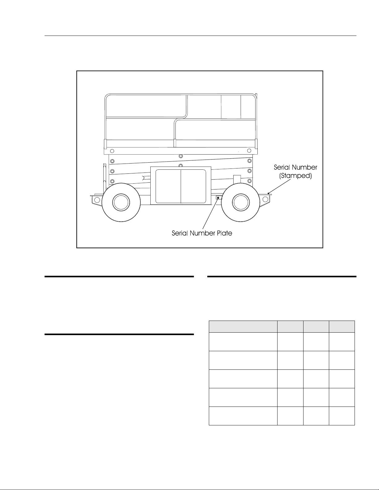
Figure 1-3. Serial Number Location
1.6 SERIAL NUMBER LOCATIONS
For machine identification, a serial number plate is affixed
to the machine. The plate is located on the right front side
of the frame rail. In addition, should the serial number
plate be damaged or missing, the machine serial number
is stamped on the top of frame between the front wheels.
1.7 LIMIT SWITCHES
The machine is equipped with the following limit switches:
High Drive Speed Cut-Out - High drive speed is cut out
when platform is raised above stowed (fully lowered) position.
Tilt Alarm - 3° - A horn is sounded and a warning light is
illuminated when the machine is operated on a slope that
exceeds 3° with the platform raised. If the machine is operated on a 3° slope with the platform completely lowered,
only the warning light is illuminated.
1.8 CYLINDER SPECIFICATIONS
NOTE: All dimensions are given in inches (in), with the met-
ric equivalent, centimeters (cm), in parentheses.
Table 1-4. Cylinder Specifications
Description Bore Stroke Rod Dia
Lift Cylinder
(25RTS/33RTS)
Lift Cylinder
(40RTS)
Lockout Cylind er
(Oscillating Axle)
Leveling Jack
Cylinder
Steer Cylinder 2.5
5.0
(12.7)
5.0
(12.7)
3.0
(7.6)
2.0
(5.1)
(6.4)
66.6
(169.2)
65.6
(166.4)
3.75
(9.5)
14.0
(35.6)
7.1
(18.1)
3.0
(7.6)
3.5
(8.9)
1.25
(3.2)
1.25
(3.2)
1.25
(3.2)
3120826 – JLG Sizzor – 1-7
SECTION 1 - SPECIFICATIONS
1.9 MAJOR COMPONENT WEIGHTS 1.10 CRITICAL STABILITY WEIGHTS
Table 1-5. Major Component Weights
Component Lb Kg
Fixed Platform 660 300
Platform Extension 300 136
Arm Assembly- 25 RTS (Incl udes
Lift Cylinder)
2403 1090
DO NOT REPLACE ITEMS CRITICAL TO STABILITY WITH ITEMS
OF DIFFERENT WEIGHT OR SPECIFICATION (FOR EXAMPLE:
FILLED TIRES, ENGINE) DO NOT MODIFY UNIT IN ANY WAY TO
AFFECT STABILITY.
Table 1-6. Critcal Stability Weights
Component Lb Kg
Arm Assembly- 33 RTS (Incl udes
Lift Cylinder)
Arm Assembly- 40 RTS (Incl udes
Lift Cylinder)
Chassis with Pneumatic Tires 3398 1541
Chassis with Foam Fil led Tires 4102 1860
3130 1418
3860 1750
Tires (Balasted Only) 295 134
Engine (Ford) 525 238
Engine (Deutz) 342 155
1-8 – JLG Sizzor – 3120826
SECTION 2. PROCEDURES
SECTION 2 - PROCEDURES
2.1 GENERAL
This section provides information necessary to perform
maintenance on the sizzor lift. Descriptions, techniques
and specific procedures are designed to provide the safest and most efficient maintenance for use by personnel
responsible for ensuring the correct installation and operation of machine components and systems.
WHEN AN ABNORMAL CONDITION IS NOTED AND PROCEDURES
CONTAINED HEREIN DO NOT SPECIFICALLY RELATE TO THE
NOTED IRREGULARITY, WORK SHOULD BE STOPPED AND
TECHNICALLY QUALIFIED GUIDANCE OBTAINED BEFORE WORK
IS RESUMED.
The maintenance procedures included consist of servicing and component removal and installation, disassembly
and assembly, inspection, lubrication and cleaning. Information on any special tools or test equipment is also provided where applicable.
2.2 SERVICING AND MAINTENANCE GUIDELINES
General
The following information is provided to assist you in the
use and application of servicing and maintenance procedures contained in this chapter.
Safety and Workmanship
Your safety, and that of others, is the first consideration
when engaging in the maintenance of equipment. Always
be conscious of weight. Never attempt to move heavy
parts without the aid of a mechanical device. Do not allow
heavy objects to rest in an unstable position. When raising
a portion of the equipment, ensure that adequate support
is provided.
Cleanliness
2. At any time when air, fuel, or oil lines are disconnected, clear adjacent areas as well as the openings
and fittings themselves. As soon as a line or component is disconnected, cap or cover all openings to
prevent entry of foreign matter.
3. Clean and inspect all parts during servicing or maintenance, and assure that all passages and openings
are unobstructed. Cover all parts to keep them
clean. Be sure all parts are clean before they are
installed. New parts should remain in their containers until they are ready to be used.
Components Removal and Installation
1. Use adjustable lifting devices, whenever possible, if
mechanical assistance is required. All slings (chains,
cables, etc.) should be parallel to each other and as
near perpendicular as possible to top of part being
lifted.
2. Should it be necessary to remove a component on
an angle, keep in mind that the capacity of an eyebolt or similar bracket lessens, as the angle between
the supporting structure and the component
becomes less than 90°.
3. If a part resists removal, check to see whether all
nuts, bolts, cables, brackets, wiring, etc., have been
removed and that no adjacent parts are interfering.
Component Disassembly and Reassembly
When disassembling or reassembling a component, complete the procedural steps in sequence. Do not partially
disassemble or assemble one part, then start on another.
Always recheck your work to assure that nothing has been
overlooked. Do not make any adjustments, other than
those recommended, without obtaining proper approval.
Pressure-Fit Parts
When assembling pressure-fit parts, use an “anti-seize” or
molybdenum disulfide base compound to lubricate the
mating surface.
1. The most important single item in preserving the
long service life of a machine is to keep dirt and foreign materials out of the vital components. Precautions have been taken to safeguard against this.
Shields, covers, seals, and filters are provided to
keep air, fuel, and oil supplies clean; however, these
items must be maintained on a scheduled basis in
order to function properly.
Bearings
1. When a bearing is removed, cover it to keep out dirt
and abrasives. Clean bearings in nonflammable
cleaning solvent and allow to drip dry. Compressed
air can be used but do not spin the bearing.
2. Discard bearings if the races and balls (or rollers)
are pitted, scored, or burned.
3120826 – JLG Sizzor – 2-1

SECTION 2 - PROCEDURES
3. If bearing is found to be serviceable, apply a light
coat of oil and wrap it in clean (waxed) paper. Do not
unwrap reusable or new bearings until they are
ready to install.
4. Lubricate new or used serviceable bearings before
installation. When pressing a bearing into a retainer
or bore, apply pressure to the outer race. If the bearing is to be installed on a shaft, apply pressure to the
inner race.
Gaskets
Check that holes in gaskets align with openings in the
mating parts. If it becomes necessary to hand-fabricate a
gasket, use gasket material or stock of equivalent material
and thickness. Be sure to cut holes in the right location, as
blank gaskets can cause serious system damage.
Bolt Usage and Torque Application
1. Use bolts of proper length. A bolt which is too long
will bottom before the head is tight against its related
part. If a bolt is too short, there will not be enough
thread area to engage and hold the part properly.
When replacing bolts, use only those having the
same specifications of the original, or one which is
equivalent.
2. Unless specific torque requirements are given within
the text, standard torque values should be used on
heat-treated bolts, studs, and steel nuts, in accordance with recommended shop practices.
Lubrication
Service applicable components with the amount, type,
and grade of lubricant recommended in this manual, at
the specified intervals. When recommended lubricants are
not available, consult your local supplier for an equivalent
that meets or exceeds the specifications listed.
Batteries
Clean batteries, using a non-metallic brush and a solution
of baking soda and water. Rinse with clean water. After
cleaning, thoroughly dry batteries and coat terminals with
an anti-corrosion compound.
Lubrication and Servicing
Components and assemblies requiring lubrication and
servicing are shown in Section 1.
2.3 LUBRICATION INFORMATION
Hydraulic System
1. The primary enemy of a hydraulic system is contamination. Contaminants enter the system by various
means, e.g., using inadequate hydraulic oil, allowing
moisture, grease, filings, sealing components, sand,
etc., to enter when performing maintenance, or by
permitting the pump to cavitate due to insufficient
system warm-up or leaks in the pump supply (suction) lines.
Hydraulic Lines and Electrical Wiring
Clearly mark or tag hydraulic lines and electrical wiring, as
well as their receptacles, when disconnecting or removing
them from the unit. This will assure that they are correctly
reinstalled.
Hydraulic System
1. Keep the system clean. If evidence of metal or rubber particles is found in the hydraulic system, drain
and flush the entire system.
2. Disassemble and reassemble parts on clean work
surface. Clean all metal parts with non-flammable
cleaning solvent. Lubricate components, as
required, to aid assembly.
2. The design and manufacturing tolerances of the
component working parts are very close, therefore,
even the smallest amount of dirt or foreign matter
entering a system can cause wear or damage to the
components and generally results in faulty operation. Every precaution must be taken to keep
hydraulic oil clean, including reserve oil in storage.
Hydraulic system filters should be checked,
cleaned, and/or replaced as necessary, at the specified intervals required in Section 1. Always examine
filters for evidence of metal particles.
3. Cloudy oils indicate a high moisture content which
permits organic growth, resulting in oxidation or corrosion. If this condition occurs, the system must be
drained, flushed, and refilled with clean oil.
4. It is not advisable to mix oils of different brands or
types, as they may not contain the same required
additives or be of comparable viscosities. Good
grade mineral oils, with viscosities suited to the
ambient temperatures in which the machine is operating, are recommended for use.
2-2 – JLG Sizzor – 3120826

SECTION 2 - PROCEDURES
NOTE: Metal particles may appear in the oil or filters of new
machines due to the wear-in of meshing components.
Hydraulic Oil
1. Refer to Section 1 for recommendations for viscosity
ranges.
2. JLG recommends Mobilfluid 424 oil, which has an
SAE viscosity of 10W-30 and a viscosity index of
152.
NOTE: Start-up of hydraulic system with oil temperatures
below -26° C (-15° F). is not recommended. If it is
necessary to start the system in a sub-zero environment, it will be necessary to heat the oil with a low
density , 100V A C heater to a m inimum t emperature of
-26° C (-15° F).
3. The only exception to the above is to drain and fill
the system with Mobil DTE 11 oil or its equivalent.
This will allow start up at temperatures down to -29°
C (-20 ° F). However, use of this oil will give poor performance at temperatures above 49° C (120° F). Sys-
tems using DTE 11 oil should not be operated at
temperatures above 94° C (200° F). under any condition.
Changing Hydraulic Oil
1. Use of any of the recommended crankcase or
hydraulic oils eliminates the need for changing the
oil on a regular basis. However, filter elements must
be changed after the first 50 hours of operation and
every 300 hours thereafter. If it is necessary to
change the oil, use only those oils meeting or
exceeding the specifications appearing in this manual. If unable to obtain the same type of oil supplied
with the machine, consult local supplier for assistance in selecting the proper equivalent. Avoid mixing petroleum and synthetic base oils. JLG
Industries recommends changing the hydraulic oil
annually.
2. Use every precaution to keep the hydraulic oil clean.
If the oil must be poured from the original container
into another, be sure to clean all possible contaminants from the service container. Always clean the
mesh element of the filter and replace the cartridge
any time the system oil is changed.
3. While the unit is shut down, a good preventive maintenance measure is to make a thorough inspection
of all hydraulic components, lines, fittings, etc., as
well as a functional check of each system, before
placing the machine back in service.
Lubrication Specifications
Specified lubricants, as recommended by the component
manufacturers, are always the best choice, however,
multi-purpose greases usually have the qualities which
meet a variety of single purpose grease requirements.
Should any question arise regarding the use of greases in
maintenance stock, consult your local supplier for evaluation. Refer to Section 1 for an explanation of the lubricant
key designations appearing in the Lubrication Chart.
2.4 CYLINDERS - THEORY OF OPERATION
Cylinders are of the double acting type. The Lift and Steer
systems incorporate double acting cylinders. A double
acting cylinder is one that requires oil flow to operate the
cylinder rod in both directions. Directing oil (by actuating
the corresponding control valve to the piston side of the
cylinder) forces the piston to travel toward the rod end of
the barrel, extending the cylinder rod (piston attached to
rod). When the oil flow is stopped, movement of the rod
will stop. By directing oil to the rod side of the cylinder, the
piston will be forced in the opposite direction and the cylinder rod will retract.
NOTE: The lift cylinder is a single acting cylinder which
takes hydraulic pressure to extend and gravity to
retract.
A holding valve is used in the Lift circuit to prevent retraction of the cylinder rod should a hydraulic line rupture or a
leak develop between the cylinder and its related control
valve.
2.5 VALVES - THEORY OF OPERATION
Solenoid Control Valves (Bang-Bang)
Control valves used are four-way three-position solenoid
valves of the sliding spool design. When a circuit is activated and the control valve solenoid energizes, the spool
is shifted and the corresponding work port opens to permit oil flow to the component in the selected circuit, with
the opposite work port opening to reservoir. Once the circuit is deactivated (control returned to neutral), the valve
spool returns to neutral (center) and oil flow is then
directed through the valve body and returns to reservoir.
A typical control valve consists of the valve body, sliding
spool, and two solenoid assemblies. The spool is
machine fitted in the bore of the valve body. Lands on the
spool divide the bore into various chambers, which, when
the spool is shifted, align with corresponding ports in the
valve body open to common flow. At the same time other
ports would be blocked to flow. The spool is springloaded to center position, therefore when the control is
released, the spool automatically returns to neutral, prohibiting any flow through the circuit.
3120826 – JLG Sizzor – 2-3

SECTION 2 - PROCEDURES
Relief Valves
Main relief valves are installed at various points within the
hydraulic system to protect associated systems and components against excessive pressure. Excessive pressure
can be developed when a cylinder reaches its limit of
travel and the flow of pressurized fluid continues from the
system control. The relief valve provides an alternate path
for the continuing flow from the pump, thus preventing
rupture of the cylinder, hydraulic line or fitting. Complete
failure of the system pump is also avoided by relieving circuit pressure. The relief valve is installed in the circuit
between the pump outlet (pressure line) and the cylinder
of the circuit, generally as an integral part of the system
valve bank. Relief pressures are set slightly higher than
the load requirement, with the valve diverting excess
pump delivery back to the reservoir when operating pressure of the component is reached.
Crossover Relief Valves
Crossover relief valves are used in circuits where the actuator requires an operating pressure lower than that supplied to the system. When the circuit is activated and the
required pressure at the actuator is developed, the crossover relief diverts excess pump flow to the reservoir. Individual, integral relief’s are provided for each side of the
circuit.
2.7 SLIDING WEAR PADS
The original thickness of the sliding pads is 50.8 mm (2.0
in.). Replace sliding pads when worn to 47.5 mm (1.87in.).
2.8 PUMP AND COUPLING LUBRICATION
To insure proper operation and a long service life for the
Hayes pump coupling, it is necessary to lubricate the
splines of the coupling any time the coupling is disassembled or replaced. Lubricate the splines with Texaco Code
1912 Pump Coupling Grease ONLY. No other lubricant is
recommended.
2.6 COMPONENT FUNCTIONAL DESCRIPTION
Piston Hydraulic Pump
The Sundstrand piston hydraulic pump is attached to and
driven by the engine. The pump is a 45.9 cm[3] (2.8 in.[3])
displacement piston pump that powers the drive motors.
Gear Hydraulic Pump
The John Barnes gear pump is “piggy-backed” to the pis-
ton pump, and operates all machine functions except
drive. The gear pump has a displacement of 10.5 cm[3]
(0.6 in. [3]).
Manual Descent Valve
The manual descent valve is located on top of the holding
valve on the lift cylinder. The holding valve is a normally
closed solenoid valve, and holds the platform in place
when raised. When activated, the valve opens to permit lift
down. The holding valve is connected to the manual
descent valve, which is connected to a cable which, when
pulled, manually opens the lift down port of the valve and
allows the platform to be lowered in the event hydraulic
power is lost.
Figure 2-1. Pump and Coupling Lubrication
2.9 CYLINDER CHECKING PROCEDURES
NOTE: Cylinder checks must be performed any time a cylin-
der component is repl ac ed or wh en im pro per system
operation is suspected.
Cylinder w/o Counterbalance Valves - Steer Cylinder, Axle Lockout Cylinder (If Equipped)
OPERATE FUNCTIONS FROM GROUND CONTROL STATION
ONLY.
1. Using all applicable safety precautions, activate
hydraulic system and fully extend cylinder to be
checked. Shut down hydraulic system.
2-4 – JLG Sizzor – 3120826
SECTION 2 - PROCEDURES
2. Carefully disconnect hydraulic hose from retract port
of cylinder. There will be initial weeping of hydraulic
fluid which can be caught in a suitable container.
After the initial discharge, there should be no further
leakage from the retract port.
3. Activate hydraulic system and activate cylinder
extend function. Check retract port for leakage.
4. If cylinder leakage is 6-8 drops per minute or more,
piston seals are defective and must be replaced. If
cylinder retract port leakage is less than 6-8 drops
per minute, carefully reconnect hose to retract port
and retract cylinder.
5. With cylinder fully retracted, shut down hydraulic
system and carefully disconnect hydraulic hose
from cylinder extend port.
6. Activate motor and activate cylinder retract function.
Check extend port for leakage.
7. If cylinder leakage is 6-8 drops per minute or more,
piston seals are defective and must be replaced. If
extend port leakage is less than 6-8 drops per
minute, carefully reconnect hose to extend port,
then activate cylinder through one complete cycle
and check for leaks.
port is leaking, the counterbalance valve is defective
and must be replaced.
5. If no repairs are necessary or when repairs have
been made, carefully reconnect hydraulic hoses to
the appropriate ports.
6. Remove lifting device from platform, activate hydraulic system and run cylinder through one complete
cycle to check for leaks.
2.10 CYLINDER REMOVAL AND INSTALLATION
Lift Cylinder Removal
1. Place the machine on a flat and level surface. Start
the engine/motor and raise the platform. Shut down
the engine/motor and attach a suitable support
device to the platform.
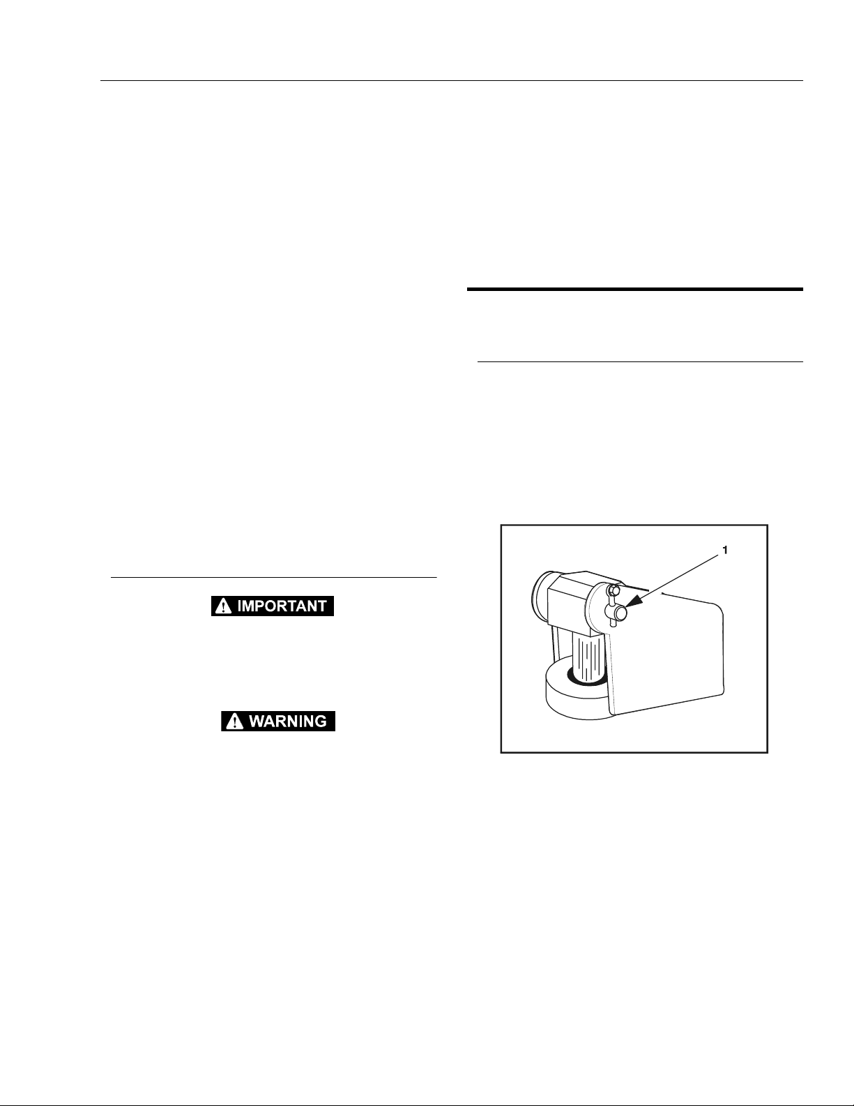
2. Remove the bolts, lock washers, and flat washers
securing the cylinder rod attach pin #1 to the upper
inner arm assembly. Using a suitable brass drift,
drive out the rod end attach pin from the arm assembly.
Cylinders w/Single Counterbalance Valves Lift Cylinder
OPERATE ALL FUNCTIONS FROM GROUND CONTROL STATION
ONLY.
1. Using all applicable safety precautions, activate
hydraulic system.
WHEN WORKING ON THE LIFT CYLINDER, RAISE THE PLATFORM COMPLETELY AND SUPPORT THE PLATFORM USING A
SUITABLE OVERHEAD LIFTING DEVICE.
2. Raise platform completely and place a suitable overhead lifting device or prop approximately 2.5 cm (1
in.) below the platform.
3. Shut down hydraulic system and allow machine to
sit for 10-15 minutes. Carefully remove hydraulic
hoses from cylinder port block.
4. There will be initial weeping of hydraulic fluid, which
can be caught in a suitable container. After the initial
discharge, there should not be any further leakage
from the ports. If leakage continues at a rate of 6-8
drops per minute or more, cylinder repairs must be
made. If the retract port is leaking, the piston seals
are defective and must be replaced. If the extend
Figure 2-2. Top Lift Cylinder Pin Location
3. Retract the lift cylinder rod completely.
4. Tag and disconnect, then cap the lift cylinder
hydraulic lines and ports.
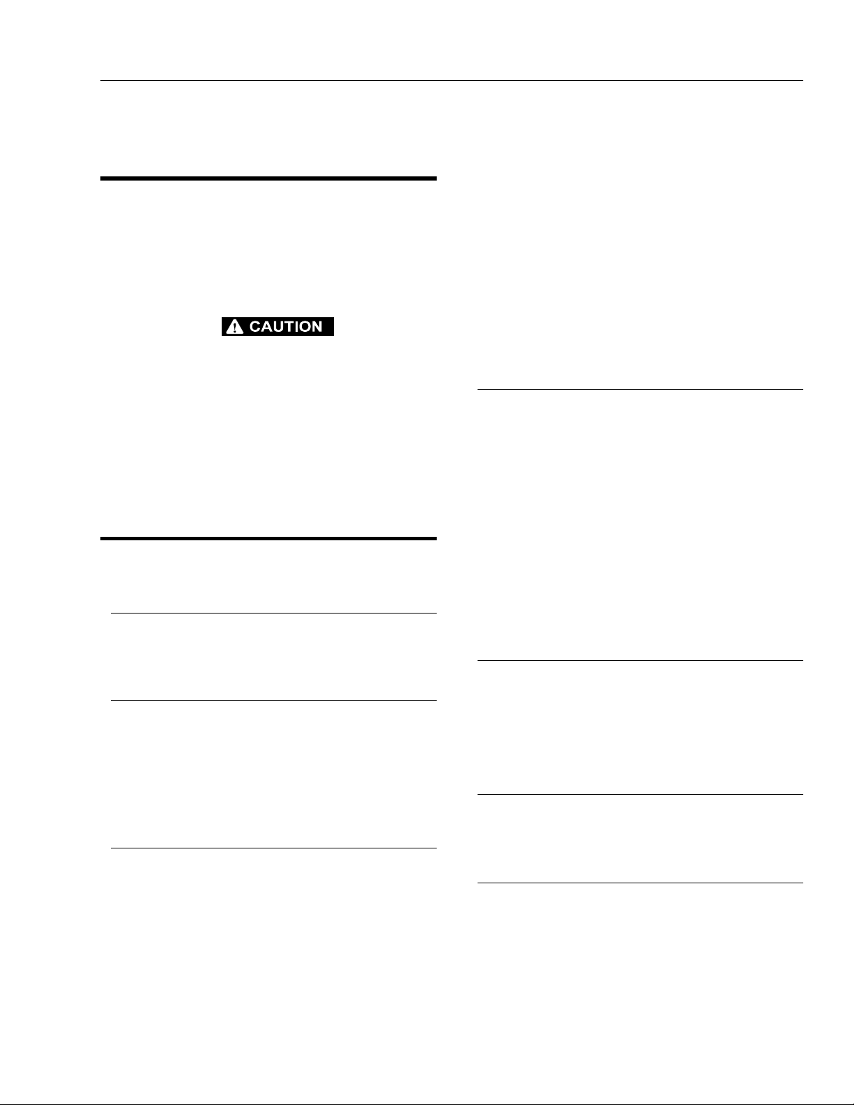
5. Remove the bolts, lock washers, and flat washers
securing the barrel end attach pin to the lower arm
assembly. Using a suitable brass drift, drive out the
barrel end attach pin #2 from the arm assembly.
3120826 – JLG Sizzor – 2-5
SECTION 2 - PROCEDURES
Figure 2-3. Bottom Lift Cylinder Pin Location
6. Carefully remove the cylinder from the Sizzor lift and
place in a suitable work area.
2.11 CYLINDER REPAIR
NOTE: The following are general procedures that apply to
all of the cylinders on this machine. Procedures that
apply to a specific cylinder will be so noted.
Disassembly
DISASSEMBLY OF THE CYLINDER SHOULD BE PERFORMED ON
A CLEAN WORK SURFACE IN A DIRT FREE WORK AREA.
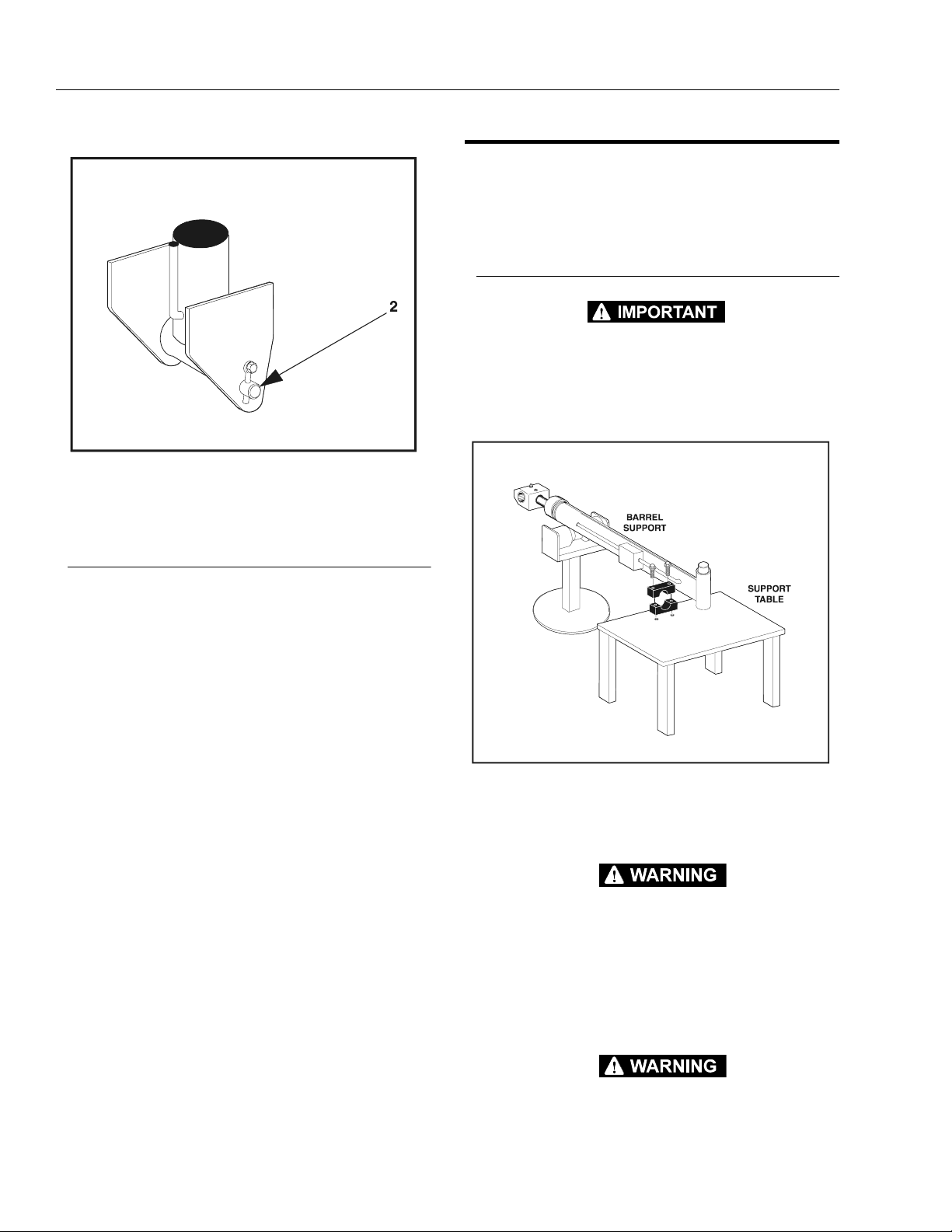
1. Place the cylinder barrel into a suitable holding fixture.
Lift Cylinder Installation
1. Install lift cylinder in place using suitable slings or
supports, aligning barrel end attach pin #2 mounting holes on lower arm assembly.
2. Using a suitable drift, drive the barrel end attach pin
#2 through the mounting holes in the lift cylinder
and the lower arm assembly. Secure in place with
the bolts, flat washers, and lock washers.
3. Remove cylinder port plugs and hydraulic line caps
and correctly attach lines to cylinder ports.
4. Extend the cylinder rod until the attach pin #1 hole
aligns with those in the upper arm assembly. Using a
suitable drift, drive the cylinder rod attach pin #1
through the aligned holes. Secure the pin in place
with the bolts, lock washers, and flat washers.
5. Remove support from platform and position the
safety props to the stowed position.
6. Lower platform to stowed position and shut down
motor/engine. Check hydraulic fluid level and adjust
accordingly.
Figure 2-4. Cylinder Barrel Support
2. Connect a suitable auxiliary hydraulic power source
to the cylinder port block fitting.
DO NOT FULLY EXTEND CYLINDER TO THE END OF STROKE.
RETRACT CYLINDER SLIGHTLY TO AVOID TRAPPING PRESSURE.
3. Operate the hydraulic power source and extend the
cylinder. Shut down and disconnect the power
source. Adequately support the cylinder rod, if applicable.
CYLINDERS WITH DOUBLE HOLDING VALVES. BEFORE REMOVING HOLDING VALVES CRACK BLEEDER TO RELEASE PRESSURE.
2-6 – JLG Sizzor – 3120826

SECTION 2 - PROCEDURES
Figure 2-5. Arms and Platform Positioning and Support, Cylinder Repair
3120826 – JLG Sizzor – 2-7
SECTION 2 - PROCEDURES
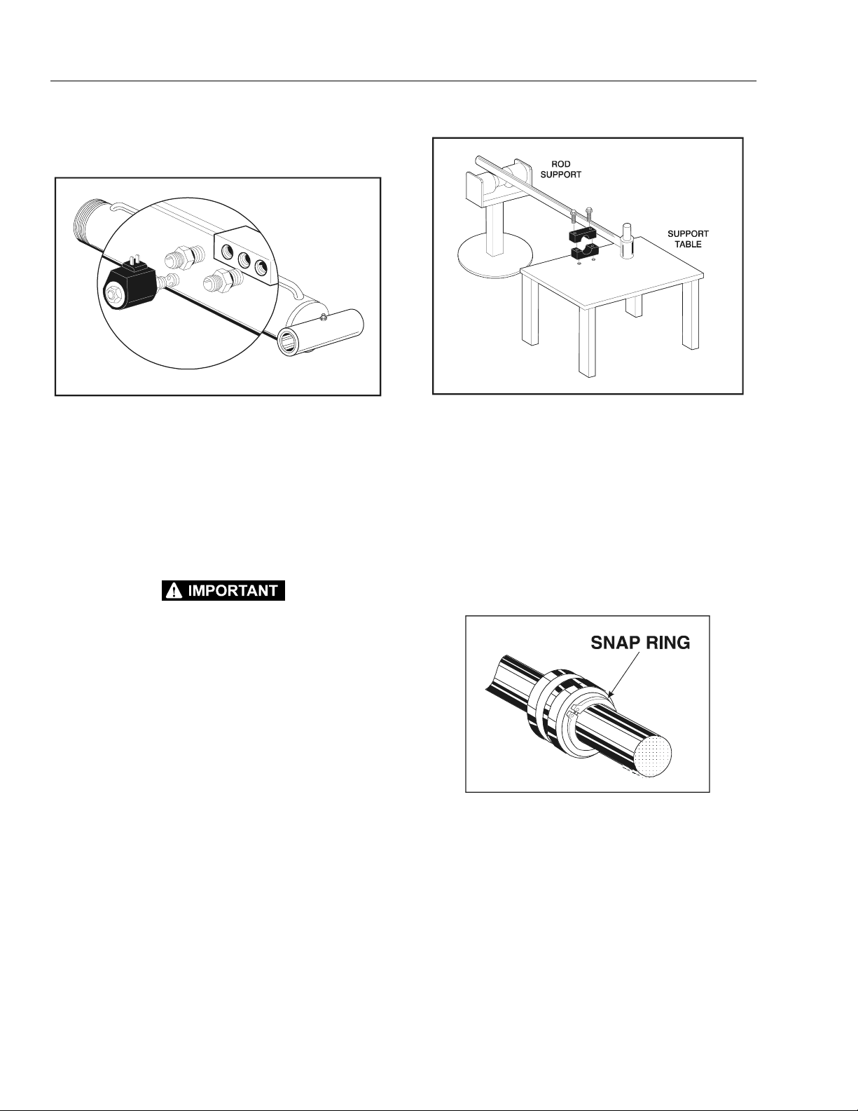
Figure 2-6. Holding Valve and Fitting Removal
4. If applicable, remove the cartridge-type holding
valve and fittings from the cylinder port block. Discard o-rings.
Figure 2-7. Cylinder Rod Support
5. Tap around outside of cylinder head retainer with a
suitable hammer to shatter loctite.
6. Using a suitable chain wrench, loosen the cylinder
head retainer, if applicable, and/or cylinder head
gland, and remove from cylinder barrel.
7. Attach a suitable pulling device to the cylinder rod
port block end or cylinder rod end, as applicable.
EXTREME CARE SHOULD BE TAKEN WHEN REMOVING THE CYLINDER ROD, HEAD, AND PISTON. AVOID PULLING THE ROD OFFCENTER, WHICH COULD CAUSE DAMAGE TO THE PISTON AND
CYLINDER BARREL SURFACES.
8. With the barrel clamped securely, apply pressure to
the rod pulling device and carefully withdraw the
complete rod assembly from the cylinder barrel.
9. Using suitable protection, clamp the cylinder rod in
a vise or similar holding fixture as close to the piston
as possible.
10. Remove the set screw(s), if applicable, and nut
which attach the piston to the rod, and remove the
piston. Discard set screws.
NOTE: Steer Cylinder has two retainers at each e nd of cyli n-
der.
11. This step only applies to the steer cylinder, remove
snap rings from rod which attach the piston to the
rod.
Figure 2-8. Steer Cylinder Snap Ring Removal
12. Remove and discard the piston o-rings, seal rings,
and wear rings.
13. Remove piston spacer, and head, from the rod. Discard the o-rings, back-up rings, rod seals, and wiper
seals.
14. Remove the cylinder head gland. Remove the rod
from the holding fixture.
2-8 – JLG Sizzor – 3120826

SECTION 2 - PROCEDURES
Cleaning and Inspection
1. Clean all parts thoroughly in an approved cleaning
solvent.
2. Inspect the cylinder rod for scoring, tapering, ovality,
or other damage. If necessary, dress rod with
Scotch Brite or equivalent. Replace rod if necessary.
3. Inspect threaded portion of rod for excessive damage. Dress threads as necessary.
4. Inspect inner surface of cylinder barrel tube for scoring or other damage. Check inside diameter for
tapering or ovality. Replace if necessary.
5. Inspect threaded portion of barrel for damage. Dress
threads as necessary.
6. Inspect piston surface for damage and scoring and
for distortion. Dress piston surface or replace piston
as necessary.
7. Inspect seal and o-ring grooves in piston for burrs
and sharp edges. Dress applicable surfaces as necessary.
8. Inspect cylinder head inside diameter for scoring or
other damage and for ovality and tapering. Replace
as necessary.
9. Inspect seal and o-ring grooves in head for burrs
and sharp edges. Dress applicable surfaces as necessary.
Assembly
NOTE: Prior to cylinder assembly, ensure that the proper
cylinder seal kit is used.
Apply a light film of hydraulic oil to all components
prior to assembly.
1. Place a new wiper seal and rod seal into the applicable cylinder head gland grooves.
Figure 2-9. Rod Seal Installation
Use a soft mallet to tap a new wiper seal into the applicable cylinder head gland groove.
10. If applicable, inspect cylinder head retainer or end
cap for surface or thread damage. Repair or replace
as necessary.
11. Inspect cylinder head outside diameter for scoring
or other damage and ovality and tapering. Replace
as necessary.
12. If applicable, inspect thread ring for scoring or other
damage. Dress threads or applicable surfaces as
necessary.
13. If applicable, inspect rod and barrel bushings for
signs of correct lubrication and excessive wear.
Replace as necessary.
14. Inspect travel limiting collar or spacer for burrs and
sharp edges. If necessary, dress inside diameter
surface with Scotch Brite or equivalent.
15. If applicable, inspect port block fittings and holding
valve. Replace as necessary.
16. Inspect the oil ports for blockage or the presence of
dirt or other foreign material. Repair as necessary.
17. If applicable, inspect piston rings for cracks or other
damage. Replace as necessary.
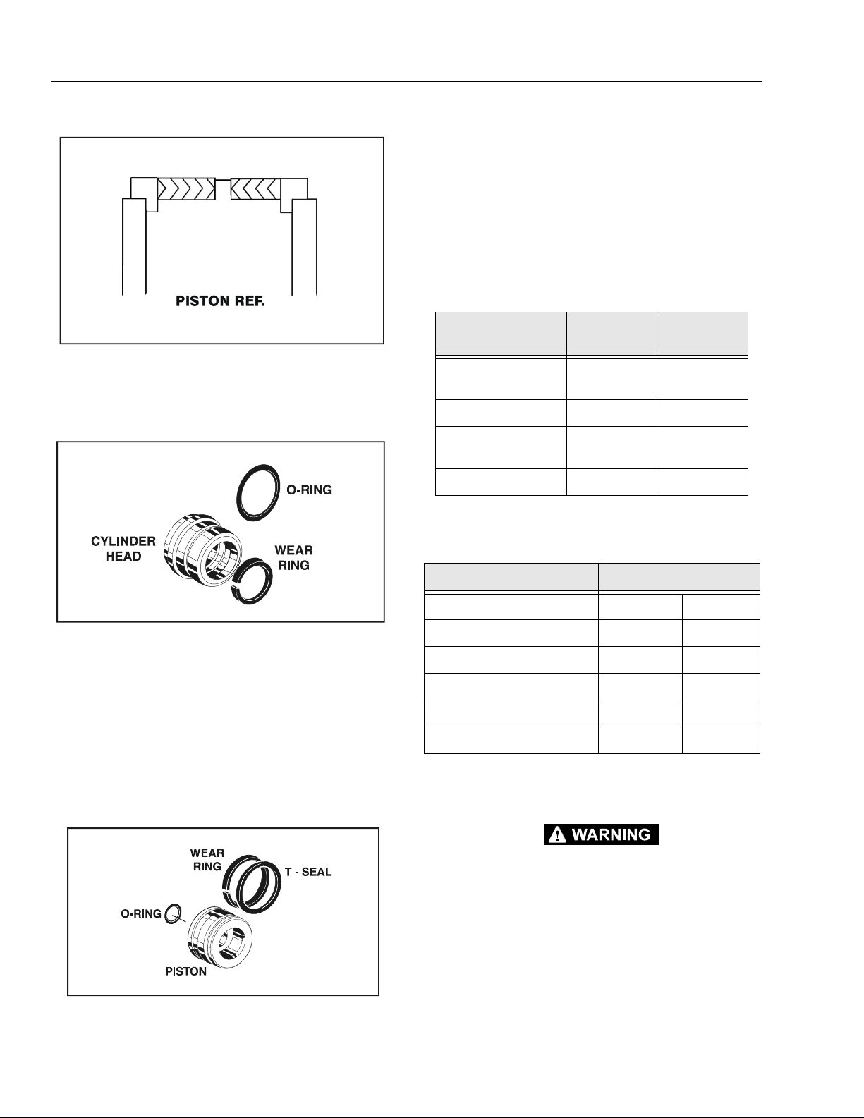
Figure 2-10. WIper Seal Installation
WHEN INSTALLING NEW “POLY-PAK” TYPE PISTON SEALS
(AXLE LOCKOUT CYLINDER), ENSURE SEALS ARE INSTALLED
PROPERLY. REFER TO FIGURE 2-11 FOR CORRECT SEAL ORIENTATION. IMPROPER SEAL INSTALLATION COULD RESULT IN
CYLINDER LEAKAGE AND IMPROPER CYLINDER OPERATION.
3120826 – JLG Sizzor – 2-9
SECTION 2 - PROCEDURES
Figure 2-11. Poly-Pak Seal Installation
Figure 2-12. Wear Seal Installation
Figure 2-13. Piston O-Ring Installation
4. Carefully slide the piston spacer on the rod. If applicable, align the oil holes in the rod and the spacer.
Secure the spacer, if applicable.
5. Carefully place the piston on the cylinder rod, ensuring that the o-ring is not damaged or dislodged.
6. Using suitable protection, clamp the cylinder rod in
a vise or similar holding fixture as close to the piston
as possible.
Table 2-1. Cylinder Piston Nut Torque Specifications
1. Place a new wear ring into the inner head diameter
groove and a new o-ring on the outer diameter
groove.
2. Carefully install the head gland on the rod, ensuring
that the wiper and rod seals are not damaged or dislodged. Push the head along the rod to the rod end,
as applicable.
3. Place a new o-ring into the inner piston diameter
groove and a new o-ring and wear ring on the outer
diameter groove
.
Description
Nut Torque
Value
Lift Cylinder 400 ft lb
(542 Nm)
Setscrew
torque Value
100 in lb
(12 Nm)
Lockout Cylinde r N/A N/A
Level Cylinder 5 0 ft lb
(68 Nm)
100 in lb
(12 Nm)
Steer Cylinder N/A N/A
Table 2-2. Holding Valve Torque Specifications
Description Torque Value
Sun - 7/8 hex M20 x 1.5 thds 30 - 35 ft lb 41 - 48 Nm
Sun - 1-1/8 hex 1 - 1 4 UNS thds 45 - 50 ft lb 61 - 68 Nm
Sun - 1-1/4 hex M36 x 2 thds 150 - 153 ft lb 204 - 207 Nm
Racine - 1-1/8 hex 1-1/16 - 12 thds 50 - 55 ft lb 68 - 75 Nm
Racine - 1-3/8 hex 1-3/16 - 12 thds 75 - 80 ft lb 102 - 109 Nm
Racine - 1-7/8 hex 1-5/8 - 12 thds 100 - 110 ft lb 136 - 149 Nm
9. Push the piston onto the rod until it abuts the spacer
end and install the attaching nut.
WHEN REBUILDING THE CYLINDERS, APPLY LOCTITE #242 TO
PISTON NUT AND SETSCREW, THEN TORQUE PISTON NUT.
REFER TO TABLE 2-1, CYLINDER PISTON NUT TORQUE SPECIFICATIONS
NOTE: The Steer Cylinder uses snap rings to secure piston.
10. Prior to setscrew installation spot drill rod before
installing the setscrew(s) which secure the piston
attaching nut to the diameter groove.
2-10 – JLG Sizzor – 3120826
 Loading...